WO2019189281A1 - Ensemble ressort hélicoïdal - Google Patents
Ensemble ressort hélicoïdal Download PDFInfo
- Publication number
- WO2019189281A1 WO2019189281A1 PCT/JP2019/013047 JP2019013047W WO2019189281A1 WO 2019189281 A1 WO2019189281 A1 WO 2019189281A1 JP 2019013047 W JP2019013047 W JP 2019013047W WO 2019189281 A1 WO2019189281 A1 WO 2019189281A1
- Authority
- WO
- WIPO (PCT)
- Prior art keywords
- coil spring
- seat
- enlarged diameter
- spring assembly
- end winding
- Prior art date
- Legal status (The legal status is an assumption and is not a legal conclusion. Google has not performed a legal analysis and makes no representation as to the accuracy of the status listed.)
- Ceased
Links
Images


Classifications
-
- B—PERFORMING OPERATIONS; TRANSPORTING
- B60—VEHICLES IN GENERAL
- B60K—ARRANGEMENT OR MOUNTING OF PROPULSION UNITS OR OF TRANSMISSIONS IN VEHICLES; ARRANGEMENT OR MOUNTING OF PLURAL DIVERSE PRIME-MOVERS IN VEHICLES; AUXILIARY DRIVES FOR VEHICLES; INSTRUMENTATION OR DASHBOARDS FOR VEHICLES; ARRANGEMENTS IN CONNECTION WITH COOLING, AIR INTAKE, GAS EXHAUST OR FUEL SUPPLY OF PROPULSION UNITS IN VEHICLES
- B60K17/00—Arrangement or mounting of transmissions in vehicles
-
- F—MECHANICAL ENGINEERING; LIGHTING; HEATING; WEAPONS; BLASTING
- F16—ENGINEERING ELEMENTS AND UNITS; GENERAL MEASURES FOR PRODUCING AND MAINTAINING EFFECTIVE FUNCTIONING OF MACHINES OR INSTALLATIONS; THERMAL INSULATION IN GENERAL
- F16F—SPRINGS; SHOCK-ABSORBERS; MEANS FOR DAMPING VIBRATION
- F16F1/00—Springs
- F16F1/02—Springs made of steel or other material having low internal friction; Wound, torsion, leaf, cup, ring or the like springs, the material of the spring not being relevant
- F16F1/04—Wound springs
- F16F1/12—Attachments or mountings
- F16F1/125—Attachments or mountings where the end coils of the spring engage an axial insert
-
- F—MECHANICAL ENGINEERING; LIGHTING; HEATING; WEAPONS; BLASTING
- F16—ENGINEERING ELEMENTS AND UNITS; GENERAL MEASURES FOR PRODUCING AND MAINTAINING EFFECTIVE FUNCTIONING OF MACHINES OR INSTALLATIONS; THERMAL INSULATION IN GENERAL
- F16F—SPRINGS; SHOCK-ABSORBERS; MEANS FOR DAMPING VIBRATION
- F16F1/00—Springs
- F16F1/02—Springs made of steel or other material having low internal friction; Wound, torsion, leaf, cup, ring or the like springs, the material of the spring not being relevant
- F16F1/04—Wound springs
- F16F1/12—Attachments or mountings
- F16F1/128—Attachments or mountings with motion-limiting means, e.g. with a full-length guide element or ball joint connections; with protective outer cover
-
- F—MECHANICAL ENGINEERING; LIGHTING; HEATING; WEAPONS; BLASTING
- F16—ENGINEERING ELEMENTS AND UNITS; GENERAL MEASURES FOR PRODUCING AND MAINTAINING EFFECTIVE FUNCTIONING OF MACHINES OR INSTALLATIONS; THERMAL INSULATION IN GENERAL
- F16F—SPRINGS; SHOCK-ABSORBERS; MEANS FOR DAMPING VIBRATION
- F16F15/00—Suppression of vibrations in systems; Means or arrangements for avoiding or reducing out-of-balance forces, e.g. due to motion
- F16F15/10—Suppression of vibrations in rotating systems by making use of members moving with the system
- F16F15/12—Suppression of vibrations in rotating systems by making use of members moving with the system using elastic members or friction-damping members, e.g. between a rotating shaft and a gyratory mass mounted thereon
- F16F15/121—Suppression of vibrations in rotating systems by making use of members moving with the system using elastic members or friction-damping members, e.g. between a rotating shaft and a gyratory mass mounted thereon using springs as elastic members, e.g. metallic springs
- F16F15/123—Wound springs
- F16F15/1232—Wound springs characterised by the spring mounting
- F16F15/12326—End-caps for springs
- F16F15/12333—End-caps for springs having internal abutment means
-
- B—PERFORMING OPERATIONS; TRANSPORTING
- B60—VEHICLES IN GENERAL
- B60Y—INDEXING SCHEME RELATING TO ASPECTS CROSS-CUTTING VEHICLE TECHNOLOGY
- B60Y2400/00—Special features of vehicle units
- B60Y2400/48—Vibration dampers, e.g. dual mass flywheels
-
- F—MECHANICAL ENGINEERING; LIGHTING; HEATING; WEAPONS; BLASTING
- F16—ENGINEERING ELEMENTS AND UNITS; GENERAL MEASURES FOR PRODUCING AND MAINTAINING EFFECTIVE FUNCTIONING OF MACHINES OR INSTALLATIONS; THERMAL INSULATION IN GENERAL
- F16F—SPRINGS; SHOCK-ABSORBERS; MEANS FOR DAMPING VIBRATION
- F16F1/00—Springs
- F16F1/02—Springs made of steel or other material having low internal friction; Wound, torsion, leaf, cup, ring or the like springs, the material of the spring not being relevant
- F16F1/04—Wound springs
- F16F1/042—Wound springs characterised by the cross-section of the wire
-
- F—MECHANICAL ENGINEERING; LIGHTING; HEATING; WEAPONS; BLASTING
- F16—ENGINEERING ELEMENTS AND UNITS; GENERAL MEASURES FOR PRODUCING AND MAINTAINING EFFECTIVE FUNCTIONING OF MACHINES OR INSTALLATIONS; THERMAL INSULATION IN GENERAL
- F16F—SPRINGS; SHOCK-ABSORBERS; MEANS FOR DAMPING VIBRATION
- F16F2226/00—Manufacturing; Treatments
- F16F2226/04—Assembly or fixing methods; methods to form or fashion parts
- F16F2226/045—Press-fitting
-
- F—MECHANICAL ENGINEERING; LIGHTING; HEATING; WEAPONS; BLASTING
- F16—ENGINEERING ELEMENTS AND UNITS; GENERAL MEASURES FOR PRODUCING AND MAINTAINING EFFECTIVE FUNCTIONING OF MACHINES OR INSTALLATIONS; THERMAL INSULATION IN GENERAL
- F16F—SPRINGS; SHOCK-ABSORBERS; MEANS FOR DAMPING VIBRATION
- F16F2228/00—Functional characteristics, e.g. variability, frequency-dependence
- F16F2228/001—Specific functional characteristics in numerical form or in the form of equations
-
- F—MECHANICAL ENGINEERING; LIGHTING; HEATING; WEAPONS; BLASTING
- F16—ENGINEERING ELEMENTS AND UNITS; GENERAL MEASURES FOR PRODUCING AND MAINTAINING EFFECTIVE FUNCTIONING OF MACHINES OR INSTALLATIONS; THERMAL INSULATION IN GENERAL
- F16F—SPRINGS; SHOCK-ABSORBERS; MEANS FOR DAMPING VIBRATION
- F16F2230/00—Purpose; Design features
- F16F2230/0005—Attachment, e.g. to facilitate mounting onto confer adjustability
-
- F—MECHANICAL ENGINEERING; LIGHTING; HEATING; WEAPONS; BLASTING
- F16—ENGINEERING ELEMENTS AND UNITS; GENERAL MEASURES FOR PRODUCING AND MAINTAINING EFFECTIVE FUNCTIONING OF MACHINES OR INSTALLATIONS; THERMAL INSULATION IN GENERAL
- F16F—SPRINGS; SHOCK-ABSORBERS; MEANS FOR DAMPING VIBRATION
- F16F2238/00—Type of springs or dampers
- F16F2238/02—Springs
- F16F2238/026—Springs wound- or coil-like
Definitions
- the present invention relates to a coil spring assembly used for an automobile transmission damper or the like.
- a coil spring and a seat member attached to a coiled portion of the coil spring are provided.
- the seat member has a seat portion and an attachment shaft portion.
- the seat portion is formed in a circular shape and is in contact with the end face of the coil winding portion of the coil spring.
- the mounting shaft portion protrudes from the center portion of the seat portion, and a diameter-expanding portion is provided at the tip portion in the axial direction.
- the enlarged diameter portion is press-fitted into the inner periphery of the end winding portion of the coil spring, and the outer periphery of the attachment shaft portion is engaged with the end winding portion that has passed over the enlarged diameter portion.
- the sheet member is prevented from falling off (rotational direction omission and axial omission) due to rotation relative to the axial direction between the coil spring and the sheet member. Is possible.
- the coil spring may be destroyed when the diameter-enlarged portion of the sheet member is press-fitted if the sheet member is prevented from falling off due to the rotation of the coil spring and the sheet member relative to the axial direction. There is a point that the expanded diameter portion of the sheet member easily interferes with the coil spring after press-fitting.
- the present invention provides a coil spring assembly that can suppress the dropping of a sheet member while suppressing damage to the coil spring at the time of press-fitting a diameter-enlarged portion of the sheet member and interference with the coil spring after the press-fitting.
- the coil spring assembly includes a coil spring having a coil spring provided on both ends of the main body, and a seat member that is rotatably attached to the end coil portion around an axis.
- the seat member is a seat of the end coil portion.
- a seat having a receiving surface abutting on the surface; a mounting shaft projecting from the receiving surface of the seat; and a diameter-increasing portion for press-fitting guide formed at a tip of the mounting shaft.
- the outer diameter of the enlarged diameter portion is set to be larger than the inner diameter of the end turn portion, and at least the maximum diagonal length of the seat member is larger than the distance between the strands.
- the axial length of the enlarged diameter portion is set so as to increase, and the distance between the strands is determined by the winding direction of the strand of the coil spring in the 0.5th and 1.0th turns of the end winding portion.
- the present invention comprises a coil spring having end winding portions at both ends of a main body portion and a sheet member that is rotatably attached to the end winding portion about an axis, and the seat member is a seating surface of the end winding portion.
- the portion includes a straight portion having a side surface extending linearly along the axial direction of the coil spring, and a tip portion having a chamfered or tapered side surface provided on the tip side of the enlarged diameter portion with respect to the straight portion.
- a coil spring assembly in which the axial length of the straight line portion is 0.5 times or more the short diameter of the element wire of the coil spring.
- the diagonal length of the seat member is larger than the distance between the strands of the end winding portion. Therefore, it can suppress that a sheet
- the setting of the length in the axial direction of the enlarged diameter portion can increase the removal load while suppressing an increase in the outer diameter of the enlarged diameter portion. Interference with the coil spring after press-fitting can be suppressed.
- the sheet member when the axial length of the straight portion is 0.5 times or more the minor axis of the coil spring wire, the sheet member is bent by the coil spring so as to rotate with respect to the axial direction of the sheet member. It is possible to suppress a drop in the slipping load in the axial direction and to prevent the sheet member from falling off from the end winding portion.
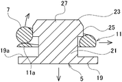
- FIG. 3A is a cross-sectional view showing the sheet member attached to the coil spring
- FIG. 3B is a cross-sectional view showing the dimensions of each part.
- sectional drawing which shows the motion of the strand of a coil spring at the time of axial direction omission.
- FIG. 6A is a cross-sectional view showing a sheet member attached to a coil spring
- FIG. 6B is a cross-sectional view showing a sheet member attached to a coil spring
- 6B is a cross-sectional view showing dimensions of each part according to the second embodiment of the present invention. It is principal part sectional drawing of the sheet
- the axial direction of the diameter-enlarged portion of the sheet member is to suppress the fall of the sheet member while suppressing damage to the coil spring at the time of press-fitting the diameter-enlarged portion of the sheet member and interference with the coil spring after the press-fit. Realized by setting the length.
- the outer diameter of the enlarged diameter portion is set larger than the inner diameter of the end winding portion, and at least the maximum diagonal length of the seat member is between the strands.
- the axial length of the enlarged diameter portion is set so as to be larger than the distance.
- the inter-element distance is the distance connecting the innermost diameter points at the positions of the 0.5 and 1.0 turns of the end winding in the winding direction of the coil spring element.
- the length in the diagonal direction is the wire when the portion where the side surface of the enlarged diameter portion intersects the bottom surface of the enlarged diameter portion and the mounting shaft portion on the outer circumference of the 0.5th strand of the end winding portion
- the enlarged diameter portion is provided on the tip side of the enlarged diameter portion with respect to the linear portion having a side surface extending linearly along the axial direction of the coil spring, and the side surface is chamfered or tapered.
- the axial direction length of a linear part it is preferable to make the axial direction length of a linear part longer than the axial direction length of a front-end
- the axial length of the straight portion may be 0.5 times or more the short diameter of the coil spring wire.
- the cross-sectional shape of the wire may be a cross-sectional oval shape in addition to a circular cross-section.
- the cross-sectional oval shape may be formed by a semicircular section having a strand on the outer diameter side of the coil.
- the outer diameter of the enlarged diameter portion may be set smaller than the distance between the strands of the end winding portion.
- the coil spring is a transition portion in which the end winding portion is reduced in diameter relative to the main body portion to be formed up to the first turn, and the diameter gradually increases from the end winding portion to the main body portion between the main body portion and the end winding portion.
- the mounting shaft portion has a gap between the seat member and the enlarged diameter portion of the seat member in a free state in which the end winding portion is fitted and the seat surface of the end winding portion is in contact with the receiving surface of the seat portion.
- the sheet member may be configured to have a hole extending in the axial direction from the tip of the enlarged diameter portion.
- the hole may be a bottomed hole.
- [Coil spring] 1 is an exploded side view of a coil spring and a sheet member of a coil spring assembly according to Embodiment 1 of the present invention
- FIG. 2 is an enlarged side view of the sheet member
- FIG. 3A is a coil spring.
- FIG. 3B is a chart showing the dimensions of each part.
- the coil spring assembly 1 shown in FIGS. 1 to 3 is used for, for example, an automobile transmission damper.
- the coil spring assembly 1 includes a coil spring 3 and a sheet member 5.
- the coil spring 3 is formed by winding the wire 7 in a coil shape.
- the material of the strand 7 is not specifically limited, For example, it is a high-strength material of the silicon chrome steel oil temper wire (SWOSC) for springs.
- the strand 7 of the present embodiment is circular in a cross section that intersects the winding direction (or circumferential direction) and is along the radial direction. Thereby, as for the strand 7, the diameter T of the coil spring 3 becomes a short diameter.
- the cross-sectional shape of the strand 7 may be an ellipse or an elliptical shape on one of the inner diameter side and the outer diameter side (see Example 3).
- the coil spring 3 includes end winding portions 11 and 13 at both ends of the main body portion 9.
- the end turns 11 and 13 are each reduced in diameter relative to the main body 9, and are formed from the end, which is the 0th turn of the coil spring 3, to the first turn.
- the seat surfaces 11a and 13a of the end winding portions 11 and 13 are provided in a range of 180 ° or more in the winding direction of the coil spring 3 and usually 270 ° (3/4 winding) from the tip. Therefore, the end turns 11 and 13 can be seated with the seating surfaces 11a and 13a stably contacting a receiving surface of the sheet member 5 described later.
- the material of the sheet member 5 is not particularly limited, but is obtained by subjecting an iron-based material to carbonitriding and quenching and tempering.
- an iron-based material for example, carbon steel for machine structure (S45C, S60C, etc.), header (For cold heading) It is made of carbon steel (SWCH) or the like.
- a pair of the sheet members 5 are provided, for example, and are attached to the both ends winding portions 11 and 13 so as to be rotatable about the axis.
- FIG. 1 only the sheet member 5 on one end winding part 11 side is shown and described.
- the sheet member 5 on the other end winding part 13 side has the same configuration as the sheet member 5 on the end winding part 11 side, and its mounting structure is the same as that on the end winding part 11 side.
- the sheet member 5 has a seat portion 19, a mounting shaft portion 21, and a diameter-expanded portion 23.
- the seat 19 is formed in a circular shape and has a receiving surface 19a.
- the outer diameter of the seat portion 19 is the same as or slightly larger or smaller than the outer diameter D of the end winding portion 11. Thereby, the seat part 19 can be made to contact
- the mounting shaft portion 21 is formed so as to protrude concentrically from the receiving surface 19 a of the seat portion 19, and an enlarged diameter portion 23 is formed at the tip of the mounting shaft portion 21 for a press-fitting guide. Details of the enlarged diameter portion 23 will be described later.
- the attachment shaft portion 21 is in a free state in which the end turn portion 11 is fitted and the seat surface 11a of the end turn portion 11 is in contact with the receiving surface 19a of the seat portion 19, and the diameter of the end turn portion 11 and the seat member 5 is increased. There is a gap between the portions 23 or the axial length at which the gap is zero.
- the fitting of the end turn part 11 to the attachment shaft part 21 is performed by the end turn part 11 formed by the first winding of the coil spring 3 orbiting the entire circumference of the attachment shaft part 21. Moreover, the end winding part 11 is arrange
- the axial clearance between the end turn part 11 and the enlarged diameter part 23 may be such that the end turn part 11 does not contact the enlarged diameter part 23, and need not be unnecessarily vacant.
- the state in which the gap is zero means a state in which the end turn part 11 is in contact with the enlarged diameter part 23 but no stress acts on the end turn part 11.
- the transition portion 15 is set so as to bypass the enlarged diameter portion 23 in a state where the seat surface 11a of the end winding portion 11 is in contact with the receiving surface 19a of the seat portion 19 and the transition portion 15 does not contact the enlarged diameter portion 23. ing.
- This detouring is performed such that the transition part 15 gradually expands the spiral from the end turn part 11 to the main body part 9. Even if the end turn part 11 is relatively moved in the radial direction of the attachment shaft part 21 by this detour, the transition part 15 does not contact the enlarged diameter part 23 or the gap becomes zero.
- the enlarged diameter portion 23 of the sheet member 5 is formed in a columnar shape whose diameter is increased with respect to the mounting shaft portion 21.
- the enlarged diameter portion 23 of this embodiment is composed of a straight portion 25 and a tip portion 27.
- the straight portion 25 has a side surface 25 a that extends linearly along the axial direction of the coil spring 3, and defines an outer diameter a of the enlarged diameter portion 23.
- the outer diameter a of the enlarged diameter portion 23 is larger than the inner diameter d of the end turn portion 11 and has a press-fitting allowance.
- the distal end portion 27 is provided on the distal end side in the axial direction with respect to the linear portion 25, and the side surface 27a is formed in a chamfered shape or a tapered shape.
- the chamfered or tapered side surface 27a is a square surface, but a round surface or the like can also be used.
- the enlarged diameter portion 23 has an outer diameter a larger than the inner diameter d of the end winding portion 11, and at least a maximum diagonal length Smax from the inter-element distance A.
- the axial length ta of the coil spring 3 is set so as to be larger.
- the outer diameter a of the enlarged diameter portion 23 of the present embodiment is set to be smaller than the inter-wire distance A of the end turn portion 11.
- the outer diameter “a” can be set larger than the inter-wire distance A of the end turn portion 11.
- the inter-element distance A is a distance connecting the innermost diameter points at the positions of the 0.5th and 1.0th turns of the end turn part 11 in the winding direction of the element 7 of the coil spring 3.
- the innermost point refers to the innermost portion of the outer periphery of the 0.5th and 1.0th turns in the radial direction in the cross section along the axial direction of the coil spring 3.
- d is the inner diameter of the end winding portion 11 of the coil spring 3
- r is the radius of the strand 7.
- the diagonal length S is the portion where the side surface 25a of the enlarged diameter portion 23 and the bottom surface 25b of the enlarged diameter portion 23 intersect on the outer periphery of the 0.5-th strand of the end winding portion 11 and the mounting shaft portion 21.
- the first point where the outer periphery of the wire 7 and the mounting shaft 21 come into contact with each other, the straight line passing through the first point and intersecting the central axis of the sheet member 5, and the side surface 25a of the enlarged diameter portion 23 Is a length connecting a second point (hereinafter referred to as a diagonal point) where
- the maximum diagonal length Smax is a length when the diagonal length S is maximum.
- the diagonal length S is maximized when the diagonal point is located at the upper end of the straight portion 25. (Hereinafter, this length is referred to as the maximum diagonal length Smax1.)
- the diagonal point of the maximum diagonal direction length Smax may not be located at the upper end of the linear portion 25.
- the maximum diagonal length Smax (Smax1) is set to be larger than the inter-element distance A as described above, but the diagonal length S is the maximum diagonal length Smax.
- a shorter part may be set to be larger than the inter-element distance A.
- the maximum diagonal direction length Smax1 is expressed by the following equation (2).
- b is the outer diameter of the mounting shaft portion 21.
- p is the distance from the lower end of the side surface 25a of the enlarged diameter portion 23 to the horizontal line passing through the center of the 0.5th roll, and is expressed by the following equation (3).
- the diagonal length Smax1 is expressed by the following equation (4) from the equations (2) and (3).
- the outer diameter a of the enlarged diameter portion 23 is preferably as large as possible in order to increase the above-described press-fitting allowance (outer diameter a of the enlarged diameter portion 23 ⁇ inner diameter d of the end wound portion 11). In consideration of interference with the coil spring 3 after the press-fitting of the coil spring 3, it is better to make it as large as possible within a range where the outer diameter a of the enlarged diameter portion 23 ⁇ the distance A between the strands.
- the axial length ta of the enlarged diameter portion 23 is set to be larger than the minor diameter T of the element wire 7 of the coil spring 3.
- the diameter is expanded while satisfying the maximum diagonal length Smax (Smax1)> the inter-element distance A.
- the axial length ta of the portion 23 is suppressed.
- the axial direction length ts of the linear part 25 of a present Example shall be 0.5 times or more of the short diameter T of the strand 7 of the coil spring 3.
- the diameter-enlarged portion 23 of the sheet member 5 is press-fitted into the end turn portion 11 of the coil spring 3 as described above.
- the enlarged diameter portion 23 is inserted into the inner periphery of the end turn portion 11 while the end turn portion 11 is enlarged, and the outer diameter a of the enlarged diameter portion 23 is the distance between the strands of the end turn portion 11. Since it is set smaller than A, it is suppressed that the end winding part 11 carries out diameter expansion deformation
- the sheet member 5 is prevented from falling off from the end turn portion 11 in the axial direction by the press-fitting allowance of the enlarged diameter portion 23.
- the transition portion 15 is detoured so as to gradually expand the spiral from the end turn portion 11 to the main body portion 9, the end turn portion 11 is relatively moved in the radial direction of the attachment shaft portion 21. Also, the transition part 15 does not come into contact with the enlarged diameter part 23 or the gap becomes zero.
- the sheet member 5 can be rotated around the axis without applying a load to the transition portion 15 of the coil spring 3.
- the outer diameter a of the enlarged-diameter portion 23 is suppressed to be small, the contact of the transition portion 15 with the enlarged-diameter portion 23 can be reliably suppressed, and the transition portion 15 of the coil spring 3 can be surely performed. The load on can be suppressed.
- the posture of the end turn portion 11 can be stabilized, and the seat surface 11a of the end turn portion 11 can be set to the seat member 5. Can be stably brought into contact with the receiving surface 19a.
- the end winding part 11 is disposed so as to avoid a corner between the seat part 19 and the mounting shaft part 21 of the sheet member 5, so that the seat surface 11 a of the end winding part 11 can be more stably seated. It can be brought into contact with the receiving surface 19 a of the member 5.
- the corner part between the seat part 19 of the seat member 5 and the attachment shaft part 21 is not a right angle, it is configured to transition by a concave R part (concave curved surface) (not shown).
- a concave R part concave curved surface
- the axial length ts of the linear portion 25 of the sheet member 5 is 0.5 times or more the short diameter T of the element wire 7 of the coil spring 3, so that the sheet member 5 is removed from the coil spring 3. Even if a load acts so as to be pulled out in the axial direction, the sheet member 5 is prevented from falling off from the coil spring 3 (missing in the axial direction).
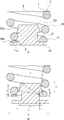
- FIG. 4 is a cross-sectional view showing the movement of the wire of the coil when the axial direction is removed
- FIG. 5 is a graph showing the change in the removal load when the axial length of the linear portion of the enlarged diameter portion is changed. .
- FIG. 5 is a plot of the unloading load against the axial length ts of the linear portion 25 in the three types of coil spring assemblies 1 in which the press-fitting allowances of the enlarged diameter portion 23 are 1.013, 1.015, and 1.019. It is a thing.
- the vertical axis represents the slip load
- the horizontal axis represents the axial length ts of the straight portion 25 as a ratio to the short diameter T of the element wire 7 of the coil spring 3.
- the press-fitting allowance in FIG. 5 is shown as a value obtained by dividing the outer diameter a of the enlarged diameter portion 23 by the inner diameter d of the coil spring 3.
- the unloading load required for the axial unloading gradually increases until the axial length ts / minor axis T becomes 0.26 to 0.5 in any press-fitting allowance, and the coil spring assembly 1, it becomes difficult for the sheet member 5 to gradually fall out in the axial direction.
- the slip-off load was flat at any press-fitting allowance. That is, when the axial length ts / minor axis T is 0.5 or more, the drop load drop due to the bending of the end turn portion 11 can be suppressed.
- the axial length ts of the enlarged diameter portion 23 is set in a range where the axial length ts / minor axis T is 0.5 or more.
- the seat member 5 includes the seat portion 19 in which the receiving surface 19 a abuts against the seat surface 11 a of the end winding portion 11, and the receiving surface 19 a of the seat portion 19.
- a protruding mounting shaft portion 21 and a diameter-increasing portion 23 for press-fitting guide formed at the tip of the mounting shaft portion 21 are provided.
- the outer diameter a of the enlarged diameter portion 23 is set to be larger than the inner diameter d of the end winding portion 11, and at least the maximum diagonal length Smax of the seat member 5 ( The axial length ta of the enlarged diameter portion 23 is set so that Smax1) is larger than the inter-element distance A.
- the maximum diagonal length Smax (Smax1) of the seat member 5 is greater than the inter-element distance A of the end turns 11. By being large, it is possible to prevent the sheet member 5 from missing in the rotational direction.
- the setting of the axial length ta of the enlarged-diameter portion 23 can suppress the increase in the outer diameter a of the enlarged-diameter portion 23 and suppress the rotational loss of the sheet member 5.
- the enlarged diameter portion 23 of the sheet member 5 is press-fitted into the end turn part 11, damage due to excessive deformation of the end turn part 11 can be suppressed.
- the increase in the outer diameter a of the enlarged diameter portion 23 can be suppressed in this way, interference with the end winding portion 11 of the coil spring 3 after press-fitting the enlarged diameter portion 23 of the seat member 5 can be suppressed.
- the load on the spring 3 can be suppressed.
- the posture of the coil spring 3 can be stabilized so that the seating surface 11 a of the end winding part 11 can be brought into stable contact with the receiving surface 19 a of the sheet member 5.
- the maximum diagonal length S is set to be greater than the inter-element distance A of the end winding portion 11.
- the axial length ts of the straight portion 25 is 0.5 times or more the short diameter T of the element wire 7 of the coil spring 3.
- the mounting shaft portion 21 of the sheet member 5 is in a free state in which the end turn portion 11 is fitted and the seat surface 11 a of the end turn portion 11 is in contact with the receiving surface 19 a of the seat portion 19.
- the enlarged diameter portion 23 is detoured in a state of being in contact with 19a.
- the load on the coil spring 3 can be more reliably suppressed by a synergistic effect with the setting of the outer diameter a of the enlarged diameter portion 23.
- FIG. 6A is a cross-sectional view showing a sheet member attached to the coil spring according to the coil spring assembly of Example 2, and FIG. 6B is a cross-sectional view showing dimensions of each part.
- the same reference numerals are given to the components corresponding to those in the first embodiment, and a duplicate description is omitted.
- the coil spring assembly 1 of the present embodiment is obtained by changing the shape of the enlarged diameter portion 23 of the sheet member 5 to a frustum shape with respect to the first embodiment. That is, the side surface 23a of the enlarged diameter portion 23 is formed in a tapered shape as a whole. According to this taper shape, the enlarged diameter portion 23 has the smallest outer diameter at the distal end portion and has an outer diameter a at the proximal end portion on the mounting shaft portion 21 side. In the present embodiment, the diagonal length S is maximized when the diagonal point is located at the upper end of the side surface 23a. Others are the same as in the first embodiment.
- FIG. 7 is a cross-sectional view of the main part of the sheet member attached to the coil spring, according to the coil spring assembly according to the third embodiment.
- the same reference numerals are given to the components corresponding to those in the first embodiment, and a duplicate description is omitted.
- the coil spring 3 of the present embodiment uses a strand 7 having an oval cross section instead of a strand having a circular cross section.
- the cross section of the coil inner diameter side portion 7a of the element wire 7 is constituted by, for example, a semi-elliptical shape portion
- the cross section of the coil outer diameter side portion 7b is constituted by a semicircular shape portion.
- the same effects as those of the first embodiment can be achieved.
- the coil outer diameter side portion 7b may be formed of a semi-elliptical portion
- the coil inner diameter side portion 7a may be formed of a semicircular shape portion.
- both the coil inner diameter side portion 7a and the coil outer diameter side portion 7b can be configured by a semi-elliptical shape portion, and can have an elliptical cross section as a whole.
- a semi-super-elliptical portion can be used instead of the semi-elliptical portion.
- FIG. 8 is a cross-sectional view of the sheet member according to the fourth embodiment.
- the same reference numerals are used for the components corresponding to those in the first embodiment, and a duplicate description is omitted.
- the sheet member 5 has a hole 29 extending in the axial direction from the tip of the enlarged diameter portion 23.
- the tip of the enlarged diameter portion 23 is a tip surface 27b.
- Others are the same as those in the first embodiment, but may be the same as those in the second or third embodiment.
- the planar shape of the hole 29 is circular. However, the planar shape of the hole 29 may be another geometric shape such as a rectangle. It is preferable that the diameter of the hole 29 and the length (depth) in the axial direction are maximized within a range in which the strength necessary for the sheet member 5 can be maintained.
- the hole portion 29 of the present embodiment is a bottomed hole, and is opened only on the distal end surface 27b of the enlarged diameter portion 23.
- the depth of the hole 29 corresponds to the sum of the lengths in the axial direction of the attachment shaft portion 21 and the enlarged diameter portion 23.
- the hole portion 29 has a bottom portion 29 a corresponding to the axial length (thickness) of the seat portion 19 of the seat member 5.
- the sheet member 5 can be reduced in weight by the hole 29.
- the axial length ta see FIG. 3
- an increase in the weight of the sheet member 5 can be suppressed.
- Example 4 since the hole part 29 is bottomed, the influence which it has on the contact state with the other member which the seat part 19 of the sheet
- FIG. 9 is a cross-sectional view of a sheet member according to a modification of the fourth embodiment.
- the hole 29 is a through hole penetrating in the axial direction of the sheet member 5.
- Others are the same as Example 4.
- Example 4 although the single hole part 29 was provided, you may provide a some hole part. In this case, a bottomed hole and a through hole may be mixed.
Landscapes
- Engineering & Computer Science (AREA)
- General Engineering & Computer Science (AREA)
- Mechanical Engineering (AREA)
- Physics & Mathematics (AREA)
- Acoustics & Sound (AREA)
- Aviation & Aerospace Engineering (AREA)
- Chemical & Material Sciences (AREA)
- Combustion & Propulsion (AREA)
- Transportation (AREA)
- Springs (AREA)
- Vibration Prevention Devices (AREA)
Abstract
Priority Applications (5)
| Application Number | Priority Date | Filing Date | Title |
|---|---|---|---|
| CN201980021623.8A CN111902652B (zh) | 2018-03-29 | 2019-03-26 | 盘簧组装体 |
| JP2020506368A JP6802412B2 (ja) | 2018-03-29 | 2019-03-26 | コイルばね組立体 |
| KR1020207022195A KR102408047B1 (ko) | 2018-03-29 | 2019-03-26 | 코일스프링조립체 |
| US16/982,738 US11339844B2 (en) | 2018-03-29 | 2019-03-26 | Coil spring assembly |
| EP19776906.0A EP3779232A4 (fr) | 2018-03-29 | 2019-03-26 | Ensemble ressort hélicoïdal |
Applications Claiming Priority (2)
| Application Number | Priority Date | Filing Date | Title |
|---|---|---|---|
| JP2018-065386 | 2018-03-29 | ||
| JP2018065386 | 2018-03-29 |
Publications (1)
| Publication Number | Publication Date |
|---|---|
| WO2019189281A1 true WO2019189281A1 (fr) | 2019-10-03 |
Family
ID=68058196
Family Applications (1)
| Application Number | Title | Priority Date | Filing Date |
|---|---|---|---|
| PCT/JP2019/013047 Ceased WO2019189281A1 (fr) | 2018-03-29 | 2019-03-26 | Ensemble ressort hélicoïdal |
Country Status (6)
| Country | Link |
|---|---|
| US (1) | US11339844B2 (fr) |
| EP (1) | EP3779232A4 (fr) |
| JP (2) | JP6802412B2 (fr) |
| KR (1) | KR102408047B1 (fr) |
| CN (1) | CN111902652B (fr) |
| WO (1) | WO2019189281A1 (fr) |
Cited By (1)
| Publication number | Priority date | Publication date | Assignee | Title |
|---|---|---|---|---|
| JP2023129126A (ja) * | 2022-03-04 | 2023-09-14 | 株式会社エクセディ | 回転装置 |
Families Citing this family (5)
| Publication number | Priority date | Publication date | Assignee | Title |
|---|---|---|---|---|
| CN112674543B (zh) * | 2019-10-17 | 2024-07-26 | 厦门新技术集成有限公司 | 用于家具的弹性模块和弹性垫 |
| KR102349748B1 (ko) * | 2020-08-12 | 2022-01-11 | 엘지전자 주식회사 | 밀폐형 압축기 |
| CN115251636A (zh) * | 2021-04-29 | 2022-11-01 | 厦门新技术集成有限公司 | 沙发床 |
| KR102587523B1 (ko) * | 2021-10-07 | 2023-10-10 | 전영환 | 판부재, 이를 이용한 smt용 탄성체 및 이의 제조방법 |
| CN113847359B (zh) * | 2021-12-01 | 2022-02-22 | 浙江铁流离合器股份有限公司 | 一种离合器从动盘扩充转角减振装置 |
Citations (6)
| Publication number | Priority date | Publication date | Assignee | Title |
|---|---|---|---|---|
| JPS6084832U (ja) * | 1983-11-17 | 1985-06-11 | 株式会社大金製作所 | ダンパ−デイスク |
| JPH01104719A (ja) * | 1987-07-10 | 1989-04-21 | Sugita Seisen Kojo:Kk | オイルテンパー硬引鋼線ばね及びその製造方法 |
| JP2007064345A (ja) | 2005-08-31 | 2007-03-15 | Suncall Corp | ダンパースプリング |
| WO2015194192A1 (fr) * | 2014-06-19 | 2015-12-23 | 日本発條株式会社 | Ensemble ressort hélicoïdal |
| JP2017087257A (ja) * | 2015-11-09 | 2017-05-25 | 松栄製鋲株式会社 | スプリングシートの製造方法、及び該スプリングシートの製造方法に用いられる転造用ダイス |
| JP2018044644A (ja) * | 2016-09-16 | 2018-03-22 | 日本発條株式会社 | ばねシート部材及びばね組立て体 |
Family Cites Families (15)
| Publication number | Priority date | Publication date | Assignee | Title |
|---|---|---|---|---|
| US3531069A (en) * | 1968-11-27 | 1970-09-29 | Gen Electric | Vibration mount for compressors and the like |
| US3901494A (en) * | 1973-10-29 | 1975-08-26 | Ernest H Sena | Auxiliary vehicle spring installation |
| DE2522841A1 (de) | 1975-05-23 | 1976-12-02 | Loehr & Bromkamp Gmbh | Anordnung einer ueber ein gleichlaufdrehgelenk antreibbaren radnabe |
| JPS5293866U (fr) * | 1976-01-07 | 1977-07-13 | ||
| KR920001611B1 (ko) | 1987-07-10 | 1992-02-20 | 가부시끼가이샤 스기타 세이센 고오죠오 | 스프링용 오일템퍼링 경화 인발강선 및 그 제조방법 |
| JPH08105479A (ja) * | 1994-10-05 | 1996-04-23 | Piolax Inc | ばね構造体 |
| DE19603248B4 (de) * | 1995-02-03 | 2011-09-22 | Schaeffler Technologies Gmbh & Co. Kg | Drehschwingungsdämpfer |
| JP2005313754A (ja) * | 2004-04-28 | 2005-11-10 | Togo Seisakusho Corp | サスペンション内蔵ホイール組立体 |
| JP2006037976A (ja) * | 2004-07-22 | 2006-02-09 | Aisin Aw Industries Co Ltd | ロックアップダンパのダンパスプリング用先端キャップ |
| SG157949A1 (en) * | 2004-07-28 | 2010-01-29 | Panasonic Refrigeration Device | System for reducing compressor noise and suspension spring and snubber arrangement therefor |
| US7370855B2 (en) * | 2005-01-25 | 2008-05-13 | Youd Jason B | Spring damper |
| US20080211156A1 (en) * | 2005-11-09 | 2008-09-04 | Check Ronald N | Spring damper |
| CN100497989C (zh) * | 2006-02-21 | 2009-06-10 | 东海橡胶工业株式会社 | 机动车悬架的弹簧座 |
| JP4699273B2 (ja) | 2006-04-27 | 2011-06-08 | 株式会社東郷製作所 | ばねシート部材及びばね組立て体 |
| DE112017003495T5 (de) | 2016-07-11 | 2019-05-02 | Schaeffler Technologies AG & Co. KG | Federendenabdeckung mit verbesserter Sicherung |
-
2019
- 2019-03-26 WO PCT/JP2019/013047 patent/WO2019189281A1/fr not_active Ceased
- 2019-03-26 EP EP19776906.0A patent/EP3779232A4/fr active Pending
- 2019-03-26 CN CN201980021623.8A patent/CN111902652B/zh active Active
- 2019-03-26 US US16/982,738 patent/US11339844B2/en active Active
- 2019-03-26 KR KR1020207022195A patent/KR102408047B1/ko active Active
- 2019-03-26 JP JP2020506368A patent/JP6802412B2/ja active Active
-
2020
- 2020-11-26 JP JP2020195925A patent/JP2021028542A/ja active Pending
Patent Citations (6)
| Publication number | Priority date | Publication date | Assignee | Title |
|---|---|---|---|---|
| JPS6084832U (ja) * | 1983-11-17 | 1985-06-11 | 株式会社大金製作所 | ダンパ−デイスク |
| JPH01104719A (ja) * | 1987-07-10 | 1989-04-21 | Sugita Seisen Kojo:Kk | オイルテンパー硬引鋼線ばね及びその製造方法 |
| JP2007064345A (ja) | 2005-08-31 | 2007-03-15 | Suncall Corp | ダンパースプリング |
| WO2015194192A1 (fr) * | 2014-06-19 | 2015-12-23 | 日本発條株式会社 | Ensemble ressort hélicoïdal |
| JP2017087257A (ja) * | 2015-11-09 | 2017-05-25 | 松栄製鋲株式会社 | スプリングシートの製造方法、及び該スプリングシートの製造方法に用いられる転造用ダイス |
| JP2018044644A (ja) * | 2016-09-16 | 2018-03-22 | 日本発條株式会社 | ばねシート部材及びばね組立て体 |
Non-Patent Citations (1)
| Title |
|---|
| See also references of EP3779232A4 |
Cited By (1)
| Publication number | Priority date | Publication date | Assignee | Title |
|---|---|---|---|---|
| JP2023129126A (ja) * | 2022-03-04 | 2023-09-14 | 株式会社エクセディ | 回転装置 |
Also Published As
| Publication number | Publication date |
|---|---|
| JP2021028542A (ja) | 2021-02-25 |
| JPWO2019189281A1 (ja) | 2020-05-28 |
| US20210003184A1 (en) | 2021-01-07 |
| US11339844B2 (en) | 2022-05-24 |
| EP3779232A1 (fr) | 2021-02-17 |
| KR102408047B1 (ko) | 2022-06-13 |
| JP6802412B2 (ja) | 2020-12-16 |
| CN111902652B (zh) | 2022-10-21 |
| EP3779232A4 (fr) | 2022-01-05 |
| CN111902652A (zh) | 2020-11-06 |
| KR20200100194A (ko) | 2020-08-25 |
Similar Documents
| Publication | Publication Date | Title |
|---|---|---|
| WO2019189281A1 (fr) | Ensemble ressort hélicoïdal | |
| JP6499648B2 (ja) | コイルばね組立体 | |
| JP2007506925A (ja) | パイプジョイント用の、中心でねじられることが可能な圧縮リング | |
| JP5761970B2 (ja) | プーリ構造体 | |
| JP4046010B2 (ja) | ダイナミックダンパ | |
| JP5900646B2 (ja) | ステアリング装置 | |
| JP6187635B2 (ja) | ステアリング装置 | |
| EP1213502A1 (fr) | Joint universel | |
| EP3161333B1 (fr) | Dispositif de retenue pour arbres intérieur et extérieur | |
| JP4467502B2 (ja) | トルクリミッタ | |
| JP4467503B2 (ja) | トルクリミッタ | |
| JP2007327593A (ja) | 自在継手、車両用操舵装置、及び自在継手の製造方法 | |
| US20250251015A1 (en) | Spring and socket joint | |
| JP2007010086A (ja) | 等速自在継手 | |
| CN108425976A (zh) | 板簧 | |
| JP2002181083A (ja) | 軸 受 | |
| JP2017180765A (ja) | プラグ圧入による封止構造 | |
| JP4558530B2 (ja) | トルクリミッタ | |
| JP2002235770A (ja) | 十字軸継手 | |
| JP2012192909A (ja) | スタビライザブッシュ | |
| JP2007100966A (ja) | 十字軸継手 | |
| JP2007100966A5 (fr) | ||
| JP2009030622A (ja) | バンドクリップ | |
| JP2013100656A (ja) | ドアヒンジ |
Legal Events
| Date | Code | Title | Description |
|---|---|---|---|
| 121 | Ep: the epo has been informed by wipo that ep was designated in this application |
Ref document number: 19776906 Country of ref document: EP Kind code of ref document: A1 |
|
| ENP | Entry into the national phase |
Ref document number: 2020506368 Country of ref document: JP Kind code of ref document: A |
|
| ENP | Entry into the national phase |
Ref document number: 20207022195 Country of ref document: KR Kind code of ref document: A |
|
| NENP | Non-entry into the national phase |
Ref country code: DE |
|
| WWE | Wipo information: entry into national phase |
Ref document number: 2019776906 Country of ref document: EP |
|
| ENP | Entry into the national phase |
Ref document number: 2019776906 Country of ref document: EP Effective date: 20201029 |