WO2019189334A1 - Fibre de charge, filtre de charge, matériau adsorbant de substance et machine de purification d'air - Google Patents
Fibre de charge, filtre de charge, matériau adsorbant de substance et machine de purification d'air Download PDFInfo
- Publication number
- WO2019189334A1 WO2019189334A1 PCT/JP2019/013140 JP2019013140W WO2019189334A1 WO 2019189334 A1 WO2019189334 A1 WO 2019189334A1 JP 2019013140 W JP2019013140 W JP 2019013140W WO 2019189334 A1 WO2019189334 A1 WO 2019189334A1
- Authority
- WO
- WIPO (PCT)
- Prior art keywords
- piezoelectric
- fiber
- charging
- filter
- generates
- Prior art date
- Legal status (The legal status is an assumption and is not a legal conclusion. Google has not performed a legal analysis and makes no representation as to the accuracy of the status listed.)
- Ceased
Links
Images


Classifications
-
- B—PERFORMING OPERATIONS; TRANSPORTING
- B01—PHYSICAL OR CHEMICAL PROCESSES OR APPARATUS IN GENERAL
- B01D—SEPARATION
- B01D39/00—Filtering material for liquid or gaseous fluids
- B01D39/14—Other self-supporting filtering material ; Other filtering material
- B01D39/16—Other self-supporting filtering material ; Other filtering material of organic material, e.g. synthetic fibres
- B01D39/1607—Other self-supporting filtering material ; Other filtering material of organic material, e.g. synthetic fibres the material being fibrous
- B01D39/1623—Other self-supporting filtering material ; Other filtering material of organic material, e.g. synthetic fibres the material being fibrous of synthetic origin
-
- B—PERFORMING OPERATIONS; TRANSPORTING
- B01—PHYSICAL OR CHEMICAL PROCESSES OR APPARATUS IN GENERAL
- B01D—SEPARATION
- B01D39/00—Filtering material for liquid or gaseous fluids
- B01D39/10—Filter screens essentially made of metal
-
- B—PERFORMING OPERATIONS; TRANSPORTING
- B01—PHYSICAL OR CHEMICAL PROCESSES OR APPARATUS IN GENERAL
- B01D—SEPARATION
- B01D39/00—Filtering material for liquid or gaseous fluids
- B01D39/14—Other self-supporting filtering material ; Other filtering material
- B01D39/20—Other self-supporting filtering material ; Other filtering material of inorganic material, e.g. asbestos paper, metallic filtering material of non-woven wires
- B01D39/2068—Other inorganic materials, e.g. ceramics
- B01D39/2082—Other inorganic materials, e.g. ceramics the material being filamentary or fibrous
-
- B—PERFORMING OPERATIONS; TRANSPORTING
- B03—SEPARATION OF SOLID MATERIALS USING LIQUIDS OR USING PNEUMATIC TABLES OR JIGS; MAGNETIC OR ELECTROSTATIC SEPARATION OF SOLID MATERIALS FROM SOLID MATERIALS OR FLUIDS; SEPARATION BY HIGH-VOLTAGE ELECTRIC FIELDS
- B03C—MAGNETIC OR ELECTROSTATIC SEPARATION OF SOLID MATERIALS FROM SOLID MATERIALS OR FLUIDS; SEPARATION BY HIGH-VOLTAGE ELECTRIC FIELDS
- B03C3/00—Separating dispersed particles from gases or vapour, e.g. air, by electrostatic effect
- B03C3/28—Plant or installations without electricity supply, e.g. using electrets
-
- B—PERFORMING OPERATIONS; TRANSPORTING
- B03—SEPARATION OF SOLID MATERIALS USING LIQUIDS OR USING PNEUMATIC TABLES OR JIGS; MAGNETIC OR ELECTROSTATIC SEPARATION OF SOLID MATERIALS FROM SOLID MATERIALS OR FLUIDS; SEPARATION BY HIGH-VOLTAGE ELECTRIC FIELDS
- B03C—MAGNETIC OR ELECTROSTATIC SEPARATION OF SOLID MATERIALS FROM SOLID MATERIALS OR FLUIDS; SEPARATION BY HIGH-VOLTAGE ELECTRIC FIELDS
- B03C3/00—Separating dispersed particles from gases or vapour, e.g. air, by electrostatic effect
- B03C3/34—Constructional details or accessories or operation thereof
- B03C3/40—Electrode constructions
- B03C3/41—Ionising-electrodes
-
- H—ELECTRICITY
- H10—SEMICONDUCTOR DEVICES; ELECTRIC SOLID-STATE DEVICES NOT OTHERWISE PROVIDED FOR
- H10N—ELECTRIC SOLID-STATE DEVICES NOT OTHERWISE PROVIDED FOR
- H10N30/00—Piezoelectric or electrostrictive devices
- H10N30/30—Piezoelectric or electrostrictive devices with mechanical input and electrical output, e.g. functioning as generators or sensors
-
- H—ELECTRICITY
- H10—SEMICONDUCTOR DEVICES; ELECTRIC SOLID-STATE DEVICES NOT OTHERWISE PROVIDED FOR
- H10N—ELECTRIC SOLID-STATE DEVICES NOT OTHERWISE PROVIDED FOR
- H10N30/00—Piezoelectric or electrostrictive devices
- H10N30/702—Piezoelectric or electrostrictive devices based on piezoelectric or electrostrictive fibres
-
- H—ELECTRICITY
- H10—SEMICONDUCTOR DEVICES; ELECTRIC SOLID-STATE DEVICES NOT OTHERWISE PROVIDED FOR
- H10N—ELECTRIC SOLID-STATE DEVICES NOT OTHERWISE PROVIDED FOR
- H10N30/00—Piezoelectric or electrostrictive devices
- H10N30/80—Constructional details
- H10N30/85—Piezoelectric or electrostrictive active materials
- H10N30/857—Macromolecular compositions
-
- B—PERFORMING OPERATIONS; TRANSPORTING
- B01—PHYSICAL OR CHEMICAL PROCESSES OR APPARATUS IN GENERAL
- B01D—SEPARATION
- B01D2239/00—Aspects relating to filtering material for liquid or gaseous fluids
- B01D2239/02—Types of fibres, filaments or particles, self-supporting or supported materials
- B01D2239/0241—Types of fibres, filaments or particles, self-supporting or supported materials comprising electrically conductive fibres or particles
-
- B—PERFORMING OPERATIONS; TRANSPORTING
- B01—PHYSICAL OR CHEMICAL PROCESSES OR APPARATUS IN GENERAL
- B01D—SEPARATION
- B01D2239/00—Aspects relating to filtering material for liquid or gaseous fluids
- B01D2239/06—Filter cloth, e.g. knitted, woven non-woven; self-supported material
- B01D2239/065—More than one layer present in the filtering material
-
- F—MECHANICAL ENGINEERING; LIGHTING; HEATING; WEAPONS; BLASTING
- F24—HEATING; RANGES; VENTILATING
- F24F—AIR-CONDITIONING; AIR-HUMIDIFICATION; VENTILATION; USE OF AIR CURRENTS FOR SCREENING
- F24F13/00—Details common to, or for air-conditioning, air-humidification, ventilation or use of air currents for screening
- F24F13/28—Arrangement or mounting of filters
-
- F—MECHANICAL ENGINEERING; LIGHTING; HEATING; WEAPONS; BLASTING
- F24—HEATING; RANGES; VENTILATING
- F24F—AIR-CONDITIONING; AIR-HUMIDIFICATION; VENTILATION; USE OF AIR CURRENTS FOR SCREENING
- F24F8/00—Treatment, e.g. purification, of air supplied to human living or working spaces otherwise than by heating, cooling, humidifying or drying
- F24F8/10—Treatment, e.g. purification, of air supplied to human living or working spaces otherwise than by heating, cooling, humidifying or drying by separation, e.g. by filtering
Definitions
- the present invention relates to a charged fiber for charging a substance, a charging filter made of the charged fiber, a substance adsorbing material made of the charging filter and an adsorption filter, and an air cleaner.
- Patent Document 1 discloses an air cleaner in which a charged substance is adsorbed by an electrostatic force of an electret filter after the substance is charged by corona discharge.
- Patent Document 1 needs to include a large unit for corona discharge.
- an object of the present invention is to provide a charged fiber, a charged filter, a substance adsorbing material, and an air cleaner that do not require a large unit for corona discharge.
- the charged fiber of the present invention includes a polarization generating fiber that generates a positive potential or a negative potential generated on the surface by energy from the outside.
- the polarization generating fiber positively charges a substance that passes through the polarization generating fiber by a positive potential, or negatively charges a substance that passes through the polarization generating fiber by a negative potential.
- Polarization generating fibers that generate polarization by external energy include, for example, substances having a piezoelectric effect (PLA: Poly Lactic Acid), substances having a photoelectric effect, substances having a pyroelectric effect (for example, PVDF: Poly Vinylidene Di Fluoride). Or a substance that causes polarization due to a chemical change.
- Polarization-generating fibers made of these materials can charge the material while not requiring a large unit such as corona discharge.
- the air cleaner of Patent Document 1 needs to consume power for corona discharge.
- the polarization generating fiber is composed of a piezoelectric fiber, the piezoelectric fiber expands and contracts due to the flow of air. Therefore, the polarization generating fiber does not require power to generate a positive potential or a negative potential generated on the surface. is there.
- a substance can be charged while a large unit for corona discharge is not required.
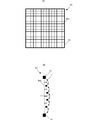
- FIG. 1 is a perspective view of a substance adsorbing material 100 including a charging filter 5 and an adsorption filter 20.
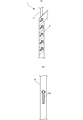
- FIG. 2A is a diagram illustrating a configuration of the piezoelectric yarn 1
- FIG. 2B is a plan view of the piezoelectric film 10.
- FIG. 3A and FIG. 3B are diagrams showing the relationship between the uniaxial stretching direction of polylactic acid, the electric field direction, and the deformation of the piezoelectric film 10.
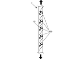
- FIG. 4 is a diagram showing the piezoelectric yarn 1 when an external force is applied.
- FIG. 5 is a diagram showing a configuration of the piezoelectric yarn 3.
- FIG. 6 is a diagram illustrating a configuration of the Z yarn (covering yarn) 1A.
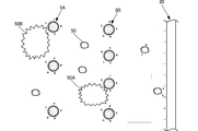
- FIG. 7 is a partial cross-sectional view of the charging filter 5 and the adsorption filter 20.
- FIG. 8 is a cross-sectional view of the charging filter 5.
- FIG. 9A is a cross-sectional view showing a state in which the adsorption filter 20 adsorbs the substance 50 charged to a positive potential
- FIG. 9B shows that the potential of the surface of the adsorption filter 20 is positive in a certain part.
- FIG. 9C is a cross-sectional view showing a state where the surface potential of the adsorption filter 20 becomes negative again.
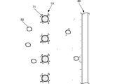
- FIG. 10 is a partial cross-sectional view of the first charging filter 5 ⁇ / b> A, the second charging filter 5 ⁇ / b> B, and the adsorption filter 20.
- FIG. 10 is a partial cross-sectional view of the first charging filter 5 ⁇ / b> A, the second charging filter 5 ⁇ / b> B, and the adsorption filter 20.
- FIG. 11 is a partial cross-sectional view of the piezoelectric yarn 1 ⁇ / b> A including the electrode 71 and the adsorption filter 20.
- FIG. 12A is a plan view of the charging filter 5C according to Modification Example 1
- FIG. 12B is a cross-sectional view of the charging filter 5C.
- FIG. 13A is a perspective view of a charging filter 5D according to Modification 2
- FIG. 13B is a cross-sectional view of the charging filter 5D.
- FIG. 14A is a plan view of the piezoelectric sheet 1D viewed in plan
- FIG. 14B is a back view.
- FIG. 15 is a partial cross-sectional view of the charging filter 51 and the adsorption filter 20.
- FIG. 1 is a perspective view of a substance adsorbing material 100 composed of a charging filter 5 and an adsorption filter 20.
- the substance adsorbing material 100 is used as a filter of an air cleaner, for example.
- the charging filter 5 includes a piezoelectric yarn 1 and a frame body 7.
- the plurality of piezoelectric yarns 1 are fixed to the frame body 7 at both ends in the axial direction.
- the plurality of piezoelectric yarns 1 are arranged in a lattice shape in a first direction (longitudinal direction) and in a second direction (lateral direction) orthogonal to the first direction.
- the arrangement of the piezoelectric yarns 1 is not limited to the mode shown in FIG.
- the piezoelectric yarns 1 may be arranged in an oblique direction, for example.
- the adsorption filter 20 includes, for example, an electret HEPA (High Efficiency Particulate Air) filter.
- the surface of the adsorption filter 20 is polarized to negative polarity or positive polarity.
- FIG. 2 (A) is a partially exploded view showing the configuration of the piezoelectric yarn 1
- FIG. 2 (B) is a plan view of the piezoelectric film 10.
- FIG. The piezoelectric yarn 1 is an example of a polarization generating fiber that generates polarization by external energy.
- the piezoelectric yarn 1 is formed by spirally turning a piezoelectric film 10 around a core yarn 11.
- the core yarn 11 is not an essential configuration. Even without the core yarn 11, it is possible to turn the piezoelectric film 10 in a spiral shape to obtain a piezoelectric yarn (swivel yarn).
- the swirl yarn is a hollow fiber. Further, when the swirl yarn itself is impregnated with an adhesive, the strength can be increased.
- the piezoelectric film 10 is made of, for example, a piezoelectric polymer.
- Piezoelectric polymers include those having pyroelectricity and those not having pyroelectricity.
- PVDF Poly Vinylidene Di Fluoride
- polylactic acid is a piezoelectric polymer that does not have pyroelectricity. Polylactic acid produces piezoelectricity by being uniaxially stretched. Polylactic acid includes PLLA in which an L monomer is polymerized and PDLA in which a D monomer is polymerized.
- Chiral polymers such as polylactic acid have a helical structure in the main chain.
- a chiral polymer has piezoelectricity when uniaxially stretched and the molecules are oriented.
- Piezoelectric film 10 made of uniaxially stretched polylactic acid has a thickness direction defined as a first axis, stretch direction 900 defined as a third axis, and a direction perpendicular to both the first axis and the third axis as a second axis.
- the piezoelectric strain constant has t14 components of d14 and d25. Therefore, polylactic acid generates polarization when distortion occurs in a direction of 45 degrees with respect to the uniaxially stretched direction.
- 3 (A) and 3 (B) are diagrams showing the relationship between the uniaxial stretching direction of polylactic acid, the electric field direction, and the deformation of the piezoelectric film 10.
- FIG. 3A when the piezoelectric film 10 contracts in the direction of the first diagonal 910A and extends in the direction of the second diagonal 910B orthogonal to the first diagonal 910A, the piezoelectric film 10 extends in the direction from the back side to the front side of the page. Generates an electric field. That is, the piezoelectric film 10 generates a negative potential on the front side of the paper.
- FIG. 3A when the piezoelectric film 10 contracts in the direction of the first diagonal 910A and extends in the direction of the second diagonal 910B orthogonal to the first diagonal 910A, the piezoelectric film 10 extends in the direction from the back side to the front side of the page. Generates an electric field. That is, the piezoelectric film 10 generates a negative potential on the front side of the paper.
- the piezoelectric film 10 is polarized in the case of extending in the direction of the first diagonal line 910A and contracting in the direction of the second diagonal line 910B, but the polarity is reversed and the surface of the paper surface An electric field is generated in the direction from the back to the back. That is, the piezoelectric film 10 generates a positive potential on the front side of the sheet.
- Polylactic acid generates piezoelectricity by molecular orientation treatment by stretching, and therefore does not need to be subjected to poling treatment like other piezoelectric polymers such as PVDF or piezoelectric ceramics.
- the piezoelectric constant of uniaxially stretched polylactic acid is about 5 to 30 pC / N, and has a very high piezoelectric constant among polymers. Furthermore, the piezoelectric constant of polylactic acid does not vary with time and is extremely stable.
- the piezoelectric film 10 is produced by cutting a uniaxially stretched polylactic acid sheet as described above to a width of about 0.5 to 2 mm, for example. As shown in FIG. 2B, the piezoelectric film 10 has a major axis direction and a stretching direction 900 that coincide with each other. As shown in FIG. 2A, the piezoelectric film 10 becomes a piezoelectric yarn 1 of a left turning yarn (hereinafter referred to as Z yarn) twisted by turning left with respect to the core yarn 11. The drawing direction 900 is inclined 45 degrees to the right with respect to the axial direction of the piezoelectric yarn 1.
- Z yarn left turning yarn
- the piezoelectric yarn 1 generates a positive potential on the surface when an external force is applied. Therefore, the piezoelectric yarn 1 generates a positive potential by external energy.
- FIG. 5 is a diagram showing a configuration of the piezoelectric yarn 3 of a right turning yarn (hereinafter referred to as S yarn). Since the piezoelectric yarn 3 is an S yarn, the stretching direction 900 is inclined 45 degrees to the left with respect to the axial direction of the piezoelectric yarn 3. Therefore, when an external force is applied to the piezoelectric yarn 3, the piezoelectric film 10 is in the state shown in FIG. 3B and generates a negative potential on the surface. Therefore, the piezoelectric yarn 3 generates a negative potential due to external energy.
- the piezoelectric yarn is manufactured by any known method.
- a method of extruding a piezoelectric polymer into a fiber a method of melt-spinning the piezoelectric polymer to make a fiber, a method of fiberizing the piezoelectric polymer by dry or wet spinning, or a piezoelectric polymer It is possible to adopt a technique for forming a fiber by electrostatic spinning.
- a Z yarn using PDLA is also conceivable.
- S yarn using PDLA is also conceivable as a yarn that generates a positive potential on the surface.
- the piezoelectric yarn may be one in which a piezoelectric body is discharged from a nozzle and stretched (piezoelectric yarn having a circular cross section).
- a Z yarn (covering yarn) 1A formed by twisting a piezoelectric yarn having a circular cross-section by turning to the left also generates a positive potential on the surface.
- a negative potential is generated on the surface of an S yarn formed by turning a piezoelectric yarn having a circular cross section to the right.
- the core yarn is not used, and it may be simply a twisted yarn.
- Such yarns can be made at low cost.
- the polarization generating fiber generates a positive potential or a negative potential generated on the surface by external energy.
- a polarization generating fiber functions as a charged fiber that charges a substance passing through the polarization generating fiber positively or negatively by a positive potential or a negative potential generated on the surface.
- the charging filter including the charging fiber charges a substance passing through the charging filter positively or negatively. In the example of FIG. 1, the substance passing through the charging filter 5 is positively charged.
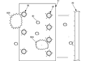
- FIG. 7 is a partial cross-sectional view of the charging filter 5 and the adsorption filter 20.
- a fan (not shown) in the air cleaner. The fan generates an air flow from the charging filter 5 toward the adsorption filter 20. Therefore, substances in the air (substance 50 and substance 50A in the drawing) move from the charging filter 5 toward the adsorption filter 20.
- FIG. 8 is a cross-sectional view of the charging filter 5.
- the piezoelectric yarns 1 are assembled in a lattice shape. Both ends of the piezoelectric yarn 1 are fixed to the frame body 7.
- the piezoelectric yarn 1 is arranged in a straight line between the frame bodies 7 as shown by the broken line in the figure.
- the piezoelectric yarn 1 extends so as to swell in a direction along the air flow at a position farthest from the frame body 7. Thereby, the piezoelectric yarn 1 extends along the axial direction. Therefore, a positive potential is generated on the surface of the piezoelectric yarn 1.
- the air flow is not uniform. Therefore, the piezoelectric yarn 1 is not uniformly stretched and changes every moment. Therefore, the polarization generated in the piezoelectric yarn 1 is not uniform. In addition, the stronger the air flow, the greater the amount of expansion of the piezoelectric yarn 1, and the more polarization is generated.
- the charging filter 5 supplements a substance 50 ⁇ / b> A that is larger than the joint of the charging filter 5. Further, the piezoelectric yarn 1 constituting the charging filter 5 generates a positive potential on the surface by the piezoelectric film 10. Therefore, the charging filter 5 charges the substance 50 passing through the charging filter 5 to a positive potential. The substance 50 is charged to the same potential (positive potential) as the surface of the charging filter 5 by contacting the charging filter 5. Alternatively, when the charging filter 5 has a potential high enough to release the charge into the air, the substance 50 can reach the same potential by approaching the surface of the charging filter 5 without contacting the surface of the charging filter 5. Charge to (positive potential).
- the substance 50 that has passed through the charging filter 5 reaches the adsorption filter 20 at the subsequent stage. Since the adsorption filter 20 is a very fine joint HEPA filter, it supplements the substance that has passed through the charging filter 5.
- the surface of the adsorption filter 20 has a negative potential.
- the adsorption filter 20 is made of, for example, a dielectric fiber (electret filter) whose surface is polarized to a negative potential. Accordingly, the substance 50 charged to a positive potential is adsorbed by the adsorption filter 20 at the subsequent stage. Therefore, the substance adsorbing material 100 including the charging filter 5 and the adsorption filter 20 exhibits a higher dust collecting force than the HEPA filter alone. In addition, the charging filter 5 exhibits higher dust collecting power because the generated polarization increases as the air flow becomes stronger. Thereby, the substance adsorption material 100 is suitable for using as a filter of an air cleaner.
- the adsorption filter 20 is an electret filter whose surface is negatively polarized. However, for example, even the piezoelectric yarn 3 shown in FIG. 5 generates a negative potential. The function of the adsorption filter 20 can be realized.
- the surface potential of the electret filter is neutralized, so that the adsorptive power may decrease as the amount of adsorbed substance increases.
- the generated potential does not change, so the adsorption force does not decrease.
- the piezoelectric yarn 1 and the piezoelectric yarn 3 are not uniformly stretched and change from moment to moment. Therefore, the polarization generated on the surface of the piezoelectric yarn 1 is not uniform, and a negative potential with a reverse polarity may be generated. Similarly, the piezoelectric yarn 3 may generate a positive potential. Therefore, the adsorption filter 20 using the piezoelectric yarn 1 or the piezoelectric yarn 3 may have a positive or negative surface potential. For example, as shown in FIG. 9A, after the adsorption filter 20 adsorbs the substance 50 charged to a positive potential, as shown in FIG. 9B, the surface potential of the adsorption filter 20 is at a certain portion.
- the substance 50 adsorbed on the surface is repelled and adsorbed at a site in the adsorption filter 20 where a negative potential is generated. Thereafter, as shown in FIG. 9C, when the surface potential of the adsorption filter 20 becomes negative, a substance having a positive potential can be adsorbed again.
- the suction filter 20 using the piezoelectric yarn 1 or the piezoelectric yarn 3 is less likely to reduce the suction force even if the amount of adsorption of the substance increases.
- the upstream charging filter 5 generates a positive potential and the downstream adsorption filter 20 generates a negative potential
- the upstream charging filter 5 generates a negative potential
- the material may be negatively charged, and the subsequent adsorption filter 20 may generate a positive potential.
- the charging filter 5 and the adsorption filter 20 do not have to be one each.
- the first charging filter 5A having a relatively coarse joint may be arranged at the front stage
- the second charging filter 5B having a relatively fine joint may be arranged at the rear stage.
- the substance 50B larger than the joint of the first charging filter 5A is supplemented by the first charging filter 5A in the previous stage. Since the substance 50B does not reach the second charging filter 5B, the second charging filter 5B can prevent clogging. Even if the substance 50B passes through the first charging filter 5A, the substance 50B is surely charged.
- FIG. 11 is a partial cross-sectional view of the piezoelectric yarn 1 ⁇ / b> A including the electrode 71 and the adsorption filter 20.
- the piezoelectric yarn 1A generates a positive potential on the surface like the piezoelectric yarn 1, but further includes an electrode 71 on the surface.
- the shape of the electrode 71 is, for example, a needle shape as shown in FIG. However, the shape of the electrode 71 is not limited to this example.
- the electrode 71 may have a thin film shape that covers a part of the surface of the piezoelectric yarn 1. Since the electrode 71 is a conductor, positive polarization generated on the surface of the piezoelectric yarn 1 is concentrated. Therefore, a locally high positive potential is generated on the surface of the electrode 71.
- the movement of electric charge is more likely to occur with respect to the substance 50 through the electrode 71.
- a higher potential is generated in the electrode 71, there is a possibility that a high potential is generated to the extent that charges can be released into the air. Therefore, the substance 50 is easily charged to the same potential (positive potential) by approaching the surface of the charging filter 5 without contacting the surface of the charging filter 5.
- FIG. 12A is a plan view of the charging filter 5C according to the first modification.
- FIG. 12B is a cross-sectional view of the charging filter 5C.
- the frame body 7C includes a partition member 50C that partitions the inside of the frame body 7C in a lattice shape in plan view. Both ends of the plurality of piezoelectric yarns 1 are fixed to the partition member 50C (or the frame body 7C).
- the partition member 50C has a smaller cross-sectional area than the frame body 7C. Further, the partition member 50C is made of a material softer than the frame body 7C. Therefore, as shown in FIG. 12B, when the air flow is generated, the partition member 50C extends so as to swell toward the direction along the air flow at a position farthest from the frame 7C.
- the plurality of piezoelectric yarns 1 extend to the partition member 50C (or the frame body 7C) so as to swell toward the direction along the air flow between both ends. Thereby, each piezoelectric yarn 1 is deformed to the same extent. Therefore, a positive electric potential with uniform strength is generated on the surface of the piezoelectric yarn 1 as a whole.
- the partition member 50C may be made of metal (conductor). In the case of a conductor, the electric charge generated in each piezoelectric yarn 1 moves to the partition member 50C, and a more uniform potential is generated as a whole. In the first modification, the piezoelectric yarn generates a positive potential, but may generate a negative potential.
- FIG. 13A is a perspective view of the charging filter 5D according to the second modification.
- FIG. 13B is a cross-sectional view of the charging filter 5D.
- a plurality of piezoelectric sheets 1D are arranged in a lattice shape on a frame 7D.
- Each piezoelectric sheet 1D has both ends fixed to the frame body 7D.
- the piezoelectric sheet 1D has a certain width along the direction of air flow. Also in this case, as shown in FIG. 13B, when an air flow occurs, the plurality of piezoelectric sheets 1D extend so as to swell in a direction along the air flow.
- FIG. 14A is a plan view of the piezoelectric sheet 1D viewed in plan
- FIG. 14B is a back view.
- the first piezoelectric sheet 100D and the second piezoelectric sheet 200D are bonded together.
- the first piezoelectric sheet 100D is stretched in a 45 ° right direction with respect to the air flow direction.
- the second piezoelectric sheet 200D is also stretched in a 45 ° right direction with respect to the air flow direction. Accordingly, the piezoelectric sheet 1D generates a positive potential on both the front surface and the back surface.
- the piezoelectric sheet 1D since the piezoelectric sheet 1D has a width along the air flow direction, the area in contact with the substance is larger than that of the piezoelectric yarn. Therefore, the piezoelectric sheet 1D can more easily charge the substance.
- the charged fiber may be an embodiment composed of a piezoelectric fiber that generates a negative potential on the surface (for example, PLLA S yarn) and a piezoelectric fiber that generates a positive potential on the surface (for example, PLLA Z yarn).
- the charging filter 51 of FIG. 15 includes a first charging filter 5E and a second charging filter 5F.
- the first charging filter 5E generates a negative potential.
- the second charging filter 5F generates a positive potential.
- the substance 50B larger than the joint of the first charging filter 5E is supplemented by the first charging filter 5E in the previous stage.
- the substance 50 and the substance 50A passing through the first charging filter 5E are charged to a negative potential. Therefore, the substance 50 and the substance 50A passing through the first charging filter 5E are easily adsorbed by the second charging filter 5F at the subsequent stage.
- the substance 50 that cannot be adsorbed by the second charging filter 5F is charged to a positive potential. Therefore, the substance 50 that has passed through the second charging filter 5F is adsorbed by the subsequent adsorption filter 20.
- a piezoelectric fiber that generates a negative potential is disposed in the previous stage and a piezoelectric fiber that generates a positive potential is disposed in the subsequent stage.
- a piezoelectric fiber that generates a positive potential is disposed in the preceding stage.
- the adsorption filter 20 uses a piezoelectric fiber that generates a positive potential or an electret filter whose surface is polarized to a positive potential.
- both a piezoelectric fiber that generates a positive potential and a piezoelectric fiber that generates a negative potential may be disposed in one charging filter. That is, the charged fiber of the present invention may be a piezoelectric fiber having both a first piezoelectric fiber that generates a negative potential and a second piezoelectric fiber that generates a positive potential.
- the piezoelectric yarn is shown as the fiber that generates polarization by external energy.
- the fiber that generates electric potential by external energy may be a material having a photoelectric effect or a pyroelectric effect, for example.
- a substance having a potential for example, PVDF
- a substance that generates a potential by a chemical change and the like.
- a structure in which a conductor is used for the core yarn, an insulator is wound around the conductor, and electricity is caused to flow through the conductor to generate polarization is also a fiber that generates a potential, and a large unit such as corona discharge Is not necessary.
- the piezoelectric body generates an electric field due to the piezoelectric, and therefore does not require a power source.
- the lifetime of the piezoelectric body is long, and there is no change in the amount of polarization caused by the adsorption of the substance. Therefore, the adsorption power does not decrease as the substance adsorbs unlike the electret filter.
Landscapes
- Chemical & Material Sciences (AREA)
- Engineering & Computer Science (AREA)
- Chemical Kinetics & Catalysis (AREA)
- Ceramic Engineering (AREA)
- Mechanical Engineering (AREA)
- General Engineering & Computer Science (AREA)
- Combustion & Propulsion (AREA)
- Inorganic Chemistry (AREA)
- Life Sciences & Earth Sciences (AREA)
- Geology (AREA)
- Physics & Mathematics (AREA)
- Spectroscopy & Molecular Physics (AREA)
- Electrostatic Separation (AREA)
- Filtering Materials (AREA)
Abstract
Cette fibre de charge est pourvue d'une fibre de génération de polarisation (1) qui génère un potentiel positif ou un potentiel négatif sur une surface de celle-ci à l'aide d'énergie externe. La fibre de génération de polarisation (1) amène une substance qui passe à travers la fibre de génération de polarisation (1) à être chargée positivement en raison du potentiel positif, ou amène une substance qui passe à travers la fibre de génération de polarisation (1) à être chargée négativement en raison du potentiel négatif.
Priority Applications (2)
| Application Number | Priority Date | Filing Date | Title |
|---|---|---|---|
| JP2020509179A JP6747622B2 (ja) | 2018-03-28 | 2019-03-27 | 帯電繊維、帯電フィルタ、物質吸着材、および空気清浄機 |
| US16/891,144 US20200292206A1 (en) | 2018-03-28 | 2020-06-03 | Charging fiber, charging filter, substance attracting material, and air purifier |
Applications Claiming Priority (2)
| Application Number | Priority Date | Filing Date | Title |
|---|---|---|---|
| JP2018-062194 | 2018-03-28 | ||
| JP2018062194 | 2018-03-28 |
Related Child Applications (1)
| Application Number | Title | Priority Date | Filing Date |
|---|---|---|---|
| US16/891,144 Continuation US20200292206A1 (en) | 2018-03-28 | 2020-06-03 | Charging fiber, charging filter, substance attracting material, and air purifier |
Publications (1)
| Publication Number | Publication Date |
|---|---|
| WO2019189334A1 true WO2019189334A1 (fr) | 2019-10-03 |
Family
ID=68060280
Family Applications (1)
| Application Number | Title | Priority Date | Filing Date |
|---|---|---|---|
| PCT/JP2019/013140 Ceased WO2019189334A1 (fr) | 2018-03-28 | 2019-03-27 | Fibre de charge, filtre de charge, matériau adsorbant de substance et machine de purification d'air |
Country Status (3)
| Country | Link |
|---|---|
| US (1) | US20200292206A1 (fr) |
| JP (1) | JP6747622B2 (fr) |
| WO (1) | WO2019189334A1 (fr) |
Families Citing this family (5)
| Publication number | Priority date | Publication date | Assignee | Title |
|---|---|---|---|---|
| EP3595515A4 (fr) | 2017-03-14 | 2020-12-30 | University of Connecticut | Capteur de pression biodégradable |
| US11826495B2 (en) | 2019-03-01 | 2023-11-28 | University Of Connecticut | Biodegradable piezoelectric ultrasonic transducer system |
| US11745001B2 (en) | 2020-03-10 | 2023-09-05 | University Of Connecticut | Therapeutic bandage |
| WO2021193957A1 (fr) * | 2020-03-26 | 2021-09-30 | 株式会社村田製作所 | Fibre composite |
| US12491290B2 (en) | 2020-06-08 | 2025-12-09 | University Of Connecticut | Biodegradable piezoelectric composite materials |
Citations (4)
| Publication number | Priority date | Publication date | Assignee | Title |
|---|---|---|---|---|
| JP2004066806A (ja) * | 2002-05-20 | 2004-03-04 | Toyobo Co Ltd | 成形繊維状シート、及びフィルターユニット |
| WO2010147074A1 (fr) * | 2009-06-15 | 2010-12-23 | 株式会社村田製作所 | Feuille piézoélectrique, procédé de fabrication d'une feuille piézoélectrique, et appareil de fabrication |
| JP2017527706A (ja) * | 2014-08-26 | 2017-09-21 | スリーエム イノベイティブ プロパティズ カンパニー | ポリ乳酸繊維を含むスパンボンドウェブ |
| JP2017220658A (ja) * | 2016-06-06 | 2017-12-14 | 株式会社村田製作所 | 発電体、発電装置およびセンサ |
Family Cites Families (5)
| Publication number | Priority date | Publication date | Assignee | Title |
|---|---|---|---|---|
| JP4922482B2 (ja) * | 2000-12-28 | 2012-04-25 | マイクロストーン株式会社 | 圧電性ファイバおよび圧電性織物デバイス |
| KR100749772B1 (ko) * | 2002-12-23 | 2007-08-17 | 삼성전자주식회사 | 공기 정화기 |
| KR102123170B1 (ko) * | 2015-12-25 | 2020-06-26 | 미쯔이가가꾸가부시끼가이샤 | 압전 기재, 압전 직물, 압전 편물, 압전 디바이스, 힘 센서, 액추에이터 및 생체 정보 취득 디바이스 |
| CN107293639B (zh) * | 2016-03-31 | 2020-02-04 | 北京纳米能源与系统研究所 | 聚左旋乳酸纤维材料在压电器件中的应用 |
| JP6771310B2 (ja) * | 2016-05-06 | 2020-10-21 | 帝人フロンティア株式会社 | カバリング糸状圧電素子を用いたデバイス |
-
2019
- 2019-03-27 WO PCT/JP2019/013140 patent/WO2019189334A1/fr not_active Ceased
- 2019-03-27 JP JP2020509179A patent/JP6747622B2/ja active Active
-
2020
- 2020-06-03 US US16/891,144 patent/US20200292206A1/en not_active Abandoned
Patent Citations (5)
| Publication number | Priority date | Publication date | Assignee | Title |
|---|---|---|---|---|
| JP2004066806A (ja) * | 2002-05-20 | 2004-03-04 | Toyobo Co Ltd | 成形繊維状シート、及びフィルターユニット |
| WO2010147074A1 (fr) * | 2009-06-15 | 2010-12-23 | 株式会社村田製作所 | Feuille piézoélectrique, procédé de fabrication d'une feuille piézoélectrique, et appareil de fabrication |
| JP2017527706A (ja) * | 2014-08-26 | 2017-09-21 | スリーエム イノベイティブ プロパティズ カンパニー | ポリ乳酸繊維を含むスパンボンドウェブ |
| JP2017220658A (ja) * | 2016-06-06 | 2017-12-14 | 株式会社村田製作所 | 発電体、発電装置およびセンサ |
| WO2017212836A1 (fr) * | 2016-06-06 | 2017-12-14 | 株式会社村田製作所 | Fil de génération de charge pour une contre-mesure de bactéries, tissu pour une contre-mesure de bactéries, tissu, vêtement, élément médical, fil de génération de charge bioactive et fil de génération de charge pour une adsorption de substance |
Also Published As
| Publication number | Publication date |
|---|---|
| US20200292206A1 (en) | 2020-09-17 |
| JPWO2019189334A1 (ja) | 2020-07-30 |
| JP6747622B2 (ja) | 2020-08-26 |
Similar Documents
| Publication | Publication Date | Title |
|---|---|---|
| WO2019189334A1 (fr) | Fibre de charge, filtre de charge, matériau adsorbant de substance et machine de purification d'air | |
| EP3127593B1 (fr) | Toile de filtrage contenant des fibres fines et des particules expansibles | |
| JP5014353B2 (ja) | 改良されたフィルタ媒体による能動電界分極媒体型エアクリーナ | |
| US8252095B2 (en) | Filter media for active field polarized media air cleaner | |
| JP6689943B1 (ja) | 樹脂構造体 | |
| KR102541787B1 (ko) | 편광 공기 정화기용 파형화된 여과 미디어 | |
| CN109088563B (zh) | 碳纳米管纤维复合结构型电磁致动器 | |
| JP5647498B2 (ja) | 不織布製造装置、不織布の製造方法及び不織布 | |
| CN114728227A (zh) | 空气净化用过滤器 | |
| CN115666755A (zh) | 过滤复合材料 | |
| US10413856B2 (en) | Stacked body | |
| US20240116262A1 (en) | Waterproof sound-transmitting sheet and method for manufacturing waterproof sound-transmitting sheet | |
| JP5653775B2 (ja) | 不織布製造装置、不織布の製造方法及び不織布 | |
| JP4915329B2 (ja) | ナノファイバー及び高分子ウェブの製造方法と装置 | |
| JP5225885B2 (ja) | ナノファイバ製造装置、および製造方法 | |
| JP2018051548A (ja) | フィルタ | |
| CN106256403A (zh) | 层叠无纺布、空气净化机及层叠无纺布的制造方法 | |
| JP5475496B2 (ja) | 紡糸装置、不織布製造装置、不織布の製造方法及び不織布 | |
| JP2024532070A (ja) | 永久電気双極子を有するセパレータを備えるスーパーキャパシタ | |
| JP6890223B2 (ja) | 帯電繊維及び帯電繊維の製造方法 | |
| JP6471982B2 (ja) | 積層体およびその製造方法 | |
| JP2010133039A (ja) | ナノファイバ製造方法、および製造装置 | |
| KR20190123004A (ko) | 미세먼지 차단용 필터 제조 방법 | |
| JP5705667B2 (ja) | 繊維集合体の製造方法及び製造装置 | |
| JP2020170813A (ja) | 発電素子および発電素子の製造方法 |
Legal Events
| Date | Code | Title | Description |
|---|---|---|---|
| 121 | Ep: the epo has been informed by wipo that ep was designated in this application |
Ref document number: 19777030 Country of ref document: EP Kind code of ref document: A1 |
|
| ENP | Entry into the national phase |
Ref document number: 2020509179 Country of ref document: JP Kind code of ref document: A |
|
| NENP | Non-entry into the national phase |
Ref country code: DE |
|
| 122 | Ep: pct application non-entry in european phase |
Ref document number: 19777030 Country of ref document: EP Kind code of ref document: A1 |