WO2019189376A1 - Appareil à vide localisé, appareil à particules chargées et procédé de formation de zone sous vide - Google Patents
Appareil à vide localisé, appareil à particules chargées et procédé de formation de zone sous vide Download PDFInfo
- Publication number
- WO2019189376A1 WO2019189376A1 PCT/JP2019/013225 JP2019013225W WO2019189376A1 WO 2019189376 A1 WO2019189376 A1 WO 2019189376A1 JP 2019013225 W JP2019013225 W JP 2019013225W WO 2019189376 A1 WO2019189376 A1 WO 2019189376A1
- Authority
- WO
- WIPO (PCT)
- Prior art keywords
- vacuum
- space
- sample
- beam irradiation
- state
- Prior art date
- Legal status (The legal status is an assumption and is not a legal conclusion. Google has not performed a legal analysis and makes no representation as to the accuracy of the status listed.)
- Ceased
Links
Images


Classifications
-
- H—ELECTRICITY
- H01—ELECTRIC ELEMENTS
- H01J—ELECTRIC DISCHARGE TUBES OR DISCHARGE LAMPS
- H01J37/00—Discharge tubes with provision for introducing objects or material to be exposed to the discharge, e.g. for the purpose of examination or processing thereof
- H01J37/02—Details
- H01J37/18—Vacuum locks ; Means for obtaining or maintaining the desired pressure within the vessel
-
- H—ELECTRICITY
- H01—ELECTRIC ELEMENTS
- H01J—ELECTRIC DISCHARGE TUBES OR DISCHARGE LAMPS
- H01J37/00—Discharge tubes with provision for introducing objects or material to be exposed to the discharge, e.g. for the purpose of examination or processing thereof
- H01J37/02—Details
- H01J37/20—Means for supporting or positioning the object or the material; Means for adjusting diaphragms or lenses associated with the support
-
- H—ELECTRICITY
- H01—ELECTRIC ELEMENTS
- H01J—ELECTRIC DISCHARGE TUBES OR DISCHARGE LAMPS
- H01J37/00—Discharge tubes with provision for introducing objects or material to be exposed to the discharge, e.g. for the purpose of examination or processing thereof
- H01J37/26—Electron or ion microscopes; Electron or ion diffraction tubes
- H01J37/28—Electron or ion microscopes; Electron or ion diffraction tubes with scanning beams
Definitions
- the present invention relates to a technical field of, for example, a local vacuum device that forms a local vacuum region, a charged particle device that irradiates charged particles through the local vacuum region, and a method of forming a local vacuum region.
- Patent Document 1 describes a scanning electron microscope that forms a local vacuum region by blocking the periphery of an inspection target portion of a test object irradiated with an electron beam, which is an example of a charged particle, from outside air. ing.
- an apparatus further, an arbitrary apparatus for forming a vacuum region
- the vacuum forming member has a pipe line connectable to the exhaust device, discharges the gas in the space in contact with the surface of the object through the pipe line, and forms a vacuum region;
- An external surface located at least a part of the periphery of the object, and a position changing device that changes a relative position between the surface of the object and the external surface along a predetermined direction intersecting the surface of the object,
- a local vacuum device is provided in which at least a part of gas in a space having a higher atmospheric pressure than the vacuum region around the vacuum region is discharged through the pipe line of the vacuum forming member.
- the pipe has a first end connected to the exhaust device and a second end connected to the first space in contact with the surface of the object, and the gas in the first space is supplied to the pipe.
- a vacuum forming member that forms a vacuum region in the first space that is discharged through a path and has a lower pressure than the second space connected to the first space, and at least part of the periphery of the object
- a local vacuum apparatus is provided that includes an external surface and a position changing device that changes a relative position between the surface of the object and the external surface along a predetermined direction intersecting the surface of the object.
- the pipe has a pipe line connectable to the exhaust device, and the gas is discharged through the pipe line in a state of being opposed to a part of the plane of the object.
- a vacuum forming member capable of forming in the first space in contact with the first part a vacuum region having a pressure lower than the pressure in the second space in contact with the second part different from the first part of the surface;
- a local vacuum device comprising: an external surface located at least in part; and a position changing device that changes a relative position between the surface of the object and the external surface along a predetermined direction intersecting the surface of the object.
- the pipe has a pipe that can be connected to the exhaust device, and the gas in the space in contact with the face of the object is supplied to the pipe in a state where the face of the object and the end of the pipe face each other.
- a vacuum forming member that discharges through a path to form a vacuum region, an external surface located at least part of the periphery of the object, and a surface of the object along a predetermined direction intersecting the surface of the object
- a position changing device for changing the relative position between the outer surface and the external surface.
- the vacuum forming member has a pipe line connectable to the exhaust device, discharges the gas in the space in contact with the surface of the object through the pipe line, and forms a vacuum region;
- a holding device having a holding surface capable of holding an object; and an external surface located at least at a part of the periphery of the holding surface, and at least a part of a space having a higher atmospheric pressure than the vacuum region around the vacuum region.
- the gas is discharged through the conduit of the vacuum forming member, and the outer surface is directed from the holding surface to the surface of the object by a predetermined amount determined according to the standard value range of the thickness of the object.
- a local vacuum device is provided protruding in the direction from the holding surface.
- the gas in the space in contact with the surface of the object is discharged through the conduit to form the vacuum region, and the space having a higher atmospheric pressure than the vacuum region around the vacuum region. Exhausting at least a portion of the gas through the conduit and an external surface located on at least a portion of the surface of the object and the periphery of the object along a predetermined direction intersecting the surface of the object.
- a method of forming a vacuum region is provided that includes changing the relative position.
- a gas in one space is discharged through the pipe line to form a vacuum region in the first space having a lower pressure than the second space connected to the first space, and intersects the surface of the object
- a method of forming a vacuum region includes changing a relative position between a surface of the object and an outer surface located at least at a part of the periphery of the object along a predetermined direction.
- the first space of the surface is different from the first portion of the surface in the first space contacting the first portion of the surface of the object by discharging the gas through the conduit connectable with the exhaust device.
- Forming a vacuum region whose pressure is lower than the pressure of the second space in contact with the second part, and being located on at least a part of the surface of the object and the periphery of the object along a predetermined direction intersecting the surface of the object Changing the relative position of the external surface to be formed is provided.
- the gas in the space contacting the surface of the object is discharged through the pipe line.
- Forming a vacuum region, and changing a relative position of the surface of the object and an external surface located at least part of the periphery of the object along a predetermined direction intersecting the surface of the object A method of forming a vacuum region is provided.
- the vacuum forming member that covers a part of the surface of the object and can locally form a vacuum region in contact with the object
- the holding device having the holding surface that can hold the object, and the holding A position for changing a relative position between the surface of the object and the external surface along a predetermined direction intersecting the surface of the object held by the holding surface and at least a part of the periphery of the surface;
- a local vacuum device is provided comprising the changing device.
- a vacuum forming member capable of locally forming a vacuum region covering a part of the surface of the object in a space on the object, and a holding device having a holding surface capable of holding the object;
- An external surface located at least at a part of the periphery of the holding surface, and the external surface is directed from the holding surface to the surface of the object by a predetermined amount determined according to a standard value range of the thickness of the object.
- a local vacuum device is provided protruding in the direction from the holding surface.
- a method for forming a vacuum region includes changing a relative position between the surface of the object and an outer surface located at least part of the periphery of the holding surface along a predetermined direction.
- FIG. 1 is a cross-sectional view showing the structure of a scanning electron microscope.
- FIG. 2 is a cross-sectional view showing the structure of the beam irradiation device provided in the scanning electron microscope.
- FIG. 3 is a perspective view showing a structure of a beam irradiation device provided in the scanning electron microscope.
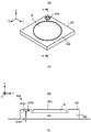
- 4A and 4B are cross-sectional views showing the structure of the stage provided in the scanning electron microscope, and
- FIG. 4C is a plan view showing the structure of the stage provided in the scanning electron microscope. is there.
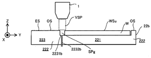
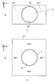
- FIG. 5A is a cross-sectional view showing a vacuum region formed between the beam irradiation apparatus and the sample
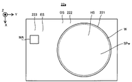
- FIG. 5B is a plan view showing a vacuum region formed between the beam irradiation apparatus and the sample.
- FIG. 5A is a cross-sectional view showing a vacuum region formed between the beam irradiation apparatus and the sample
- FIG. 5B is a plan view showing a vacuum region formed between the beam i
- FIG. 6A is a cross-sectional view showing a vacuum region formed by the beam irradiation apparatus near the boundary between the sample and the retracting member
- FIG. 6B shows the beam irradiation apparatus formed near the boundary between the sample and the retracting member. It is a top view which shows the vacuum area
- FIG. 7A is a cross-sectional view showing a vacuum region formed between the beam irradiation apparatus and the retracting member
- FIG. 7B shows a vacuum region formed between the beam irradiation apparatus and the retracting member.
- FIG. 8A to 8D is a cross-sectional view showing one step of an operation of maintaining a vacuum region using a retracting member when a sample held by a stage is carried in and out.
- FIG. 9A to FIG. 9D is a cross-sectional view showing one step of the operation of maintaining the vacuum region using the retracting member when the beam irradiation apparatus newly forms a vacuum region.
- FIG. 10 is a plan view showing the structure of the stage provided in the scanning electron microscope of the first modification.
- FIG. 11A to FIG. 11C is a plan view showing marks formed on the retracting member of the stage of the first modified example.
- FIG. 12A to FIG. 12D is a cross-sectional view showing one step of an operation of setting a scanning electron microscope using a mark.
- FIG. 13A is a cross-sectional view showing the structure of the stage according to the second modification
- FIG. 13B is a plan view showing the structure of the stage according to the second modification
- FIG. 14 is a cross-sectional view showing a vacuum region facing the space between the retracting member and the sample.
- FIG. 15 is a cross-sectional view showing another example of the structure of the stage of the second modified example.
- FIG. 16 is a plan view showing another example of the structure of the stage of the second modified example.
- FIG. 17A is a cross-sectional view showing a sample held on the stage in the third modification
- FIG. 17B is a plan view showing the sample held on the stage in the third modification.
- FIG. 18 is a cross-sectional view showing the structure of the beam irradiation apparatus of the fourth modification.
- FIG. 19 is a cross-sectional view showing the structure of the beam irradiation apparatus of the fourth modified example.
- FIG. 20 is a cross-sectional view showing the structure of the beam irradiation apparatus of the fifth modification.
- FIG. 21 is a cross-sectional view showing the structure of the stage provided in the scanning electron microscope according to the sixth modification.
- FIG. 22 is a cross-sectional view showing the positional relationship between the stage and the beam irradiation apparatus in the sixth modification.
- FIG. 23A and FIG. 23B is a cross-sectional view showing the structure of the stage provided in the scanning electron microscope in the seventh modification.
- FIG. 23A and FIG. 23B is a cross-sectional view showing the structure of the stage provided in the scanning electron microscope in the seventh modification.
- FIG. 24 is a cross-sectional view showing the structure of the stage provided in the scanning electron microscope according to the eighth modification.
- FIG. 25 is a cross-sectional view showing one step of the operation of the stage provided in the scanning electron microscope in the eighth modified example.
- FIG. 26 is a cross-sectional view showing one step of the operation of the stage provided in the scanning electron microscope in the eighth modified example.
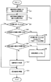
- FIG. 27 is a flowchart showing an operation flow for maintaining the vacuum region in the ninth modification.
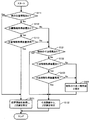
- FIG. 28 is a flowchart showing an operation flow for specifying the respective Z positions of the movement source surface and the movement destination surface in the ninth modification.
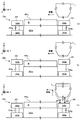
- 29A shows an example in which the surface of the sample that is the movement source surface is lower than the upper surface of the outer peripheral member that is the movement destination surface when the state of the beam irradiation apparatus is switched from the non-retraction state to the retraction state.
- 29B is a cross-sectional view, and FIG. 29B shows that when the state of the beam irradiation device is switched from the non-reserved state to the retracted state, the surface of the sample that is the movement source surface is from the upper surface of the outer peripheral member that is the movement destination surface.
- 29C is a cross-sectional view showing a higher example, and FIG.
- FIG. 29C shows a state between the beam irradiation apparatus and the surface of the sample that is the movement source surface when the state of the beam irradiation apparatus is switched from the non-reserved state to the retracted state. It is sectional drawing which shows the operation
- FIG. 30A shows an example in which the upper surface of the outer peripheral member that is the movement source surface is lower than the surface of the sample that is the movement destination surface when the state of the beam irradiation apparatus is switched from the retreat state to the non-retraction state.
- FIG. 30B is a cross-sectional view, and FIG.
- FIG. 30B shows that when the state of the beam irradiation device is switched from the retracted state to the non-retracted state, the upper surface of the outer peripheral member that is the movement source surface is greater than the surface of the sample that is the movement destination surface.
- FIG. 30C is a cross-sectional view showing a higher example, and FIG. 30C shows the relationship between the beam irradiation device and the upper surface of the outer peripheral member that is the movement source surface when the state of the beam irradiation device is switched from the retracted state to the non-retracted state. It is sectional drawing which shows the operation
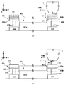
- FIG. 31A shows the outer peripheral member when the state of the beam irradiation device is switched from the non-reserved state to the retracted state under the condition that the surface of the sample that is the moving source surface is lower than the upper surface of the outer peripheral member that is the moving destination surface.
- FIG. 31B is a cross-sectional view showing the operation of moving the sample, and FIG. 31B shows that the state of the beam irradiation apparatus is non-evacuated under a situation where the surface of the sample as the movement source surface is higher than the upper surface of the outer peripheral member as the movement destination surface It is sectional drawing which shows the operation
- FIG. 32A shows the outer peripheral member when the state of the beam irradiation device is switched from the retracted state to the non-retracted state under the condition that the upper surface of the outer peripheral member that is the movement source surface is higher than the surface of the sample that is the movement destination surface.
- FIG. 32B is a sectional view showing the operation of moving the beam irradiation device in a state where the upper surface of the outer peripheral member which is the movement source surface is lower than the surface of the sample which is the movement destination surface. It is sectional drawing which shows the operation
- FIG. 33A is a perspective view showing the structure of the stage provided in the scanning electron microscope of the tenth modification, and FIG.
- FIG. 33B is a cross-sectional view taken along the line AA in FIG.
- FIG. 34A to FIG. 34D is a cross-sectional view showing one process of the operation of the scanning electron microscope of the tenth modification.
- FIGS. 35A and 35B are views showing the structure of the stage provided in the scanning electron microscope of the eleventh modification.
- FIG. 36 is a cross-sectional view showing the structure of the scanning electron microscope of the twelfth modification.
- FIG. 37 is a cross-sectional view showing the structure of a scanning electron microscope of the thirteenth modification.
- FIG. 38 is a cross-sectional view showing how the stage holds the sample in the fourteenth modification.
- FIG. 39 is a cross-sectional view showing how the stage holds the sample in the fifteenth modification.
- FIG. 40 is a cross-sectional view showing how the stage holds the sample in the sixteenth modification.
- FIG. 41A and FIG. 41B is a plan view showing another example of the structure of the stage provided in the scanning electron
- a scanning electron microscope Sccanning Electron Microscope
- Embodiments of a local vacuum apparatus, a charged particle apparatus, a vacuum region forming method, and a charged particle irradiation method will be described using SEM.
- the sample W is, for example, a semiconductor substrate. However, the sample W may be an object different from the semiconductor substrate.
- the sample W is, for example, a disk-shaped substrate having a diameter of about 300 millimeters and a thickness of about 750 micrometers to 800 micrometers.
- the sample W may be a substrate (or object) having an arbitrary size and an arbitrary shape.
- the sample W may be a square substrate for a display such as a liquid crystal display element or a square substrate for a photomask.
- each of the X-axis direction and the Y-axis direction is a horizontal direction (that is, a predetermined direction in the horizontal plane), and the Z-axis direction is a vertical direction (that is, a direction orthogonal to the horizontal plane). Yes, in the vertical direction).
- the + Z side corresponds to the upper side (that is, the upper side)
- the ⁇ Z side corresponds to the lower side (that is, the lower side).
- the Z-axis direction is also a direction parallel to an optical axis AX of a beam optical system 11 (described later) provided in the scanning electron microscope SEM. Further, the rotation directions around the X axis, the Y axis, and the Z axis (in other words, the tilt direction) are referred to as a ⁇ X direction, a ⁇ Y direction, and a ⁇ Z direction, respectively.
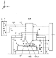
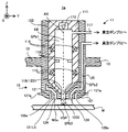
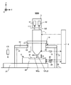
- FIG. 1 is a cross-sectional view showing the structure of a scanning electron microscope SEM.
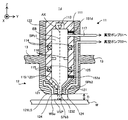
- FIG. 2 is a cross-sectional view showing the structure of the beam irradiation apparatus 1 provided in the scanning electron microscope SEM.
- FIG. 3 is a perspective view showing the structure of the beam irradiation apparatus 1 provided in the scanning electron microscope SEM.
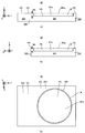
- 4A is a cross-sectional view showing the structure of the stage 22 included in the scanning electron microscope SEM
- FIG. 4B is a plan view showing the structure of the stage 22 included in the scanning electron microscope SEM.
- FIG. 1 does not show a cross section of some components of the scanning electron microscope SEM.
- the scanning electron microscope SEM includes a beam irradiation device 1, a stage device 2, a support frame 3, a control device 4, and a pump system 5. Further, the pump system 5 includes a vacuum pump 51 and a vacuum pump 52.
- the beam irradiation device 1 can emit an electron beam EB downward from the beam irradiation device 1.
- the beam irradiation apparatus 1 can irradiate the sample beam W held by the stage apparatus 2 disposed below the beam irradiation apparatus 1 with the electron beam EB.
- the beam irradiation apparatus 1 includes a beam optical system 11 and a differential pumping system 12 as shown in FIGS.
- the beam optical system 11 includes a housing 111.
- the casing 111 is a cylindrical member in which a beam passage space SPb1 extending along the optical axis AX of the beam optical system 11 (that is, extending along the Z axis) is secured.
- the beam passage space SPb1 is used as a space through which the electron beam EB passes.
- the housing 111 may be made of a high magnetic permeability material.
- the high magnetic permeability material is at least one of permalloy and silicon steel. The relative permeability of these high permeability materials is 1000 or more.
- the beam passage space SPb1 is a vacuum space during the period of irradiation with the electron beam EB.
- a pipe that is, a pipe formed in the casing 111 (and further, a side wall member 122 described later) is connected to the beam passage space SPb1 so as to communicate with the beam passage space SPb1 (that is, to be connected).
- Path The vacuum pump 51 is connected via the 117.
- the vacuum pump 51 exhausts the beam passage space SPb1 to reduce the pressure from the atmospheric pressure so that the beam passage space SPb1 becomes a vacuum space.
- the vacuum space in this embodiment may mean a space whose pressure is lower than atmospheric pressure.
- the vacuum space is a space in which gas molecules do not exist so much as to prevent proper irradiation of the sample W of the electron beam EB (in other words, a degree of vacuum that does not prevent appropriate irradiation of the sample W of the electron beam EB).
- Space The beam passage space SPb1 is a space outside the casing 111 (more specifically, a differential exhaust system 12 described later) via a beam emission port (that is, an opening) 119 formed on the lower surface of the casing 111. It communicates with the beam passage space SPb2).
- the beam passage space SPb1 may be a vacuum space during a period when the electron beam EB is not irradiated.
- the beam optical system 11 further includes an electron gun 113, an electromagnetic lens 114, an objective lens 115, and an electron detector 116.
- the electron gun 113 emits an electron beam EB toward the ⁇ Z side.
- a photoelectric conversion surface that emits electrons when irradiated with light may be used.
- the electromagnetic lens 114 controls the electron beam EB emitted from the electron gun 113.
- the electromagnetic lens 114 has a rotation amount of an image (that is, a position in the ⁇ Z direction) formed on a predetermined optical surface (for example, a virtual surface intersecting the optical path of the electron beam EB), and a magnification of the image. And any one of the focal positions corresponding to the imaging positions may be controlled.
- the objective lens 115 is the surface of the sample W (specifically, the surface on which the electron beam EB is irradiated with the electron beam EB at a predetermined reduction magnification, and faces the + Z side in the examples shown in FIGS. 1 and 2.
- the image is formed on the surface WSu).
- the electron detector 116 is a semiconductor-type electron detection device (that is, a semiconductor detection device) using a pn junction or pin junction semiconductor.
- the electron detector 116 detects electrons (for example, at least one of reflected electrons and scattered electrons.
- the scattered electrons include secondary electrons) generated by irradiation of the sample W with the electron beam EB.
- the control device 4 specifies the state of the sample W based on the detection result of the electron detector 116.
- the control device 4 specifies the three-dimensional shape of the surface WSu of the sample W based on the detection result of the electron detector 116.
- the surface WSu of the sample W is ideally a flat surface, and the control device 4 identifies the three-dimensional shape of the surface WSu including the shape of the fine uneven pattern formed on the surface WSu. It shall be. Note that the surface WSu of the sample W may not be a flat surface. Further, the electron detector 116 may be provided in the differential exhaust system 12 described later.
- the differential exhaust system 12 includes a vacuum forming member 121 and a side wall member 122.
- the side wall member 122 is a cylindrical member extending upward from the vacuum forming member 121.
- the side wall member 122 accommodates the housing 111 (that is, the beam optical system 11) inside.
- the side wall member 122 is integrated with the beam optical system 11 in a state where the beam optical system 11 is accommodated therein, but may be separable from the beam optical system 11.
- the vacuum forming member 121 is disposed below the beam optical system 11 (that is, on the ⁇ Z side).
- the vacuum forming member 121 is connected (that is, connected) to the beam optical system 11 below the beam optical system 11.
- the vacuum forming member 121 is connected to the beam optical system 11 and integrated with the beam optical system 11, but may be separable. Inside the vacuum forming member 121, a beam passage space SPb2 is formed.
- the vacuum forming member 121 is a vacuum forming member 121-1 in which a beam passing space SPb2-1 that is a part of the beam passing space SPb2 is formed, and a beam passing space that is a part of the beam passing space SPb2.
- the beam passage space SPb2 passes through a beam exit (that is, an opening) 1231 formed on the upper surface of the vacuum forming member 121 (in the example shown in FIG. 3, the surface on the + Z side of the vacuum forming member 121-3).
- the optical system 11 communicates with the beam passage space SPb1.
- the beam passage space SPb2 is exhausted (that is, decompressed) by the vacuum pump 51 together with the beam passage space SPb1. Therefore, the beam passage space SPb2 becomes a vacuum space during the period when the electron beam EB is irradiated.
- the beam passage space SPb2 is used as a space through which the electron beam EB from the beam passage space SPb1 passes.
- the vacuum forming member 121 and the side wall member 122 may be made of a high magnetic permeability material.
- the beam passage space SPb2 may be a vacuum space during a period when the electron beam EB is not irradiated.
- the vacuum forming member 121 further includes an emission surface 121LS that can face the surface WSu of the sample W.
- the vacuum forming member 121-1 includes an emission surface 121LS.
- the distance D between the emission surface 121LS and the surface WSu is a desired distance D_target (for example, 10 ⁇ m or less and 1 ⁇ m or more).
- the distance D is aligned with respect to the sample W by a distance adjusting system 14 to be described later, where the distance D is the distance between the emission surface 121LS and the surface WSu in the Z-axis direction and the emission in the Z-axis direction. This is equivalent to the difference between the position of the surface 121LS and the position of the surface WSu, and the distance D may be referred to as the distance in the Z-axis direction between the exit surface 121LS and the surface WSu.
- An outlet (that is, an opening) 1232 is formed, and the vacuum forming member 121 may not include the exit surface 121LS that can face the surface WSu of the sample W.
- the beam passage space SPb2 communicates with the beam passage space SPb3 outside the vacuum forming member 121 via the beam emission port 1232. That is, the beam passage space SPb1 is beam passage space.
- the beam passage space SPb2 does not have to be secured, that is, the beam passage space SPb1 does not have to pass through the beam passage space SPb2, but communicates with the beam passage space SPb3.
- the beam passage space SPb3 is a local space on the sample W.
- the beam passage space SPb3 is between the beam irradiation device 1 and the sample W (specifically, the exit surface). 121LS and the surface WSu) is a local space through which the electron beam EB passes.
- the beam passage space SPb3 is exhausted by the vacuum pump 51 together with the beam passage spaces SPb1 and SPb2.
- each of the beam passage spaces SPb1 and SPb2 serves as an exhaust passage (that is, a pipe line) connecting the beam passage space SPb3 and the vacuum pump 51 in order to exhaust the beam passage space SPb3. Therefore, the beam passage space SPb3 becomes a vacuum space during the period of irradiation with the electron beam EB, and therefore, all the electron beams EB emitted from the electron gun 113 are in the vacuum space.
- the sample W is irradiated through at least a part of certain beam passage spaces SPb1 to SPb3.
- the beam passage space SPb3 may be a vacuum space during a period when the electron beam EB is not irradiated.
- the beam passage space SPb3 is located farther from the vacuum pump 51 than the beam passage spaces SPb1 and SPb2.
- the beam passage space SPb2 is located farther from the vacuum pump 51 than the beam passage space SPb1. Therefore, the degree of vacuum of the beam passage space SPb3 may be lower than the degree of vacuum of the beam passage spaces SPb1 and SPb2, and the degree of vacuum of the beam passage space SPb2 is lower than the degree of vacuum of the beam passage space SPb1. May be lower.
- the state “the degree of vacuum in the space B is lower than the degree of vacuum in the space A” means “the pressure in the space B is higher than the pressure in the space A”.
- the vacuum pump 51 is such that the degree of vacuum of the beam passage space SPb3 where the degree of vacuum may be the lowest can be set to a degree of vacuum that does not hinder appropriate irradiation of the sample W of the electron beam EB. Has exhaust capability.
- a vacuum pump 51 for example, a turbo molecular pump used as a main pump (or another kind of high vacuum pump including at least one of a diffusion pump, a cryopump and a sputter ion pump) and an auxiliary pump are used.
- a vacuum pump in combination with a dry pump (or another type of low vacuum pump) may be used.
- the vacuum pump 51 may have an exhaust velocity [m 3 / s] that can maintain the pressure (that is, the atmospheric pressure) of the beam passage space SPb3 at 1 ⁇ 10 ⁇ 3 Pascal or less.
- the beam passage space SPb3 is not a closed space surrounded by some members (specifically, the casing 111 and the vacuum forming member 121) like the beam passage spaces SPb1 and SPb2. That is, the beam passage space SPb3 is an open space that is not surrounded by any member. For this reason, even if the beam passage space SPb3 is decompressed by the vacuum pump 51, gas flows into the beam passage space SPb3 from the periphery of the beam passage space SPb3. As a result, the vacuum degree of the beam passage space SPb3 may be reduced. Therefore, the differential exhaust system 12 maintains the degree of vacuum in the beam passage space SPb3 by performing differential exhaust between the beam irradiation apparatus 1 and the sample W.
- the differential pumping system 12 performs differential pumping between the beam irradiation device 1 and the sample W, so that a relatively high vacuum is generated between the beam irradiation device 1 and the sample W compared to the surroundings.
- a local vacuum region VSP is maintained, and the local vacuum region VSP includes the local beam passage space SPb3.
- the differential pumping system 12 performs differential pumping so that the local beam passage space SPb3 is included in the local vacuum region VSP.
- the differential exhaust in the present embodiment is an air pressure between the sample W and the beam irradiation apparatus 1 between one space (for example, the beam passage space SPb3) and another space different from the one space.
- the vacuum region VSP also includes the surface WSu of the sample W. At least a part (for example, an irradiation region irradiated with the electron beam EB) is locally covered.
- an exhaust groove that is, an opening that does not penetrate the vacuum forming member 121) 124 that surrounds the beam exit port 1232 is formed on the exit surface 121 LS of the vacuum forming member 121.
- a vacuum pump 52 is connected to the exhaust groove 124 via a pipe (that is, a pipe line) 125 formed in the vacuum forming member 121 and the side wall member 122 so as to communicate with the exhaust groove 124.
- a first end (that is, one end portion) of the pipe 125 is connected to the vacuum pump 52, and a second end (that is, the other end portion) of the pipe 125 substantially forms the exhaust groove 124. Part) is in contact with the space between the exit surface 12LS and the surface WSu of the sample W. Note that FIG.
- FIG. 3 shows an example in which the differential exhaust system 12 has a structure in which the pipes 125 are gathered before reaching the vacuum pump 52 from the exhaust groove 124.
- FIG. 3 shows an annular channel 125 extending upward from the annular exhaust groove 124 so as to penetrate the vacuum forming member 121-1 to the vacuum forming member 121-1 having the exhaust groove 124 formed therein. -1 is formed, and N1 (four in the example shown in FIG. 3) pipes 125-21 and N1 pipes 125-21 connected to the flow path 125-1 are collected in the vacuum forming member 121-2.
- N2 (where N2 ⁇ N1) (two in the example shown in FIG. 3) communicating with the aggregation channel 125-22 is formed in the vacuum forming member 121-3.
- An annular aggregate flow path 125-32 that aggregates the pipes 125-31 and N2 pipes 125-31 is formed, the pipe 125-4 communicates with the aggregate flow path 125-32, and the pipe 125-4 is a vacuum pump.
- the example connected to 52 is shown.
- the number N2 of the pipes 125-31 is half of the number N1 of the pipes 125-21, and one pipe 125-31 is located at approximately the same distance from the two pipes 125-21 communicating therewith.
- the number N2 of the pipes 125-31 is half of the number of the pipes 125-4 (one in the example shown in FIG. 3), and the pipes 125-4 are substantially separated from the two pipes 125-31 communicating therewith. Located equidistant.
- the vacuum pump 52 exhausts the space around the beam passage space SPb3 via the exhaust groove 124.
- the differential exhaust system 12 can appropriately maintain the degree of vacuum of the beam passage space SPb3.
- the exhaust groove 124 may not be connected to one ring, but may be a plurality of exhaust grooves having a plurality of part of the ring.
- the vacuum pump 52 is mainly used for exhausting a local space around the beam passage space SPb3 in order to relatively increase the degree of vacuum of the beam passage space SPb3. For this reason, the vacuum pump 52 may have an exhaust capability sufficient to maintain a vacuum level lower than the vacuum level maintained by the vacuum pump 51. That is, the exhaust capability of the vacuum pump 52 may be lower than the exhaust capability of the vacuum pump 51.
- the vacuum pump 52 may be a vacuum pump that includes a dry pump (or other type of low vacuum pump) but does not include a turbo molecular pump (or other type of high vacuum pump). Good.
- the degree of vacuum in the space in the exhaust groove 124 and the pipe 125 decompressed by the vacuum pump 52 may be lower than the degree of vacuum in the beam irradiation spaces SPb1 to SPb3 decompressed by the vacuum pump 51.
- the vacuum pump 52 may have an exhaust speed [m 3 / s] that can maintain a vacuum level lower than the vacuum level maintained by the vacuum pump 51.
- the portion of the surface WSu of the sample W that does not face the beam passage space SPb3 may be covered by a non-vacuum region having a lower degree of vacuum than the vacuum region VSP.
- at least a part of the surface WSu of the sample W that does not face the beam space SPb3 may be in an atmospheric pressure environment. That is, at least a part of the surface WSu of the sample W that does not face the beam passage space SPb3 may be covered with the atmospheric pressure region.
- the differential exhaust system 12 forms a vacuum region VSP in the space SP1 (see FIG. 2) including the beam passage space SPb3.
- the space SP1 includes, for example, a space in contact with at least one of the beam outlet 1232 and the exhaust groove 124.
- the space SP1 includes a space that faces (that is, touches) a portion of the surface WSu of the sample W that is positioned immediately below at least one of the beam exit port 1232 and the exhaust groove 124.
- the vacuum region VSP is Not formed in the space SP2 around the space SP1 (that is, the space SP2 connected to the space SP1 (for example, fluidly connected around the space SP1, see FIG. 2)). That is, the space SP2 is a space having a higher pressure than the space SP1.
- the space SP2 includes, for example, a space away from the beam exit 1232 and the exhaust groove 124.
- the space SP2 includes, for example, a space that faces a portion of the surface WSu of the sample W that is different from the portion that the space SP1 faces.
- the space SP2 includes a space that cannot be connected to the beam emission port 1232 and the exhaust groove 124 (further, the beam passage space SPb2 and the pipe 125) without passing through the space SP1.
- the space SP2 includes a space that can be connected to the beam outlet 1232 and the exhaust groove 124 (further, the beam passage space SPb2 and the pipe 125) via the space SP1.
- gas may flow into the space SP1 from the space SP2, but the gas flowing into the space SP1 from the space SP2 is discharged into the exhaust groove 124 ( Further, it is discharged from the space SP1 through the beam exit port 1232). That is, the gas flowing into the space SP1 from the space SP2 is discharged from the space SP1 through the pipe 125 (further, the beam passage space SPb2). For this reason, the degree of vacuum of the vacuum region VSP formed in the space SP1 is maintained.
- the state in which the vacuum region VSP is locally formed is a state in which the vacuum region VSP is locally formed on the surface WSu of the sample W (that is, the vacuum region VSP in the direction along the surface WSu of the sample W). May mean a state in which is locally formed.
- the stage device 2 is disposed below the beam irradiation device 1 (that is, on the ⁇ Z side).
- the stage device 2 includes a surface plate 21 and a stage 22.
- the surface plate 21 is disposed on a support surface SF such as a floor.
- the stage 22 is disposed on the surface plate 21.
- an anti-vibration device (not shown) for preventing the vibration of the surface plate 21 from being transmitted to the stage 22 is installed.
- the stage 22 holds the sample W.
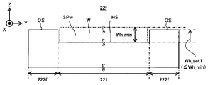
- the stage 22 includes a holding member 221 and an outer peripheral member 222 as shown in FIGS. 4A to 4C.
- the holding member 221 is a flat plate-like (or other arbitrary shape) member extending along the XY plane.
- the holding member 221 includes a holding surface HS that can face the beam irradiation apparatus 1.
- the holding surface HS is a surface facing the + Z side (that is, upward).
- the size of the holding surface HS in the direction along the XY plane is larger than the size of the sample W in the direction along the XY plane, but may be the same.
- the holding surface HS since the sample W has a circular shape in plan view, the holding surface HS is circular in plan view.
- the holding surface HS may be rectangular in plan view.
- the diameter of the holding surface HS is larger than the diameter of the sample W.
- the holding surface HS is a surface that holds the sample W. That is, the holding member 221 holds the sample W with the holding surface HS.
- the holding member 221 is a back surface of the sample W (that is, a surface opposite to the front surface WSu through an exhaust port formed in the holding surface HS, and is from FIG. 4A to FIG. 4C.
- the sample W may be held by vacuum suction on the ⁇ Z side (that is, the surface facing downward).
- the holding member 221 may include a vacuum chuck.
- the holding member 221 may hold the sample W by electrostatically adsorbing the sample W arranged on the holding surface HS via an electrode arranged on the holding member 221.
- the holding member 221 may include an electrostatic chuck.
- the outer peripheral member 222 is disposed around the holding member 221 in the XY plane.
- the outer peripheral member 222 is disposed so as to surround the holding member 221 in the XY plane.
- the sample W has a circular shape in plan view, and therefore the inner contour of the outer peripheral member 222 may be circular.
- the outer peripheral member 222 is integrated with the holding member 221, but may be a member separate from the holding member 221.
- the outer peripheral member 222 is a member formed so as to protrude above the holding member 221 (that is, on the + Z side).
- the outer peripheral member 222 is a member that protrudes upward (that is, + Z side) from the holding surface HS of the holding member 221 substantially.
- the upper surface of the outer peripheral member 222 (specifically, the surface facing the same side as the holding surface HS and in the example shown in FIGS. 4A to 4C, the surface on the + Z side) OS is retained.
- the member 221 is positioned above the holding surface HS.
- the upper surface OS of the outer peripheral member 222 is positioned above the holding surface HS of the holding member 221 by the thickness Wh of the sample W.
- the upper surface OS of the outer peripheral member 222 is positioned at the same height as the surface WSu of the sample W held by the holding member 221.
- the upper surface OS of the outer peripheral member 222 is located in the same plane as the surface WSu of the sample W held by the holding member 221.
- the stage 22 is formed with a recessed accommodation space SPw surrounded by the holding member 221 and the outer peripheral member 222.
- the sample W is stored in the storage space SPw and is held by the holding member 221 in a state where the surface WSu is at the same height as the upper surface OS of the outer peripheral member 222.
- the accommodation space SPw may be circular in plan view.
- the outer peripheral member 222 includes a retracting member 223 adjacent to the holding member 221 in one direction along the XY plane as a part of the outer peripheral member 222.
- the retracting member 223 corresponding to a part of the outer peripheral member 222 is also a separate member from the holding member 221. Also good. Even if the outer peripheral member 222 is the same member as the holding member 221, the retracting member 223 may be a separate member from the holding member 221.
- the retracting member 223 extends in a direction away from the holding member 221 in the XY plane.
- the size of the retracting member 223 (specifically, the size in the direction away from the holding member 221) is larger than the size of the portion adjacent to the holding member 221 in the other direction different from the one direction of the outer peripheral member 222. Also good. That is, in the XY plane, the outer circumferential member 222 has a portion positioned in one direction as viewed from the holding member 221 (that is, the retracting member 223) in another direction different from the one direction as viewed from the holding member 221. You may have the structure which spreads outside relatively much rather than the part located (that is, it spreads away from the holding member 221). In the example shown in FIGS.
- the outer peripheral member 222 is adjacent to the holding member 221 along the Y-axis direction (particularly, adjacent to the holding member 221 on the ⁇ Y side of the holding member 221).
- the size of the retracting member 223 along the Y axis may be larger than the size along the Y axis of the portion of the outer peripheral member 222 adjacent to the holding member 221 on the + Y side, and the outer member 222 The size may be larger than the size along the X axis of the portion adjacent to the holding member 221 on the + X side or the ⁇ X side.
- the upper surface ES of the retracting member 223 corresponds to a part of the upper surface OS of the outer peripheral member 222. Therefore, the upper surface ES of the retracting member 223 is also positioned at the same height as the surface WSu of the sample W held by the holding member 221, similarly to the upper surface OS of the outer peripheral member 222.
- the technical reason why the evacuation member 223 is formed will be described later in detail (see FIG. 5A and subsequent figures).
- a mark for associating the position of the electron beam EB by the beam irradiation device 1 with the position of the stage 22 (position in the XYZ directions) may be provided on a part of the upper surface ES of the retracting member 223. Note that at least one of the upper surface OS of the outer peripheral surface and the upper surface ES of the retracting member 223 may be referred to as an external surface.
- the stage 22 holds the sample W under the control of the control device 4 and follows at least one of the X axis direction, the Y axis direction, the Z axis direction, the ⁇ X direction, the ⁇ Y direction, and the ⁇ Z direction. Can be moved.
- the stage apparatus 2 includes a stage drive system 23.
- the stage drive system 23 moves the stage 22 using, for example, an arbitrary motor (for example, a linear motor).
- the stage apparatus 2 includes a position measuring device 24 that measures the position of the stage 22.
- the position measuring device 24 includes, for example, at least one of an encoder and a laser interferometer.
- the relative position between the sample W and the beam irradiation apparatus 1 in the direction along the XY plane changes. For this reason, when the stage 22 moves along the XY plane, the relative position between the sample W in the direction along the XY plane and the irradiation region of the electron beam EB on the surface WSu of the sample W changes. That is, when the stage 22 moves along the XY plane, the irradiation region of the electron beam EB moves relative to the surface WSu of the sample W in the direction along the XY plane (that is, the direction along the surface WSu of the sample W). To do.
- the relative positions of the sample W, the beam passage space SPb3, and the vacuum region VSP in the direction along the XY plane change. That is, when the stage 22 moves along the XY plane, the beam passing space SPb3 and the vacuum region VSP with respect to the surface WSu of the sample W in the direction along the XY plane (that is, the direction along the surface WSu of the sample W). Move.
- the control device 4 controls the stage drive system 23 so that the electron beam EB is irradiated to a desired position on the surface WSu of the sample W and the beam passage space SPb3 is set (that is, the vacuum region VSP is formed).
- the stage 22 may be moved along the XY plane.
- the control device 4 controls the stage drive system 23 to move the stage 22 along the XY plane so that the vacuum region VSP is formed in the first portion of the surface WSu of the sample W. .
- the beam irradiation apparatus 1 irradiates the first portion of the surface WSu of the sample W with the electron beam EB, The state of the first part is measured.
- the stage drive system 23 does not have to move the stage 22 along the XY plane.
- the control device 4 controls the stage drive system 23 so that the vacuum region VSP is formed in the second part of the surface WSu of the sample W, and moves the stage 22 to the XY plane. Move along. After the stage 22 moves so that the vacuum region VSP is formed in the second part of the surface WSu of the sample W, the beam irradiation apparatus 1 irradiates the second part of the surface WSu of the sample W with the electron beam EB, The state of the second part is measured.
- the stage driving system 23 may not move the stage 22 along the XY plane during the period in which the beam irradiation apparatus 1 irradiates the second portion of the surface WSu of the sample W with the electron beam EB. Thereafter, the state of the surface WSu of the sample W is measured by repeating the same operation.
- the relative position between the sample W and the beam irradiation apparatus 1 in the direction along the Z axis changes.
- the control device 4 moves the stage 22 along the Z axis by controlling the stage drive system 23 so that the focus position of the electron beam EB is set on the surface WSu of the sample W (or in the vicinity of the surface WSu). You may let them.
- the focus position of the electron beam EB may be a focal position corresponding to the imaging position of the beam optical system 11 or a position in the Z-axis direction where the blur of the electron beam EB is minimized.
- the stage drive system 23 may move the stage 22 under the control of the control device 4 so that the interval D becomes the desired interval D_target in cooperation with the interval adjustment system 14 described later.
- the control device 4 is based on the measurement result of the position measurement device 24 (further, the measurement result of the position measurement device 15 that measures the position of the beam irradiation device 1 described later (in particular, the position of the vacuum forming member 121)).
- the actual interval D is specified, and at least one of the stage drive system 23 and the interval adjustment system 14 is controlled so that the specified interval D becomes the desired interval D_target.
- the position measurement devices 15 and 24 can also function as a detection device that detects the interval D.
- the control device 4 replaces / in addition to the actual distance D, and in addition to the beam irradiation device 1 and the reference surface (for example, the surface of the reference plate).
- the stage is set so that the distance from the beam irradiation device 1 to the sample W becomes the target distance. At least one of the drive system 23 and the interval adjustment system 14 may be controlled.
- the support frame 3 supports the beam irradiation device 1.
- the support frame 3 includes support legs 31 and support members 32.
- the support leg 31 is disposed on the support surface SF. Between the support leg 31 and the support surface SF, an anti-vibration device (not shown) for preventing or reducing the transmission of the vibration of the support surface SF to the support leg 31 may be installed.
- the support leg 31 is a member that extends upward from the support surface SF, for example.
- the support leg 31 supports the support member 32.
- the support member 32 is an annular plate member having an opening 321 formed in the center in plan view. On the upper surface of the support member 32, it extends outward from the outer surface of the beam irradiation apparatus 1 (in the example shown in FIGS.
- the support frame 3 can support the beam irradiation device 1 so as to lift it from the upper surface of the support member 32.
- the support frame 3 may support the beam irradiation device 1 by another support method different from the support method shown in FIG. 1 as long as the beam irradiation device 1 can be supported.
- the support frame 3 may support the beam irradiation device 1 so as to be suspended from the lower surface of the support member 32.
- the vibration isolator (not shown) for preventing or reducing the transmission of the vibration of the support surface SF to the support member 32 may be provided.
- the interval adjusting system 14 moves the beam irradiation device 1 at least along the Z axis, thereby causing the interval D between the emission surface 121LS of the vacuum forming member 121 and the surface WSu of the sample W or the emission of the vacuum forming member 121.
- the distance in the Z-axis direction from the surface 121LS to the surface WSu of the sample W is adjusted.
- the interval adjusting system 14 may move the beam irradiation apparatus 1 along the Z-axis direction so that the interval D becomes the desired interval D_target.
- an interval adjustment system 14 for example, a drive system that moves the beam irradiation apparatus 1 using a driving force of a motor, a drive system that moves the beam irradiation apparatus 1 using a force generated by the piezoelectric effect of a piezoelectric element, A drive system that moves the beam irradiation device 1 using Coulomb force (for example, electrostatic force generated between at least two electrodes) and Lorentz force (for example, electromagnetic force generated between the coil and the magnetic pole) are used.
- Coulomb force for example, electrostatic force generated between at least two electrodes
- Lorentz force for example, electromagnetic force generated between the coil and the magnetic pole
- a distance adjusting member such as a shim is provided between the support member 32 and the flange member 13 instead of the distance adjusting system 14. May be arranged.
- the gap adjusting member such as a shim may not be disposed between the support member 32 and the flange member 13.
- the beam irradiation apparatus 1 may be movable along the XY directions.
- the scanning electron microscope SEM includes a position measuring device 15. Yes.
- the position measuring device 15 includes, for example, at least one of an encoder and a laser interferometer. Note that the position measuring device 15 may measure the position of the beam irradiation apparatus 1 in the XY direction and the attitude in the ⁇ X direction and the ⁇ Y direction. Further, a measurement device that measures the position of the beam irradiation device 1 in the XY direction, the orientation in the ⁇ X direction, and the ⁇ Y direction may be provided separately from the position measuring device 15.
- Control device 4 controls the operation of the scanning electron microscope SEM.
- the control device 4 controls the beam irradiation device 1 so as to irradiate the sample W with the electron beam EB.
- the control device 4 controls the pump system 5 (particularly, the vacuum pumps 51 and 52) so that the beam passage spaces SPb1 to SPb3 are in a vacuum space.
- the control device 4 controls the stage drive system 23 so that the electron beam EB is irradiated to a desired position on the surface WSu of the sample W.
- the control device 4 controls the interval adjustment system 14 so that the interval D between the emission surface 121LS of the vacuum forming member 121 and the surface WSu of the sample W becomes the desired interval D_target.
- the control device 4 may include at least one of an arithmetic device such as a CPU (Central Processing Unit) and a storage device such as a memory.
- the retracting member 223 is mainly used for maintaining the vacuum region VSP formed by the beam irradiation apparatus 1 (in other words, continuing to form it). For this reason, the retracting member 223 may have a size such that a vacuum region VSP can be formed between the beam irradiation device 1 and the retracting member 223.
- the upper surface ES of the retracting member 223 may have a size larger than the size of the vacuum region VSP in the XY direction.
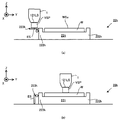
- FIG. 5 (a) to FIG. 5 (b), FIG. 6 (a) to FIG. 6 (b), and FIG. A method for maintaining the vacuum region VSP formed by the beam irradiation apparatus 1 using the evacuation member 223 will be described with reference to FIG.
- the upper surface ES of the retracting member 223 is positioned at the same height as the surface WSu of the sample W held by the holding member 221. Therefore, when the stage 22 moves so that the beam irradiation apparatus 1 is detached from the sample W to the retracting member 223 (that is, the beam irradiation apparatus 1 that has been opposed to the sample W is opposed to the retracting member 223). Even in this case, the vacuum region VSP formed between the beam irradiation apparatus 1 and the sample W is similarly maintained between the beam irradiation apparatus 1 and the retracting member 223.
- the retracting member 223 can be used for maintaining the vacuum region VSP formed by the beam irradiation apparatus 1. That is, the retracting member 223 can be used to maintain the vacuum region VSP when the beam irradiation apparatus 1 moves between the sample W and the retracting member 223 as the stage 22 moves.
- the removal of the beam irradiation apparatus 1 from the sample W to the retracting member 223 changes from a state in which the irradiation position of the electron beam EB by the beam irradiation apparatus 1 is on the sample W to a state on the upper surface ES of the retracting member 223.
- the fact that the beam irradiation device 1 is disengaged from the retracting member 223 to the sample W means that the irradiation position of the electron beam EB by the beam irradiation device 1 is on the sample W from the state where the irradiation position is on the upper surface ES of the retracting member 223. It may be referred to as changing to a certain state.
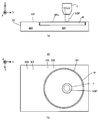
- the beam irradiation device 1 forms a vacuum region VSP between the sample W and the beam irradiation device 1 as shown in FIGS. 5 (a) and 5 (b).
- a situation is assumed in which the beam irradiation apparatus 1 faces the sample W.
- the beam irradiation apparatus 1 moves along the Y-axis direction and toward the ⁇ Y side with respect to the stage 22. Move relatively toward.
- the vacuum region VSP formed by the beam irradiation apparatus 1 also moves relative to the stage 22 along the Y-axis direction and toward the ⁇ Y side on the surface WSu of the sample W.
- the beam irradiation apparatus 1 moves the sample W through the state shown in FIGS. 6A and 6B, as shown in FIGS. 7A and 7B.
- the state of the beam irradiation apparatus 1 is switched from the non-reserved state facing the sample W to the retracted state facing the retracting member 223. That is, the state of the beam irradiation apparatus 1 is switched from the non-reserved state in which the vacuum region VSP can be formed with the sample W to the retracted state in which the vacuum region VSP can be formed with the retracting member 223.
- the state of the beam irradiation apparatus 1 is temporarily changed to the sample W and It will be in the intermediate state which opposes both of the retracting members 223. That is, the state of the beam irradiation apparatus 1 temporarily becomes an intermediate state in which the vacuum region VSP that faces the boundary between the sample W and the retracting member 223 is formed.
- the distance D between the beam irradiation apparatus 1 in the intermediate state and the sample W is relatively There is a possibility of a big shift. For this reason, while the interval D is an interval at which the vacuum region VSP can be appropriately formed, the interval D ′ may not be an interval at which the vacuum region VSP can be appropriately formed.
- the vacuum region formed by the beam irradiation device 1 when the state of the beam irradiation device 1 that has appropriately formed the vacuum region VSP with the sample W is switched from the non-reserved state to the intermediate state.
- the VSP can be destroyed (in other words, it can collapse or disappear). That is, when the state of the beam irradiation apparatus 1 is switched from the non-reserved state to the intermediate state, the beam irradiation apparatus 1 may not be able to form the vacuum region VSP that faces the boundary between the sample W and the retracting member 223. There is sex.
- the beam irradiation apparatus 1 switches from the non-reserved state to the retracted state, there is a possibility that the beam irradiation apparatus 1 cannot continue to form (that is, maintain) the vacuum region VSP properly. .
- the interval D ′ between the beam irradiation apparatus 1 and the retracting member 223 becomes the desired interval D_target.
- the vacuum region VSP is formed again after adjusting the distance D ′.
- the upper surface ES of the retracting member 223 is located at the same height as the surface WSu of the sample W. For this reason, there is a possibility that the distance D between the beam irradiation apparatus 1 in the intermediate state and the sample W and the distance D ′ between the beam irradiation apparatus 1 in the intermediate state and the retracting member 223 are relatively large. Is relatively small. Typically, the distance D coincides with the distance D '. Therefore, when the interval D is an interval at which the vacuum region VSP can be appropriately formed, the interval D ′ is also an interval at which the vacuum region VSP can be appropriately formed.
- the vacuum region formed by the beam irradiation device 1 is relatively small. That is, even when the state of the beam irradiation apparatus 1 is switched from the non-reserved state to the intermediate state, the beam irradiation apparatus 1 can appropriately form the vacuum region VSP that faces the boundary between the sample W and the retracting member 223. it can.
- the beam irradiation apparatus 1 can continue to form (that is, maintain) the vacuum region VSP appropriately. For this reason, even if the state of the beam irradiation apparatus 1 is switched from the non-reserved state to the retracted state through the intermediate state, the beam irradiation apparatus 1 can continue to form the vacuum region VSP appropriately. That is, the scanning electron microscope SEM can switch the state of the beam irradiation apparatus 1 from the non-evacuation state to the withdrawal state while the vacuum region VSP is formed.
- the beam irradiation apparatus 1 can continue to form the vacuum region VSP appropriately. That is, the scanning electron microscope SEM can switch the state of the beam irradiation apparatus 1 from the retracted state to the non-retracted state while forming the vacuum region VSP.
- At this time, at least one of the interval adjustment system 14 and the stage drive system 23 is in the non-retreat state before and after the state of the beam irradiation apparatus 1 is switched from the non-retreat state to the retreat state or from the retreat state to the non-retreat state.
- the deviation amount between the distance D between the beam irradiation apparatus 1 and the sample W and the distance D ′ between the beam irradiation apparatus 1 in the retracted state and the retracting member 223 is less than or equal to the allowable lower limit value.
- the relative position between the stage 22 and the beam irradiation apparatus 1 in the Z-axis direction may be adjusted.
- At least one of the interval adjustment system 14 and the stage drive system 23 is provided between the beam irradiation apparatus 1 and the sample W in the non-reserved state when the state of the beam irradiation apparatus 1 is switched from the non-reserved state to the retracted state.
- the distance D is the desired first distance D_desire1 in which the vacuum region VSP can be appropriately formed between the beam irradiation apparatus 1 and the sample W
- the beam irradiation apparatus 1 and the retreat member 223 in the retreat state are set.
- the relative position between the stage 22 and the beam irradiation apparatus 1 may be adjusted.
- the difference between the first interval D_desire1 and the second interval D_desire2 is less than or equal to the allowable lower limit value.
- the first interval D_desire1 and the second interval D_desire2 may be the same.
- at least one of the first interval D_desire1 and the second interval D_desire2 may be the same as the above-described desired interval D_target.
- the stage drive system 23 may adjust the relative position between the stage 22 and the beam irradiation apparatus 1 in the direction along the XY plane, and the state of the beam irradiation apparatus 1 may be switched from the non-reserved state to the retracted state.
- at least one of the interval adjustment system 14 and the stage drive system 23 is configured such that when the state of the beam irradiation apparatus 1 is switched from the retracted state to the non-retracted state, the beam irradiation apparatus 1 and the retracting member 223 in the retracted state. Transition from a state in which the distance D ′ between the first and second beams D_desire2 to the state W is a first distance D_desire1 is performed.
- the relative position between the stage 22 and the beam irradiation apparatus 1 in the Z-axis direction may be adjusted. Thereafter, the stage drive system 23 may adjust the relative position between the stage 22 and the beam irradiation apparatus 1 in the direction along the XY plane to switch the state of the beam irradiation apparatus 1 from the retracted state to the non-retracted state. As a result, the beam irradiation apparatus 1 can continue to form the vacuum region VSP more appropriately before and after the state of the beam irradiation apparatus 1 is switched from the non-reserved state to the retracted state or from the retracted state to the non-retracted state. .
- the upper surface ES of the retracting member 223 is positioned at the same height as the surface WSu of the sample W. For this reason, the relative position of the beam irradiation apparatus 1 with respect to the stage 22 in the Z-axis direction does not change before and after the state of the beam irradiation apparatus 1 is switched from the non-reserved state to the retracted state or from the retracted state to the non-retracted state ( In other words, if maintained, the distance D and the distance D ′ coincide.
- At least one of the interval adjustment system 14 and the stage drive system 23 is the stage in the Z-axis direction before and after the state of the beam irradiation apparatus 1 is switched from the non-reserved state to the retracted state or from the retracted state to the non-retracted state. You may adjust so that the relative position of 22 and the beam irradiation apparatus 1 may be maintained.
- At least one of the interval adjustment system 14 and the stage drive system 23 is the interval D and the interval D ′ before and after the state of the beam irradiation apparatus 1 is switched from the non-reserved state to the retracted state or from the retracted state to the non-retracted state.
- the relative position between the stage 22 and the beam irradiation apparatus 1 in the Z-axis direction may be adjusted so that is different.
- At least one of the interval adjustment system 14 and the stage drive system 23 has the interval D set to the first interval D_desire1 that can appropriately form the vacuum region VSP between the beam irradiation apparatus 1 and the sample W, and the interval D
- the stage 22 in the Z-axis direction is such that D ′ can appropriately form the vacuum region VSP between the beam irradiation device 1 and the retracting member 223 and is a second interval D_desire2 different from the first interval D_desire1.
- the relative position of the beam irradiation apparatus 1 may be adjusted.
- the beam irradiation device 1 before and after the state of the beam irradiation device 1 is switched from the non-reserved state to the retracted state or from the retracted state to the non-retracted state.
- the vacuum region VSP can be continuously formed more appropriately.
- at least one of the interval adjustment system 14 and the stage drive system 23 has an appropriate vacuum region VSP before and after the state of the beam irradiation apparatus 1 is switched from the non-reserved state to the retracted state or from the retracted state to the non-retracted state. So that the state of the beam irradiation device 1 is changed (that is, the movement of the stage 22 along the XY plane) or in succession, the stage 22 and the beam irradiation device 1 in the Z-axis direction are Adjust the relative position.
- the loading / unloading of the sample W is performed, for example, after the measurement of the state of the sample W held by the stage 22 is completed.
- the beam irradiation apparatus 1 needs to irradiate the sample W with the electron beam EB. For this reason, before the sample W is carried in and out (that is, at least during a period during which the stage 22 holds the sample W), as shown in FIG. A vacuum region VSP is formed with the sample W while facing the W. That is, the beam irradiation apparatus 1 is in a non-evacuation state.
- the stage drive system 23 moves the stage 22 along the XY plane, and changes the state of the beam irradiation apparatus 1 to the non-evacuation state. Switch from to the save state.
- at least one of the interval adjustment system 14 and the stage drive system 23 adjusts the relative position of the beam irradiation apparatus 1 with respect to the stage 22 in the Z-axis direction so that the vacuum region VSP is appropriately maintained. May be.
- the vacuum region VSP is maintained before and after the state of the beam irradiation apparatus 1 is switched from the non-reserved state to the retracted state. That is, the beam irradiation apparatus 1 moves with respect to the stage 22 while the vacuum region VSP is continuously formed between the sample W and the retracting member 223.
- the sample W held by the stage 22 is carried in / out. Specifically, as shown in FIG. 8C, the sample W held by the stage 22 (that is, the sample W for which the state measuring operation has been completed) is unloaded from the stage 22 (that is, carried out). ). Thereafter, as shown in FIG. 8D, a new sample W (that is, a sample W for which a state measuring operation is newly performed) is loaded onto the stage 22 (that is, loaded). ) During the period in which the sample W held by the stage 22 is carried in and out, as shown in FIGS. 8C and 8D, the state of the beam irradiation apparatus 1 is maintained in the retracted state.
- the beam irradiation apparatus 1 is in a vacuum region between the retracting member 223 as shown in FIGS. 8C and 8D. Continue to form the VSP.
- the stage drive system 23 moves the stage 22 along the XY plane, and changes the state of the beam irradiation apparatus 1 from the retracted state to the non-retracted state. Switch. Also at this time, as described above, at least one of the interval adjustment system 14 and the stage drive system 23 adjusts the relative position of the beam irradiation apparatus 1 with respect to the stage 22 in the Z-axis direction so that the vacuum region VSP is appropriately maintained. May be. As a result, the vacuum region VSP is maintained before and after the state of the beam irradiation apparatus 1 is switched from the retracted state to the non-retracted state. That is, the beam irradiation apparatus 1 moves with respect to the stage 22 while the vacuum region VSP is continuously formed between the sample W and the retracting member 223.
- the scanning electron microscope SEM irradiates the new sample W with the electron beam EB and measures the state of the new sample W. That is, the beam irradiation apparatus 1 irradiates the sample W with the electron beam EB through the vacuum region VSP formed with the sample W.
- the scanning electron microscope SEM can carry in and out the sample W held by the stage 22 while maintaining the vacuum region VSP. For this reason, the scanning electron microscope SEM does not need to newly form the vacuum region VSP every time the sample W is carried in and out. That is, the scanning electron microscope SEM returns the beam passage spaces SPb1 to SPb3 to the atmospheric pressure space before loading and unloading the sample W, and evacuates the beam passage spaces SPb1 to SPb3 again after loading and unloading the sample W. It does not have to be in space. As a result, the scanning electron microscope SEM requires more time for forming the vacuum region VSP than the scanning electron microscope of the comparative example in which the vacuum region VSP needs to be newly formed each time the sample W is carried in and out. Thus, the time required for measuring the sample W can be shortened. That is, the throughput of the scanning electron microscope SEM is improved.
- the operation of newly forming the vacuum region VSP is performed, for example, when measurement of the state of the sample W held by the stage 22 is newly started. Specifically, the operation of newly forming the vacuum region VSP is performed, for example, before the irradiation of the electron beam EB is started in order to measure the state of the sample W.
- the beam irradiation apparatus 1 newly forms a vacuum region VSP in the retracted state.
- the beam irradiation apparatus 1 newly forms a vacuum region VSP in a state of facing the retreat member 223.
- the beam irradiation apparatus 1 newly forms a vacuum region VSP between the retracting member 223.
- the beam irradiation apparatus 1 does not need to newly form the vacuum region VSP in the non-reserved state.
- the beam irradiation apparatus 1 does not have to newly form the vacuum region VSP in a state of facing the sample W.
- the beam irradiation apparatus 1 does not need to form a new vacuum region VSP between the sample W and the sample. Therefore, as shown in FIG.
- the stage drive system 23 when the beam irradiation apparatus 1 is in the non-reserved state before the beam irradiation apparatus 1 starts to form the vacuum region VSP, the stage drive system 23 is placed on the XY plane. The stage 22 is moved along, and the state of the beam irradiation apparatus 1 is switched from the non-evacuation state to the withdrawal state as shown in FIG. 9B. On the other hand, if the beam irradiation apparatus 1 is already in the retracted state before the beam irradiation apparatus 1 starts to form the vacuum region VSP, the stage drive system 23 may not move the stage 22.
- the beam irradiation apparatus 1 newly forms a vacuum region VSP. Specifically, using at least one of the interval adjustment system 14 and the stage drive system 23, the interval D between the emission surface 121LS of the beam irradiation apparatus 1 and the upper surface ES of the retracting member 223 is set as a desired interval D_target. Thereafter, the vacuum pump 51 exhausts and depressurizes the beam passage spaces SPb1 to SPb3. Further, the vacuum pump 52 exhausts and decompresses the space around the beam passage space SPb3. As a result, the beam irradiation apparatus 1 (particularly, the differential exhaust system 12) can form a vacuum region VSP between the retracting member 223 by differential exhaust.
- the stage drive system 23 moves the stage 22 along the XY plane, and changes the state of the beam irradiation apparatus 1 from the retracted state as shown in FIG. Switch to non-evacuation state.
- at least one of the interval adjustment system 14 and the stage drive system 23 adjusts the relative position of the beam irradiation apparatus 1 with respect to the stage 22 in the Z-axis direction so that the vacuum region VSP is appropriately maintained. May be.
- the vacuum region VSP is maintained before and after the state of the beam irradiation apparatus 1 is switched from the retracted state to the non-retracted state.
- the beam irradiation apparatus 1 moves with respect to the stage 22 while the vacuum region VSP is continuously formed between the sample W and the retracting member 223. For this reason, the vacuum region VSP formed so as to face the retracting member 223 moves relative to the stage 22 so as to move from the retracting member 223 to the sample W.
- the scanning electron microscope SEM irradiates the sample W with the electron beam EB and measures the state of the sample W. That is, the beam irradiation apparatus 1 irradiates the sample W with the electron beam EB through the vacuum region VSP formed with the sample W.
- the scanning electron microscope SEM newly forms the vacuum region VSP between the electron beam irradiation apparatus 1 and the retracting member 223, and from the retracting member 223 while maintaining the newly formed vacuum region VSP. It can be moved to the sample W. That is, when the scanning electron microscope SEM newly forms the vacuum region VSP to start measuring the state of the sample W, the space between the electron beam irradiation apparatus 1 and the retracting member 223 is changed to the vacuum region VSP. Can be set as a space for forming a new pattern. For this reason, the scanning electron microscope SEM does not need to newly form the vacuum region VSP between the electron beam irradiation apparatus 1 and the sample W.
- the scanning electron microscope SEM does not need to set the space between the electron beam irradiation apparatus 1 and the sample W as a space for newly forming the vacuum region VSP. For this reason, the scanning electron microscope SEM can newly form the vacuum region VSP while suppressing the influence of the new formation of the vacuum region VSP on the sample W. For example, when a vacuum region VSP is newly formed on a certain object, the pressure in the space facing the object decreases rapidly. For this reason, there is a possibility that the temperature of the object (particularly, the temperature of the part facing the space where the pressure decreases in the object) may fluctuate. Variations in the temperature of the object can lead to thermal deformation of the object. The thermal deformation of the object may deteriorate the measurement accuracy of the object state.
- a vacuum region VSP is newly formed between the electron beam irradiation apparatus 1 and the sample W, the sample W may be thermally deformed and the measurement accuracy of the state of the sample W may deteriorate.
- a vacuum region VSP is newly formed between the electron beam irradiation apparatus 1 and the retracting member 223. For this reason, the thermal deformation of the sample W resulting from the new formation of the vacuum region VSP is suppressed. For this reason, the scanning electron microscope SEM can measure the state of the sample W with relatively high accuracy.
- the beam irradiation apparatus 1 may newly form the vacuum region VSP in the retracted state.
- the beam irradiation apparatus 1 may newly form a vacuum region VSP in a state of facing the sample W.
- the beam irradiation apparatus 1 may newly form a vacuum region VSP with the sample W.
- FIG. 10 is a cross-sectional view showing the structure of the stage 22a of the first modification.
- the stage 22a is different from the stage 22 described above in that at least one mark area MA is formed on at least a part of the upper surface ES of the retracting member 223.
- the other structure of the stage 22a may be the same as the stage 22.
- At least one mark M is formed in the mark area MA.
- the mark M is a lattice mark formed such that longitudinal line marks MX extending along the X-axis direction are arranged at a desired pitch ⁇ X along the Y-axis direction.
- M1 may be included.
- the mark M is a lattice mark formed such that longitudinal line marks MY extending along the Y-axis direction are arranged at a desired pitch ⁇ Y along the X-axis direction.
- M2 may be included.
- FIG. 11A the mark M is a lattice mark formed such that longitudinal line marks MX extending along the X-axis direction are arranged at a desired pitch ⁇ X along the Y-axis direction.
- the mark M is formed by a longitudinal line mark ML extending along a first direction intersecting both the X-axis direction and the Y-axis direction. It may include lattice marks M3 formed so as to be arranged at a desired pitch ⁇ L along two directions. Of course, the mark M may include a mark different from the marks shown in FIGS.
- the mark M is used to set the operation state of the scanning electron microscope SEMa (in other words, calibrate, calibrate, or adjust). Therefore, the retracting member 223 may be referred to as a reference plate.
- the beam irradiation apparatus 1 irradiates the mark M with the electron beam EB through the vacuum region VSP. Further, the beam irradiation apparatus 1 uses the electron detector 116 to detect electrons (for example, at least one of reflected electrons and scattered electrons) generated by irradiation of the mark M with the electron beam EB.
- the control device 4 specifies the characteristics of the scanning electron microscope SEMa based on the detection result of the electron detector 116.
- the control device 4 sets the operating state of the scanning electron microscope SEMa based on the specified characteristics of the scanning electron microscope SEMa. For example, the control device 4 specifies and specifies the characteristics (for example, at least one of intensity, spot diameter, and focus position) of the electron beam EB irradiated by the beam irradiation device 1 based on the detection result of the electron detector 116.
- the operating state of the beam irradiation apparatus 1 may be set so as to irradiate the electron beam EB having an appropriate characteristic based on the state of the electron beam EB.
- control device 4 specifies the relative position between the beam irradiation device 1 and the stage 22a based on the detection result of the electron detector 116, and the position between the beam irradiation device 1 and the stage 22a based on the specified relative position. You may combine.
- control device 4 identifies and identifies the characteristics (for example, at least one of the degree of vacuum and the formation position) of the vacuum region VSP formed by the beam irradiation device 1 based on the detection result of the electron detector 116.
- an apparatus related to the formation of the vacuum region VSP so as to form a vacuum region VSP having appropriate characteristics for example, the beam irradiation device 1, the interval adjustment system 14, the stage drive system 23, and the pump
- the operating state of at least one of the systems 5 may be set.
- the scanning electron microscope SEMa uses the beam irradiation apparatus 1 in the retracted state to apply electrons to the mark M. Irradiate beam EB. That is, the beam irradiation apparatus 1 irradiates the mark M with the electron beam EB in the retracted state. The beam irradiation apparatus 1 irradiates the mark M with the electron beam EB in a state where the beam irradiation apparatus 1 faces the retracting member 223.
- the beam irradiation apparatus 1 irradiates the mark M with the electron beam EB in a state where the vacuum region VSP is formed between the beam irradiation device 1 and the retracting member 223. Therefore, as shown in FIG. 12A, when the beam irradiation apparatus 1 is in the non-reserved state before the setting of the operation state of the scanning electron microscope SEMa is started, the stage drive system 23 is connected to the XY plane. As shown in FIG. 12B, the state of the beam irradiation apparatus 1 is switched from the non-evacuation state to the withdrawal state.
- the beam irradiation apparatus 1 has already formed the vacuum region VSP with the sample W, as described above, at least one of the interval adjustment system 14 and the stage drive system 23 has the vacuum region VSP.
- the vacuum region VSP is maintained before and after the state of the beam irradiation apparatus 1 is switched from the non-reserved state to the retracted state. That is, the beam irradiation apparatus 1 moves with respect to the stage 22a while continuing to form the vacuum region VSP between at least one of the sample W and the retracting member 223.
- the stage drive system 23 may not move the stage 22a.
- the beam irradiation device 1 applies the electron beam EB to the mark region MA. Irradiate. That is, the beam irradiation apparatus 1 irradiates the mark M formed in the mark area MA with the electron beam EB. At this time, the beam irradiation apparatus 1 irradiates the mark M with the electron beam EB through the vacuum region VSP facing the mark region MA. Thereafter, the control device 4 sets the operating state of the scanning electron microscope SEMa based on the detection result of the electron detector 116.
- the state of the beam irradiation apparatus 1 is maintained in the retracted state.
- the beam irradiation apparatus 1 continues to form the vacuum region VSP between the retracting member 223 (particularly, between the mark region MA).
- the beam irradiation apparatus 1 does not necessarily have to face the retracting member 223 (particularly, the mark area MA).
- the control device 4 uses the scanning electron based on the detection result of the electron detector 116.
- the beam irradiation device 1 does not have to face the retreat member 223.
- the state of the beam irradiation apparatus 1 is maintained in the retracted state, while the beam irradiation is performed in at least a part of the period other than the beam irradiation period of the setting period.
- the state of the device 1 may be a non-evacuation state.
- the stage drive system 23 moves the stage 22a along the XY plane. Then, as shown in FIG. 12 (d), the state of the beam irradiation apparatus 1 is switched from the retracted state to the non-retracted state. At this time, as described above, at least one of the interval adjustment system 14 and the stage drive system 23 adjusts the relative position of the beam irradiation apparatus 1 with respect to the stage 22a in the Z-axis direction so that the vacuum region VSP is appropriately maintained. May be.
- the vacuum region VSP is maintained before and after the state of the beam irradiation apparatus 1 is switched from the retracted state to the non-retracted state. That is, the beam irradiation apparatus 1 moves with respect to the stage 22a while continuing to form the vacuum region VSP between at least one of the sample W and the retracting member 223. For this reason, the vacuum region VSP formed so as to face the retracting member 223 moves relative to the stage 22a so as to move from the retracting member 223 to the sample W.
- the scanning electron microscope SEMa measures the state of the sample W by irradiating the sample W with the electron beam EB. That is, the beam irradiation apparatus 1 irradiates the sample W with the electron beam EB through the vacuum region VSP formed with the sample W. At this time, since the operation state of the scanning electron microscope SEMa has already been set, the scanning electron microscope SEMa can more appropriately measure the state of the sample W.
- the scanning electron microscope SEMa can set the operating state of the scanning electron microscope SEMa while maintaining the vacuum region VSP. For this reason, the scanning electron microscope SEMa does not need to newly form the vacuum region VSP every time the operating state of the scanning electron microscope SEMa is set. That is, the scanning electron microscope SEMa moves the beam irradiation device 1 to the mark area MA by returning the beam passage spaces SPb1 to SPb3 to the atmospheric pressure space before setting the operating state of the scanning electron microscope SEMa, and then moves the mark Before the region MA is irradiated with the electron beam EB, the beam passing spaces SPb1 to SPb3 need not be exhausted again to form a vacuum space.
- the scanning electron microscope SEMa compares the vacuum region VSP with the scanning electron microscope of the comparative example in which the vacuum region VSP needs to be newly formed each time the operation state of the scanning electron microscope SEMa is set.
- the time required for setting the operating state of the scanning electron microscope SEMa can be shortened by the time required for formation. That is, the throughput of the scanning electron microscope SEMa is improved.
- the mark M may be formed on a member different from the evacuation member 223.
- the mark M may be provided on the upper surface OS of the outer peripheral member 222.
- the upper surface ES of the retracting member 223 may be used as the reference surface of the position measuring device 15.
- FIG. 13A is a cross-sectional view showing the structure of the stage 22b of the second modified example
- FIG. 13B is a plan view showing the structure of the stage 22b of the second modified example.
- the stage 22b differs from the stage 22 in that an exhaust port 2231b is formed on the holding surface HS of the holding member 221.
- the other structure of the stage 22b may be the same as that of the stage 22.
- the exhaust port 2231b is formed near the outer edge of the holding surface HS of the holding member 221.
- the size (eg, diameter) of the holding surface HS is larger than the size (eg, diameter) of the sample W in the direction along the XY plane.
- the holding member 221 holds the sample W, the sample W and the outer peripheral member 222 do not adhere to each other in the vicinity of the outer edge of the holding surface HS. That is, the holding member 221 holds the sample W in a state where a space is secured between the sample W and the outer peripheral member 222 (that is, between the surface WSu of the sample W and the upper surface OS of the outer peripheral member 222).
- the exhaust port 2231b faces at least a part of a space (also referred to as a gap or a gap) SPg between the sample W and the retracting member 223 in the space between the sample W and the outer peripheral member 222. It is formed. The portion of the holding surface HS that faces the space SPg does not actually hold the sample W. For this reason, the exhaust port 2231b is formed in at least a part of the holding surface HS that does not actually hold the sample W (that is, a part facing the space SPg). As described above, since the retracting member 223 is adjacent to the holding member 221 in one direction along the XY plane, the exhaust port 2231b is formed near the outer edge of the holding surface HS in one direction where the retracting member 223 exists. Is done.
- a plurality of exhaust ports 2231b are formed so as to be discretely arranged in a discrete arrangement pattern on the holding surface HS. Specifically, a plurality of exhaust ports 2231b are formed on the holding surface HS so as to be arranged in an arrangement pattern according to the distribution pattern of the space SPg. In the example shown in FIG. 13B, the space SPg between the sample W having a circular shape in a plan view and the retracting member 223 defining the circular accommodation space SPw is distributed in a circumferential shape in the plan view. Therefore, a plurality of exhaust ports 2231b are formed so as to be arranged in a discrete arrangement pattern along the circumference.
- the intervals along the circumference of the plurality of exhaust ports 2231b may be equal intervals or unequal intervals.
- the plurality of exhaust ports 2231b may not be formed.
- a single exhaust port 2231b may be formed.
- the exhaust ports 2231b may be formed so as to be continuously distributed in a continuous distribution pattern on the holding surface HS.
- the exhaust ports 2231b may be formed as exhaust grooves that are continuously distributed on the holding surface HS.
- the exhaust port 2231b may be annular.
- a vacuum pump 53 provided in the pump system 5 is connected to the exhaust port 2231b through a pipe 2232b. However, at least one of the vacuum pumps 51 and 52 included in the pump system 5 may be connected to the exhaust port 2231b via a pipe 2232b. The vacuum pump 53 can reduce the pressure by exhausting the space SPg. The vacuum pump 53 (or at least one of the vacuum pumps 51 and 52) may be referred to as an exhaust device.
- the vacuum pump 53 evacuates the space SPg in at least a part of a period during which the state of the beam irradiation apparatus 1 is switched from the retracted state to the non-retracted state or from the non-retracted state to the retracted state.
- the vacuum pump 53 evacuates the space SPg during at least a part of a period in which the beam irradiation device 1 is in an intermediate state.
- the vacuum pump 53 is a period in which the beam irradiation device 1 forms a vacuum region VSP that faces the boundary between the sample W and the retracting member 223 (that is, faces the space SPg). At least a part of the space SPg is exhausted.
- the vacuum pump 53 exhausts the space SPg in at least a part of a period in which the boundary (that is, the space SPg) between the sample W and the retracting member 223 overlaps at least a part of the vacuum region VSP in the Z-axis direction.
- the vacuum pump 53 evacuates at least a part of the space SPg facing at least a part of the vacuum region VSP, or is not facing at least the vacuum region VSP of the space SPg. It is not necessary to exhaust at least another part of the space that is separated.
- the scanning electron microscope SEM controls a valve (not shown) disposed in the pipe 2232b so as to correspond to each of the plurality of exhaust ports 2231b, and faces at least the vacuum region VSP in the space SPg.
- the exhaust port 2231b that faces at least a part of the space located in the vicinity communicates with the vacuum pump 53, while at least the other part of the space SPg that does not face or separate from the vacuum region VSP.
- the exhaust port 2231 b facing the part may be blocked from the vacuum pump 53. That is, one exhaust port 2231b located in the range where the vacuum region VSP is formed in the direction along the surface WSu of the sample W among the plurality of exhaust ports 2231b exhausts the space SPg, while the plurality of exhaust ports Of the 2231b, another exhaust port 2231b that is not located within the range where the vacuum region VSP is formed in the direction along the surface WSu of the sample W may not exhaust the space SPg. In this case, typically, in the direction along the surface WSu of the sample W, one exhaust port 2231b that exhausts the space SPg is closer to the vacuum region VSP than the other exhaust port 2231b that does not exhaust the space SPg. To position.
- the vacuum region VSP is more appropriately maintained.
- gas may flow into the vacuum region VSP facing the space SPg via the space SPg when the beam irradiation apparatus 1 is in an intermediate state.
- the space SPg for example, the greater the distance between the sample W and the retracting member 223
- the possibility that gas will flow into the vacuum region VSP via the space SPg As a result, the degree of vacuum in the vacuum region VSP may decrease.
- the space SPg since the space SPg is exhausted and depressurized, the possibility that gas flows into the vacuum region VSP via the space SPg becomes relatively small. For this reason, the fall of the vacuum degree of the vacuum area
- the vacuum pump 53 is in the space SPg in a state where the state of the beam irradiation apparatus 1 cannot be switched, typically in at least a part of a period during which the beam irradiation apparatus 1 is in the retracted state or the beam irradiation apparatus 1 is in the non-retracted state. May be exhausted.
- the vacuum pump 53 may exhaust the space SPg during the entire operation period of the scanning electron microscope SEM. Further, the vacuum pump 53 may exhaust the space SPg during the operation period of the scanning electron microscope SEM except for the period during which the sample W is carried in and out.
- the exhaust port 2231b is formed on the holding surface HS of the holding member 221.
- the exhaust port 2231b may be formed at an arbitrary position where the space SPg can be exhausted.
- the exhaust port 2231b may be formed at an arbitrary position facing the space SPg.
- the exhaust port 2231b may be formed on the inner surface (that is, the surface facing the space SPg) of the retracting member 223.
- the exhaust port 2231b is formed so as to face at least a part of the space SPg between the sample W and the retracting member 223 in the space between the sample W and the outer peripheral member 222. Yes.
- the exhaust port 2231 b is at least one of the spaces SPg ′ other than the space SPg between the sample W and the retracting member 223 in the space between the sample W and the outer peripheral member 222. It may be formed so as to face the part.
- the vacuum pump 53 exhausts the space SPg during at least a part of a period different from the period during which the state of the beam irradiation apparatus 1 is switched from the retracted state to the non-retracted state or from the non-retracted state to the retracted state. May be.
- the vacuum pump 53 includes a space (particularly, a space between the sample W and the outer peripheral member 222 in at least a part of a period in which the beam irradiation apparatus 1 forms a vacuum region VSP facing the boundary between the sample W and the outer peripheral member 222. Of the space between the sample W and the outer peripheral member 222, a space portion that overlaps at least a part of the vacuum region VSP in the Z-axis direction) may be exhausted. Further, in this case, the outer peripheral member 222 may not include the retracting member 223. When the outer peripheral member 222 does not include the retracting member 223, the operation using the retracting member 223 described above may not be performed.
- FIG. 17A is a cross-sectional view showing the sample W held on the stage 22 in the third modification
- FIG. 17B is a plan view showing the sample W held on the stage 22 in the third modification.
- the stage 22 has a gap G1 between the sample W and the evacuation member 223 so that the evacuation between the sample W and the outer circumferential member 222 is performed.
- the sample W is held so that the gap G2 between the portions other than the member 223 is different. That is, the stage 22 holds the sample W so that the sample W is distributed with a bias with respect to the holding surface HS, instead of holding the sample W so that the holding surface HS and the sample W are concentric.
- the stage 22 has a gap G1 between the sample W and the retracting member 223 opposite to the retracting member 223 of the sample W and the outer peripheral member 222. The sample W is held so as to be smaller than the gap G2 between the portion located at the position.
- the space between the sample W and the retracting member 223 is compared with the case where the stage 22 holds the sample W so that the holding surface HS and the sample W are concentric.
- the possibility that SPg becomes small is relatively high.
- the space SPg becomes small the possibility that gas flows into the vacuum region VSP via the space SPg becomes small. For this reason, the fall of the vacuum degree of the vacuum area
- the shape of the holding surface HS may be different from that of the sample W.
- FIGS. 18 and 19 are cross-sectional views showing the structure of a beam irradiation apparatus 1d according to a fourth modification.
- the beam irradiation apparatus 1d includes blocking members 151d and 152d that can be inserted into and removed from the path of the electron beam EB in the beam irradiation space SPb1 as compared with the beam irradiation apparatus 1 described above. It is different in that it is.
- the other structure of the beam irradiation apparatus 1d may be the same as that of the beam irradiation apparatus 1.
- Each of the blocking members 151d and 152d is a member capable of blocking (that is, not allowing) the electron beam EB to be blocked.
- the blocking member 151d is disposed at a position where the electron beam EB can be blocked between the electron gun 113, the electromagnetic lens 114, the objective lens 115, and the electron detector 116.
- the blocking member 152d is disposed at a position where the electron beam EB can be blocked between the electromagnetic lens 114, the objective lens 115, the electron detector 116, and the emission port 119.
- each of the blocking members 151d and 152d may be disposed at any position where the electron beam EB can be blocked.
- the respective states of the blocking members 151d and 152d can be switched between the state inserted into the path of the electron beam EB and the state not inserted into the path of the electron beam EB under the control of the control device 4. is there. Specifically, for example, at the timing at which the beam irradiation device 1 should irradiate the electron beam EB, the control device 4 determines that the respective states of the blocking members 151d and 152d are the paths of the electron beam EB as shown in FIG.
- the blocking members 151d and 152d are controlled so as to be in a state where they are not inserted (for example, a movable drive system (not shown) that can be moved is controlled).
- the electron beam EB is irradiated to the sample W (or the mark area MA of the above-described retracting member 223) through the beam passage spaces SPb1 to SPb3 which are vacuum spaces.
- the control device 4 changes the state of each of the blocking members 151d and 152d to the path of the electron beam EB as shown in FIG.
- the blocking members 151d and 152d are controlled so as to be in the inserted state.
- the sample W is not irradiated with the electron beam EB via the beam passage spaces SPb1 to SPb3.
- the timing at which the beam irradiation apparatus 1 should irradiate the electron beam EB for example, the timing at which the scanning electron microscope SEMd measures the state of the sample W, and the timing at which the beam irradiation apparatus 1 faces the sample W (that is, Timing when the beam irradiation apparatus 1 is in the non-retreat state) and timing when the beam irradiation apparatus 1 in the retreat state is opposed to the mark area MA of the retreat member 223.
- the timing when the beam irradiation apparatus 1 should not irradiate the electron beam EB for example, the timing when the scanning electron microscope SEMd does not measure the state of the sample W, the beam irradiation apparatus 1 does not face the sample W.
- the timing when the beam irradiation apparatus 1 is not opposed to the mark area MA of the retreat member 223, and the timing when the beam irradiation apparatus 1 is in the retreat state are given.
- the beam irradiation device 1 is in a state of irradiating the electron beam EB and a state of not irradiating the electron beam EB. Can be switched between.
- the control device 4 is configured such that one of the blocking members 151d and 152d is not inserted into the path of the electron beam EB, while the other of the blocking members 151d and 152d is The blocking members 151d and 152d may be controlled so as to be inserted into the path of the beam EB.
- the control device 4 may control the blocking members 151d and 152d so that both the blocking members 151d and 152d are inserted into the path of the electron beam EB. .
- the beam irradiation apparatus 1 faces the retracting member 223 (as a result, for example, as described above, the sample W held by the stage 22 is carried in or out, or the scanning electron microscope SEM When the operation state is set), the possibility that the beam irradiation apparatus 1 starts irradiation of the electron beam EB in the near future is relatively high. However, when the beam irradiation apparatus 1 faces the retracting member 223, the beam irradiation apparatus 1 should not irradiate the electron beam EB.
- the control device 4 is in a state in which the state of the blocking member 151d is not inserted into the path of the electron beam EB, while the state of the blocking member 152d is inserted into the path of the electron beam EB.
- the blocking members 151d and 152d may be controlled so as to be in the state.
- the beam irradiation device 1 does not irradiate the electron beam EB to the outside of the beam irradiation device 1.
- the state of the blocking member 151d is not inserted into the path of the electron beam EB, it is sufficient to control the blocking member 152d to start the irradiation of the electron beam EB. .
- the irradiation of the electron beam EB is relatively performed as compared with the case where both of the blocking members 151d and 152d are inserted in the path of the electron beam EB at the timing when the beam irradiation apparatus 1 should not irradiate the electron beam EB. Can start quickly.
- the scanning electron microscope SEMd may stop the electron gun 113 in addition to or instead of controlling the blocking members 151d and 152d at the timing when the beam irradiation apparatus 1 should not irradiate the electron beam EB. . Even in this case, the beam irradiation apparatus 1 does not irradiate the electron beam EB to the outside of the beam irradiation apparatus 1.
- the scanning electron microscope SEMd uses a capturing device capable of capturing the electron beam EB, and uses the capturing device that can capture the electron beam EB to the outside of the beam irradiation device 1. Irradiation may be stopped.
- a capturing device is a so-called Faraday cup. In these cases, the scanning electron microscope SEMd may not include the blocking members 151d and 152d.
- the blocking members 151d and 152d are members capable of sealing a space portion surrounded by at least one of the blocking members 151d and 152d and the housing 111 in the beam passage space SPb1 in a state where the blocking members 151d and 152d are inserted in the path of the electron beam EB. It may be. In this case, the degree of vacuum in at least a part of the beam passage space SPb1 is maintained by the blocking members 151d and 152d.
- the blocking member 151d is inserted in the path of the electron beam EB, and the space portion above the blocking member 151d in the beam passage space SPb1 (specifically, on the electron gun 113). It is a member that can seal the facing space portion). Furthermore.
- a space portion (specifically, an electromagnetic wave) below the blocking member 151d and above the blocking member 152d in the beam passage space SPb1. It is a member that can seal the lens 114, the objective lens 115, and the space portion facing the electron detector 116).
- the blocking members 151d and 152d are inserted into the path of the electron beam EB, even if the pumping by the vacuum pumps 51 and 52 is temporarily interrupted, at least a part of the beam passage space SPb1 is used. The degree of vacuum in the space is properly maintained. Furthermore, it is possible to shorten the time required for the decompression of the beam passage space SPb1 after the exhaustion by the vacuum pumps 51 and 52 is resumed.
- At least one of the blocking members 151d and 152d is a space portion surrounded by at least one of the blocking members 151d and 152d and the casing 111 in the beam passage space SPb1 in a state where the blocking member 151d and 152d is inserted in the path of the electron beam EB. May be a member that does not block the electron beam EB. That is, at least one of the blocking members 151d and 152d may be a member through which the electron beam EB can pass.
- FIG. 20 is a cross-sectional view illustrating the structure of a beam irradiation apparatus 1e according to a fifth modification.
- the beam irradiation apparatus 1e is different from the beam irradiation apparatus 1 described above in that a gas supply hole 126e is formed on the emission surface 121LS of the vacuum forming member 121.
- the other structure of the beam irradiation apparatus 1e may be the same as that of the beam irradiation apparatus 1.
- the gas supply hole 126e is formed so as to surround the beam injection port 1232 and the exhaust groove 124.
- a plurality of gas supply holes 126e may be formed so as to be discretely arranged in a discrete arrangement pattern on the emission surface 121LS.
- a plurality of gas supply holes 126e may be formed so as to be annularly arranged on the emission surface 121LS.
- the gas supply holes 126e may be formed so as to be continuously distributed in a continuous distribution pattern on the emission surface 121LS.
- an annular gas supply hole 126e may be formed on the emission surface 121LS.
- a gas supply device is connected to the gas supply hole 126e via a pipe 127e formed on the vacuum forming member 121 (and, if necessary, the side wall member 122) so as to communicate with the gas supply hole 126e.
- the gas supply device supplies gas to the gas supply hole 126e through the pipe 127e.
- the gas may be, for example, CDA (Clean Dry Air) or an inert gas.
- An example of the inert gas is at least one of nitrogen gas and argon gas.
- the gas supply hole 126e supplies (for example, ejects) the gas supplied from the gas supply device toward the space around the beam passage space SPb3 (that is, the space around the vacuum region VSP).
- the gas supplied toward the space around the beam passage space SPb3 functions as an air curtain that prevents an unnecessary substance from entering the beam passage space SPb3.
- appropriate irradiation of the electron beam EB is less likely to be hindered by unnecessary substances that have entered the beam passage space SPb3 from the outside of the beam passage space SPb3.
- the beam irradiation apparatus 1e can appropriately irradiate the sample W with the electron beam EB.
- the unnecessary substance is a substance that prevents appropriate irradiation of the electron beam EB. Examples of unnecessary substances include water vapor (that is, gaseous water molecules) and resist-derived outgas.
- the position along the Z-axis direction of the gas supply hole 126e is on the side farther from the sample W (+ Z direction side) than the position along the Z-axis direction of at least one of the beam exit port 1232 and the exhaust groove 124. May be.
- the scanning electron microscope SEM forms a new vacuum region VSP between the electron beam irradiation apparatus 1 and the retracting member 223, and retains the newly formed vacuum region VSP.
- the temperature change of the sample W and the thermal deformation of the sample W caused by newly forming the vacuum region VSP between the electron beam irradiation apparatus 1 and the sample W were suppressed.
- the gas supplied through the gas supply hole 126e so as to predict the temperature change of the sample W caused by newly forming the vacuum region VSP and compensate for the temperature change.
- the vacuum region VSP may be newly formed in a state facing the sample W while adjusting the temperature. In this case, even if the vacuum region VSP is newly formed in a state facing the sample W, the gas adjusted so as to cancel the temperature change of the sample W accompanying the formation of the vacuum region VSP is supplied. Thermal deformation can be suppressed.
- FIG. 21 is a cross-sectional view showing the structure of the stage 22f of the sixth modified example.
- the stage 22f differs from the stage 22 described above in that it includes an outer peripheral member 222f instead of the outer peripheral member 222.
- the other structure of the stage 22f may be the same as the other structure of the stage 22.
- the outer peripheral member 222f has a predetermined amount Wh_set1 in which the upper surface OS of the outer peripheral member 222f is determined according to the standard value range of the thickness W of the sample W (that is, the length in the Z-axis direction) Wh than the holding surface HS of the holding member 221
- the upper surface OS of the outer peripheral member 222 is different from the above-described outer peripheral member 222 positioned above the holding surface HS of the holding member 221 by the thickness Wh.
- the positional relationship between the upper surface OS of the outer peripheral member 222f and the holding surface HS matches the positional relationship between the upper surface OS of the outer peripheral member 222 and the holding surface HS.
- the other structure of the outer peripheral member 222f may be the same as the other structure of the outer peripheral member 222.
- the range of the standard value of the thickness Wh of the sample W may be referred to as a tolerance or error range of the thickness Wh of the sample W.
- the predetermined amount Wh_set1 may be an arbitrary value that is equal to or less than the lower limit value Wh_min of the thickness Wh of the sample W that is allowed in the standard.
- the thickness Wh of the sample W is set to be within a range of 750 micrometers to 800 micrometers, and JEIDA (Japan It is determined by the Electronics and Information Technology Industries (SE) standard or SEMI (Semiconductor Equipment and Material International) standard.
- the lower limit value Wh_min is 750 micrometers. Therefore, the upper surface OS of the outer peripheral member 222f is positioned above the holding surface HS of the holding member 221 by a predetermined amount Wh_set1 that is 750 micrometers or less.
- FIG. 22 When the upper surface OSf of the outer peripheral member 222f is aligned with the holding surface HS of the holding member 221 using the predetermined amount Wh_set1 that is equal to or less than the lower limit value Wh_min of the thickness Wh of the sample W that is allowed by the standard in this way, FIG. As shown in FIG. 22, when the beam irradiation apparatus 1 moves relative to the sample W as the stage 22f moves (particularly, along the direction along the XY plane), the beam irradiation apparatus 1 and the outer peripheral member The collision with 222f can be prevented.
- the upper surface OS of the outer peripheral member 222f is positioned below the surface WS of the sample W as long as the sample W conforms to the standard. become. For this reason, compared with the case where the upper surface OS of the outer peripheral member 222f is positioned above the surface WS of the sample W, the possibility that the beam irradiation apparatus 1 and the side wall member 222f collide with each other is reduced. Therefore, no matter what sample W is held on the stage 22f, the collision between the beam irradiation device 1 and the outer peripheral member 222f can be prevented as long as the sample W conforms to the standard.
- the scanning electron microscope SEMf of the sixth modified example enjoys the same effect as that which can be enjoyed by the above-described scanning electron microscope SEM, but also the collision (particularly the outer periphery) between the beam irradiation apparatus 1 and the stage 22f. Collision with the member 222f can be appropriately prevented.
- the outer peripheral member 222f may or may not include the retracting member 223 included in the outer peripheral member 222 described above.
- the outer peripheral member 222f does not include the retracting member 223, the above-described operation using the retracting member 223 may not be performed.
- FIG. 23A is a cross-sectional view showing a structure of a stage 22g according to a seventh modification.
- the stage 22g includes a holding member 221g and an outer peripheral member 222g.
- the holding member 221g is different from the holding member 221 described above in that it is separated from the outer peripheral member 222g.
- the other structure of the holding member 221g may be the same as the other structure of the holding member 221.
- the outer peripheral member 222g is in a direction crossing the holding surface HS of the holding member 221g (that is, a direction crossing the surface WSu of the sample W held by the holding member 221g, as compared with the outer peripheral member 222 described above. It differs in that it can move along the Z-axis direction).
- the outer peripheral member 222g is positioned relative to the holding surface HS of the holding member 221g and the upper surface OS of the outer peripheral member 222g along the direction intersecting the holding surface HS of the holding member 221g as compared with the outer peripheral member 222 described above. That is, the difference is that the relative position between the surface WSu of the sample W held by the holding member 221g and the upper surface OS of the outer peripheral member 222g can be changed.
- the other structure of the outer peripheral member 222g may be the same as the other structure of the outer peripheral member 222.
- the stage 22g includes, for example, a support member 223g disposed on the surface plate 21, and a lift pin bg that can move up and down along the direction intersecting the holding surface HS with respect to the support member 223g. And.
- the lower surface of the outer peripheral member 222g is connected to the upper portion of the lift pin 224g.
- the outer peripheral member 222g moves based on the actual relative position between the surface WSu of the sample W held by the holding member 221g and the upper surface OS of the outer peripheral member 222g. Since the relative position between the surface WSu and the upper surface OS changes due to the movement of the outer peripheral member 222g, the outer peripheral member 222g has a relative position between the surface WSu and the upper surface OS based on the actual relative position between the surface WSu and the upper surface OS. It can be said that it moves to change.
- the outer peripheral member 222g is positioned relative to the surface WSu and the upper surface OS based on the thickness Wh of the sample W. It can be said that it moves to change.
- the upper surface OS of the outer peripheral member 222g is positioned above the holding surface HS of the holding member 221g by a predetermined amount Wh_set2 that is equal to or less than the thickness Wh of the sample W held by the holding member 221.
- the predetermined amount Wh_set2 matches the thickness Wh of the sample W
- the upper surface OS of the outer peripheral member 222g is located on the same plane as the upper surface (that is, the surface WSu) of the sample W. That is, the position along the Z-axis of the upper surface OS of the outer peripheral member 222g is aligned with the position along the Z-axis of the surface WSu of the sample W.
- the upper surface OS of the outer peripheral member 222g is positioned below the surface WSu of the sample W. That is, the upper surface OS of the outer peripheral member 222g is closer to the holding surface HS of the holding member 221g than the surface WSu of the sample W. For this reason, the position of the upper surface OS of the outer peripheral member 222g (particularly the position in the direction intersecting the holding surface HS) intersects the position of the surface WSu of the sample W held by the holding member 221g (particularly, the holding surface HS). It can be said that the position is changed according to the position in the direction.
- the position of the outer circumferential member 222g is changed so that the upper surface OS of the outer circumferential member 222g is positioned at the same height as or below the surface WSu of the sample W held by the holding member 221g. .
- the upper surface OS of the side wall member 222g is 700 micrometers or less than the holding surface HS of the holding member 221g. It is positioned above the fixed amount Wh_set2.
- the holding member 221g holding the sample W having a thickness Wh of 700 micrometers holds the sample W having a thickness Wh of 800 micrometers by exchanging the held sample W
- the outer circumferential member 222g moves so that the upper surface OS of the outer circumferential member 222g is positioned above the holding surface HS of the holding member 221g by a predetermined amount Wh_set2 that is 800 micrometers or less.
- the upper surface OS of the outer peripheral member 222g is aligned with the holding surface HS of the holding member 221g, the upper surface OS of the outer peripheral member 222g is the same height as the surface WSu of the sample W held by the holding member 221g. It will be located at or below.
- the collision between the beam irradiation apparatus 1 and the outer peripheral member 222g can be prevented.
- the collision between the beam irradiation apparatus 1 and the outer peripheral member 222g occurs.
- the scanning electron microscope SEMg of the seventh modified example enjoys the same effect as that which can be enjoyed by the scanning electron microscope SEM described above, but also collides (particularly the outer periphery) between the beam irradiation apparatus 1 and the stage 22g. Collision with the member 222g can be prevented appropriately.
- the upper surface OS of the outer peripheral member 222g may move so as to be positioned above the surface WSu of the sample W held by the holding member 221g.
- the vacuum region VSP is destroyed depending on the distance between the upper surface OS and the surface WSu in the Z-axis direction. There is a possibility. The reason for the destruction of the vacuum region VSP has already been described with reference to FIGS. 6 (a) to 6 (b), and the detailed description thereof will be omitted. For this reason, the distance Dg between the upper surface OS and the surface WSu in the Z-axis direction may be equal to or smaller than the allowable upper limit distance.
- the allowable upper limit distance is, for example, a situation in which the upper surface OS and the surface WSu are not so far apart in the Z-axis direction that they hinder the formation of the vacuum region VSP between the beam irradiation apparatus 1 and the surface WSu of the sample W. May be set according to the distance between the upper surface OS and the surface WSu.
- the allowable upper limit distance is the distance between the beam irradiation device 1 and the surface WSu (that is, the emission surface 121LS) when the vacuum region VSP is formed between the beam irradiation device 1 and the surface WSu of the sample W.
- the surface WSu and may be smaller than, for example, 1 to 10 micrometers. In this case, the possibility that the vacuum region VSP formed so as to straddle the upper surface OS of the outer peripheral member 222g and the surface WSu of the sample W is relatively reduced.
- the thickness Wh of the sample W means the thickness Wh at the position of the vacuum surface portion of the surface WSu of the sample W where the vacuum region VSP contacts (that is, is formed or faces). Also good.
- the movement of the outer peripheral member 222g so as to change the relative position between the surface WSu of the sample W and the upper surface OS of the outer peripheral member 222g based on the thickness Wh of the sample W is that the vacuum region VSP of the surface WSu.
- This is equivalent to the movement of the outer peripheral member 222g so as to change the relative position between the surface WSu and the upper surface OS based on the actual relative position between the vacuum surface portion in contact with the upper surface OS.
- the position of the outer peripheral member 222g is changed so that the upper surface OS of the outer peripheral member 222g is positioned at the same height as or below the vacuum surface portion with which the vacuum region VSP is in contact with the surface WSu.
- the thickness Wh of the sample W may mean the thickness Wh of the peripheral edge portion (that is, the outer edge portion) of the sample W.
- the movement of the outer peripheral member 222g to change the relative position between the surface WSu of the sample W and the upper surface OS of the outer peripheral member 222g based on the thickness Wh of the sample W is included in the surface WSu of the sample W. Based on the actual relative position between the surface portion of the peripheral portion of the sample W and the upper surface OS (in particular, the surface portion of the upper surface OS that is close to the sample W side and the peripheral portion (that is, the inner edge portion) of the upper surface OS).
- the outer peripheral member 222g is equivalent to the movement of the outer peripheral member 222g so as to change the relative position between the surface WSu and the upper surface OS.
- the upper surface OS of the outer peripheral member 222g (particularly, the surface portion of the upper surface OS close to the sample W side) is located at the same height as the surface portion of the surface WSu at the peripheral edge of the sample W or more. It can also be said that the position of the outer circumferential member 222g is changed so as to be positioned below.
- the support member 223g may be movable in the XY plane together with the holding member 221g by the stage drive system 23. As shown in FIG. 23B, the support member 223g may be attached to the holding member 221g1 instead of the surface plate 21.
- the holding member 221g1 is different from the holding member 222g in that the holding member 221g1 includes a portion 221g1 that extends below the support member 223g and supports the support member 223g from below.
- the other structure of the holding member 221g1 may be the same as the other structure of the holding member 222g.
- the outer peripheral member 222g may or may not include the retracting member 223 included in the outer peripheral member 222 described above.
- the outer peripheral member 222g does not include the retracting member 223, the operation using the retracting member 223 described above may not be performed.
- the scanning electron microscope SEMh includes a stage apparatus 2h including a plurality of stages 22h instead of the stage apparatus 2 including a single stage 22, as compared with the above-described scanning electron microscope SEM. It differs in that it is equipped.
- FIG. 24 shows an example in which the stage apparatus 2h includes two stages 22h. That is, FIG. 24 shows a scanning electron microscope SEMh of a twin stage type or a dual stage type.
- the two stages 22h will be referred to as stages 22h-1 and 22h-2, respectively, to distinguish them.
- the other structure of the scanning electron microscope SEMh may be the same as that of the scanning electron microscope SEM.
- the stage 22h-1 is different from the stage 22 described above in that it does not need to include the evacuation member 223.
- Other structures of the stage 22h-1 may be the same as other structures of the stage 22. That is, the stage 22h-1 includes the holding member 221 and includes an outer peripheral member 222h-1 that is different from the outer peripheral member 222 described above in that the retracting member 223 is not included. Therefore, in the eighth modification, the sample W is held by the stage 22h-1 (particularly, the holding member 221).
- Other structures of the outer peripheral member 222h-1 may be the same as other structures of the outer peripheral member 222.
- the stage 22h-2 is different from the above-described stage 22 in that the holding member 221 and the outer peripheral member 222 may not be provided, but the retracting member 223 is provided.
- the stage 22h-2 is adjacent to the stage 22h-1 in one direction along the XY plane. Accordingly, also in the scanning electron microscope SEMh of the eighth modified example, the retracting member 223 moves away from the holding member 221 at a position adjacent to the holding member 221 in the XY plane, as in the above-described scanning electron microscope SEM. To spread.
- the other structure of the stage 22h-2 may be the same as the other structure of the stage 22. That is, the structure of the retracting member 223 included in the scanning electron microscope SEMh may be the same as the structure of the retracting member 223 included in the scanning electron microscope SEM described above.
- the stage apparatus 2h including a plurality of stages 22h-1 and 22h-2 will be described with reference to FIGS.
- the beam irradiation device 1 faces the sample W as shown in FIG. In this state, a vacuum region VSP is formed with the sample W.
- the stage drive system 23 moves the stage 22h-2 along the XY plane at the timing after the measurement of the sample W is completed or before the measurement of the sample W is completed.
- the stage 22h-1 and the stage 22h-2 are brought close to each other.
- the distance between the stage 22h-1 and the stage 22h-2 in the XY plane may be, for example, about 1 ⁇ m to 10 ⁇ m.
- the stage 22h-1 and the stage 22h-2 are simultaneously moved along the XY plane so that the vacuum region VSP shown in FIG. 25C is in contact with both the two stages 22h-1 and 22h-2.
- the vacuum region VSP is positioned on the upper surface ES of the retracting member 223.
- the stage 22h-1 is moved in the XY plane, and the stage 22h-2 is positioned at the loading position (loading position) or the unloading position (unloading position) of the sample W as shown in FIG.
- the configuration may be such that the sample W can be held by the stage 22h-2.
- the stage 22h-1 holding the sample W can be moved independently of the retracting member 223. Therefore, restrictions on the movement of the stage 22h-1, such as the vacuum region VSP, are always kept on the upper surface of the retracting member 223. It is possible to reduce the restriction that it must be located on the ES.
- the stage drive system 23 may move the stages 22h-1 and 22h-2 together.
- the stage drive system 23 may move the stages 22h-1 and 22h-2 separately and independently.
- the scanning electron microscope SEMh may separately include a stage drive system 23 for moving the stage 22h-1 and a stage drive system 23 for moving the stage 22h-2.
- the scanning electron microscope SEMi is provided with a beam irradiation apparatus 1d according to a fourth modified example in place of the beam irradiation apparatus 1 as compared with the above-described scanning electron microscope SEM (particularly, a housing in the beam passage space SPb1).
- 111 is provided with blocking members 151d and 152d capable of sealing the space surrounded by 111).
- the scanning electron microscope SEMi includes a stage 22g of a seventh modified example instead of the stage 22 as compared with the above-described scanning electron microscope SEM (that is, the surface of the sample W held by the holding member 221g) It is different in that it includes an outer peripheral member 222g that can move along a direction intersecting WSu (for example, the Z-axis direction).
- the other structure of the scanning electron microscope SEMi may be the same as that of the scanning electron microscope SEM. For this reason, detailed description of the structure of the scanning electron microscope SMi is omitted.
- the scanning electron microscope SEMi is a method for maintaining the vacuum region VSP when the state of the beam irradiation apparatus 1 is switched from the non-reserved state to the retracted state or from the retracted state to the non-retracted state. It can be selected as appropriate.
- the flow of operation for maintaining the vacuum region VSP will be described with reference to FIG.
- the control device 4 first specifies the Z position of the movement source surface (hereinafter referred to as “movement source surface” as appropriate) of the vacuum region VSP (step S11). Further, the control device 4 specifies the Z position of the movement destination surface of the vacuum region VSP (hereinafter referred to as “movement destination surface” as appropriate) (step S12).
- the Z position means a position in the Z-axis direction.
- the movement source surface corresponds to the upper surface OS of the outer peripheral member 222g (in particular, the upper surface ES of the retracting member 223), and the movement destination surface Corresponds to the surface WSu of the sample W.
- the control device 4 determines whether or not position information (hereinafter referred to as “Z position information”) relating to the Z position of the movement source surface has already been held (step S111). For example, the control device 4 determines that the Z position information is already held when the information indicating the past measurement result by the measuring device capable of measuring the Z position of the movement source surface is already held. Also good.
- Z position information position information
- step S111 when it is determined that the control device 4 already possesses the Z position information (step S111: Yes), the control device 4 is based on the already possessed Z position information. Then, the Z position of the movement source surface is specified (step S131). On the other hand, as a result of the determination in step S111, when it is determined that the control device 4 does not have the Z position information (step S111: No), the control device 4 indicates that the scanning electron microscope SMi has the Z position. It is determined whether or not a position information acquisition device for newly acquiring information is provided (step S112). As an example of the position information acquisition device, there is a measurement device (for example, at least one of a laser interferometer and an encoder) that can measure the Z position of the movement source surface.
- a position information acquisition device there is a measurement device (for example, at least one of a laser interferometer and an encoder) that can measure the Z position of the movement source surface.
- step S112 when it is determined that the scanning electron microscope SEMi includes the position information acquisition device (step S112: Yes), the control device 4 newly adds the Z position information to the position information acquisition device. It is determined whether or not to obtain (step S113). As a result of the determination in step S113, when it is determined that the position information acquisition device newly acquires the Z position information (step S113: Yes), the control device 4 newly adds the Z position information to the position information acquisition device. After the acquisition, the Z position of the movement source surface is specified based on the newly acquired Z position information (step S131).
- step S112 when it is determined that the scanning electron microscope SEMi does not include the position information acquisition device (step S112: No), or as a result of the determination in step S113, the position information acquisition device
- the control device 4 performs the Z-axis direction of the object including the movement source surface (hereinafter referred to as “movement source object”). It is determined whether dimension information (hereinafter referred to as “Z dimension information”) relating to the dimension (substantially thickness) is already held (step S121).
- Z dimension information dimension information
- the control device 4 already holds information indicating past measurement results by a measurement device capable of measuring the dimension of the movement source object in the Z-axis direction, the control device 4 already holds the Z dimension information. You may judge.
- the movement source object corresponds to the sample W, and an object including the movement destination surface on the surface (hereinafter referred to as “movement destination object”).
- movement destination object Corresponds to the outer peripheral member 222g (particularly, the retracting member 223).
- the source object corresponds to the outer peripheral member 222g (particularly, the retracting member 223) and the destination object corresponds to the sample W. .
- step S121 when it is determined that the control device 4 already possesses the Z dimension information (step S121: Yes), the control device 4 is based on the already possessed Z dimension information. Then, the Z position of the movement source surface is specified (that is, estimated) (step S132). On the other hand, as a result of the determination in step S121, when it is determined that the control device 4 does not have the Z dimension information (step S121: No), the control device 4 uses the scanning electron microscope SMi to detect the Z dimension. It is determined whether or not a dimension information acquisition device for newly acquiring information is provided (step S122).
- An example of the dimension information acquisition apparatus is a measurement apparatus (for example, a laser scanner) that can measure the dimension of the movement source object.
- step S122 when it is determined that the scanning electron microscope SEMi includes the dimension information acquisition device (step S122: Yes), the control device 4 adds the Z dimension information to the dimension information acquisition device. It is determined whether or not to obtain (step S123). As a result of the determination in step S123, when it is determined that the dimensional information acquisition device should newly acquire the Z dimensional information (step S123: Yes), the control device 4 newly adds the Z dimensional information to the dimensional information acquisition device. After the acquisition, the Z position of the movement source surface is specified (that is, estimated) based on the newly acquired Z dimension information (step S132).
- step S122 when it is determined that the scanning electron microscope SEMi does not include the dimension information acquisition device (step S122: No), or as a result of the determination in step S123, the dimension information acquisition device
- the control device 4 determines that the dimension of the movement source object in the Z axis direction is the standard value of the dimension of the movement source object in the Z axis direction. (Step S124). Then, the control device 4 specifies (that is, estimates) the Z position of the movement source surface based on the standard value of the dimension of the movement source object in the Z-axis direction (step S132).
- the control device 4 determines that the difference between the Z position of the movement source surface specified in step S11 and the Z position of the movement destination surface specified in step S12 is between the beam irradiation device 1 and the sample W. It is determined whether or not the desired interval D_target that is the target value of the interval D is sufficiently small (step S21). That is, the control device 4 determines whether or not the interval (or distance) between the movement source surface and the movement destination surface in the Z-axis direction is sufficiently smaller than the desired interval D_target.
- the difference that is, the interval
- the difference between the Z position of the movement source surface and the Z position of the movement destination surface switches the state of the beam irradiation device 1 from the non-reserved state to the retreat state or from the retreat state to the non-retreat state. This corresponds to the size in the Z-axis direction of the step to be overcome by the vacuum region VSP.
- Determining whether or not the difference in the Z position is sufficiently small with respect to the desired interval D_target is that Z is such that the vacuum region VSP can be maintained even if the vacuum region VSP moves from the movement source surface to the movement destination surface. This is performed to determine whether or not the position difference is small (that is, the size in the Z-axis direction of the step that the vacuum region VSP should overcome) is small. For this reason, when the Z position difference is sufficiently small with respect to the desired interval D_target, the Z position difference is such that the vacuum area VSP can be maintained even if the vacuum area VSP moves from the movement source surface to the movement destination surface. It may be equivalent to a small state.
- the state in which the difference in the Z position is sufficiently small with respect to the desired interval D_target is XY until the beam irradiation apparatus 1 that forms the vacuum region VSP with the movement source surface faces the movement destination surface. Even in the case of relative movement along the plane, it may be equivalent to a state where the difference in the Z position is small enough to continue to form the vacuum region VSP between the movement destination surface.
- the state in which the difference between the Z positions is sufficiently small with respect to the desired interval D_target is that the interval between the beam irradiation device 1 and the movement source surface (that is, the Z position of the emission surface 121LS and the Z position of the movement source surface).
- the difference in the Z position is so small that the difference between the Z position of 121LS and the Z position of the movement destination surface is an interval capable of maintaining the vacuum region VSP formed between the beam irradiation apparatus 1 and the movement destination surface. It may be equivalent to a state.
- step S21 when it is determined that the difference from the Z position is sufficiently small with respect to the desired interval D_target (step S21: Yes), the vacuum region VSP has moved from the movement source surface to the movement destination surface. However, it is estimated that the vacuum region VSP can be maintained. In this case, the stage drive system 23 and the beam irradiation in the direction along the XY plane so that the state of the beam irradiation apparatus 1 is switched from the non-reserved state to the retracted state or from the retracted state to the non-retracted state. The relative position with respect to the device 1 is adjusted (step S31).
- the state of the beam irradiation apparatus 1 is switched from the non-evacuation state to the withdrawal state or from the withdrawal state to the non-evacuation state while the vacuum region VSP is formed (step S31). That is, the vacuum region VSP moves from the space between the beam irradiation apparatus 1 and the sample W to the space between the beam irradiation apparatus 1 and the retracting member 223 or from the space between the beam irradiation apparatus 1 and the retracting member 223. It moves to the space between the beam irradiation apparatus 1 and the sample W (step S31).
- the movement source surface and the movement destination surface are not necessarily located at the same height. That is, the movement source surface may be lower than the movement destination surface, and the movement source surface may be higher than the movement destination surface.
- the state in which the movement source surface is lower than the movement destination surface is a distance between the beam irradiation device 1 facing the movement source surface and the movement source surface (specifically, a distance in the Z-axis direction and The beam irradiation device 1 and the movement destination surface which are relatively moved along the XY plane and face the movement destination surface than the difference in position in the Z-axis direction (hereinafter the same in the ninth modification). This corresponds to a state in which the distance between is small.
- the state in which the movement source surface is higher than the movement destination surface moves relatively along the XY plane rather than the distance between the beam irradiation device 1 facing the movement source surface and the movement source surface. This corresponds to a state in which the distance between the beam irradiation apparatus 1 that has come to face the destination surface and the destination surface is large.
- FIG. 29A shows the case where the surface WSu of the sample W that is the movement source surface is the upper surface of the outer peripheral member 222g that is the movement destination surface when the state of the beam irradiation apparatus 1 is switched from the non-retraction state to the retraction state.
- FIG. 29B shows an example lower than the OS, and FIG.
- FIG. 29B shows that the surface WSu of the sample W that is the movement source surface is moved when the state of the beam irradiation apparatus 1 is switched from the non-reserved state to the retracted state.
- the example is higher than the upper surface OS of the outer peripheral member 222g which is a surface.
- the upper surface OS of the outer peripheral member 222g which is the movement source surface where the state of the beam irradiation apparatus 1 is switched from the retracted state to the non-retracted state, is more than the surface WSu of the sample W that is the movement destination surface.
- FIG. 30A the upper surface OS of the outer peripheral member 222g, which is the movement source surface where the state of the beam irradiation apparatus 1 is switched from the retracted state to the non-retracted state, is more than the surface WSu of the sample W that is the movement destination surface.
- FIG. 30B shows the upper surface OS of the outer peripheral member 222g, which is the movement source surface where the state of the beam irradiation apparatus 1 is switched from the retracted state to the non-retracted state.
- An example higher than the surface WSu of the sample W is shown.
- the scanning electron microscope SEMi switches the state of the beam irradiation apparatus 1 from the non-evacuation state to the withdrawal state or from the withdrawal state to the non-evacuation state when the movement source surface is lower than the movement destination surface.
- the distance adjusting system 14 is controlled to control the beam. The distance between the irradiation apparatus 1 and the movement source surface is increased. For example, FIG.
- FIG. 29 (c) shows a case where the distance between the beam irradiation device 1 and the surface WSu of the sample W that is the movement source surface when the state of the beam irradiation device 1 is switched from the non-reserved state to the retracted state.
- the beam irradiation apparatus 1 moves along the Z-axis direction so as to increase from a distance d11 to a distance d12 (however, d12> d11).
- FIGS. 29C and 30C shows a case where the distance between the beam irradiation device 1 and the upper surface OS of the outer peripheral member 222g that is the movement source surface when the state of the beam irradiation device 1 is switched from the retracted state to the non-retracted state.
- the beam irradiation apparatus 1 moves along the Z-axis direction so as to increase from the distance d21 to the distance d22 (however, d22> d21).
- the outer peripheral member 222g before movement is indicated by a dotted line
- the outer peripheral member 222g after movement is indicated by a solid line.
- the distance between the beam irradiation apparatus 1 and the movement source surface is such that a vacuum region VSP can be formed (that is, can be maintained) between the beam irradiation apparatus 1 and the movement source surface, and the XY plane.
- the scanning electron microscope SEMi can maintain the vacuum region VSP while preventing the collision between the beam irradiation apparatus 1 and the destination object.
- the scanning electron microscope SEMi switches the state of the beam irradiation apparatus 1 from the non-reserved state to the retreat state or from the retreat state to the non-retreat state when the movement source surface is higher than the movement destination surface.
- the distance adjusting system 14 is controlled to control the beam. The distance between the irradiation apparatus 1 and the movement source surface may not be increased.
- the scanning electron microscope SEMi maintains the distance between the beam irradiation apparatus 1 and the movement source surface (for example, maintains the above-described vacuum region VSP at a distance where the vacuum region VSP can be formed) and drives the stage.
- the state of the beam irradiation apparatus 1 may be switched from the non-evacuation state to the withdrawal state or from the withdrawal state to the non-evacuation state.
- step S21 when it is determined that the difference in the Z position is not sufficiently small with respect to the desired interval D_target (step S21: No), the vacuum region VSP moves from the movement source surface to the movement destination surface. If moved to, the vacuum region VSP may not be maintained. That is, the distance between the beam irradiation device 1 and the movement source surface is a distance that can maintain the vacuum region VSP formed between the beam irradiation device 1 and the movement source surface, while the beam irradiation device 1 There is a possibility that the distance between the movement destination surface is not the distance that can maintain the vacuum region VSP formed between the beam irradiation apparatus 1 and the movement destination surface. Therefore, in this case, the scanning electron microscope SEMi performs an operation for maintaining the vacuum region VSP.
- the control device 4 determines whether or not the outer peripheral member 222g is movable along the Z-axis direction (step S22). As a result of the determination in step S22, when it is determined that the outer peripheral member 222g is movable (step S22: Yes), the scanning electron microscope SEMi operates as the operation for maintaining the vacuum region VSP as the outer peripheral member 222g. Adopt the movement movement. Specifically, the scanning electron microscope SEMi moves the outer peripheral member 222g (that is, the movement source surface or the movement destination surface) so that the difference in the Z position is sufficiently small with respect to the desired interval D_target (step S25). ). As a result, the vacuum region VSP can be appropriately maintained in the process of switching the state of the beam irradiation apparatus 1 from the non-reserved state to the retracted state or from the retracted state to the non-retracted state.
- the difference between the Z position of the beam irradiation apparatus 1 after the outer peripheral member 222g is moved and the Z position of the movement source surface is the beam after the outer peripheral member 222g is moved.
- the external member 222g may be moved so as to be smaller than the difference between the Z position of the irradiation apparatus 1 and the Z position of the movement destination surface. That is, the scanning electron microscope SEMi may move the external member 222g so that the movement source surface is higher than the movement destination surface.
- the collision between the beam irradiation apparatus 1 and the destination object can be prevented in the process of switching the state of the beam irradiation apparatus 1 from the non-reserved state to the retracted state or from the retracted state to the non-retracted state.
- the difference between the Z position of the surface WSu of the sample W and the Z position of the upper surface OS of the outer peripheral member 222g after the outer peripheral member 222g is moved is different from that before the outer peripheral member 222g is moved.
- the external member 222g may be moved so as to be smaller than the difference between the Z position of the surface WSu and the Z position of the upper surface OS. That is, the scanning electron microscope SEMi may move the outer peripheral member 222g so that the surface Wu and the upper surface OS approach each other in the Z-axis direction.
- the state of the beam irradiation apparatus 1 is in the non-reserved state under the situation where the surface WSu of the sample W that is the movement source surface is lower than the upper surface OS of the outer peripheral member 222g that is the movement destination surface.
- the scanning electron microscope SEMi (i) is such that (i) the surface Wu approaches the upper surface OS, the Z position difference becomes sufficiently small with respect to the desired interval D_target, and (ii)
- the upper surface OS of the outer peripheral member 222g is lower than the surface WSu of the sample W (that is, the distance d31 between the beam irradiation apparatus 1 and the surface WSu is smaller than the distance d32 between the beam irradiation apparatus 1 and the upper surface OS).
- the moving member 222g is lowered. For example, as shown in FIG.
- the state of the beam irradiation apparatus 1 is in the non-reserved state under the situation where the surface WSu of the sample W that is the movement source surface is higher than the upper surface OS of the outer peripheral member 222g that is the movement destination surface.
- the scanning electron microscope SEMi (i) is such that (i) the surface Wu approaches the upper surface OS, the Z position difference becomes sufficiently small with respect to the desired interval D_target, and (ii)
- the upper surface OS of the outer peripheral member 222g is lower than the surface WSu of the sample W (that is, the distance d41 between the beam irradiation apparatus 1 and the surface WSu is smaller than the distance d42 between the beam irradiation apparatus 1 and the upper surface OS).
- the moving member 222g is raised. For example, as shown in FIG.
- the state of the beam irradiation apparatus 1 is changed from the retracted state under a situation where the upper surface OS of the outer peripheral member 222g that is the movement source surface is higher than the surface WSu of the sample W that is the movement destination surface.
- the scanning electron microscope SEMi (i) the surface Wu and the upper surface OS approach each other, the difference in the Z position becomes sufficiently small with respect to the desired interval D_target, and (ii) The surface WSu of the sample W becomes lower than the upper surface OS of the outer peripheral member 222g (that is, the distance d52 between the beam irradiation apparatus 1 and the upper surface OS is smaller than the distance d51 between the beam irradiation apparatus 1 and the surface WSu).
- the moving member 222g is lowered. For example, as shown in FIG.
- the state of the beam irradiation apparatus 1 is changed from the retracted state under the situation where the upper surface OS of the outer peripheral member 222g that is the movement source surface is lower than the surface WSu of the sample W that is the movement destination surface.
- the scanning electron microscope SEMi (i) the surface Wu and the upper surface OS approach each other, the difference in the Z position becomes sufficiently small with respect to the desired interval D_target, and (ii) The surface WSu of the sample W becomes lower than the upper surface OS of the outer peripheral member 222g (that is, the interval d62 between the beam irradiation device 1 and the upper surface OS is smaller than the interval d61 between the beam irradiation device 1 and the surface WSu).
- the moving member 222g is raised.
- the outer peripheral member 222g before movement is indicated by a dotted line
- the outer peripheral member 222g after movement is indicated by a solid line.
- step S22 when it is determined that the outer circumferential member 222g is not movable (step S22: No), the control device 4 increases the exhaust speed of at least one of the vacuum pumps 51 and 52 ( In other words, it is determined whether or not the vacuum region VSP can be maintained in the process of switching the state of the beam irradiation apparatus 1 from the non-reserved state to the retracted state or from the retracted state to the non-retracted state (step S23). ).
- control device 4 can maintain the vacuum region VSP to the extent that the vacuum region VSP can be maintained in the process of switching the state of the beam irradiation device 1 from the non-reserved state to the retracted state or from the retracted state to the non-retracted state. It is determined whether it is possible to increase the exhaust speed of at least one of 52 (step S23). As the exhaust speed of at least one of the vacuum pumps 51 and 52 increases, the desired interval D_target at which the vacuum region VSP can be formed increases. That is, as the exhaust speed of at least one of the vacuum pumps 51 and 52 increases, the vacuum region VSP can be formed under a situation where the distance D between the beam irradiation apparatus 1 and the sample W is larger.
- the exhaust speed is a parameter proportional to the flow rate of gas exhausted per unit time.
- the vacuum region VSP can be maintained by increasing the exhaust speed of at least one of the vacuum pumps 51 and 52 (that is, the vacuum pumps 51 and 52 to the extent that the vacuum region VSP can be maintained). If it is determined that it is possible to increase the pumping speed of at least one of the two (step S23: Yes), the scanning electron microscope SEMi changes the state of the beam irradiation apparatus 1 from the non-reserved state to the retracted state. Alternatively, the exhaust speed of at least one of the vacuum pumps 51 and 52 is increased to the extent that the vacuum region VSP can be maintained in the process of switching from the retracted state to the non-retracted state (step S26). As a result, the vacuum region VSP can be appropriately maintained in the process of switching the state of the beam irradiation apparatus 1 from the non-reserved state to the retracted state or from the retracted state to the non-retracted state.
- step S23 the vacuum region VSP cannot be maintained by increasing the exhaust speed of at least one of the vacuum pumps 51 and 52 (that is, the vacuum pump 51 to the extent that the vacuum region VSP can be maintained). And the pumping speed of at least one of 52 cannot be increased (step S23: No), the state of the beam irradiation apparatus 1 is changed from the non-evacuation state to the withdrawal state or from the withdrawal state to the non-evacuation state. There is a possibility that the vacuum region VSP cannot be continuously formed in the process of switching to.
- the scanning electron microscope SEMi inserts the blocking members 151d and 152d into the path of the electron beam EB in preparation for the case where the vacuum region VSP is destroyed (step S27).
- a space portion surrounded by at least one of the blocking members 151d and 152d and the casing 111 in the beam passage space SPb1 is sealed (step S27). For this reason, the degree of vacuum of at least a part of the beam passage space SPb1 is maintained.
- the scanning electron microscope SEMi actually switches the state of the beam irradiation apparatus 1 from the non-evacuation state to the withdrawal state or from the withdrawal state to the non-evacuation state. (Step S31).
- the scanning electron microscope SEMi has a further possibility of continuing to form the vacuum region VSP in the process of switching the state of the beam irradiation apparatus 1 from the non-reserved state to the retracted state or from the retracted state to the non-retracted state. Get higher.
- FIG. 33A is a perspective view showing the structure of the stage 22j of the tenth modification
- FIG. 33B is a cross-sectional view taken along the line AA in the perspective view of FIG.
- the stage 22j is different from the stage 22 in that it includes a retracting member 223j instead of the retracting member 223.
- the stage 22 j includes a retracting member 223 j that is placed in a recess provided in a part of the outer peripheral member 222.
- the other structure of the stage 22j may be the same as the other structure of the stage 22.
- the retracting member 223j is different from the retracting member 223 in that it can be detached from the stage 22j (that is, it can be detached and / or attached).
- the retracting member 223j includes a plate portion 223j1 and projections 223j2 provided at a plurality of locations above the plate portion 223j1.
- a pipe 223j3 communicating with a vacuum pump (not shown) is provided in the recess provided in the stage 22j.
- the vacuum pump communicated with the pipe 223j3 may have the same exhaust capability as the vacuum pump 51 described above. In the example of FIGS.
- the number of the plurality of protrusions 223j2 is three, but the number of the plurality of protrusions 223j2 is not limited to three. Further, the dimension (height) in the Z-axis direction of the plurality of protrusions 223j2 may be about several ⁇ m.
- the beam irradiation apparatus 1 faces the sample W as shown in FIG. In this state, a vacuum region VSP is formed with the sample W.
- the stage drive system 23 moves the stage 22j along the XY plane, and the exit surface 121LS of the beam irradiation apparatus 1 is moved away from the retracting member 223j. Make them face each other.
- a local vacuum region VSP is formed between the emission surface 121LS and the plate portion 223j1 at an interval along the Z-axis direction between the emission surface 121LS of the beam irradiation device 1 and the plate portion 223j1 of the retracting member 223j.
- the interval to be applied is typically about 10 ⁇ m.
- the exhaust by the vacuum pump is performed via the pipe 223j3, the plate portion 223j1 of the retracting member 223j is not attracted to the beam irradiation device 1.
- the exhaust by the vacuum pump via the pipe 223j3 may be an exhaust speed higher than the exhaust speed for forming the local vacuum region VSP.
- the emission surface 121LS is brought into contact with the emission surface 121LS of the beam irradiation apparatus 1 and the plurality of protruding portions 223j2 by at least one of the interval control system 14 and the stage drive system 23. And the clearance member 223j are adjusted. After the emission surface 121LS and the plurality of protruding portions 223j2 come into contact with each other, the exhaust speed of the exhaust through the pipe 223j3 is reduced, and the retracting member 223j is vacuum-adsorbed to the emission surface 121LS of the beam irradiation device 1. Thereafter, as shown in FIG.
- the interval between the exit surface 121 LS of the beam irradiation apparatus 1 and the stage 22 j is widened by at least one of the interval control system 14 and the stage drive system 23. After this operation, the stage 22j is moved, for example, to be positioned at the loading position or the unloading position of the sample W.
- the stage 22j holding the sample W can be moved independently of the retracting member 223j. For example, the restriction that the vacuum region VSP must always be positioned on the upper surface ES of the retracting member 223j can be reduced.
- FIG. 35A and FIG. 35B are cross-sectional views showing the structure of the stage 22k of the eleventh modification.
- the stage 22k is provided with an outer peripheral member 222k and a retracting member 223k in place of the outer peripheral member 222 and the retracting member 223 as compared with the stage 22. It is different in point.
- the other structure of the stage 22k may be the same as the other structure of the stage 22.
- the outer peripheral member 222k is different from the outer peripheral member 222 in that it does not need to include the retracting member 223.
- Other structures of the outer peripheral member 222k may be the same as other structures of the outer peripheral member 222.
- the retracting member 223k is different from the retracting member 223 in that the retracting member 223k is provided so as to be able to be flipped up outside the outer peripheral member 222.
- the retracting member 223k may be provided on the side of the outer peripheral member 222k.
- the state of the retracting member 223k can be switched between a state in which the upper surface ES is flipped up so as to substantially coincide with the surface WSu of the sample W and a state in which the upper surface ES is folded so as to face sideways. There may be.
- the retracting member 223k In the retracted state in which the local vacuum region VSP is positioned on the retracting member 223k, the retracting member 223k is flipped up so that the upper surface ES thereof substantially coincides with the surface WSu of the sample W, as shown in FIG. It is set to the state. Further, in a state different from the retracted state, the retractable member 223k is set in a retracted state in which the upper surface ES faces sideways as shown in FIG. 35 (b). In the example of FIGS. 35A and 35B, it is possible to reduce the disadvantage that the stroke of the stage 22k due to the retracting member 223k is limited.
- FIG. 36 is a cross-sectional view showing a structure of a scanning electron microscope SEMl of the twelfth modification.
- the scanning electron microscope SEMl of the twelfth modified example is different from the above-described scanning electron microscope SEM in that it includes an optical microscope 17l.
- the other structure of the scanning electron microscope SEMl may be the same as the other structure of the scanning electron microscope SEM described above.
- the optical microscope 17l is a device that can optically measure the state of the sample W (for example, the state of at least a part of the surface WSu of the sample W). That is, the optical microscope 17l is an apparatus that can optically measure the state of the sample W and acquire information about the sample W. In particular, the optical microscope 17l is capable of measuring the state of the sample W under an atmospheric pressure environment, and is therefore a beam irradiation apparatus 1 (particularly the electron detector 116) that measures the state of the sample W under a vacuum environment. Different.
- the optical microscope 17l measures the state of the sample W before the beam irradiation apparatus 1 irradiates the sample W with the electron beam EB and measures the state of the sample W. That is, the scanning electron microscope SEMl measures the state of the sample W using the beam irradiation apparatus 1 after measuring the state of the sample W using the optical microscope 17l.
- the beam irradiation apparatus 1 sets the vacuum region VSP during the period when the optical microscope 17l measures the state of the sample W. It does not have to be formed.
- the beam irradiation apparatus 1 forms a vacuum region VSP and irradiates the sample W with the electron beam EB.
- the stage 22 may move so that the sample W is positioned at a position where the beam irradiation device 1 can irradiate the electron beam EB during the period in which the beam irradiation device 1 irradiates the sample W with the electron beam EB.
- the stage 22 may move so that the position sample W where the optical microscope 17l can measure the state of the sample W is located.
- the stage 22 may move between a position where the beam irradiation apparatus 1 can irradiate the electron beam EB and a position where the optical microscope 17l can measure.
- the scanning electron microscope SEMl may measure the state of the sample W using the beam irradiation apparatus 1 based on the measurement result of the state of the sample W using the optical microscope 17l. For example, the scanning electron microscope SEMl may first measure the state of a desired region in the sample W using the optical microscope 17l. After that, the scanning electron microscope SEMl uses the beam irradiation apparatus 1 based on the measurement result of the state of the desired region of the sample W using the optical microscope 17l (or the state of the desired region of the sample W). May be measured in different regions). In this case, a predetermined indicator that can be used for measuring the state of the sample W using the beam irradiation apparatus 1 may be formed in a desired region of the sample W. As an example of the predetermined index object, for example, there is a mark (for example, at least one of a fiducial mark and an alignment mark) used for alignment between the sample W and the beam irradiation apparatus 1.
- a mark for example, at least one of a fiducial
- a fine uneven pattern is formed on the surface WSu of the sample W.
- the sample W is a semiconductor substrate
- an example of a fine uneven pattern is a resist pattern that remains on a semiconductor substrate after the semiconductor substrate coated with a resist is exposed by an exposure device and developed by a developing device. It is done.
- the scanning electron microscope SEMl may first measure the state of the concavo-convex pattern formed in a desired region of the sample W using the optical microscope 17l.
- the scanning electron microscope SEMl uses the beam irradiation apparatus 1 based on the measurement result of the state of the desired region of the sample W using the optical microscope 17l (that is, the measurement result of the state of the concavo-convex pattern formed in the desired region). May be used to measure the state of the concavo-convex pattern formed in the same desired region of the sample W.
- the scanning electron microscope SEMl controls the characteristics of the electron beam EB so as to irradiate the electron beam EB optimal for the measurement of the uneven pattern based on the measurement result of the optical microscope 17l, and then the beam irradiation apparatus 1 May be used to measure the state of the concavo-convex pattern formed in the same desired region of the sample W.
- the scanning electron microscope SEM1 of the twelfth modification can enjoy the same effects as those that can be enjoyed by the scanning electron microscope SEM.
- the scanning electron microscope SEMl of the twelfth modified example more appropriately measures the state of the sample W using the electron beam EB than the scanning electron microscope of the comparative example that does not include the optical microscope 17l. be able to.
- the scanning electron microscope SEMl measures the state of the sample W using the beam irradiation apparatus 1 after measuring the state of the sample W using the optical microscope 17l.
- the scanning electron microscope SEMl may perform the measurement of the state of the sample W using the optical microscope 17l and the measurement of the state of the sample W using the beam irradiation apparatus 1 in parallel.
- the scanning electron microscope SEMl may simultaneously measure the state of the desired region of the sample W using the optical microscope 17l and the beam irradiation apparatus 1.
- the scanning electron microscope SEMl measures the state of the first region of the sample W using the optical microscope 17l and the second region of the sample W using the beam irradiation apparatus 1 (however, the second region is the first region). Measurement of the state of (different from) may be performed in parallel.
- the scanning electron microscope SEMl may include an arbitrary measuring device capable of measuring the state of the sample W under an atmospheric pressure environment in addition to or instead of the optical microscope 17l.
- An example of an arbitrary measurement device is a diffraction interferometer.
- the diffraction interferometer splits light source light to generate measurement light and reference light, and irradiates the measurement light to the sample W to generate reflected light (or transmitted light or scattered light) and reference light.
- Is a measurement device that detects an interference pattern generated by interference and measures the state of the sample W.
- a scatterometer is mentioned as another example of arbitrary measuring devices.
- the scatterometer is a measuring device that irradiates the sample W with measurement light, receives scattered light (diffracted light or the like) from the sample W, and measures the state of the sample W.
- each of the scanning electron microscope SEMa of the first modification to the scanning electron microscope SEMk of the eleventh modification includes the optical microscope 17l. Good.
- FIG. 37 is a sectional view showing a structure of a scanning electron microscope SEMm of the thirteenth modification.
- the scanning electron microscope SEMm of the thirteenth modification is different from the above-described scanning electron microscope SEM in that it includes a chamber 181m and an air conditioner 182m.
- Other structures of the scanning electron microscope SEMm may be the same as the other structures of the scanning electron microscope SEM described above.
- the chamber 181m accommodates at least the beam irradiation device 1, the stage device 2, and the support frame 3. However, the chamber 181m may not accommodate at least a part of the beam irradiation device 1, the stage device 2, and the support frame 3.
- the chamber 181m may accommodate other components (for example, at least a part of the position measuring device 15, the control device 4, and the pump system 5) included in the scanning electron microscope SEMm.
- the space outside the chamber 181m is, for example, an atmospheric pressure space.
- a space inside the chamber 181m (that is, a space that accommodates at least the beam irradiation device 1, the stage device 2, and the support frame 3) is also an atmospheric pressure space, for example.
- at least the beam irradiation device 1, the stage device 2, and the support frame 3 are disposed in the atmospheric pressure space.
- the beam irradiation apparatus 1 forms a local vacuum region VSP in the atmospheric pressure space inside the chamber 181m.
- the air conditioner 182m can supply gas (for example, at least one of the above-described inert gas and clean dry air) to the space inside the chamber 181m.
- the air conditioner 182m can collect gas from the space inside the chamber 181m.
- the air conditioner 182m collects the gas from the space inside the chamber 181m, so that the cleanliness of the space inside the chamber 181m is kept good.
- the air conditioner 182m can control at least one of the temperature and humidity of the space inside the chamber 181m by controlling at least one of the temperature and humidity of the gas supplied to the space inside the chamber 181m.
- Such a scanning electron microscope SEMm of the thirteenth modified example can enjoy the same effects that the scanning electron microscope SEM can enjoy.
- each of the scanning electron microscope SEMa of the first modified example to the scanning electron microscope SEML of the twelfth modified example may include the chamber 181m and the air conditioner 182m.
- the sample W has such a large size that the vacuum region VSP can cover only a part of the surface WSu of the sample W.
- the sample W has a vacuum region VSP of the surface WSu of the sample W. You may have a size small enough to cover the whole.
- the sample W may have such a small size that the beam passing space SPb3 included in the vacuum region VSP can cover the entire surface WSu of the sample W. In this case, as shown in FIG.
- the vacuum region VSP formed by the differential pumping system 12 covers the surface WSu of the sample W and / or faces (ie, contacts) the surface WSu of the sample W. , May cover at least part of the surface of the stage 22 (for example, the outer peripheral surface OS different from the holding surface HS among the surfaces of the stage 22) and / or at least the surface of the stage 22 (for example, the outer peripheral surface OS). You may face a part.
- the outer peripheral surface OS typically includes a surface located around the holding surface HS.
- FIG. 38 shows an example in which the scanning electron microscope SEM irradiates the electron beam EB to the sample W having a small size described in the fourteenth modification for convenience of explanation. It goes without saying that each of the scanning electron microscope SEMa to the scanning electron microscope SEMm of the thirteenth modified example may also irradiate the sample W having a small size described in the fourteenth modified example with the electron beam EB. Absent.
- the scanning electron microscope SEM is configured such that the interval D between the emission surface 121LS of the beam emission apparatus 1 and the surface WSu of the sample W becomes the desired interval D_target, and the emission surface 121LS and the stage 22 are used. At least one of the interval adjustment system 14 and the stage drive system 23 may be controlled so that the interval Do1 between the surface and the surface (for example, the outer peripheral surface OS) becomes the desired interval D_target.
- FIG. 39 which is a cross-sectional view showing the stage 22 holding the sample W in the fifteenth modification
- the holding surface HS and the outer peripheral surface OS have different heights (that is, , Different positions in the Z-axis direction).
- FIG. 38 shows an example in which the holding surface HS is positioned at a position lower than the outer peripheral surface OS, but the holding surface HS may be positioned at a position higher than the outer peripheral surface OS.
- the stage 22 is substantially a storage space in which the sample W is stored (that is, a space that is recessed so that the sample W can be stored). It can be said that is formed.
- FIG. 38 shows an example in which the outer peripheral surface OS is positioned higher than the surface WSu of the sample W, but the outer peripheral surface OS may be positioned lower than the surface WSu, or the outer peripheral surface The OS may be located at the same height as the surface WSu.
- FIG. 39 shows an example in which the scanning electron microscope SEM irradiates the electron beam EB to the sample W held on the holding surface HS having a height different from that of the outer peripheral surface OS described in the fifteenth modification for convenience of explanation.
- each of the scanning electron microscope SEMa of the first modification to the scanning electron microscope SEMm of the thirteenth modification also has a holding surface whose height is different from that of the outer peripheral surface OS described in the fifteenth modification.
- the sample W held in the HS may be irradiated with the electron beam EB.
- the sample W may have a size small enough to allow the vacuum region VSP to cover the entire surface WSu of the sample W.
- the vacuum region VSP formed by the differential exhaust system 12 covers the surface WSu of the sample W and / or faces the surface WSu of the sample W. It may cover at least part of the surface (for example, outer peripheral surface OS) and / or face at least part of the surface (for example, outer peripheral surface OS) of the stage 22.
- the sample W may have such a large size that the vacuum region VSP can cover only a part of the surface WSu of the sample W.
- the vacuum region VSP formed by the differential exhaust system 12 covers a part of the surface WSu of the sample W and / or faces a part of the surface WSu of the sample W, while the surface of the stage 22 (for example, The outer peripheral surface OS) may not cover at least a portion and / or may not face at least a portion of the surface of the stage 22 (for example, the outer peripheral surface OS).
- the scanning electron microscope SEM is configured such that the distance D between the emission surface 121LS and the surface WSu becomes the desired interval D_target, and the stage 121LS and the stage At least one of the interval adjustment system 14 and the stage drive system 23 may be controlled such that the interval Do1 between the surface 22 (for example, the outer peripheral surface OS) becomes the desired interval D_target.
- FIG. 40 is a cross-sectional view showing the stage 22 holding the sample W in the sixteenth modification
- the sample W is removed by the cover member 25. It may be covered. That is, the sample W may be irradiated with the electron beam EB in a state where the cover member 25 is disposed between the sample W and the beam irradiation apparatus 1 (particularly, the emission surface 121LS). At this time, a through hole may be formed in the cover member 25, and the sample W may be irradiated with the electron beam EB through the through hole of the cover member 25.
- the cover member 25 may be disposed above the sample W so as to be in contact with the surface WSu of the sample W or to ensure a gap with the surface WSu.
- the differential exhaust system 12 may form a vacuum region VSP that covers at least a part of the surface 25s of the cover member 25 instead of the vacuum region VSP that covers at least a part of the surface WSu of the sample W.
- the differential exhaust system 12 may form a vacuum region VSP in contact with the surface 25s of the cover member 25 instead of the vacuum region VSP in contact with the surface WSu of the sample W.
- FIG. 40 shows an example in which the scanning electron microscope SEM irradiates the electron beam EB to the sample W covered with the cover member 25 described in the sixteenth modification for the convenience of explanation.
- Each of the scanning electron microscope SEMm of the thirteenth modification from the scanning electron microscope SEMa of the example may also irradiate the sample W covered with the cover member 25 described in the sixteenth modification with the electron beam EB. Needless to say.
- the surface 25s of the cover member 25 may be located at the same height as the upper surface ES of the retracting member 223.
- the retracting member 223 may be used to maintain the vacuum region VSP when the beam irradiation apparatus 1 moves between the cover member 25 and the retracting member 223 as the stage 22 moves.
- the cover member 25 is configured such that the interval between the cover member 25 and the retracting member 223 is different from the interval between the cover member 25 and the outer peripheral member 222 other than the retracting member 223. May be placed on the stage 22.
- the outer peripheral member 222g is moved based on the relative position between the surface WSu of the sample W and the upper surface OS of the outer peripheral member 222g, and the surface 25s of the cover member 25 and the upper surface OS of the outer peripheral member 222g. You may move based on relative position.
- the movement source surface and / or the movement destination surface of the vacuum region VSP may include at least a part of the surface 25s of the cover member 25 in addition to or instead of the surface WSu of the sample W. Good.
- the sample W may have a size that is small enough that the vacuum region VSP can cover the entire surface WSu of the sample W, or the vacuum region VSP is included in the surface WSu of the sample W. It may have a size large enough to cover only a part of the.
- the scanning electron microscope SEM is configured such that the interval D between the emission surface 121LS and the surface WSu becomes the desired interval D_target, and instead, between the emission surface 121LS and the surface 25s of the cover member 25. You may control at least one of the space
- the outer peripheral member 222 includes the retracting member 223 that is adjacent to the holding member 221 in one direction along the XY plane.
- the outer peripheral member 222 may include a plurality of retracting members 223 that are respectively adjacent to the holding member 221 in a plurality of different directions along the XY plane.
- the outer peripheral member 222 includes a retracting member 223-1 adjacent to the holding member 221 on the ⁇ Y side with respect to the holding member 221, and a holding member 221 on the + Y side with respect to the holding member 221.
- a retreating member 223-2 adjacent to.
- FIG. 41A the outer peripheral member 222 includes a retracting member 223-1 adjacent to the holding member 221 on the ⁇ Y side with respect to the holding member 221, and a holding member 221 on the + Y side with respect to the holding member 221.
- a retreating member 223-2 adjacent to.
- the outer circumferential member 222 includes a retracting member 223-1 adjacent to the holding member 221 on the ⁇ Y side with respect to the holding member 221, and a holding member 221 on the + Y side with respect to the holding member 221.
- a retracting member 223-2 adjacent to the holding member 221, a retracting member 223-3 adjacent to the holding member 221 on the -X side of the holding member 221, and a retracting member 223 adjacent to the holding member 221 on the + X side of the holding member 221. 4 may be included.
- each of the save members 223-1 to 223-1 can be used in the same manner as the save member 223 described above.
- the differential exhaust system 12 includes a single-stage differential exhaust system including a single exhaust mechanism (specifically, the exhaust groove 124 and the pipe 125).
- a multistage differential exhaust system including a plurality of exhaust mechanisms may be used.
- a plurality of exhaust grooves 124 are formed on the emission surface 121 LS of the vacuum forming member 121, and a plurality of pipes 125 respectively communicating with the plurality of exhaust grooves 124 are formed on the vacuum forming member 121.
- the plurality of pipes 125 are respectively connected to the plurality of vacuum pumps 52 included in the pump system 5.
- the exhaust capabilities of the plurality of vacuum pumps 52 may be the same or different.
- any electron beam apparatus that irradiates the sample W (or any other object) with the electron beam EB has the same structure as the above-described scanning electron microscope SEM. Also good. That is, any electron beam apparatus may include the stage 22 described above. As an example of an arbitrary electron beam apparatus, an electron beam exposure apparatus that forms a pattern on a wafer by exposing a wafer coated with an electron beam resist using the electron beam EB, and the base material is irradiated with the electron beam EB. And at least one of electron beam welding apparatuses for welding the base material with the heat generated by the above.
- an arbitrary beam apparatus including a beam optical system that can irradiate a charged particle beam or an energy beam may include the stage 22 described above.
- a focused ion beam (FIB) device that performs processing and observation by irradiating a focused ion beam to a sample, and a soft X-ray region (for example, a wavelength region of 5 to 15 nm)
- FIB focused ion beam
- a soft X-ray region for example, a wavelength region of 5 to 15 nm
- EUV Extreme Ultraviolet
- the scanning electron described above is not limited to the beam apparatus, but any irradiation apparatus that irradiates an arbitrary sample W (or other arbitrary object) with an arbitrary charged particle including electrons in an irradiation form different from that of the beam.
- any irradiation apparatus including an irradiation system that can irradiate (for example, emit, generate, eject) charged particles may include the stage 22 described above.
- an etching apparatus that etches an object using plasma and a film formation apparatus that performs film formation processing on an object using plasma (for example, a PVD (Physical Vapor Deposition) apparatus such as a sputtering apparatus, And at least one of CVD (Chemical Vapor Deposition) equipment.
- PVD Physical Vapor Deposition
- CVD Chemical Vapor Deposition
- the scanning type of the first embodiment described above is not limited to charged particles, but an arbitrary vacuum apparatus that causes an arbitrary substance to act on an arbitrary sample W (or other arbitrary object) in a form different from irradiation in a vacuum.
- the electron microscope SEMa may have the same structure as at least one of the scanning electron microscope SEMm of the thirteenth embodiment.
- an arbitrary vacuum apparatus there is a vacuum vapor deposition apparatus that forms a film by allowing vapor of a material evaporated or sublimated in a vacuum to reach a sample and accumulate it.
- a vacuum forming member that covers a part of the surface of the object and locally forms a vacuum region in contact with the object, a holding device having a holding surface that can hold the object, and at least a part of the periphery of the holding surface
- a local vacuum apparatus comprising: an external surface that is positioned; and a position changing device that changes a relative position between the surface of the object and the external surface along a predetermined direction intersecting the surface of the object held by the holding surface .
- Appendix 2 The local vacuum device according to appendix 1, wherein the position changing device changes the relative position by moving the outer surface along the predetermined direction.
- the position changing device changes a relative position between the surface of the object and the external surface in accordance with a relative position in a predetermined direction between a surface portion of the surface of the object that is in contact with the vacuum region and the external surface.
- the local vacuum apparatus according to appendix 1 or 2.
- the position changing device changes the relative position between the surface of the object and the external surface along the predetermined direction, and the position of the peripheral edge of the object in the predetermined direction and the peripheral edge of the external surface on the object side
- the local vacuum device according to any one of appendices 1 to 3, wherein the positions of the portions in a predetermined direction are aligned.
- the position changing device changes a relative position between the surface of the object and the external surface along the predetermined direction, and in the predetermined direction, the surface that contacts the vacuum region in the surface of the object.
- the local vacuum device according to any one of appendices 1 to 4, which is located in the same plane as the portion.
- the position changing device changes a relative position between the surface of the object and the external surface along the predetermined direction, and in the predetermined direction, the surface that contacts the vacuum region in the surface of the object.
- the local vacuum device according to any one of appendices 1 to 5, which is closer to the holding surface than a portion.
- the position change device is a first position change device, and further includes a second position change device capable of changing a relative position between the vacuum forming member and the object in a direction along the surface of the object.
- the local vacuum apparatus as described in any one of 1 to 6.
- a vacuum forming member capable of locally forming a vacuum region covering a part of the surface of the object in a space on the object; a holding device having a holding surface capable of holding the object; and at least one around the holding surface
- An external surface located at a portion, and the external surface protrudes from the holding surface in a direction from the holding surface toward the surface of the object by a predetermined amount determined according to a range of a standard value of the thickness of the object.
- Local vacuum equipment Local vacuum equipment.
- Appendix 12 The local vacuum device according to any one of appendices 1 to 11, wherein the vacuum forming member has a surface provided with an opening that is provided to face the surface of the object and communicates with an exhaust device.
- Appendix 13 The local vacuum apparatus according to appendix 12, wherein the opening is a first opening and has a second opening around the first opening on the surface.
- Appendix 14 The local vacuum device according to appendix 13, wherein the degree of vacuum in the space in the first opening is higher than the degree of vacuum in the space in the second opening.
- the vacuum forming member is disposed with a gap from the surface of the object, and forms a vacuum by evacuating a space on the object side of a portion facing the surface of the vacuum forming member. 15.
- the local vacuum device according to any one of appendices 1 to 14, which is a vacuum forming member.
- the local vacuum device according to any one of appendices 1 to 14, which is a vacuum forming member.
- the local vacuum device according to any one of appendices 1 to 15, wherein the pressure in the vacuum region is 1 ⁇ 10 ⁇ 3 Pascal or less.
- the local vacuum apparatus according to any one of appendices 1 to 16, wherein a distance between the vacuum forming member and the object is 1 ⁇ m or more and 10 ⁇ m or less.
- a charged particle device comprising: the local vacuum device according to any one of appendices 1 to 17; and a charged particle irradiation device that irradiates the object with charged particles through at least a part of the vacuum region.
- the vacuum forming member forms a vacuum region having a degree of vacuum higher than a degree of vacuum in a region different from the space in a space between the irradiation device and an irradiation region on the object irradiated with the charged particles.
- Appendix 20 Covering a part of the surface of the object held by the holding surface and locally forming a vacuum region in contact with the object; and along a predetermined direction intersecting the surface of the object held by the holding surface, A method for forming a vacuum region, comprising: changing a relative position between an object surface and at least a part of an outer surface located around the holding surface.
- the present invention is not limited to the above-described embodiment, and can be appropriately changed without departing from the gist or concept of the invention that can be read from the claims and the entire specification, and a local vacuum apparatus with such a change.
- the charged particle device, the vacuum region forming method, and the charged particle irradiation method are also included in the technical scope of the present invention.
Landscapes
- Chemical & Material Sciences (AREA)
- Analytical Chemistry (AREA)
- Analysing Materials By The Use Of Radiation (AREA)
Abstract
La présente invention concerne un appareil à vide localisé pourvu : d'un élément de formation de vide qui a un passage de tuyau pouvant être relié à un dispositif d'échappement, évacue le gaz dans un espace en contact avec une surface d'un objet par l'intermédiaire du passage de tuyau, et forme une zone sous vide ; une surface extérieure qui est située au moins partiellement autour de l'objet ; et un dispositif de changement d'emplacement qui change les emplacements relatifs de la surface et d'une surface extérieure de l'objet le long d'une direction prédéterminée qui croise la surface de l'objet, le gaz dans au moins une partie d'un espace autour de la zone sous vide, dont la pression atmosphérique est supérieure à celle de la zone sous vide, étant évacué par l'intermédiaire du passage de tuyau de l'élément de formation de vide.
Applications Claiming Priority (4)
| Application Number | Priority Date | Filing Date | Title |
|---|---|---|---|
| JP2018-070232 | 2018-03-30 | ||
| JP2018070232A JP2019179752A (ja) | 2018-03-30 | 2018-03-30 | 局所真空装置、荷電粒子装置、及び、真空領域の形成方法 |
| JP2019-052924 | 2019-03-20 | ||
| JP2019052924A JP2020155320A (ja) | 2019-03-20 | 2019-03-20 | 局所真空装置、荷電粒子装置、及び、真空領域の形成方法 |
Publications (1)
| Publication Number | Publication Date |
|---|---|
| WO2019189376A1 true WO2019189376A1 (fr) | 2019-10-03 |
Family
ID=68059058
Family Applications (1)
| Application Number | Title | Priority Date | Filing Date |
|---|---|---|---|
| PCT/JP2019/013225 Ceased WO2019189376A1 (fr) | 2018-03-30 | 2019-03-27 | Appareil à vide localisé, appareil à particules chargées et procédé de formation de zone sous vide |
Country Status (2)
| Country | Link |
|---|---|
| TW (1) | TW202004824A (fr) |
| WO (1) | WO2019189376A1 (fr) |
Citations (4)
| Publication number | Priority date | Publication date | Assignee | Title |
|---|---|---|---|---|
| JPS5993249A (ja) * | 1982-10-19 | 1984-05-29 | バリアン・アソシエイツ・インコ−ポレイテツド | 局部的真空処理のための間隙制御装置 |
| JP2003142022A (ja) * | 2001-11-02 | 2003-05-16 | Jeol Ltd | 電子線照射装置および方法 |
| JP2005147956A (ja) * | 2003-11-18 | 2005-06-09 | Sony Corp | 電子ビーム照射装置 |
| JP2007273187A (ja) * | 2006-03-30 | 2007-10-18 | Horon:Kk | 大型試料の画像生成装置 |
-
2019
- 2019-03-27 WO PCT/JP2019/013225 patent/WO2019189376A1/fr not_active Ceased
- 2019-03-28 TW TW108111092A patent/TW202004824A/zh unknown
Patent Citations (4)
| Publication number | Priority date | Publication date | Assignee | Title |
|---|---|---|---|---|
| JPS5993249A (ja) * | 1982-10-19 | 1984-05-29 | バリアン・アソシエイツ・インコ−ポレイテツド | 局部的真空処理のための間隙制御装置 |
| JP2003142022A (ja) * | 2001-11-02 | 2003-05-16 | Jeol Ltd | 電子線照射装置および方法 |
| JP2005147956A (ja) * | 2003-11-18 | 2005-06-09 | Sony Corp | 電子ビーム照射装置 |
| JP2007273187A (ja) * | 2006-03-30 | 2007-10-18 | Horon:Kk | 大型試料の画像生成装置 |
Also Published As
| Publication number | Publication date |
|---|---|
| TW202004824A (zh) | 2020-01-16 |
Similar Documents
| Publication | Publication Date | Title |
|---|---|---|
| US6496350B2 (en) | Electrostatic wafer chucks and charged-particle-beam exposure apparatus comprising same | |
| WO2019189373A1 (fr) | Appareil sous vide localisé et procédé de formation de zone sous vide | |
| US20130105108A1 (en) | Heat Removal From Substrates In Vacuum | |
| JP6087573B2 (ja) | 処理装置、それを用いた物品の製造方法 | |
| JP2019179751A (ja) | 局所真空装置、荷電粒子装置、及び、真空領域の形成方法 | |
| WO2019189368A1 (fr) | Appareil à vide localisé, appareil à particules chargées et procédé de formation de zone sous vide | |
| JP2019179747A (ja) | 荷電粒子装置、計測システム、及び、荷電粒子ビームの照射方法 | |
| WO2019189376A1 (fr) | Appareil à vide localisé, appareil à particules chargées et procédé de formation de zone sous vide | |
| JP2020155315A (ja) | 局所真空装置、荷電粒子装置、真空領域の形成方法及び荷電粒子の照射装置 | |
| WO2019189366A1 (fr) | Dispositif d'aspiration local, dispositif à particules chargées, procédé de formation de région sous vide, et dispositif d'irradiation de particules chargées | |
| WO2019189382A1 (fr) | Appareil sous vide localisé, appareil à particules chargées et procédé de formation de zone sous vide | |
| JP2019179752A (ja) | 局所真空装置、荷電粒子装置、及び、真空領域の形成方法 | |
| JP2019179753A (ja) | 局所真空装置、荷電粒子装置、及び、真空領域の形成方法 | |
| JP2019179754A (ja) | 局所真空装置、荷電粒子装置、真空領域の形成方法及び荷電粒子の照射装置 | |
| JP2020155320A (ja) | 局所真空装置、荷電粒子装置、及び、真空領域の形成方法 | |
| JP2020155316A (ja) | 局所真空装置、荷電粒子装置、及び、真空領域の形成方法 | |
| JP2020155321A (ja) | 局所真空装置、荷電粒子装置、及び、真空領域の形成方法 | |
| JP7000965B2 (ja) | 荷電粒子装置、計測システム、及び、荷電粒子ビームの照射方法 | |
| JP2020155322A (ja) | 局所真空装置、及び、真空領域の形成方法 | |
| TW201942938A (zh) | 帶電粒子裝置、計測系統、以及帶電粒子束的照射方法 | |
| TW201944448A (zh) | 帶電粒子裝置、計測系統 、以及帶電粒子束的照射方法 | |
| US10593514B2 (en) | Charged particle beam irradiation apparatus and device manufacturing method | |
| US12555739B2 (en) | Differential pumping apparatus and focused charged particle beam system | |
| US20240371598A1 (en) | Focused ion beam system | |
| JP2001189374A (ja) | 基板処理装置及び荷電粒子線露光装置 |
Legal Events
| Date | Code | Title | Description |
|---|---|---|---|
| 121 | Ep: the epo has been informed by wipo that ep was designated in this application |
Ref document number: 19777283 Country of ref document: EP Kind code of ref document: A1 |
|
| 122 | Ep: pct application non-entry in european phase |
Ref document number: 19777283 Country of ref document: EP Kind code of ref document: A1 |