WO2019189470A1 - 摩擦撹拌接合装置及び摩擦撹拌接合方法 - Google Patents
摩擦撹拌接合装置及び摩擦撹拌接合方法 Download PDFInfo
- Publication number
- WO2019189470A1 WO2019189470A1 PCT/JP2019/013371 JP2019013371W WO2019189470A1 WO 2019189470 A1 WO2019189470 A1 WO 2019189470A1 JP 2019013371 W JP2019013371 W JP 2019013371W WO 2019189470 A1 WO2019189470 A1 WO 2019189470A1
- Authority
- WO
- WIPO (PCT)
- Prior art keywords
- friction stir
- joining
- stir welding
- holding position
- tool
- Prior art date
- Legal status (The legal status is an assumption and is not a legal conclusion. Google has not performed a legal analysis and makes no representation as to the accuracy of the status listed.)
- Ceased
Links
Images




Classifications
-
- B—PERFORMING OPERATIONS; TRANSPORTING
- B23—MACHINE TOOLS; METAL-WORKING NOT OTHERWISE PROVIDED FOR
- B23K—SOLDERING OR UNSOLDERING; WELDING; CLADDING OR PLATING BY SOLDERING OR WELDING; CUTTING BY APPLYING HEAT LOCALLY, e.g. FLAME CUTTING; WORKING BY LASER BEAM
- B23K20/00—Non-electric welding by applying impact or other pressure, with or without the application of heat, e.g. cladding or plating
- B23K20/12—Non-electric welding by applying impact or other pressure, with or without the application of heat, e.g. cladding or plating the heat being generated by friction; Friction welding
- B23K20/122—Non-electric welding by applying impact or other pressure, with or without the application of heat, e.g. cladding or plating the heat being generated by friction; Friction welding using a non-consumable tool, e.g. friction stir welding
- B23K20/123—Controlling or monitoring the welding process
-
- B—PERFORMING OPERATIONS; TRANSPORTING
- B23—MACHINE TOOLS; METAL-WORKING NOT OTHERWISE PROVIDED FOR
- B23K—SOLDERING OR UNSOLDERING; WELDING; CLADDING OR PLATING BY SOLDERING OR WELDING; CUTTING BY APPLYING HEAT LOCALLY, e.g. FLAME CUTTING; WORKING BY LASER BEAM
- B23K20/00—Non-electric welding by applying impact or other pressure, with or without the application of heat, e.g. cladding or plating
- B23K20/12—Non-electric welding by applying impact or other pressure, with or without the application of heat, e.g. cladding or plating the heat being generated by friction; Friction welding
- B23K20/122—Non-electric welding by applying impact or other pressure, with or without the application of heat, e.g. cladding or plating the heat being generated by friction; Friction welding using a non-consumable tool, e.g. friction stir welding
-
- B—PERFORMING OPERATIONS; TRANSPORTING
- B23—MACHINE TOOLS; METAL-WORKING NOT OTHERWISE PROVIDED FOR
- B23K—SOLDERING OR UNSOLDERING; WELDING; CLADDING OR PLATING BY SOLDERING OR WELDING; CUTTING BY APPLYING HEAT LOCALLY, e.g. FLAME CUTTING; WORKING BY LASER BEAM
- B23K20/00—Non-electric welding by applying impact or other pressure, with or without the application of heat, e.g. cladding or plating
- B23K20/12—Non-electric welding by applying impact or other pressure, with or without the application of heat, e.g. cladding or plating the heat being generated by friction; Friction welding
- B23K20/122—Non-electric welding by applying impact or other pressure, with or without the application of heat, e.g. cladding or plating the heat being generated by friction; Friction welding using a non-consumable tool, e.g. friction stir welding
- B23K20/1245—Non-electric welding by applying impact or other pressure, with or without the application of heat, e.g. cladding or plating the heat being generated by friction; Friction welding using a non-consumable tool, e.g. friction stir welding characterised by the apparatus
-
- B—PERFORMING OPERATIONS; TRANSPORTING
- B23—MACHINE TOOLS; METAL-WORKING NOT OTHERWISE PROVIDED FOR
- B23K—SOLDERING OR UNSOLDERING; WELDING; CLADDING OR PLATING BY SOLDERING OR WELDING; CUTTING BY APPLYING HEAT LOCALLY, e.g. FLAME CUTTING; WORKING BY LASER BEAM
- B23K20/00—Non-electric welding by applying impact or other pressure, with or without the application of heat, e.g. cladding or plating
- B23K20/12—Non-electric welding by applying impact or other pressure, with or without the application of heat, e.g. cladding or plating the heat being generated by friction; Friction welding
- B23K20/122—Non-electric welding by applying impact or other pressure, with or without the application of heat, e.g. cladding or plating the heat being generated by friction; Friction welding using a non-consumable tool, e.g. friction stir welding
- B23K20/1245—Non-electric welding by applying impact or other pressure, with or without the application of heat, e.g. cladding or plating the heat being generated by friction; Friction welding using a non-consumable tool, e.g. friction stir welding characterised by the apparatus
- B23K20/126—Workpiece support, i.e. backing or clamping
-
- B—PERFORMING OPERATIONS; TRANSPORTING
- B23—MACHINE TOOLS; METAL-WORKING NOT OTHERWISE PROVIDED FOR
- B23K—SOLDERING OR UNSOLDERING; WELDING; CLADDING OR PLATING BY SOLDERING OR WELDING; CUTTING BY APPLYING HEAT LOCALLY, e.g. FLAME CUTTING; WORKING BY LASER BEAM
- B23K20/00—Non-electric welding by applying impact or other pressure, with or without the application of heat, e.g. cladding or plating
- B23K20/12—Non-electric welding by applying impact or other pressure, with or without the application of heat, e.g. cladding or plating the heat being generated by friction; Friction welding
- B23K20/122—Non-electric welding by applying impact or other pressure, with or without the application of heat, e.g. cladding or plating the heat being generated by friction; Friction welding using a non-consumable tool, e.g. friction stir welding
- B23K20/1265—Non-butt welded joints, e.g. overlap-joints, T-joints or spot welds
-
- B—PERFORMING OPERATIONS; TRANSPORTING
- B23—MACHINE TOOLS; METAL-WORKING NOT OTHERWISE PROVIDED FOR
- B23K—SOLDERING OR UNSOLDERING; WELDING; CLADDING OR PLATING BY SOLDERING OR WELDING; CUTTING BY APPLYING HEAT LOCALLY, e.g. FLAME CUTTING; WORKING BY LASER BEAM
- B23K37/00—Auxiliary devices or processes, not specially adapted for a procedure covered by only one of the other main groups of this subclass
- B23K37/02—Carriages for supporting the welding or cutting element
-
- B—PERFORMING OPERATIONS; TRANSPORTING
- B23—MACHINE TOOLS; METAL-WORKING NOT OTHERWISE PROVIDED FOR
- B23K—SOLDERING OR UNSOLDERING; WELDING; CLADDING OR PLATING BY SOLDERING OR WELDING; CUTTING BY APPLYING HEAT LOCALLY, e.g. FLAME CUTTING; WORKING BY LASER BEAM
- B23K37/00—Auxiliary devices or processes, not specially adapted for a procedure covered by only one of the other main groups of this subclass
- B23K37/04—Auxiliary devices or processes, not specially adapted for a procedure covered by only one of the other main groups of this subclass for holding or positioning work
-
- B—PERFORMING OPERATIONS; TRANSPORTING
- B23—MACHINE TOOLS; METAL-WORKING NOT OTHERWISE PROVIDED FOR
- B23K—SOLDERING OR UNSOLDERING; WELDING; CLADDING OR PLATING BY SOLDERING OR WELDING; CUTTING BY APPLYING HEAT LOCALLY, e.g. FLAME CUTTING; WORKING BY LASER BEAM
- B23K2103/00—Materials to be soldered, welded or cut
- B23K2103/18—Dissimilar materials
- B23K2103/20—Ferrous alloys and aluminium or alloys thereof
Definitions
- the present invention relates to a friction stir welding apparatus and a friction stir welding method for joining members to be joined by friction stir welding, and more particularly, to a technique effective when applied to joining thin members to be joined.
- Friction Stir Welding that softens the material to be joined by frictional heat generated by rotating a cylindrical joining tool and stirs the part to join the materials to be joined. Since no material is used, fatigue strength is high, and since the material does not melt, joining with less welding deformation (strain) is possible, and applications in a wide range of fields such as aircraft and automobile bodies are expected.
- Patent Document 1 Japanese Patent Application Laid-Open No. 2004-151561 discloses “a technique for performing spot stirring and friction stir welding on a welding tool held on a welding head”.
- the tip of the joining tool held by the joining head (joining tool holder part) is accurately placed at a desired position and stirred. It is necessary to join. That is, high joining quality cannot be maintained if the position of the tip (joining pin) of the joining tool fluctuates.
- the tip of the joining tool (joining pin) is used for swinging with the swing shaft as a fulcrum while fixing the holding position of the joining head (joining tool holder). ) Draws an arc, and the position of the tip (joint pin) of the joining tool fluctuates, and high joining quality cannot be maintained.
- an object of the present invention is to maintain the depth of the joint portion without changing the position in the depth direction (Z direction) of the welding tool tip with respect to the members to be joined from the start of friction stir welding to the end of friction stir welding.
- An object of the present invention is to provide a friction stir welding apparatus and a friction stir welding method.
- the present invention provides a friction stir welding apparatus for joining members to be joined by friction stir welding, the apparatus main body, a control device for controlling the operation of the friction stir welding apparatus, A swing mechanism connected to the apparatus main body via a dynamic drive mechanism, a holder connected to the swing mechanism via a rotating mechanism, and a joining tool held by the holder. And the control device determines a joining condition signal for determining a joining condition of the joining tool, a swing control signal for controlling the swing mechanism unit, and a holding position of the joining tool by the vertical movement drive mechanism unit.
- the first joining mode for friction stir welding based on the holding position determination signal of 1, the joining condition signal, the swing control signal, and the depth of the joining portion according to the state of the member to be joined.
- a second joining mode for performing friction stir welding based on the second holding position determination signal obtained by correcting the first holding position determination signal so that the first holding position determination signal is controlled in a constant manner.
- One joining path from insertion to extraction of the joining member includes the first joining mode and the second joining mode.
- the present invention is a friction stir welding apparatus for joining members to be joined by friction stir welding, and includes a control device that controls the operation of the friction stir welding apparatus, a plurality of joints, and a three-dimensional space.
- a freely movable multi-axis robot arm a C-type frame connected to the tip of the multi-axis robot arm, a swing mechanism connected to one end of the C-type frame via a vertical movement drive mechanism, A holder part connected to the swing mechanism part via a rotation mechanism part, a joining tool held by the holder part, and connected to the other end of the C-shaped frame to receive a pressing force from the joining tool
- the control device includes a joining condition signal for determining a joining condition of the joining tool, a swing control signal for controlling the swing mechanism portion, and the vertical movement drive mechanism portion.
- the first joining mode for friction stir welding Based on the first holding position determination signal for determining the holding position of the welding tool, the first joining mode for friction stir welding, the joining condition signal, the swing control signal, and the state of the member to be joined And a second holding position determination signal obtained by correcting the first holding position determination signal so as to control the depth of the bonded portion to be constant, and a second bonding mode for performing friction stir welding based on the second holding position determination signal.
- the first joining mode and the second joining mode are included in one joining path from insertion to extraction of the joining tool from the joining member.
- this invention is a friction stir welding method which joins to-be-joined members by friction stir welding, Comprising: (a) The step which inserts a joining tool in the predetermined position of the junction part of a to-be-joined member by the instruction
- the depth of the joining portion can be kept constant without changing the position in the depth direction (Z direction) of the joining tool tip with respect to the member to be joined from the start of friction stir welding to the end of friction stir welding.
- a friction stir welding apparatus and a friction stir welding method can be realized.
- FIG. 5B is a diagram schematically showing the state of friction stir welding by a conventional friction stir welding apparatus.
- FIG. 1 shows an overall outline of the friction stir welding apparatus 1 of this embodiment, and FIG. 2 conceptually shows its operation (action).
- FIG. 3 shows joining conditions (joining parameters) necessary for controlling the friction stir welding apparatus 1.
- FIG. 4 is a flowchart showing the friction stir welding method of this embodiment.
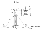
- FIG. 5A schematically shows the state of friction stir welding by the friction stir welding apparatus 1 of the present embodiment, and is a diagram corresponding to FIG. 5B showing the state of friction stir welding by the conventional friction stir welding apparatus. .
- the friction stir welding apparatus 1 includes, as main components, an apparatus main body 2, a swing mechanism section 4 connected to the apparatus main body 2 via a vertical movement drive mechanism section 3, and a rotation mechanism section 6.
- a holder part (joining head) 5 connected to the swing mechanism part 4 and a joining tool part 7 held by the holder part (joining head) 5.
- a ball screw or the like is used for the vertical movement drive mechanism unit 3.
- the joining tool part 7 includes a shoulder 8 and a joining pin 9, and the joining pin 9 is held by a holder part (joining head) 5 through the shoulder 8.
- the joining pin 9 is inserted into the butted portion of the member to be joined 10 and is rotated at a high speed, so that frictional heat is generated between the joining pin 9 and the member to be joined 10, and plastic flow occurs in the member to be joined 10 due to the frictional heat. And the joint is agitated. When the joining pin 9 moves, the stirring portion (joining portion) is cooled, and the members to be joined are joined together.
- the apparatus main body 2 is provided with a control unit (control apparatus) 11 that controls the operation of the friction stir welding apparatus 1.
- the control unit (control device) 11 includes a joining condition signal for determining a joining condition by the joining tool unit 7, a swing control signal for controlling the swing mechanism unit 4, and the height direction of the joining tool unit 7 by the vertical movement drive mechanism unit 3 (
- a storage unit (not shown) for storing a bonding parameter (FSW bonding condition) such as a holding position determination signal for determining a holding position (insertion amount of the bonding pin 9) in the Z direction) is provided.
- FIG. 2 conceptually shows the movement of the holder portion (joining head) 5 in FIG. 1, the horizontal axis indicates the X direction in FIG. 1, and the vertical axis indicates the Z direction (height direction).
- the Z direction (height direction) of the holder portion (joining head) 5 from the friction stir welding start point (t s ) to the friction stir welding end point (t e ). ) Position is kept constant. (Second line from the top in FIG.
- the friction stir welding apparatus 1 of the present embodiment while correcting the position of the friction stir joining starting point holder at predetermined intervals from (t s) Z direction (height direction) of the (joint head) 5 Holder
- the part (joining head) 5 is swung (moved) in the X direction.
- FIG. 2 Uppermost line in FIG. 2
- correction is made at t 1 , t 2 , and t 3 from the friction stir welding start point (t s ) and every certain elapsed time.
- the bonding mode at the start point t S is the first bonding mode
- the bonding mode at t 1 is the second bonding mode
- the bonding mode at t 2 is the third bonding mode
- the bonding mode at t 3 is (The fourth joining mode is entered.)
- the distal end portion (joining pin 9) of the joining tool portion 7 swings along a locus as indicated by the second line from the bottom of FIG.
- the joint point (joint surface) of the members to be joined is horizontal.
- the friction stir welding apparatus 1 In the operation of the friction stir welding apparatus 1 shown in FIG. 2, from an example is shown in which the junction point between the bonded members (bonding surface) is controlled to be horizontal, the friction stir joining starting point (t s) By controlling the operation of the welding tool unit 7 so as to include a plurality of bonding modes in one bonding operation (one bonding pass: pass) between the friction stir welding end points (t e ), the bonding end to the bonding end It is possible to arbitrarily control the position of the joining point (joining surface) of the member to be joined.
- the position of the bonding tool portion 7 in the Z direction (height direction) can be controlled in accordance with the change in the vertical position of the bonding interface. It is possible to obtain a highly accurate and highly reliable bonding interface.
- the operation (action) shown in FIG. 2 described above is previously stored in the storage unit of the control unit (control device) 11 in accordance with the state of the member to be joined 10 such as the material, shape (size, length), plate thickness, and the like.
- the control (control device) 11 controls the operation of the friction stir welding device 1 based on the stored (registered) welding parameters shown in FIG.
- the FSW joining conditions include the number of revolutions (N) of the joining tool, the amount of insertion of the joining tool (Z 1 ), that is, the Z direction (height of the holder part (joining head) 5. position direction), the swing amount of the welding tool (L, T, theta), swing speed of the welding tool (V), the insertion speed of the welding tool (Vp), retention time after the welding tool inserted into the joint (T h ) And the like.
- the control of the friction stir welding apparatus 1 is not limited to the FSW welding conditions (joining parameters) shown in FIG. 3 and may include other joining parameters. Also, although an example of correcting the position of the holder portion (bonding head) 5 in the Z direction (height direction) in accordance with the friction stir joining starting point in FIG. 2 (t s) the elapsed time from the (T), For example, among the joining parameters shown in FIG. 3, the Z direction (high) of the holder part (joining head) 5 according to the swing distance (L), swing angle ( ⁇ ), and swing angular velocity of the joining tool part (swing mechanism part 4). (Position) may be corrected.
- the position correction of the holder part (joining head) 5 in the Z direction (height direction) is performed based on a plurality of holding position determination signals stored (registered) in advance in the storage part of the control part (control device) 11. state and friction stir joining starting point (t s) the elapsed time from the (T), the swing distance of the welding tool portion (swing mechanism 4) (L), a swing angle (theta), by selecting according to the swing angular velocity You may go.
- the welding tool unit 7 is inserted into a predetermined position of the bonding part of the member to be bonded 10 (butting part between the members to be bonded). (Step S1) Next, the welding tool part 7 is swung (moved) along the joining part of the member to be joined 10 while controlling the height (position in the Z direction) of the joining tool part 7 according to a command from the control unit (control device) 11. ) And friction stir welding the joint.
- Step S2 Subsequently, when the swing amount (movement amount in the X direction) of the welding tool unit 7 reaches a predetermined value (position) according to a command from the control unit (control device) 11, the welding tool unit 7 is connected to the member 10 to be bonded.
- the friction stir welding process is terminated by pulling out from the joint.
- Step S3 As described above, according to the friction stir welding apparatus and the friction stir welding method of the present embodiment, the position in the depth direction (Z direction) of the welding tool tip with respect to the member to be joined is changed from the friction stir welding start to the friction stir welding.
- the depth of the joint can be controlled to be constant without changing until the end.
- Friction stir welding can be performed with high accuracy, and the bonding reliability of the bonded portion is improved.
- the insertion depth of the joining tool portion can be controlled so that the temperature at the joining interface between the resin member and the metal material is constant.
- FIG. 6 shows the overall outline of the friction stir welding apparatus 21 of this embodiment
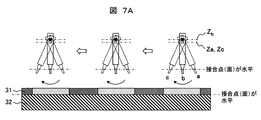
- FIG. 7A schematically shows the state of the friction stir welding by the friction stir welding apparatus 21
- FIG. 7B is a view showing a state of friction stir welding by a conventional friction stir welding apparatus, and is shown for explanation in comparison with FIG. 7A.
- the friction stir welding apparatus 21 includes, as main components, a multi-axis robot 22, a C-type frame 23, and a C-type frame 23 via a vertical movement drive mechanism (ball screw) 24 that is a lifting device.
- a swing mechanism portion 25 to be connected, a holder portion (joining head) 26 connected to the swing mechanism portion 25 via a rotation mechanism portion 27, and a joining tool portion 28 held by the holder portion (joining head) 26 are provided.
- the joining tool part 28 includes a shoulder 29 and a joining pin 30, and the joining pin 30 is held by a holder part (joining head) 26 via the shoulder 29.
- the multi-axis robot 22 is a vertical articulated robot generally called a robot arm, and can freely move (move) in a three-dimensional space by an articulated structure and a servo motor. Although the movable range varies depending on the number of joints (number of axes), an example of a three-axis type robot arm having a lower arm portion 22b, an upper arm portion 22c, and a wrist portion 22d on the pedestal portion 22a is shown here. A white circle portion of the multi-axis robot 22 is a joint.
- the friction stir welding apparatus 21 includes a control device (not shown) in which a servo amplifier, a substrate, and the like are housed, and the movement of the multi-axis robot 22 is comprehensively determined by a command (program signal) from the control device. To control.
- a substantially C-shaped (or substantially U-shaped) C-shaped frame 23 is connected to the tip of the wrist portion 22d of the multi-axis robot 22 via a joint.
- the C-type frame 23 is connected to the tip of the wrist portion 22d, and holds the C-type frame 23 itself on the multi-axis robot 22, and is connected to one end of the holding portion 23a to move up and down.
- a swing mechanism holding portion 23b that holds the swing mechanism portion 25 via a drive mechanism portion (ball screw) 24 is connected to the other end of the holding portion (upper portion) 23a to receive a pressing force from the joining tool portion 28. It is comprised from the pressing force receiving part 23c.
- FIG. 6 shows an example in which the holding portion (upper portion) 23a, the swing mechanism holding portion 23b, and the pressing force receiving portion 23c constitute the C-shaped frame 23 as an integrated body, but each part is formed as a separate body.
- An example in which the C-shaped frame 23 is configured by combining them is also included.
- the swing mechanism unit 25 is connected to the swing mechanism holding unit 23b via a vertical movement drive mechanism unit (ball screw) 24, and is up and down with respect to the swing mechanism holding unit 23b (here, the Z direction in FIG. 6). To work.
- the holder part (joining head) 26 is connected to the swing mechanism part 25 via the rotation mechanism part 27, and swings in the front-rear direction (here, the X direction in FIG. 6) with respect to the swing mechanism part 25. .
- the joining tool portion 28 includes a shoulder 29 and a joining pin 30.
- the joining tool portion 28 is inserted into a member to be joined to a predetermined depth while rotating the joining pin 30 at a high speed, and is moved along the joining portion (joining line). Join.
- the friction stir welding apparatus 21 of the present embodiment is similar to the first embodiment in that the holder portion (joining head) 26 is interposed via the vertical movement drive mechanism portion 24, the swing mechanism portion 25, and the rotation mechanism portion 27. And the joining tool portion 28 are connected to the C-shaped frame 23 (device main body), and when performing friction stir welding, the tip end portion (joining pin 30) of the joining tool portion 28 is swung in the X direction of FIG. The position in the Z direction (height direction) can be controlled.
- FIG. 7A schematically shows a state in which a composite material of a steel material (frame material) 32 and aluminum (AL) 32 is intermittently spot-bonded by the friction stir welding apparatus 21 of the present embodiment.
- the height position in the Z direction; the position in the Z direction
- the vertical movement drive mechanism 24 Z c controlling the vertical movement drive mechanism 24 Z c.
- the holder portion (joining head) 26 and the joining tool portion 28 are connected to the C-type frame 23 via the vertical movement drive mechanism portion 24, the swing mechanism portion 25, and the rotation mechanism portion 27,
- the joint point (joint surface) can be freely moved in the three-dimensional space.
- positioned three-dimensionally like the body of a motor vehicle and includes a curved surface can be performed accurately.
- this invention is not limited to an above-described Example, Various modifications are included.
- the above-described embodiments have been described in detail for easy understanding of the present invention, and are not necessarily limited to those having all the configurations described.
- a part of the configuration of one embodiment can be replaced with the configuration of another embodiment, and the configuration of another embodiment can be added to the configuration of one embodiment.
- the present invention also has the following features.
- Friction stirring using a friction stir welding apparatus including a device main body and a joining tool portion that is provided with a holder portion in a swing mechanism portion provided in a vertical movement drive mechanism portion of the device main body and held by the holder portion
- a joining method a first holding position determination value for determining a first holding position of the vertical movement drive mechanism, and a plurality of second holding position determination values determined in accordance with an elapsed time after the start of joining.
- the step of starting the friction stir welding based on the joining conditions and the opening of the friction stir welding while swinging the swing mechanism based on the swing control conditions And a step of repeating the friction stir welding based on the joining conditions by changing the holding position of the vertical movement drive mechanism based on the second holding position determination value corresponding to the elapsed time when a predetermined time has passed.
- Friction stir welding apparatus 2 ... Apparatus main body, 3 ... Vertical motion drive mechanism part (ball screw), 4 ... Swing mechanism part, 5 ... Holder part (joining head), 6 ... Turning mechanism part, 7 ... Joining tool , 8 ... shoulder, 9 ... joining pin, 10 ... member to be joined, 11 ... control unit (control device), 21 ... friction stir welding device, 22 ... multi-axis robot, 22a ... pedestal part, 22b ... lower arm part, 22c ... upper arm part, 22d ... wrist part, 23 ... C-shaped frame, 23a ... holding part (upper part), 23b ... swing mechanism holding part, 23c ... pressing force receiving part, 24 ...
Landscapes
- Engineering & Computer Science (AREA)
- Mechanical Engineering (AREA)
- Physics & Mathematics (AREA)
- Optics & Photonics (AREA)
- Pressure Welding/Diffusion-Bonding (AREA)
Abstract
Description
(1)装置本体2に固定されたスイング機構部4の回動機構部6を中心点として、当該中心点(回動機構部6)から接合ツール部7の先端部までの長さをrとして、
(2)接合ツール部7の先端部が鉛直下方の状態(下死点)にある時の中心線と接合ツール部7の先端部とを結ぶ直線との交点に生じる角度をθとすると、
(3)摩擦撹拌接合する時には、接合ツール部7の先端部は、摩擦撹拌接合開始から摩擦撹拌接合終了までrを半径として2θ分の円弧を描くこととなる。
次に、制御部(制御装置)11の指令により、接合ツール部7の高さ(Z方向の位置)を制御しながら、被接合部材10の接合部に沿って接合ツール部7をスイング(移動)させ、接合部を摩擦撹拌接合する。(ステップS2)
続いて、制御部(制御装置)11の指令により、接合ツール部7のスイング量(X方向の移動量)が所定の値(位置)に達した時点で接合ツール部7を被接合部材10の接合部から引き抜いて、摩擦撹拌接合処理を終了する。(ステップS3)
以上説明したように、本実施例の摩擦撹拌接合装置及び摩擦撹拌接合方法によれば、被接合部材に対する接合ツール先端部の深さ方向(Z方向)の位置を摩擦撹拌接合開始から摩擦撹拌接合終了まで変動させず、接合部の深さを一定に制御することができる。
例えば、上記した実施例は本発明を分かりやすく説明するために詳細に説明したものであり、必ずしも説明した全ての構成を備えるものに限定されるものではない。また、ある実施例の構成の一部を他の実施例の構成に置き換えることが可能であり、また、ある実施例の構成に他の実施例の構成を加えることも可能である。また、各実施例の構成の一部について、他の構成の追加・削除・置換をすることが可能である。
Claims (15)
- 被接合部材同士を摩擦撹拌接合により接合する摩擦撹拌接合装置であって、
装置本体と、
前記摩擦撹拌接合装置の動作を制御する制御装置と、
上下動駆動機構部を介して前記装置本体に接続されるスイング機構部と、
回動機構部を介して前記スイング機構部に接続されるホルダ部と、
前記ホルダ部に保持される接合ツールと、を備え、
前記制御装置は、前記接合ツールの接合条件を決定する接合条件信号と、前記スイング機構部を制御するスイング制御信号と、前記上下動駆動機構部による前記接合ツールの保持位置を決定する第1の保持位置決定信号と、に基づいて摩擦撹拌接合する第1の接合モードと、
前記接合条件信号と、前記スイング制御信号と、被接合部材の状態に応じて接合部の深さを一定に制御するように前記第1の保持位置決定信号を補正した第2の保持位置決定信号と、に基づいて摩擦撹拌接合する第2の接合モードと、を有し、
前記接合ツールの前記被接合部材への挿入から引き抜きまでの一接合パスに、前記第1の接合モードと前記第2の接合モードを含むことを特徴とする摩擦撹拌接合装置。 - 請求項1に記載の摩擦撹拌接合装置であって、
前記制御装置は、前記第1の接合モード及び前記第2の接合モードのいずれかのモードにより前記接合ツールの接合条件と、前記スイング機構部のスイング制御条件と、前記上下動駆動機構部による前記接合ツールの保持位置を決定することを特徴とする摩擦撹拌接合装置。 - 請求項2に記載の摩擦撹拌接合装置であって、
前記制御装置は、前記第1の接合モードにより被接合部材の摩擦撹拌接合を開始し、所定の時間経過後に、前記第2の接合モードに切り換えることを特徴とする摩擦撹拌接合装置。 - 請求項1に記載の摩擦撹拌接合装置であって、
前記制御装置は、前記接合条件信号と、前記スイング制御信号と、前記第1の保持位置決定信号と、前記第2の保持位置決定信号と、を記憶する記憶部を有することを特徴とする摩擦撹拌接合装置。 - 請求項4に記載の摩擦撹拌接合装置であって、
前記制御装置は、摩擦撹拌接合開始後の経過時間に応じて決定した前記接合ツールの保持位置を前記記憶部に予め記憶させ、当該記憶した保持位置に基づき前記第2の保持位置決定信号を決定することを特徴とする摩擦撹拌接合装置。 - 請求項5に記載の摩擦撹拌接合装置であって、
前記制御装置は、予め記憶した複数の保持位置決定信号から摩擦撹拌接合開始時からの経過時間に応じて前記第2の保持位置決定信号を決定することを特徴とする摩擦撹拌接合装置。 - 請求項4に記載の摩擦撹拌接合装置であって、
前記制御装置は、前記スイング機構部のスイング距離に応じて決定した保持位置を前記記憶部に予め記憶させ、当該記憶した保持位置に基づき前記第2の保持位置決定信号を決定することを特徴とする摩擦撹拌接合装置。 - 請求項7に記載の摩擦撹拌接合装置であって、
前記制御装置は、予め記憶した複数の保持位置決定信号から摩擦撹拌接合開始時からの前記スイング機構部のスイング距離に応じて前記第2の保持位置決定信号を決定することを特徴とする摩擦撹拌接合装置。 - 請求項4に記載の摩擦撹拌接合装置であって、
前記制御装置は、前記スイング機構部のスイング角度に応じて決定した保持位置を前記記憶部に予め記憶させ、当該記憶した保持位置に基づき前記第2の保持位置決定信号を決定することを特徴とする摩擦撹拌接合装置。 - 請求項9に記載の摩擦撹拌接合装置であって、
前記制御装置は、予め記憶した複数の保持位置決定信号から摩擦撹拌接合開始時からの前記スイング機構部のスイング角度に応じて前記第2の保持位置決定信号を決定することを特徴とする摩擦撹拌接合装置。 - 被接合部材同士を摩擦撹拌接合により接合する摩擦撹拌接合装置であって、
前記摩擦撹拌接合装置の動作を制御する制御装置と、
複数の関節を有し、三次元空間を自在に移動可能な多軸ロボットアームと、
前記多軸ロボットアームの先端に接続されるC型フレームと、
上下動駆動機構部を介して前記C型フレームの一端に接続されるスイング機構部と、
回動機構部を介して前記スイング機構部に接続されるホルダ部と、
前記ホルダ部に保持される接合ツールと、
前記C型フレームの他端に接続され、前記接合ツールからの押圧力を受け止める押圧力受け部と、を備え、
前記制御装置は、前記接合ツールの接合条件を決定する接合条件信号と、前記スイング機構部を制御するスイング制御信号と、前記上下動駆動機構部による前記接合ツールの保持位置を決定する第1の保持位置決定信号と、に基づいて摩擦撹拌接合する第1の接合モードと、
前記接合条件信号と、前記スイング制御信号と、被接合部材の状態に応じて接合部の深さを一定に制御するように前記第1の保持位置決定信号を補正した第2の保持位置決定信号と、に基づいて摩擦撹拌接合する第2の接合モードと、を有し、
前記接合ツールの前記被接合部材への挿入から引き抜きまでの一接合パスに、前記第1の接合モードと前記第2の接合モードを含むことを特徴とする摩擦撹拌接合装置。 - 請求項11に記載の摩擦撹拌接合装置であって、
前記制御装置は、前記第1の接合モード及び前記第2の接合モードのいずれかのモードにより前記接合ツールの接合条件と、前記スイング機構部のスイング制御条件と、前記上下動駆動機構部による前記接合ツールの保持位置を決定することを特徴とする摩擦撹拌接合装置。 - 被接合部材同士を摩擦撹拌接合により接合する摩擦撹拌接合方法であって、
(a)制御部の指令により接合ツールを被接合部材の接合部の所定の位置へ挿入するステップと、
(b)前記制御部の指令により接合部の深さを一定に制御するように前記被接合部材に対する前記接合ツールの高さを制御しながら前記接合部に沿って前記接合ツールをスイングさせ前記接合部を摩擦撹拌接合するステップと、
(c)前記制御部の指令により前記接合ツールのスイング量が所定の位置に達した時点で前記接合ツールを前記接合部から引き抜くステップと、
を有することを特徴とする摩擦撹拌接合方法。 - 請求項13に記載の摩擦撹拌接合方法であって、
前記(b)ステップにおいて、摩擦撹拌接合開始時からの経過時間、前記接合ツールのスイング距離、前記接合ツールのスイング角度のいずれかに応じて予め決定した前記接合ツールの保持位置に基づき、前記接合ツールの高さを制御することを特徴とする摩擦撹拌接合方法。 - 請求項13または14に記載の摩擦撹拌接合方法であって、
前記被接合部材の接合部に対し、前記(a)ステップから(c)ステップまでを断続的に繰り返すスポット接合であることを特徴とする摩擦撹拌接合方法。
Priority Applications (4)
| Application Number | Priority Date | Filing Date | Title |
|---|---|---|---|
| KR1020207026908A KR102387693B1 (ko) | 2018-03-29 | 2019-03-27 | 마찰 교반 접합 장치 및 마찰 교반 접합 방법 |
| US17/041,035 US11285562B2 (en) | 2018-03-29 | 2019-03-27 | Friction stir welding apparatus and friction stir welding method |
| CN201980015570.9A CN111788031B (zh) | 2018-03-29 | 2019-03-27 | 摩擦搅拌接合装置及摩擦搅拌接合方法 |
| EP19775582.0A EP3778094B1 (en) | 2018-03-29 | 2019-03-27 | Friction stir welding device, and friction stir welding method |
Applications Claiming Priority (2)
| Application Number | Priority Date | Filing Date | Title |
|---|---|---|---|
| JP2018063417A JP6408735B1 (ja) | 2018-03-29 | 2018-03-29 | 摩擦撹拌接合装置及び摩擦撹拌接合方法 |
| JP2018-063417 | 2018-03-29 |
Publications (1)
| Publication Number | Publication Date |
|---|---|
| WO2019189470A1 true WO2019189470A1 (ja) | 2019-10-03 |
Family
ID=63855189
Family Applications (1)
| Application Number | Title | Priority Date | Filing Date |
|---|---|---|---|
| PCT/JP2019/013371 Ceased WO2019189470A1 (ja) | 2018-03-29 | 2019-03-27 | 摩擦撹拌接合装置及び摩擦撹拌接合方法 |
Country Status (6)
| Country | Link |
|---|---|
| US (1) | US11285562B2 (ja) |
| EP (1) | EP3778094B1 (ja) |
| JP (1) | JP6408735B1 (ja) |
| KR (1) | KR102387693B1 (ja) |
| CN (1) | CN111788031B (ja) |
| WO (1) | WO2019189470A1 (ja) |
Families Citing this family (7)
| Publication number | Priority date | Publication date | Assignee | Title |
|---|---|---|---|---|
| JP6408735B1 (ja) | 2018-03-29 | 2018-10-17 | 株式会社日立パワーソリューションズ | 摩擦撹拌接合装置及び摩擦撹拌接合方法 |
| KR102438105B1 (ko) * | 2018-09-19 | 2022-08-31 | 가부시키가이샤 히타치 파워 솔루션즈 | 마찰 교반 접합 장치 |
| AT522421A1 (de) * | 2019-02-25 | 2020-10-15 | Stirtec Gmbh | Verfahren zum Fügen oder Zerspanen sowie Vorrichtung hierzu |
| CN111774774B (zh) * | 2020-06-23 | 2024-08-20 | 吴钩科技(苏州)有限公司 | 一种相贯线法线跟踪机构 |
| JP7619025B2 (ja) * | 2020-12-03 | 2025-01-22 | 日本軽金属株式会社 | 接合装置及び接合方法 |
| CN113828908A (zh) * | 2021-11-17 | 2021-12-24 | 黄山学院 | 一种非直线插补变轨迹搅拌摩擦焊接工艺 |
| CN114951959B (zh) * | 2022-07-04 | 2023-03-24 | 河北科技大学 | 一种搅拌摩擦焊接工具 |
Citations (7)
| Publication number | Priority date | Publication date | Assignee | Title |
|---|---|---|---|---|
| EP0785044A1 (en) * | 1995-12-20 | 1997-07-23 | ROLLS-ROYCE plc | Friction welding apparatus |
| JP2004136331A (ja) * | 2002-10-18 | 2004-05-13 | Hitachi Ltd | 摩擦攪拌接合装置及び接合方法 |
| JP2005313227A (ja) * | 2004-03-31 | 2005-11-10 | Kawasaki Heavy Ind Ltd | 摩擦撹拌接合装置 |
| JP4511526B2 (ja) | 2004-03-19 | 2010-07-28 | 株式会社日立製作所 | 摩擦攪拌スポット接合方法および接合装置 |
| JP2014024095A (ja) * | 2012-07-27 | 2014-02-06 | Nsk Ltd | 摩擦攪拌接合装置及び摩擦攪拌接合方法 |
| DE102014213647A1 (de) * | 2014-07-14 | 2016-01-14 | Robert Bosch Gmbh | Vorrichtung und Verfahren zum Ausbilden einer Schweißverbindung |
| JP6408735B1 (ja) * | 2018-03-29 | 2018-10-17 | 株式会社日立パワーソリューションズ | 摩擦撹拌接合装置及び摩擦撹拌接合方法 |
Family Cites Families (8)
| Publication number | Priority date | Publication date | Assignee | Title |
|---|---|---|---|---|
| JP3763734B2 (ja) * | 2000-10-27 | 2006-04-05 | 株式会社日立製作所 | パネル部材の加工方法 |
| JP4286521B2 (ja) * | 2002-11-22 | 2009-07-01 | 川崎重工業株式会社 | 摩擦撹拌接合方法 |
| GB0400821D0 (en) * | 2004-01-15 | 2004-02-18 | Rolls Royce Plc | Friction welding process |
| US9511461B2 (en) * | 2006-10-05 | 2016-12-06 | The Boeing Company | Independent axis ancillary device |
| US8052034B2 (en) * | 2008-05-30 | 2011-11-08 | Vanderbilt University | Lateral position detection and control for friction stir systems |
| JP2012161809A (ja) * | 2011-02-04 | 2012-08-30 | Nsk Ltd | 摩擦攪拌接合装置及びそれを用いた摩擦攪拌接合方法 |
| JP6040352B2 (ja) | 2011-03-29 | 2016-12-07 | 学校法人近畿大学 | 摩擦攪拌加工装置及び摩擦攪拌加工方法 |
| JP5945348B1 (ja) | 2015-04-10 | 2016-07-05 | 株式会社日立パワーソリューションズ | 摩擦かく拌接合装置、及び、摩擦かく拌接合方法 |
-
2018
- 2018-03-29 JP JP2018063417A patent/JP6408735B1/ja active Active
-
2019
- 2019-03-27 US US17/041,035 patent/US11285562B2/en active Active
- 2019-03-27 EP EP19775582.0A patent/EP3778094B1/en active Active
- 2019-03-27 CN CN201980015570.9A patent/CN111788031B/zh active Active
- 2019-03-27 KR KR1020207026908A patent/KR102387693B1/ko not_active Expired - Fee Related
- 2019-03-27 WO PCT/JP2019/013371 patent/WO2019189470A1/ja not_active Ceased
Patent Citations (7)
| Publication number | Priority date | Publication date | Assignee | Title |
|---|---|---|---|---|
| EP0785044A1 (en) * | 1995-12-20 | 1997-07-23 | ROLLS-ROYCE plc | Friction welding apparatus |
| JP2004136331A (ja) * | 2002-10-18 | 2004-05-13 | Hitachi Ltd | 摩擦攪拌接合装置及び接合方法 |
| JP4511526B2 (ja) | 2004-03-19 | 2010-07-28 | 株式会社日立製作所 | 摩擦攪拌スポット接合方法および接合装置 |
| JP2005313227A (ja) * | 2004-03-31 | 2005-11-10 | Kawasaki Heavy Ind Ltd | 摩擦撹拌接合装置 |
| JP2014024095A (ja) * | 2012-07-27 | 2014-02-06 | Nsk Ltd | 摩擦攪拌接合装置及び摩擦攪拌接合方法 |
| DE102014213647A1 (de) * | 2014-07-14 | 2016-01-14 | Robert Bosch Gmbh | Vorrichtung und Verfahren zum Ausbilden einer Schweißverbindung |
| JP6408735B1 (ja) * | 2018-03-29 | 2018-10-17 | 株式会社日立パワーソリューションズ | 摩擦撹拌接合装置及び摩擦撹拌接合方法 |
Non-Patent Citations (1)
| Title |
|---|
| See also references of EP3778094A4 |
Also Published As
| Publication number | Publication date |
|---|---|
| KR20200120733A (ko) | 2020-10-21 |
| EP3778094A1 (en) | 2021-02-17 |
| CN111788031A (zh) | 2020-10-16 |
| JP2019171436A (ja) | 2019-10-10 |
| JP6408735B1 (ja) | 2018-10-17 |
| CN111788031B (zh) | 2022-02-22 |
| US11285562B2 (en) | 2022-03-29 |
| EP3778094A4 (en) | 2021-12-08 |
| EP3778094B1 (en) | 2025-12-17 |
| US20210138576A1 (en) | 2021-05-13 |
| KR102387693B1 (ko) | 2022-04-18 |
Similar Documents
| Publication | Publication Date | Title |
|---|---|---|
| JP6408735B1 (ja) | 摩擦撹拌接合装置及び摩擦撹拌接合方法 | |
| KR102438105B1 (ko) | 마찰 교반 접합 장치 | |
| WO2019189509A1 (ja) | 摩擦撹拌接合装置及び摩擦撹拌接合方法 | |
| JP6412627B1 (ja) | 摩擦撹拌接合装置、摩擦撹拌接合方法、データベースを備えた摩擦撹拌接合装置、データベースを用いる摩擦撹拌接合方法、摩擦撹拌接合装置の制御装置 | |
| WO2022009928A1 (ja) | 摩擦攪拌点接合装置及び摩擦攪拌点接合方法 | |
| US12370621B2 (en) | Friction stir tool control method and friction stir device | |
| WO2019189505A1 (ja) | 摩擦撹拌接合装置及び摩擦撹拌接合方法 | |
| JP2011206829A (ja) | 溶接ロボットのワイヤ突出長調整方法および装置 | |
| JP6553791B1 (ja) | 摩擦撹拌接合装置及び摩擦撹拌接合方法 | |
| JP2010240664A (ja) | 溶接ロボット及び溶接におけるウィービング動作の制御方法 | |
| Ahanpanjeh et al. | Contribution of process parameters to geometric deviations of the robot for continuous ultrasonic welding process of thermoplastic composites | |
| JP7524096B2 (ja) | 摩擦撹拌接合装置の制御方法および摩擦撹拌接合装置 | |
| CN117817109A (zh) | 一种振镜焊接方法及存储介质 | |
| JP2020049532A (ja) | 摩擦攪拌接合装置及び摩擦攪拌接合方法 | |
| JP6564511B1 (ja) | 摩擦撹拌接合装置及び摩擦撹拌接合方法 | |
| JP6986647B1 (ja) | ロボット型摩擦攪拌接合装置及びその接合ツールの挿入方法 | |
| JP7002689B1 (ja) | ロボット型摩擦攪拌接合装置及びその接合ツールの挿入方法 | |
| JP6608021B1 (ja) | 摩擦攪拌接合装置 | |
| JP6986651B1 (ja) | 摩擦攪拌接合装置、摩擦攪拌接合方法 | |
| KR20120055037A (ko) | 마찰교반용접 제어장치 | |
| JP2022170231A (ja) | 摩擦攪拌接合装置及び接合ツールの挿入量制限方法 | |
| JP2009136903A (ja) | 溶接ロボットの制御装置および制御方法 |
Legal Events
| Date | Code | Title | Description |
|---|---|---|---|
| 121 | Ep: the epo has been informed by wipo that ep was designated in this application |
Ref document number: 19775582 Country of ref document: EP Kind code of ref document: A1 |
|
| ENP | Entry into the national phase |
Ref document number: 20207026908 Country of ref document: KR Kind code of ref document: A |
|
| NENP | Non-entry into the national phase |
Ref country code: DE |
|
| WWE | Wipo information: entry into national phase |
Ref document number: 2019775582 Country of ref document: EP |
|
| ENP | Entry into the national phase |
Ref document number: 2019775582 Country of ref document: EP Effective date: 20201029 |
|
| WWG | Wipo information: grant in national office |
Ref document number: 2019775582 Country of ref document: EP |