WO2019189828A1 - ガイドワイヤ - Google Patents
ガイドワイヤ Download PDFInfo
- Publication number
- WO2019189828A1 WO2019189828A1 PCT/JP2019/014185 JP2019014185W WO2019189828A1 WO 2019189828 A1 WO2019189828 A1 WO 2019189828A1 JP 2019014185 W JP2019014185 W JP 2019014185W WO 2019189828 A1 WO2019189828 A1 WO 2019189828A1
- Authority
- WO
- WIPO (PCT)
- Prior art keywords
- guide wire
- end side
- region
- storage portion
- storage
- Prior art date
- Legal status (The legal status is an assumption and is not a legal conclusion. Google has not performed a legal analysis and makes no representation as to the accuracy of the status listed.)
- Ceased
Links
Images


Classifications
-
- A—HUMAN NECESSITIES
- A61—MEDICAL OR VETERINARY SCIENCE; HYGIENE
- A61B—DIAGNOSIS; SURGERY; IDENTIFICATION
- A61B5/00—Measuring for diagnostic purposes; Identification of persons
- A61B5/02—Detecting, measuring or recording for evaluating the cardiovascular system, e.g. pulse, heart rate, blood pressure or blood flow
- A61B5/021—Measuring pressure in heart or blood vessels
- A61B5/0215—Measuring pressure in heart or blood vessels by means inserted into the body
- A61B5/02154—Measuring pressure in heart or blood vessels by means inserted into the body by optical transmission
-
- A—HUMAN NECESSITIES
- A61—MEDICAL OR VETERINARY SCIENCE; HYGIENE
- A61B—DIAGNOSIS; SURGERY; IDENTIFICATION
- A61B5/00—Measuring for diagnostic purposes; Identification of persons
- A61B5/02—Detecting, measuring or recording for evaluating the cardiovascular system, e.g. pulse, heart rate, blood pressure or blood flow
- A61B5/021—Measuring pressure in heart or blood vessels
- A61B5/0215—Measuring pressure in heart or blood vessels by means inserted into the body
-
- A—HUMAN NECESSITIES
- A61—MEDICAL OR VETERINARY SCIENCE; HYGIENE
- A61B—DIAGNOSIS; SURGERY; IDENTIFICATION
- A61B5/00—Measuring for diagnostic purposes; Identification of persons
- A61B5/68—Arrangements of detecting, measuring or recording means, e.g. sensors, in relation to patient
- A61B5/6846—Arrangements of detecting, measuring or recording means, e.g. sensors, in relation to patient specially adapted to be brought in contact with an internal body part, i.e. invasive
- A61B5/6847—Arrangements of detecting, measuring or recording means, e.g. sensors, in relation to patient specially adapted to be brought in contact with an internal body part, i.e. invasive mounted on an invasive device
- A61B5/6851—Guide wires
-
- A—HUMAN NECESSITIES
- A61—MEDICAL OR VETERINARY SCIENCE; HYGIENE
- A61B—DIAGNOSIS; SURGERY; IDENTIFICATION
- A61B5/00—Measuring for diagnostic purposes; Identification of persons
- A61B5/68—Arrangements of detecting, measuring or recording means, e.g. sensors, in relation to patient
- A61B5/6846—Arrangements of detecting, measuring or recording means, e.g. sensors, in relation to patient specially adapted to be brought in contact with an internal body part, i.e. invasive
- A61B5/6867—Arrangements of detecting, measuring or recording means, e.g. sensors, in relation to patient specially adapted to be brought in contact with an internal body part, i.e. invasive specially adapted to be attached or implanted in a specific body part
- A61B5/6876—Blood vessel
-
- A—HUMAN NECESSITIES
- A61—MEDICAL OR VETERINARY SCIENCE; HYGIENE
- A61M—DEVICES FOR INTRODUCING MEDIA INTO, OR ONTO, THE BODY; DEVICES FOR TRANSDUCING BODY MEDIA OR FOR TAKING MEDIA FROM THE BODY; DEVICES FOR PRODUCING OR ENDING SLEEP OR STUPOR
- A61M25/00—Catheters; Hollow probes
- A61M25/01—Introducing, guiding, advancing, emplacing or holding catheters
- A61M25/09—Guide wires
-
- A—HUMAN NECESSITIES
- A61—MEDICAL OR VETERINARY SCIENCE; HYGIENE
- A61B—DIAGNOSIS; SURGERY; IDENTIFICATION
- A61B2560/00—Constructional details of operational features of apparatus; Accessories for medical measuring apparatus
- A61B2560/04—Constructional details of apparatus
-
- A—HUMAN NECESSITIES
- A61—MEDICAL OR VETERINARY SCIENCE; HYGIENE
- A61B—DIAGNOSIS; SURGERY; IDENTIFICATION
- A61B2562/00—Details of sensors; Constructional details of sensor housings or probes; Accessories for sensors
- A61B2562/02—Details of sensors specially adapted for in-vivo measurements
- A61B2562/0247—Pressure sensors
-
- A—HUMAN NECESSITIES
- A61—MEDICAL OR VETERINARY SCIENCE; HYGIENE
- A61B—DIAGNOSIS; SURGERY; IDENTIFICATION
- A61B5/00—Measuring for diagnostic purposes; Identification of persons
- A61B5/02—Detecting, measuring or recording for evaluating the cardiovascular system, e.g. pulse, heart rate, blood pressure or blood flow
- A61B5/02007—Evaluating blood vessel condition, e.g. elasticity, compliance
-
- A—HUMAN NECESSITIES
- A61—MEDICAL OR VETERINARY SCIENCE; HYGIENE
- A61B—DIAGNOSIS; SURGERY; IDENTIFICATION
- A61B5/00—Measuring for diagnostic purposes; Identification of persons
- A61B5/02—Detecting, measuring or recording for evaluating the cardiovascular system, e.g. pulse, heart rate, blood pressure or blood flow
- A61B5/02028—Determining haemodynamic parameters not otherwise provided for, e.g. cardiac contractility or left ventricular ejection fraction
-
- A—HUMAN NECESSITIES
- A61—MEDICAL OR VETERINARY SCIENCE; HYGIENE
- A61B—DIAGNOSIS; SURGERY; IDENTIFICATION
- A61B5/00—Measuring for diagnostic purposes; Identification of persons
- A61B5/02—Detecting, measuring or recording for evaluating the cardiovascular system, e.g. pulse, heart rate, blood pressure or blood flow
- A61B5/0205—Simultaneously evaluating both cardiovascular conditions and different types of body conditions, e.g. heart and respiratory condition
- A61B5/02055—Simultaneously evaluating both cardiovascular condition and temperature
Definitions
- the present invention relates to a guide wire.
- Patent Literature 1 discloses a pressure detection guide wire including a pressure sensor disposed inside a tubular member.
- a pressure detection guide wire since it is necessary to bring blood into contact with a pressure sensor for detecting blood pressure, in Patent Document 1, by forming a plurality of slots in the tubular member, the inner side of the tubular member is formed. Blood is flowing into.
- Patent Document 2 discloses a tubular member (medical tube) having an annular slot formed in a spiral shape or at a predetermined interval.
- the guide wire since the guide wire is inserted into the blood vessel, the guide wire has a small diameter, and the blood vessel has a complicated curved shape.
- the pressure detection guide wire described in Patent Document 1 or the guide wire using the medical tube described in Patent Document 2 since a plurality of slots are provided in the circumferential direction, the use of the guide wire As a result, stress is concentrated between one slot and another slot, and the tubular member may be separated. If the separated fragments remain in the body with the separation of the tubular member, it is not preferable because it takes time to extract the separated fragments and the body fragments may be damaged by the separated fragments.
- a spiral slot is employed in the medical tube described in Patent Document 2
- torque transmission with respect to a rotation operation in a direction opposite to the spiral winding direction is poor.
- Such a problem is not limited to a guide wire that is inserted into a blood vessel and detects blood pressure, but is inserted into a blood vessel to detect and acquire information on the blood vessel (eg, pressure, temperature, image, etc.).
- a guide wire inserted into each organ in the human body such as lymph gland system, biliary system, urinary tract system, airway system, digestive organ system, secretory gland, and reproductive organ.
- the present invention has been made to solve at least a part of the problems described above, and reduces the risk of disconnection in a guide wire capable of acquiring information related to the vessel in the vessel. Objective.
- the present invention has been made to solve at least a part of the problems described above, and can be realized as the following forms.
- a guide wire includes a detection element that detects information related to the blood vessel in the blood vessel, and an extension unit that extends from the detection element toward the proximal end side of the guide wire and transmits information detected by the detection element.
- a first storage unit that stores the detection element
- a second storage unit that stores the extension unit
- a covering unit that covers the second storage unit.
- a distal end portion of the covering portion is connected to a proximal end portion of the first storage portion.
- the extending portion that transmits information detected by the detection element has a smaller diameter than the detection element that detects information related to the blood vessel.
- the second storage portion that stores the elongated extending portion is further provided with the covering portion that covers the guide portion, even if the second storage portion is damaged, the guide wire is provided by the covering portion. Can be prevented, and fragments can be prevented from remaining in the body.
- the distal end portion of the covering portion is connected to the base end portion of the first storage portion that stores the detection element, the guide wire is prevented from being disconnected at the boundary between the first storage portion and the second storage portion. It is possible to prevent the separated fragments from remaining in the body.
- the distal end portion of the covering portion is connected to the proximal end portion of the first storage portion, it is possible to improve torque transmission with respect to the rotation operation to the guide wire.
- the possibility of disconnection can be reduced in the guide wire that can acquire information related to the blood vessel in the blood vessel.
- the covering portion has an outer diameter at the distal end portion that is substantially equal to an outer diameter at the proximal end portion of the first storage portion, and is arranged substantially coaxially with the first storage portion. May be.
- coated part is arrange
- a reduced diameter portion whose outer diameter gradually decreases from the proximal end side to the distal end side may be formed on the distal end side of the second storage portion.
- the distal end portion of the second storage portion is formed with a reduced diameter portion whose outer diameter gradually decreases from the proximal end side to the distal end side. Compared with the base end side of the second storage portion, it can be configured flexibly.
- a stepped portion that engages with a distal end portion of the covering portion may be formed at a proximal end portion of the first storage portion.
- the shaft portion disposed on the base end side of the second storage portion, and a part of the base end side of the second storage portion and covered with the covering portion.
- covers the part which does not exist, the boundary part of the said 2nd accommodating part and the said shaft part, and the part of the front end side of the said shaft part may be provided.
- a region of the second storage portion that is covered with the covering portion and that is not covered with the base end side covering portion is defined as a first region, and of the second storage portion that is not covered with the covering portion.
- the rigidity of the second area may be equal to or higher than the rigidity of the first area.
- the rigidity of the guide wire can be gradually made flexible from the proximal end side to the distal end side, and a guide wire excellent in supporting force, torque transmission property, and blood vessel selectivity can be provided.
- the base end side covering portion includes a boundary portion between the second storage portion and the shaft portion and both ends thereof (that is, a portion of the base end side of the second storage portion that is not covered with the covering portion, and the shaft portion. Therefore, the durability of the guide wire can be improved by suppressing the occurrence of folds and kinks at the boundary between the second storage portion and the shaft portion.
- the rigidity of the third region is greater than the rigidity of the second region. It may be. According to this configuration, the rigidity of the guide wire can be gradually made flexible from the proximal end side to the distal end side, and a guide wire excellent in supporting force, torque transmission property, and blood vessel selectivity can be provided.
- the rigidity of the fourth region is greater than the rigidity of the third region. It may be. According to this configuration, the rigidity of the guide wire can be gradually made flexible from the proximal end side to the distal end side, and a guide wire excellent in supporting force, torque transmission property, and blood vessel selectivity can be provided.
- the first storage portion, the second storage portion, and the base end side cover portion are formed of a superelastic material, and the cover portion and the shaft portion are The material may be formed of a material that is more easily plastically deformed than the superelastic material.
- the rigidity of the guide wire can be gradually made flexible from the proximal end side to the distal end side.
- the first storage portion and the second storage portion are formed of a superelastic material
- the covering portion, the base end side covering portion, and the shaft portion are The material may be formed of a material that is more easily plastically deformed than the superelastic material.
- the rigidity of the guide wire is gradually made flexible from the base end side to the distal end side. Therefore, it is possible to provide a guide wire excellent in supporting force, torque transmission property, and blood vessel selectivity.
- the covering portion may be a coil body formed by spirally winding one or more strands.
- coated part is a coil body formed by winding one or several strands helically.
- the detection element may be a detection element that detects a pressure of a body fluid flowing in the vascular vessel.
- the guide wire can be configured as a device that detects (measures) blood pressure.
- the guide wire of the above aspect may further include a tip coil that is provided on the tip side of the first storage portion and is formed by spirally winding one or more strands. According to this configuration, since the front end coil is provided on the front end side of the first storage portion and formed by spirally winding one or more strands, the flexibility on the front end side can be improved. The risk of damaging the tissue in the vessel can be reduced.
- the present invention can be realized in various modes, and forms such as a guide wire, a guide wire manufacturing method, and a guide wire manufacturing apparatus capable of acquiring information related to the blood vessel in the blood vessel. Can be realized.
- FIG. 2 is an explanatory diagram illustrating a cross-sectional configuration along line AA in FIG. 1. It is explanatory drawing which illustrated the structure of the intermediate part. It is explanatory drawing which illustrated the structure of the base end part. It is explanatory drawing which illustrated the structure of the intermediate part of the guide wire of 2nd Embodiment. It is explanatory drawing which illustrated the structure of the base end part of the guide wire of 2nd Embodiment. It is explanatory drawing which illustrated the structure of the intermediate part of the guide wire of 3rd Embodiment. It is explanatory drawing which illustrated the structure of the intermediate part of the guide wire of 4th Embodiment.
- FIG. 1 is an explanatory diagram illustrating a cross-sectional configuration of the guide wire 1 according to the first embodiment.
- the guide wire 1 of the present embodiment is a device that is used by being inserted into a blood vessel and capable of detecting blood pressure (intravascular pressure). Based on the blood pressure detected by the guide wire 1, a fractional flow reserve (FFR) can be derived.
- the coronary flow reserve ratio is the pressure behind the stenosis with respect to the pressure before the stenosis, and is used as an index of the severity of physiological stenosis.
- FIG. 1 an axis passing through the center of the guide wire 1 is represented by an axis O (dashed line).
- the axis passing through the center of the guide wire 1 and the axis passing through the center of each member of the guide wire 1 will be described as being coincident with the axis O, but they may be different from each other.
- FIG. 1 also shows XYZ axes that are orthogonal to each other.
- the X axis corresponds to the axial direction of the guide wire 1 (the insertion direction of the guide wire 1)
- the Y axis corresponds to the height direction of the guide wire 1
- the Z axis corresponds to the width direction of the guide wire 1.
- the leading end side of the guide wire 1 and each component member
- the right side of FIG. 1 (+ X axis direction) is referred to as the “proximal end side” of the guide wire 1 and each component member.
- the end portion located on the distal end side and the vicinity thereof are referred to as “the distal end portion” or simply “the distal end”
- the end portion located near the proximal end side and the vicinity thereof are referred to as “the proximal end portion” Or simply “proximal”.
- the distal end side corresponds to a “distal side” inserted into the living body
- the proximal end side corresponds to a “proximal side” operated by an operator such as a doctor.
- the guide wire 1 includes a distal end portion 100, an intermediate portion 200, and a proximal end portion 300.
- the distal end portion 100 is provided on the distal end side of the guide wire 1 and includes a distal end core 101, a distal end tip 105, and a distal end coil 110.
- the distal core 101 is a solid member provided along the axis O of the guide wire 1 and having an outer diameter reduced from the proximal end side to the distal end side.
- the distal end core 101 has a distal end portion 101b provided on the distal end side, a flange portion 101a provided on the proximal end side, and a tapered portion 101c provided between the distal end portion 101b and the flange portion 101a.
- the tip portion 101b is a substantially cylindrical member having a substantially constant outer diameter, and is annealed (annealed) from the tip portion 101b to an intermediate portion of the tapered portion 101c.
- the flange portion 101a is a substantially cylindrical member having a substantially constant outer diameter larger than that of the tip portion 101b.
- the taper portion 101c is a member having an outer diameter smaller than that of the flange portion 101a on the proximal end side, and the outer diameter gradually decreasing from the proximal end side to the distal end side.
- the tip core 101 is made of a superelastic material such as a NiTi (nickel titanium) alloy or an alloy of NiTi and another metal.
- the distal coil 110 is provided so as to surround the distal core 101 in the circumferential direction of the guide wire 1 and has a substantially constant outer diameter from the proximal end side to the distal end side.
- the tip coil 110 has a first coil body 102 disposed on the inner side and a second coil body 103 disposed on the outer side.
- the first coil body 102 is a single-strand stranded coil formed by winding a stranded wire obtained by twisting a plurality of strands into a single strip.
- the second coil body 103 is a single coil formed by winding a single wire into a single thread.
- Each of the first coil body 102 and the second coil body 103 may be a single coil formed by winding a single strand into a single strip, and a plurality of strands may be formed into multiple strips. It may be a multi-strand coil formed by winding, may be a single-strand stranded coil formed by winding a stranded wire obtained by twisting a plurality of strands into a single strip, and a plurality of A multi-strand wire coil formed by using a plurality of twisted wires obtained by twisting strands and winding each twisted wire in multiple strands may be used.
- the first coil body 102 and the second coil body 103 correspond to “tip coils”.
- the proximal end portion of the first coil body 102 and the proximal end portion of the second coil body 103 are joined to the proximal end portion of the tapered portion 101c of the distal end core 101 by the joining portion 106, respectively.
- an arbitrary joining agent for example, a metal solder such as silver solder, gold solder, zinc, Sn—Ag alloy, Au—Sn alloy, or an adhesive such as an epoxy adhesive can be used.
- the wire diameter of the second coil body 103 is larger than the wire diameter of the first coil body 102.
- both wire diameters may be substantially the same, and the wire diameter of the second coil body 103 may be smaller than the wire diameter of the first coil body 102.
- the first coil body 102 and the second coil body 103 are made of a material that is more easily plastically deformed than a superelastic material, for example, a stainless alloy such as SUS304 or SUS316.
- the distal tip 105 is disposed at the distal end portion 100 of the guide wire 1 and joins the distal end portion of the distal core 101 (tip core 101), the distal end portion of the first coil body 102, and the distal end portion of the second coil body 103. And hold it together.
- the tip chip 105 can be formed of an arbitrary bonding agent, for example, a metal solder such as silver solder, gold solder, zinc, Sn—Ag alloy, Au—Sn alloy, or an adhesive such as an epoxy adhesive.
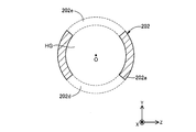
- FIG. 2 is an explanatory diagram illustrating a cross-sectional configuration along the line AA in FIG.
- FIG. 3 is an explanatory diagram illustrating the configuration of the intermediate unit 200.
- the intermediate portion 200 is provided between the distal end portion 100 and the proximal end portion 300 of the guide wire 1, and includes a sensor 201, a storage portion 202, a hollow stranded wire 203, and the like. And a coating layer 204.
- the sensor 201 is an optical pressure sensor that is disposed along the axis O of the guide wire 1 on the proximal end side of the distal core 101 and detects the pressure of body fluid flowing in the blood vessel.
- the sensor 201 has a sensor head 201a provided at the distal end portion and a sensor cable 201b provided on the proximal end side.
- the sensor head 201a is a detection element (microchip) that detects blood pressure by a Fabry-Perot resonator that modulates the wavelength of light in response to a change in external pressure.
- the sensor head 201a may be an optical detection element that detects blood pressure by means other than a Fabry-Perot resonator, or may be a non-optical detection element.
- the sensor cable 201b is an optical fiber that transmits information detected by the sensor head 201a.
- the sensor cable 201b is connected to the sensor head 201a at the distal end portion, extends from the sensor head 201a toward the proximal end side of the guide wire 1, and is connected to a control device and a display device (not shown) at the proximal end portion.
- the sensor 201 corresponds to a “detection unit”
- the sensor head 201a corresponds to a “detection element”
- the sensor cable 201b corresponds to an “extension unit”.
- the storage unit 202 is a member that protects the sensor 201 by storing the sensor 201 (the sensor head 201a and the sensor cable 201b) inside.
- the storage portion 202 has a housing portion 202a disposed on the distal end side, a proximal end portion 202c provided on the proximal end side, and an intermediate portion 202b provided between the housing portion 202a and the proximal end portion 202c. is doing.
- the housing portion 202a is a substantially bottomed cylindrical member having substantially the same outer diameter as the second coil body 103.
- the sensor head 201a is accommodated in the inner space HG of the housing portion 202a.
- the side surface of the housing portion 202 a has a through hole (a hole in the inside and outside of the housing portion 202 a communicating with a part in the axis O direction (X-axis direction) and a part in the circumferential direction.
- a first hole 202d and a second hole 202e are formed.
- the first hole 202d and the second hole 202e function as blood flow paths that allow blood in the blood vessel to flow into the inner space HG in which the sensor head 201a is housed when the guide wire 1 is used. Further, as shown in FIGS. 1 and 3, a through hole for inserting the sensor cable 201b is formed in the bottom surface of the housing portion 202a.
- a housing front end 202f without a communication hole is provided at the front end of the housing 202a.
- the inner side surface of the housing front end portion 202f and the flange portion 101a of the front end core 101 are joined by the first joint portion 109.
- the first joint portion 109 can be formed by laser welding of the housing front end portion 202f and the flange portion 101a.
- the first bonding portion 109 may be formed of any bonding agent or adhesive.
- the intermediate part 202b is a substantially cylindrical member having an outer diameter smaller than that of the housing part 202a.
- the inner cavity of the intermediate portion 202b communicates with the through hole in the bottom surface of the housing portion 202a, and the sensor cable 201b is accommodated.
- a first tapered portion 202x whose outer diameter is gradually reduced from the proximal end side to the distal end side is provided on the distal end side of the intermediate portion 202b.
- a second tapered portion 202y On the proximal end side of the intermediate portion 202b, a second tapered portion 202y whose outer diameter gradually increases from the proximal end side to the distal end side is provided.
- the base end portion 202c is a substantially cylindrical member having an outer diameter thinner than that of the intermediate portion 202b.
- the lumen of the base end portion 202c communicates with the lumen of the intermediate portion 202b and houses the sensor cable 201b.
- the storage portion 202 including the housing portion 202a, the intermediate portion 202b, and the base end portion 202c is formed of a superelastic material, for example, a NiTi alloy or an alloy of NiTi and another metal.
- the housing portion 202a corresponds to a “first storage portion”
- the intermediate portion 202b and the base end portion 202c correspond to a “second storage portion”
- the first taper portion 202x corresponds to a “reduced diameter portion”.
- the hollow stranded wire 203 is provided so as to surround the intermediate portion 202b and the proximal end portion 202c in the circumferential direction of the guide wire 1, and covers the intermediate portion 202b, the proximal end portion 202c, and the distal end portion of the shaft 302. Yes.
- the hollow stranded wire 203 of the present embodiment is a multi-strand coil formed by winding a plurality of strands 203 s into a multi-strand.
- the hollow stranded wire 203 may be a single coil formed by winding a single strand into a single strip, or formed by winding a stranded strand obtained by twisting a plurality of strands into a single strip.
- the hollow portion 203h of the hollow stranded wire 203 accommodates the intermediate portion 202b, the proximal end portion 202c, and the distal end portion of the shaft 302.
- the distal end portion of the hollow stranded wire 203 and the proximal end portion of the housing portion 202a are connected (joined) by the second joint portion 209.
- the second bonding portion 209 can be formed of an arbitrary bonding agent, for example, a metal solder such as silver brazing, gold brazing, zinc, Sn—Ag alloy, Au—Sn alloy, or an adhesive such as an epoxy adhesive.
- a metal solder such as silver brazing, gold brazing, zinc, Sn—Ag alloy, Au—Sn alloy, or an adhesive such as an epoxy adhesive.
- the hollow stranded wire 203 corresponds to a “coating portion”.
- the hollow stranded wire 203 has at least an outer diameter at the distal end (the maximum outer diameter of the strand) substantially the same as an outer diameter at the base end of the housing portion 202a, and the hollow stranded wire 203 and the housing portion 202a Are substantially coaxially arranged side by side in the direction of the axis O.
- the outer diameter of the hollow stranded wire 203 is the same as the outer diameter of the proximal end portion of the housing portion 202a in the entire region from the distal end side to the proximal end side, and the hollow stranded wire 203 And the housing portion 202a are arranged side by side in the direction of the axis O about the axis O.
- the hollow stranded wire 203 is made of, for example, a material that is more easily plastically deformed than a superelastic material, for example, a stainless alloy such as SUS304 or SUS316.
- the coating layer 204 is a hydrophilic coating layer that covers the hollow stranded wire 203.
- the covering layer 204 includes a hollow stranded wire 203, a second joint 209 disposed at the distal end of the hollow stranded wire 203, and a third joint disposed at the proximal end of the hollow stranded wire 203. Part 309a.
- the covering layer 204 can be formed of a hydrophilic resin such as urethane, polyimide, or nylon.
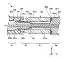
- FIG. 4 is an explanatory view illustrating the configuration of the base end portion 300.
- the base end portion 300 is provided on the base end side of the guide wire 1, and includes a hollow shaft 301, a shaft 302, and a base end side coating layer 304.
- the hollow shaft 301 is a member that protects the sensor cable 201b by housing the sensor cable 201b therein.
- the hollow shaft 301 has a distal end portion 301a disposed on the distal end side and a proximal end portion 301b continuous on the proximal end side.
- the distal end portion 301 a is a substantially cylindrical member having substantially the same bending rigidity as the proximal end portion 202 c of the storage portion 202.
- the hollow shaft 301 is connected to the shaft 302, and the shaft 302 is connected to the storage portion 202. That is, the hollow shaft 301 and the storage unit 202 are connected via the shaft 302.
- an arbitrary bonding agent for example, a metal such as silver brazing, gold brazing, zinc, Sn—Ag alloy, Au—Sn alloy, etc.
- An adhesive such as solder or an epoxy adhesive can be used.
- solder or an epoxy adhesive can be used for example, a metal such as silver brazing, gold brazing, zinc, Sn—Ag alloy, Au—Sn alloy, etc.
- the distal end portion of the distal end portion 301a and the proximal end portion of the proximal end portion 202c of the storage portion 202 are not connected, but may be connected.
- the boundary portion between the distal end portion of the distal end portion 301a and the proximal end portion of the proximal end portion 202c is also referred to as “boundary portion BP” (FIG. 4).
- the lumen of the distal end portion 301a communicates with the lumen of the proximal end portion 202c of the storage portion 202, and the sensor cable 201b is stored.
- a tapered portion 301x whose outer diameter is gradually reduced from the proximal end side to the distal end side is provided on the proximal end side of the distal end portion 301a.
- the base end portion 301 b is a substantially cylindrical member having substantially the same outer diameter as the shaft 302.
- the lumen of the proximal end portion 301b communicates with the lumen of the distal end portion 301a and houses the sensor cable 201b.
- the hollow shaft 301 including the distal end portion 301a, the tapered portion 301x, and the proximal end portion 301b is formed of a material that is more easily plastically deformed than a superelastic material, for example, a stainless alloy such as SUS304 or SUS316.
- the hollow shaft 301 corresponds to a “shaft portion”.
- the shaft 302 is a member that protects the boundary portion BP by covering the vicinity of the boundary portion BP between the storage portion 202 and the hollow shaft 301 and causes the guide wire 1 to gradually change in rigidity.
- the shaft 302 is a part of the base end side of the storage part 202 and is not covered by the hollow stranded wire 203 (that is, the base end part 202 c), and the storage part 202 and the hollow shaft 301.
- the boundary portion BP and a part of the small diameter on the tip side of the hollow shaft 301 that is, the tip portion 301a) are covered.
- the shaft 302 has a tapered portion 302x formed on the distal end side and a proximal end portion 302a formed on the proximal end side.
- the base end portion 302 a is a substantially cylindrical member having substantially the same outer diameter as the base end portion 301 b of the hollow shaft 301 and having an inner diameter smaller than that of the hollow stranded wire 203.
- the tapered portion 302x is a portion whose outer diameter is reduced from the proximal end side to the distal end side. As shown in FIG. 4, a part on the tip side of the tapered portion 302 x enters the inside of the hollow stranded wire 203. The outer surface of the taper portion 302x and the proximal end portion of the hollow stranded wire 203 are joined by a third joint portion 309a. From the taper part 302x, the inner surface of the base end part 302a and the outer side surface of the base end part 202c of the storage part 202 are joined by the fourth joint part 309b.
- the third and fourth joints 309a and 309b are made of an arbitrary joining agent, for example, a metal solder such as silver brazing, gold brazing, zinc, Sn—Ag alloy, Au—Sn alloy, or an adhesive such as an epoxy adhesive. Can be formed.
- the third joint 309a can be formed by laser welding of the hollow shaft 301 and the shaft 302. You may form the 3rd junction part 309a with arbitrary junction agents and adhesives.
- the shaft 302 including the tapered portion 302x and the base end portion 302a is made of a material that is more easily plastically deformed than a superelastic material, for example, a stainless alloy such as SUS304 or SUS316.
- the shaft 302 corresponds to a “base end side covering portion”.
- a region where the storage portion 202 is covered with the hollow stranded wire 203 and is not covered with the shaft 302 is defined as a first region A1.
- a region where the storage portion 202 is covered by the shaft 302 and is not covered by the hollow stranded wire 203 is defined as a second region A2.
- a region where the hollow shaft 301 is covered with the shaft 302 is defined as a third region A3.
- a region where the hollow shaft 301 is not covered with the shaft 302 is defined as a fourth region A4.
- the rigidity of the second area A2 is equal to or greater than the rigidity of the first area A1.
- the rigidity of the third region A3 is equal to or higher than the rigidity of the second region A2.
- the rigidity of the fourth area A4 is greater than or equal to the rigidity of the third area A3. That is, the rigidity of the first to fourth regions gradually increases from the distal end side toward the proximal end side (stiffness A1 ⁇ A2 ⁇ A3 ⁇ A4).
- a difference in rigidity includes a difference in diameter of the storage portion 202 between the first and second regions A1 and A2, a difference in material of the storage portion 202 and the hollow shaft 301 between the second and third regions A2 and A3, This is caused by the difference in the diameter of the shaft 302 between the second and third regions A2 and A3 and the difference in the diameter of the hollow shaft 301 between the third and fourth regions A3 and A4.
- the base end side coating layer 304 is a fluororesin coating layer that covers the space from the fifth joint 309 c to the base end of the hollow shaft 301.
- the base end side coating layer 304 can be formed of, for example, a fluorine resin such as PTFE, PFA, FEP.
- a sensor cable 201b extended portion
- a sensor head 201a detection element
- the hollow stranded wire 203 covering further covering the intermediate part 202b and the base end part 202c (second storing part) of the storing part 202 that stores the small-diameter sensor cable 201b. Part).
- the guide wire 1 can be prevented from being disconnected by the hollow stranded wire 203, so that the separated fragment is in the body. It can suppress remaining.
- the distal end portion of the hollow stranded wire 203 is connected to the base end portion of the housing portion 202a (first storage portion) of the storage portion 202 that stores the sensor head 201a. For this reason, the disconnection of the guide wire 1 at the boundary between the housing portion 202a and the intermediate portion 202b can be suppressed, and the separation fragment can be suppressed from remaining in the body.
- the distal end portion of the hollow stranded wire 203 is connected to the proximal end portion of the housing portion 202a, so that torque transmission with respect to the rotation operation to the guide wire 1 can be improved.
- the guide wire 1 of the first embodiment the guide wire capable of acquiring information on the blood vessel (blood pressure, coronary blood flow reserve ratio in the example of the first embodiment) in the blood vessel. 1, the possibility of disconnection can be reduced.
- the hollow stranded wire 203 (covering portion) has an outer diameter at the distal end portion that is substantially equal to an outer diameter at the proximal end portion of the housing portion 202a (first storage portion) and is substantially the same as the housing portion 202a. They are arranged along the same axis (centered on the axis O) (in the direction of the axis O). For this reason, the outer surface shape L (FIG.
- a first tapered portion 202 x (contracted) whose outer diameter gradually decreases from the proximal end side to the distal end side is provided at the distal end portion of the intermediate portion 202 b (second storage portion) of the storage portion 202. Therefore, the distal end portion of the intermediate portion 202b can be configured more flexibly than the proximal end side of the intermediate portion 202b.
- the hollow stranded wire 203 (covering portion) of the intermediate portion 202b and the base end portion 202c (second storage portion) of the storage portion 202 is not covered with the shaft 302 (base end side covering).
- Area) (the second area A2) is covered by the hollow twisted wire 203 of the intermediate part 202b and the base end part 202c of the storage part 202 and is not covered by the shaft 302. It is more than the rigidity of (1st field A1).
- the rigidity of the region (third region A3) covered with the shaft 302 in the hollow shaft 301 (shaft portion) is equal to or higher than the rigidity of the second region A2.
- the rigidity of the hollow shaft 301 (shaft portion) that is not covered by the shaft 302 (fourth area A4) is equal to or higher than the rigidity of the third area A3.
- the rigidity of the guide wire 1 can be gradually made flexible from the proximal end side to the distal end side, and the guide wire 1 excellent in supporting force, torque transmission property, and blood vessel selectivity can be provided.
- the shaft 302 includes a boundary portion BP between the storage portion 202 and the hollow shaft 301 and both ends thereof (that is, a portion that is a portion on the proximal end side of the storage portion 202 and is not covered with the hollow stranded wire 203; Therefore, the durability of the guide wire 1 can be improved by suppressing the occurrence of folds and kinks at the boundary portion BP between the storage portion 202 and the hollow shaft 301.
- the housing portion 202a (first storage portion) and the intermediate portion 202b of the storage portion 202 are used. And the fracture durability in the base end part 202c (2nd accommodating part) can be improved.
- a super alloy such as SUS304, SUS316 or the like is used for example.
- the rigidity of the guide wire 1 can be gradually made flexible from the proximal end side to the distal end side, and excellent in supporting force, torque transmission property, and blood vessel selectivity.
- a guide wire 1 can be provided.
- the shaft 302 (covering portion) is a coil body formed by winding one or more strands in a spiral shape. For this reason, even if the shaft 302 and both the intermediate portion 202b and the base end portion 202c (second storage portion) of the storage portion 202 are damaged, the shaft 302 can be unwound. Since it stays extending
- the guide wire 1 can be configured as a device that detects (measures) blood pressure.
- the front end coil 110 is provided on the front end side of the housing portion 202a (first storage portion) and formed by spirally winding one or more strands, the flexibility on the front end side is improved. This can reduce the risk of damaging tissue in the vessel.
- FIG. 5 is an explanatory diagram illustrating the configuration of the intermediate portion 200 of the guide wire 1A of the second embodiment.
- a guide wire 1 ⁇ / b> A according to the second embodiment includes a storage portion 202 ⁇ / b> A instead of the storage portion 202 in the intermediate portion 200.
- a stepped portion 202n for engaging the distal end portion of the hollow stranded wire 203 is formed at the proximal end portion of the housing portion 202a.
- the stepped portion 202n is a notch formed in the bottom corner of the housing portion 202a, and extends in the circumferential direction of the guide wire 1A.
- the hollow stranded wire 203 is joined by the second joining portion 209 in a state where the tip end portion is engaged with the stepped portion 202n of the storage portion 202A.
- FIG. 6 is an explanatory diagram illustrating the configuration of the base end portion 300 of the guide wire 1A according to the second embodiment.
- a guide wire 1 ⁇ / b> A of the second embodiment includes a shaft 302 ⁇ / b> A in place of the shaft 302 at the proximal end portion 300.
- the shaft 302A is formed of a material different from that of the first embodiment, specifically, a superelastic material such as a NiTi alloy or an alloy of NiTi and another metal.
- a region where the storage portion 202A is covered with the hollow stranded wire 203 and is not covered with the shaft 302A is defined as a first region A11.
- a region where the storage portion 202A is covered with the shaft 302A and not covered with the hollow stranded wire 203 is referred to as a second region A21.
- a region where the hollow shaft 301 is covered with the shaft 302A is defined as a third region A31.
- a region where the hollow shaft 301 is not covered with the shaft 302A is defined as a fourth region A41.
- the rigidity of the second area A21 is equal to or higher than the rigidity of the first area A11.
- the rigidity of the third area A31 is greater than or equal to the rigidity of the second area A21.
- the rigidity of the fourth area A41 is greater than or equal to the rigidity of the third area A31. (Rigidity A11 ⁇ A21 ⁇ A31 ⁇ A41).
- the shape of the housing portion 202a of the storage portion 202A can be arbitrarily changed.
- a stepped portion 202n for engaging the hollow stranded wire 203 may be provided.
- the housing portion 202a may be formed in a shape other than a substantially bottomed cylindrical shape (for example, a spherical shape having an inner space HG and a through hole that constitutes a blood channel).
- the material of the shaft 302A can be arbitrarily changed.
- a superelastic material as described above may be used, or a resin material may be used. Even if it does in this way, there can exist an effect similar to 1st Embodiment.
- the stepped portion 202n that engages with the distal end portion of the hollow stranded wire 203 (covering portion) is formed at the proximal end portion of the housing portion 202a (first storage portion). Since it is formed, the positioning of the housing portion 202a and the hollow stranded wire 203 during manufacture is facilitated. Further, compared to the configuration without the stepped portion 202n described in the first embodiment, locally at the connection portion (that is, the portion where the second joint portion 209 is provided) between the housing portion 202a and the hollow stranded wire 203. High rigidity can be avoided.
- the shaft 302A base end side covering portion
- the first to fourth regions A11 to A41 are compared to the first embodiment. Can be gradually changed.
- a superelastic material having high fatigue strength such as an NiTi alloy or an alloy of NiTi and another metal
- the housing portion 202a (first storage portion) and the intermediate portion 202b of the storage portion 202A are used. And the fracture endurance in base end part 202c (second storage part) and shaft 302A (base end side covering part) can be improved.
- the rigidity of the guide wire 1A can be gradually made flexible from the proximal end side to the distal end side, and the guide wire 1A excellent in supporting force, torque transmission property, and blood vessel selectivity can be provided.
- FIG. 7 is an explanatory diagram illustrating the configuration of the intermediate portion 200 of the guide wire 1B according to the third embodiment.
- a guide wire 1 ⁇ / b> B of the third embodiment includes a storage portion 202 ⁇ / b> B in place of the storage portion 202 in the intermediate portion 200.
- the outer diameter of the housing portion 202 a is smaller than the outer diameter of the outer diameter of the hollow stranded wire 203. For this reason, in the guide wire 1B, a step (FIG.
- the outer diameter (for example, the tip coil 110, the housing portion 202B, the hollow stranded wire 203, the hollow shaft 301, the shaft 302, etc.) of each component of the guide wire 1B can be arbitrarily changed. Even if it does in this way, there can exist an effect similar to 1st Embodiment.
- FIG. 8 is an explanatory diagram illustrating the configuration of the intermediate portion 200 of the guide wire 1C according to the fourth embodiment.
- the guide wire 1 ⁇ / b> C of the fourth embodiment includes a storage portion 202 ⁇ / b> C in place of the storage portion 202 in the intermediate portion 200.
- the storage portion 202C does not have a reduced diameter portion (FIG. 3: first taper portion 202x) formed at the tip of the intermediate portion 202b.
- the reduced diameter portion and the enlarged diameter portion (for example, the first taper portion 202x and the second taper portion 202y of the storage portion 202C, the taper portion 101c of the tip core 101, and the taper of the shaft 302 in each constituent member of the guide wire 1C.
- the portion 302x, the tapered portion 301x of the hollow shaft 301, etc.) may be omitted. Even if it does in this way, there can exist an effect similar to 1st Embodiment.
- FIG. 9 is an explanatory diagram illustrating the configuration of the base end portion 300 of the guide wire 1D of the fifth embodiment.
- the guide wire 1D of the fifth embodiment does not include the shaft 302 (FIG. 4) and the fifth joint portion 309 c (FIG. 4) at the proximal end portion 300, and replaces the hollow shaft 301 with the hollow shaft 301 ⁇ / b> D. I have.
- the hollow shaft 301D has a distal end portion 301a having an outer diameter substantially the same as that of the hollow stranded wire 203 and having a stepped portion for fitting the proximal end portion 202c of the storage portion 202 on the inner surface thereof, A proximal end portion 301b extending continuously on the proximal end side of the distal end portion 301a.
- the base end portion 202c of the storage portion 202 is joined by the fourth joint portion 309b and the boundary portion BP while being fitted in the stepped portion of the distal end portion 301a.
- a region where the storage portion 202 is covered with the hollow stranded wire 203 is defined as a fifth region A5.
- a region where the storage portion 202 is covered with the hollow shaft 301D is defined as a sixth region A6.
- a region where the hollow shaft 301D does not cover the storage portion 202 is defined as a seventh region A7.
- the rigidity of the sixth region is greater than or equal to the rigidity of the fifth region.
- the rigidity of the seventh region is equal to or greater than the rigidity of the sixth region (stiffness A5 ⁇ A6 ⁇ A7).
- Such a difference in rigidity is caused by a difference in diameter of the storage portion 202 between the fifth to seventh regions A5 to A7 and a difference in diameter of the hollow shaft 301D.
- the configuration of the base end portion 300 can be arbitrarily changed.
- the shaft 302 may be omitted, a plurality of shafts 302 may be provided, and the shape of the hollow shaft 301D may be changed. Also good. Even if it does in this way, there can exist an effect similar to 1st Embodiment.
- FIG. 10 is an explanatory diagram illustrating the configuration of the intermediate portion 200 of the guide wire 1E according to the sixth embodiment.
- a guide wire 1E according to the sixth embodiment includes a storage portion 202E in place of the storage portion 202 in the intermediate portion 200.
- the housing portion 202E has a plurality of first holes 202d and second holes 202e (three sets in the illustrated example) formed in the housing portion 202a.
- the shape of the housing portion 202a of the storage portion 202A can be arbitrarily changed.
- a plurality of sets of the first hole 202d and the second hole 202e may be formed.
- FIG. 11 is an explanatory diagram illustrating the cross-sectional configuration of the guide wire 1F of the seventh embodiment.
- the guide wire 1 ⁇ / b> F of the seventh embodiment does not include the distal end coil 110 (FIG.
- the tip core 101F is provided with the tip 101b directly on the tip of the flange 101a without the taper 101c (FIG. 1). Further, the proximal end portion of the distal tip 105 is joined to the housing distal end portion 202 f of the storage portion 202.
- the configuration of the tip portion 100 can be arbitrarily changed. For example, the tip coil 110 may be omitted, the shape of the tip core 101F may be changed, or the tip tip 105 may be omitted. Good. Even if it does in this way, there can exist an effect similar to 1st Embodiment.
- FIG. 12 is an explanatory diagram illustrating the cross-sectional configuration of the guide wire 1G of the eighth embodiment.
- a guide wire 1G of the eighth embodiment includes a tip coil 110G in place of the tip coil 110 at the tip portion 100.
- the tip coil 110G includes a first tubular body 102G made of a substantially cylindrical tube, instead of the first coil body 102 (FIG. 1) of the coil body.
- the first tubular body 102G may be formed of the same material as the first coil body 102, or may be formed of a resin material.
- the configuration of the tip portion 100 can be arbitrarily changed.
- at least one of the first coil body 102 and the second coil body 103 may be formed of a tubular body, At least one of the first coil body 102 and the second coil body 103 may be omitted. Even if it does in this way, there can exist an effect similar to 1st Embodiment.
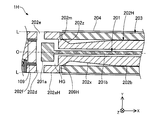
- FIG. 13 is an explanatory diagram illustrating the configuration of the intermediate portion 200 of the guide wire 1H according to the ninth embodiment.
- a guide wire 1H according to the ninth embodiment includes a storage portion 202H instead of the storage portion 202 in the intermediate portion 200.
- the storage portion 202H includes a housing portion 202aH in which a tapered portion 202z and a stepped portion 202m are formed.
- the tapered portion 202z is an inclination formed on the bottom surface of the housing portion 202aH, and is a portion where the outer diameter gradually increases from the proximal end side to the distal end side.
- the stepped portion 202m is a notch provided in the middle of the tapered portion 202z.
- the hollow stranded wire 203 is joined by the second joining portion 209 ⁇ / b> H with the tip portion engaged with the stepped portion 202 m.
- the shape of the housing portion 202aH can be arbitrarily changed, and a tapered portion 202z whose outer diameter gradually increases from the proximal end side to the distal end side may be provided at the proximal end portion of the housing portion 202aH. . Even if it does in this way, there can exist an effect similar to 1st Embodiment. Further, according to the configuration of the ninth embodiment, stress concentration generated between the housing portion 202aH and the first tapered portion 202x can be reduced by providing the tapered portion 202z at the base end portion of the housing portion 202aH. For this reason, it is possible to improve the fatigue strength of the storage portion 202H and improve the durability to fracture due to bending and twisting.
- the configuration of the guide wires 1 and 1A to H is exemplified.
- the configuration of the guide wire 1 can be variously changed.
- the guide wire of each of the above embodiments has been described as a device that is used by being inserted into a blood vessel and capable of detecting blood pressure.
- the guide wire 1 is used by being inserted into a vascular system such as a vascular system or a lymph gland system, and can be configured as a device that detects and acquires information (temperature, pressure, image, etc.) related to the vascular system.
- the guide wire 1 is inserted into each organ in the human body such as the vascular system, lymph gland system, biliary system, urinary tract system, airway system, digestive organ system, secretory gland, and reproductive organ, and information on the biological lumen ( It can be configured as a device for detecting and acquiring temperature, pressure, images, and the like.
- the configuration of the intermediate unit 200 is exemplified.
- the configuration of the intermediate unit 200 can be variously changed.
- the hollow stranded wire 203 may be configured by a substantially cylindrical tube (tubular body) instead of a coil body.
- at least one of the outer diameter and the inner diameter of the hollow stranded wire 203 may not be uniform.
- the proximal end portion of the hollow stranded wire 203 may be connected to the distal end portion of the hollow shaft 301.
- the shaft 302 may be omitted, and the shaft 302 may be disposed inside the hollow stranded wire 203 (a configuration in which the shaft 302 is covered with the hollow stranded wire 203).
- the coating layer 204 may be omitted, and the coating layer 204 may cover each part of the tip portion 100.
- at least one of the storage unit 202 and the hollow stranded wire 203 may be formed of a material (for example, a resin material) other than the materials described above.
- the configuration of the base end portion 300 is shown.
- the configuration of the base end portion 300 can be variously changed.
- the hollow shaft 301 and the shaft 302 may be integrally formed.
- the hollow shaft 301 may be formed by a core shaft and a coil body that covers the core shaft.
- the hollow shaft 301 and the shaft 302 may be omitted, and the storage portion 202 and the hollow stranded wire 203 may extend to the proximal end portion of the guide wire 1.
- the rigidity of the first area A1, A11, the second area A2, A21, the third area A3, A31, and the fourth area A4, A41 is not in the relationship of rigidity A1 ⁇ A2 ⁇ A3 ⁇ A4. Also good.
- the base end side coating layer 304 may be omitted, or the base end side coating layer 304 and the coating layer 204 may be formed integrally.
- the base end side coating layer 304 and the coating layer 204 may be formed in layers (superimposed in the circumferential direction of the guide wire 1).
- at least one of the hollow shaft 301 and the shaft 302 may be formed of a material (for example, a resin material) other than the materials described above.
- second hole 202f ... housing tip 202n, 202m ... stepped portion 202x ... first taper portion 202y ... second taper portion 202z ... taper portion 203 ... hollow Twisted wire 204 ... coating layer 209 ... second joint 00 ... Base end portion 301, 301D ... Hollow shaft 301a ... Tip end portion 301b ... Base end portion 301x ... Tapered portion 302, 302A ... Shaft 302a ... Base end portion 302x ... Tapered portion 304 ... Base end side coating layer 309a ... Third joint Part 309b ... 4th junction part 309c ... 5th junction part
Landscapes
- Health & Medical Sciences (AREA)
- Life Sciences & Earth Sciences (AREA)
- Heart & Thoracic Surgery (AREA)
- Animal Behavior & Ethology (AREA)
- Veterinary Medicine (AREA)
- Public Health (AREA)
- Biophysics (AREA)
- General Health & Medical Sciences (AREA)
- Engineering & Computer Science (AREA)
- Biomedical Technology (AREA)
- Surgery (AREA)
- Medical Informatics (AREA)
- Molecular Biology (AREA)
- Pathology (AREA)
- Physics & Mathematics (AREA)
- Cardiology (AREA)
- Vascular Medicine (AREA)
- Physiology (AREA)
- Pulmonology (AREA)
- Anesthesiology (AREA)
- Hematology (AREA)
- Media Introduction/Drainage Providing Device (AREA)
- Measuring Pulse, Heart Rate, Blood Pressure Or Blood Flow (AREA)
Abstract
ガイドワイヤは、検出部と、収納部と、被覆部を備える。検出部は、脈管内において該脈管に関する情報を検出する検出素子と、検出素子からガイドワイヤの基端側に向かって延伸し、検出素子で検出した情報を伝達する延伸部と、を有する。収納部は、検出素子を収納する第1収納部と、延伸部を収納する第2収納部と、を有する。被覆部は、第2収納部を被覆する。被覆部の先端部は、第1収納部の基端部に接続されている。
Description
本発明は、ガイドワイヤに関する。
血管内に挿入され、血管内圧(以下、血圧と記載する)を検出(測定)するガイドワイヤが知られている。例えば、特許文献1には、管状部材の内側に配置された圧力センサを備える圧力検知ガイドワイヤが開示されている。このような圧力検知ガイドワイヤでは、血圧を検出するための圧力センサに対して血液を接触させる必要があるため、特許文献1では、管状部材に複数のスロットを形成することで、管状部材の内側に血液を流入させている。例えば、特許文献2には、螺旋状又は所定間隔で形成された環状のスロットを有する管状部材(医療用チューブ)が開示されている。
ここで、ガイドワイヤは、血管内に挿入されるため細径に構成されており、また、血管は複雑な湾曲形状を有している。この点、特許文献1に記載の圧力検知ガイドワイヤ、または、特許文献2に記載の医療用チューブを用いたガイドワイヤでは、周方向に複数のスロットが設けられていることから、ガイドワイヤの使用に伴って一のスロットと他のスロットの間において応力が集中し、管状部材が離断する虞があった。管状部材の離断に伴い離断片が体内に残存すると、離断片の摘出に手間がかかると共に、離断片によって体内組織を損傷する虞が生じるため好ましくない。さらに、特許文献2に記載の医療用チューブにおいて螺旋状のスロットを採用した場合、螺旋の巻き方向とは逆方向への回転操作に対するトルク伝達性が乏しいという課題があった。
なお、このような課題は、血管内に挿入されて血圧を検出するガイドワイヤに限らず、脈管内に挿入されて該脈管に関する情報(例えば、圧力、温度、画像等)を検出・取得するガイドワイヤに共通する。また、このような課題は、血管系に限らず、リンパ腺系、胆道系、尿路系、気道系、消化器官系、分泌腺及び生殖器官等、人体内の各器官に挿入されるガイドワイヤに共通する。
本発明は、上述した課題の少なくとも一部を解決するためになされたものであり、脈管内において該脈管に関する情報を取得することが可能なガイドワイヤにおいて、離断の虞を低減することを目的とする。
本発明は、上述の課題の少なくとも一部を解決するためになされたものであり、以下の形態として実現することが可能である。
(1)本発明の一形態によれば、ガイドワイヤが提供される。このガイドワイヤは、脈管内において該脈管に関する情報を検出する検出素子と、前記検出素子から前記ガイドワイヤの基端側に向かって延伸し、前記検出素子で検出した情報を伝達する延伸部と、を有する検出部と、前記検出素子を収納する第1収納部と、前記延伸部を収納する第2収納部と、を有する収納部と、前記第2収納部を被覆する被覆部と、を備え、前記被覆部の先端部は、前記第1収納部の基端部に接続されている。
一般に、検出素子で検出した情報を伝達する延伸部は、脈管に関する情報を検出する検出素子よりも細径である。この構成によれば、細径の延伸部を収納する第2収納部を、さらに被覆する被覆部を備えるため、仮に第2収納部に破損が生じた場合であっても、被覆部によってガイドワイヤの離断を抑制することができ、離断片が体内に残存することを抑制できる。また、この被覆部の先端部は、検出素子を収納する第1収納部の基端部に接続されているため、第1収納部と第2収納部との境界におけるガイドワイヤの離断を抑制することができ、離断片が体内に残存することを抑制できる。さらに、被覆部の先端部が第1収納部の基端部に接続されていることによって、ガイドワイヤへの回転操作に対するトルク伝達性を向上できる。これらの結果、本形態のガイドワイヤによれば、脈管内において該脈管に関する情報を取得することが可能なガイドワイヤにおいて、離断の虞を低減することができる。
(2)上記形態のガイドワイヤにおいて、前記被覆部は、先端部における外径が、前記第1収納部の基端部における外径と略等しく、前記第1収納部と略同軸に並んで配置されていてもよい。この構成によれば、被覆部は、先端部における外径が第1収納部の基端部における外径と略等しく、第1収納部と略同軸に並んで配置されている。このため、被覆部の先端部と第1収納部の基端部との接続部分におけるガイドワイヤの外表面形状を、凹凸のない平坦な形状とすることができ、脈管内部の組織の損傷を抑制できる。
(3)上記形態のガイドワイヤにおいて、前記第2収納部の先端側には、基端側から先端側にかけて外径が徐々に縮径する縮径部が形成されていてもよい。この構成によれば、第2収納部の先端部には、基端側から先端側にかけて外径が徐々に縮径する縮径部が形成されているため、第2収納部の先端部を、第2収納部の基端側と比較して柔軟に構成できる。
(4)上記形態のガイドワイヤにおいて、前記第1収納部の基端部には、前記被覆部の先端部と係合する段状部が形成されていてもよい。この構成によれば、第1収納部の基端部には、被覆部の先端部と係合する段状部が形成されているため、製造時における第1収納部と被覆部との位置決めが容易となる。また、段状部が無い構成と比較して、第1収納部と被覆部との接続部分において局所的に剛性が高くなることを回避できる。
(5)上記形態のガイドワイヤでは、さらに、前記第2収納部の基端側に配置されたシャフト部と、前記第2収納部の基端側の一部分であって前記被覆部に覆われていない一部分と、前記第2収納部と前記シャフト部の境界部と、前記シャフト部の先端側の一部分と、を被覆する基端側被覆部と、を備えていてもよい。前記第2収納部のうち前記被覆部に被覆されていると共に前記基端側被覆部に被覆されていない領域を第1領域とし、前記第2収納部のうち前記被覆部に被覆されていないと共に前記基端側被覆部に被覆されている領域を第2領域としたとき、前記第2領域の剛性は、前記第1領域の剛性以上であってもよい。この構成によれば、ガイドワイヤの剛性を、基端側から先端側にかけて徐々に柔軟とすることができ、支持力、トルク伝達性、及び血管選択性に優れたガイドワイヤを提供できる。また、基端側被覆部は、第2収納部とシャフト部の境界部及びその両端(すなわち、第2収納部の基端側の一部分であって被覆部に覆われていない一部分と、シャフト部の先端側の一部分)を被覆しているため、第2収納部とシャフト部の境界部における折れやキンクの発生を抑制することで、ガイドワイヤの耐久性を向上できる。
(6)上記形態のガイドワイヤにおいて、前記シャフト部のうち前記基端側被覆部に被覆されている領域を第3領域としたとき、前記第3領域の剛性は、前記第2領域の剛性以上であってもよい。この構成によれば、ガイドワイヤの剛性を、基端側から先端側にかけて徐々に柔軟とすることができ、支持力、トルク伝達性、及び血管選択性に優れたガイドワイヤを提供できる。
(7)上記形態のガイドワイヤにおいて、前記シャフト部のうち前記基端側被覆部に被覆されていない領域を第4領域としたとき、前記第4領域の剛性は、前記第3領域の剛性以上であってもよい。この構成によれば、ガイドワイヤの剛性を、基端側から先端側にかけて徐々に柔軟とすることができ、支持力、トルク伝達性、及び血管選択性に優れたガイドワイヤを提供できる。
(8)上記形態のガイドワイヤにおいて、前記第1収納部と、前記第2収納部と、前記基端側被覆部とは、超弾性材料により形成され、前記被覆部と、前記シャフト部とは、前記超弾性材料よりも塑性変形しやすい材料により形成されていてもよい。この構成によれば、疲労強度の高い超弾性材料を用いることで、第1収納部と、第2収納部と、基端側被覆部とにおける破断耐久性を向上できる。また、被覆部と、シャフト部とに超弾性材料よりも塑性変形しやすい材料を用いることで、ガイドワイヤの剛性を、基端側から先端側にかけて徐々に柔軟とすることができ、支持力、トルク伝達性、及び血管選択性に優れたガイドワイヤを提供できる。
(9)上記形態のガイドワイヤにおいて、前記第1収納部と、前記第2収納部とは、超弾性材料により形成され、前記被覆部と、前記基端側被覆部と、前記シャフト部とは、前記超弾性材料よりも塑性変形しやすい材料により形成されていてもよい。この構成によれば、疲労強度の高い超弾性材料を用いることで、第1収納部と、第2収納部とにおける破断耐久性を向上できる。また、被覆部と、基端側被覆部と、シャフト部とに超弾性材料よりも塑性変形しやすい材料を用いることで、ガイドワイヤの剛性を、基端側から先端側にかけて徐々に柔軟とすることができ、支持力、トルク伝達性、及び血管選択性に優れたガイドワイヤを提供できる。
(10)上記形態のガイドワイヤにおいて、前記被覆部は、1又は複数の素線を螺旋状に巻回して形成されたコイル体であってもよい。この構成によれば、被覆部は、1又は複数の素線を螺旋状に巻回して形成されたコイル体である。このため、仮に、被覆部と第2収納部との両方に破損が生じた場合であっても、被覆部は素線の巻きが解けて伸長するに留まるため、ガイドワイヤの離断をより一層抑制することができ、離断片が体内に残存することをより一層抑制できる。
(11)上記形態のガイドワイヤにおいて、前記検出素子は、前記脈管内を流れる体液の圧力を検出する検出素子であってもよい。この構成によれば、検出素子は、脈管内を流れる体液の圧力を検出する検出素子であるため、ガイドワイヤを、血圧を検出(測定)するデバイスとして構成できる。
(12)上記形態のガイドワイヤでは、さらに、前記第1収納部の先端側に設けられ、1又は複数の素線を螺旋状に巻回して形成された先端コイルを備えていてもよい。この構成によれば、第1収納部の先端側に設けられ、1又は複数の素線を螺旋状に巻回して形成された先端コイルを備えるため、先端側における柔軟性を向上することができ、脈管内の組織を損傷する虞を低減できる。
なお、本発明は、種々の態様で実現することが可能であり、脈管内において該脈管に関する情報を取得することが可能なガイドワイヤ、ガイドワイヤの製造方法、ガイドワイヤの製造装置などの形態で実現することができる。
<第1実施形態>
図1は、第1実施形態のガイドワイヤ1の断面構成を例示した説明図である。本実施形態のガイドワイヤ1は、血管に挿入して使用され、血圧(血管内圧)を検出することが可能なデバイスである。ガイドワイヤ1によって検出された血圧に基づいて、冠血流予備量比(FFR:Fractional Flow Reserve)を導出することができる。冠血流予備量比は、狭窄前方の圧力に対する狭窄後方の圧力であり、生理学的狭窄重症度の指標として用いられている。
図1は、第1実施形態のガイドワイヤ1の断面構成を例示した説明図である。本実施形態のガイドワイヤ1は、血管に挿入して使用され、血圧(血管内圧)を検出することが可能なデバイスである。ガイドワイヤ1によって検出された血圧に基づいて、冠血流予備量比(FFR:Fractional Flow Reserve)を導出することができる。冠血流予備量比は、狭窄前方の圧力に対する狭窄後方の圧力であり、生理学的狭窄重症度の指標として用いられている。
図1では、ガイドワイヤ1の中心を通る軸を軸線O(一点鎖線)で表す。以降、ガイドワイヤ1の中心を通る軸と、ガイドワイヤ1の各部材の中心を通る軸とは、軸線Oに一致するものとして説明するが、これらはそれぞれ相違していてもよい。また、図1には、相互に直交するXYZ軸が図示されている。X軸はガイドワイヤ1の軸線方向(ガイドワイヤ1の挿入方向)に対応し、Y軸はガイドワイヤ1の高さ方向に対応し、Z軸はガイドワイヤ1の幅方向に対応する。図1の左側(-X軸方向)をガイドワイヤ1及び各構成部材の「先端側」と呼び、図1の右側(+X軸方向)をガイドワイヤ1及び各構成部材の「基端側」と呼ぶ。また、ガイドワイヤ1及び各構成部材について、先端側に位置する端部及びその近傍を「先端部」または単に「先端」と呼び、基端側に位置する端部及びその近傍を「基端部」または単に「基端」と呼ぶ。先端側は、生体内部へ挿入される「遠位側」に相当し、基端側は、医師等の術者により操作される「近位側」に相当する。これらの点は、図1以降においても共通する。
図1に示すように、ガイドワイヤ1は、先端部100と、中間部200と、基端部300とから構成されている。先端部100は、ガイドワイヤ1の先端側に設けられており、先端コア101と、先端チップ105と、先端コイル110とを備えている。
先端コア101は、ガイドワイヤ1の軸線Oに沿って設けられ、基端側から先端側にかけて外径が縮径した中実の部材である。先端コア101は、先端側に設けられた先端部101bと、基端側に設けられたフランジ部101aと、先端部101bとフランジ部101aとの間に設けられたテーパ部101cとを有している。先端部101bは、略一定の外径を有する略円筒形状の部材であり、先端部101bからテーパ部101cの中間部までアニーリング処理(焼きなまし)がされている。フランジ部101aは、先端部101bよりも大きな略一定の外径を有する略円筒形状の部材である。テーパ部101cは、基端側において、フランジ部101aよりも小さな外径を有し、基端側から先端側にかけて緩やかに外径が縮小した部材である。先端コア101は、超弾性材料、例えば、NiTi(ニッケルチタン)合金や、NiTiと他の金属との合金により形成されている。
先端コイル110は、先端コア101を、ガイドワイヤ1の周方向に取り囲むようにして設けられ、基端側から先端側にかけて略一定の外径を有している。先端コイル110は、内側に配置された第1コイル体102と、外側に配置された第2コイル体103とを有している。第1コイル体102は、複数本の素線を撚り合せた撚線を単条に巻回して形成される単条撚線コイルである。第2コイル体103は、1本の素線を単条に巻回して形成される単条コイルである。なお、第1コイル体102及び第2コイル体103は、それぞれ、1本の素線を単条に巻回して形成される単条コイルであってもよく、複数本の素線を多条に巻回して形成される多条コイルであってもよく、複数本の素線を撚り合せた撚線を単条に巻回して形成される単条撚線コイルであってもよく、複数本の素線を撚り合せた撚線を複数用い、各撚線を多条に巻回して形成される多条撚線コイルであってもよい。なお、第1コイル体102及び第2コイル体103は「先端コイル」に相当する。
第1コイル体102の基端部と、第2コイル体103の基端部とは、それぞれ、先端コア101のテーパ部101cの基端部に接合部106によって接合されている。接合には、任意の接合剤、例えば、銀ロウ、金ロウ、亜鉛、Sn-Ag合金、Au-Sn合金等の金属はんだや、エポキシ系接着剤などの接着剤を用いることができる。図1の例では、第2コイル体103の素線の線径は、第1コイル体102の素線の線径よりも大きい。しかし、両線径は、略同一であってもよく、第2コイル体103の素線の線径は、第1コイル体102の素線の線径よりも小さくてもよい。第1コイル体102及び第2コイル体103は、例えば、超弾性材料よりも塑性変形しやすい材料、例えば、SUS304、SUS316等のステンレス合金により形成されている。
先端チップ105は、ガイドワイヤ1の先端部100に配置され、先端コア101の先端部(先端コア101)と、第1コイル体102の先端部と、第2コイル体103の先端部とを接合し、一体的に保持している。先端チップ105は、任意の接合剤、例えば、銀ロウ、金ロウ、亜鉛、Sn-Ag合金、Au-Sn合金等の金属はんだや、エポキシ系接着剤などの接着剤によって形成できる。
図2は、図1のA-A線における断面構成を例示した説明図である。図3は、中間部200の構成を例示した説明図である。図1及び図3に示すように、中間部200は、ガイドワイヤ1の先端部100と基端部300との間に設けられており、センサ201と、収納部202と、中空撚線203と、被覆層204とを備えている。
センサ201は、先端コア101の基端側において、ガイドワイヤ1の軸線Oに沿って配置され、血管内を流れる体液の圧力を検出する光圧力センサである。センサ201は、先端部に設けられたセンサヘッド201aと、基端側に設けられたセンサケーブル201bとを有している。センサヘッド201aは、外圧の変化に応答して光の波長変調をするファブリ・ペロー共振器により血圧を検出する検出素子(マイクロチップ)である。なお、センサヘッド201aは、ファブリ・ペロー共振器以外の手段で血圧を検出する光学式の検出素子であってもよく、非光学式の検出素子であってもよい。センサケーブル201bは、センサヘッド201aにより検出された情報を伝達する光ファイバーである。センサケーブル201bは、先端部においてセンサヘッド201aに接続され、センサヘッド201aからガイドワイヤ1の基端側に向かって延伸し、基端部において図示しない制御装置及び表示装置に接続されている。なお、センサ201は「検出部」に相当し、センサヘッド201aは「検出素子」に相当し、センサケーブル201bは「延伸部」に相当する。
収納部202は、センサ201(センサヘッド201a及びセンサケーブル201b)を内部に収納することでセンサ201を保護する部材である。収納部202は、先端側に配置されたハウジング部202aと、基端側に設けられた基端部202cと、ハウジング部202aと基端部202cとの間に設けられた中間部202bとを有している。
ハウジング部202aは、第2コイル体103と略同一の外径を有する略有底円筒形状の部材である。ハウジング部202aの内側空間HGには、センサヘッド201aが収納されている。ハウジング部202aの側面には、図2に破線で示すように、軸線O方向(X軸方向)の一部分、かつ、周方向の一部分に、ハウジング部202aの内側と外側とを連通する貫通孔(第1孔202d及び第2孔202e)が形成されている。第1孔202d及び第2孔202eは、ガイドワイヤ1の使用時において、血管内の血液をセンサヘッド201aが収納された内側空間HGへと流入させる血液流路として機能する。また、ハウジング部202aの底面には、図1及び図3に示すように、センサケーブル201bを挿通させるための貫通孔が形成されている。ハウジング部202aの先端には、連通孔のないハウジング先端部202fが設けられている。ハウジング先端部202fの内側面と、先端コア101のフランジ部101aとは、第1接合部109によって接合されている。第1接合部109は、ハウジング先端部202fとフランジ部101aとのレーザー溶接により形成できる。第1接合部109は、任意の接合剤や接着剤により形成してもよい。
中間部202bは、ハウジング部202aよりも細い外径を有する略円筒形状の部材である。中間部202bの内腔は、ハウジング部202aの底面の貫通孔と連通しており、センサケーブル201bが収納されている。中間部202bの先端側には、基端側から先端側にかけて外径が徐々に縮径した第1テーパ部202xが設けられている。中間部202bの基端側には、基端側から先端側にかけて外径が徐々に拡径した第2テーパ部202yが設けられている。基端部202cは、中間部202bよりも細い外径を有する略円筒形状の部材である。基端部202cの内腔は、中間部202bの内腔と連通しており、センサケーブル201bが収納されている。ハウジング部202a、中間部202b、基端部202cからなる収納部202は、超弾性材料、例えば、NiTi合金や、NiTiと他の金属との合金により形成されている。なお、ハウジング部202aは「第1収納部」に相当し、中間部202b及び基端部202cは「第2収納部」に相当し、第1テーパ部202xは「縮径部」に相当する。
中空撚線203は、中間部202b及び基端部202cを、ガイドワイヤ1の周方向に取り囲むようにして設けられ、中間部202b、基端部202c、及び、シャフト302の先端部を被覆している。本実施形態の中空撚線203は、図3下段に示すように、複数本の素線203sを多条に巻回して形成される多条コイルである。中空撚線203は、1本の素線を単条に巻回して形成される単条コイルであってもよく、複数本の素線を撚り合せた撚線を単条に巻回して形成される単条撚線コイルであってもよく、複数本の素線を撚り合せた撚線を複数用い、各撚線を多条に巻回して形成される多条撚線コイルであってもよい。中空撚線203の内腔203hには、中間部202b、基端部202c、及びシャフト302の先端部が収容されている。中空撚線203の先端部と、ハウジング部202aの基端部とは、第2接合部209によって接続(接合)されている。第2接合部209は、任意の接合剤、例えば、銀ロウ、金ロウ、亜鉛、Sn-Ag合金、Au-Sn合金等の金属はんだや、エポキシ系接着剤などの接着剤により形成できる。なお、中空撚線203は「被覆部」に相当する。
中空撚線203は、少なくとも先端部における外径(素線の外側の最大径)が、ハウジング部202aの基端部における外径と略同一であり、かつ、中空撚線203とハウジング部202aとが略同軸に、軸線O方向に並んで配置されていることが好ましい。図1及び図3の例では、中空撚線203の外径は、先端側から基端側までの全域において、ハウジング部202aの基端部における外径と同一であり、かつ、中空撚線203とハウジング部202aとが軸線Oを中心として、軸線O方向に並んで配置されている。中空撚線203は、例えば、超弾性材料よりも塑性変形しやすい材料、例えば、SUS304、SUS316等のステンレス合金により形成されている。
被覆層204は、中空撚線203を被覆する親水性のコーティング層である。図1の例では、被覆層204は、中空撚線203と、中空撚線203の先端部に配置された第2接合部209と、中空撚線203の基端部に配置された第3接合部309aと、をそれぞれ被覆している。被覆層204は、例えば、ウレタン、ポリイミド、ナイロン等の親水性の樹脂で形成できる。
図4は、基端部300の構成を例示した説明図である。図1及び図4に示すように、基端部300は、ガイドワイヤ1の基端側に設けられており、中空シャフト301と、シャフト302と、基端側被覆層304とを備えている。
図1に示すように、中空シャフト301は、センサケーブル201bを内部に収納することでセンサケーブル201bを保護する部材である。中空シャフト301は、先端側に配置された先端部301aと、基端側に連続した基端部301bとを有している。
先端部301aは、収納部202の基端部202cと略同一の曲げ剛性を有する略円筒形状の部材である。図4に示すように、中空シャフト301はシャフト302と接続されており、シャフト302は収納部202と接続されている。即ち、中空シャフト301と収納部202とは、シャフト302を介して接続されている。中空シャフト301とシャフト302との接続、及びシャフト302と収納部202との接続には、任意の接合剤、例えば、銀ロウ、金ロウ、亜鉛、Sn-Ag合金、Au-Sn合金等の金属はんだや、エポキシ系接着剤などの接着剤を使用できる。図4では、先端部301aの先端部と、収納部202の基端部202cの基端部とは接続されていないが、接続されていてもよい。以降では、先端部301aの先端部と基端部202cの基端部との境界部を「境界部BP」とも呼ぶ(図4)。先端部301aの内腔は、収納部202の基端部202cの内腔と連通しており、センサケーブル201bが収納されている。先端部301aの基端側には、基端側から先端側にかけて外径が徐々に縮径したテーパ部301xが設けられている。
基端部301bは、シャフト302と略同一の外径を有する略円筒形状の部材である。基端部301bの内腔は、先端部301aの内腔と連通しており、センサケーブル201bが収納されている。先端部301a、テーパ部301x、基端部301bからなる中空シャフト301は、超弾性材料よりも塑性変形しやすい材料、例えば、SUS304、SUS316等のステンレス合金により形成されている。なお、中空シャフト301は「シャフト部」に相当する。
図4に示すように、シャフト302は、収納部202と中空シャフト301との境界部BP近傍を覆うことにより、境界部BPを保護するとともに、ガイドワイヤ1の剛性徐変をもたらす部材である。シャフト302は、具体的には、収納部202の基端側の一部分であって、中空撚線203に覆われていない一部分(すなわち基端部202c)と、収納部202と中空シャフト301との境界部BPと、中空シャフト301の先端側の細径の一部分(すなわち先端部301a)と、を被覆している。シャフト302は、先端側に形成されたテーパ部302xと、基端側に形成された基端部302aとを有している。基端部302aは、中空シャフト301の基端部301bと略同一の外径を有し、かつ、中空撚線203よりも小さな内径を有する略円筒形状の部材である。
テーパ部302xは、基端側から先端側にかけて外径が縮径した部分である。図4に示すように、テーパ部302xの先端側の一部分は、中空撚線203の内側に入り込んでいる。テーパ部302xの外側面と、中空撚線203の基端部とは、第3接合部309aによって接合されている。テーパ部302xから基端部302aの内側面と、収納部202の基端部202cの外側面とは、第4接合部309bによって接合されている。また、シャフト302の基端部302aと、中空シャフト301のテーパ部301xとは、第5接合部309cによって接合されている。第3,第4接合部309a,bは、任意の接合剤、例えば、銀ロウ、金ロウ、亜鉛、Sn-Ag合金、Au-Sn合金等の金属はんだや、エポキシ系接着剤などの接着剤により形成できる。第3接合部309aは、中空シャフト301とシャフト302とのレーザー溶接により形成できる。第3接合部309aは、任意の接合剤や接着剤により形成してもよい。テーパ部302x、基端部302aからなるシャフト302は、超弾性材料よりも塑性変形しやすい材料、例えば、SUS304、SUS316等のステンレス合金により形成されている。なお、シャフト302は「基端側被覆部」に相当する。
ここで、図4に示すように、収納部202が中空撚線203に被覆されており、シャフト302には被覆されていない領域を第1領域A1とする。同様に、収納部202がシャフト302に被覆されており、中空撚線203には被覆されていない領域を第2領域A2とする。中空シャフト301がシャフト302に被覆されている領域を第3領域A3とする。中空シャフト301がシャフト302に被覆されていない領域を第4領域A4とする。このとき、第2領域A2の剛性は、第1領域A1の剛性以上である。また、第3領域A3の剛性は、第2領域A2の剛性以上である。さらに、第4領域A4の剛性は、第3領域A3の剛性以上である。すなわち、第1~第4領域の剛性は、先端側から基端側にむけて徐々に大きくなる(剛性A1≦A2≦A3≦A4)。このような剛性の相違は、第1,2領域A1,A2間における収納部202の径の相違と、第2,3領域A2,A3間における収納部202及び中空シャフト301の材料の相違と、第2,3領域A2,A3間におけるシャフト302の径の相違と、第3,4領域A3,A4間における中空シャフト301の径の相違と、によってもたらされている。
基端側被覆層304は、第5接合部309cから中空シャフト301の基端部までの間を被覆するフッ素系樹脂のコーティング層である。基端側被覆層304は、例えば、PTFE、PFA,FEP等のフッ素系の樹脂で形成できる。
一般に、図1に示すように、血管等の脈管に関する情報を検出するセンサヘッド201a(検出素子)で検出した情報を伝達するセンサケーブル201b(延伸部)は、センサヘッド201aよりも細径である。第1実施形態のガイドワイヤ1によれば、細径のセンサケーブル201bを収納する収納部202の中間部202b及び基端部202c(第2収納部)を、さらに被覆する中空撚線203(被覆部)を備える。このため、仮に収納部202の中間部202bや基端部202cに破損が生じた場合であっても、中空撚線203によってガイドワイヤ1の離断を抑制することができ、離断片が体内に残存することを抑制できる。また、この中空撚線203の先端部は、センサヘッド201aを収納する収納部202のハウジング部202a(第1収納部)の基端部に接続されている。このため、ハウジング部202aと中間部202bとの境界におけるガイドワイヤ1の離断を抑制することができ、離断片が体内に残存することを抑制できる。さらに、中空撚線203の先端部がハウジング部202aの基端部に接続されていることによって、ガイドワイヤ1への回転操作に対するトルク伝達性を向上できる。これらの結果、第1実施形態のガイドワイヤ1によれば、脈管内において該脈管に関する情報(第1実施形態の例では血圧、冠血流予備量比)を取得することが可能なガイドワイヤ1において、離断の虞を低減することができる。
また、図1に示すように、中空撚線203(被覆部)は、先端部における外径がハウジング部202a(第1収納部)の基端部における外径と略等しく、ハウジング部202aと略同軸(軸線Oを中心として)に並んで(軸線O方向に並んで)配置されている。このため、中空撚線203の先端部とハウジング部202aの基端部との接続部分におけるガイドワイヤの外表面形状L(図3)を、凹凸のない平坦な形状とすることができ、血管(脈管)内部の組織の損傷を抑制できる。
さらに、図3に示すように、収納部202の中間部202b(第2収納部)の先端部には、基端側から先端側にかけて外径が徐々に縮径する第1テーパ部202x(縮径部)が形成されているため、中間部202bの先端部を、中間部202bの基端側と比較して柔軟に構成できる。
さらに、図4に示すように、収納部202の中間部202b及び基端部202c(第2収納部)のうち中空撚線203(被覆部)に被覆されていないと共にシャフト302(基端側被覆部)に被覆されている領域(第2領域A2)の剛性は、収納部202の中間部202b及び基端部202cのうち中空撚線203に被覆されていると共にシャフト302に被覆されていない領域(第1領域A1)の剛性以上である。また、中空シャフト301(シャフト部)のうちシャフト302に被覆されている領域(第3領域A3)の剛性は、第2領域A2の剛性以上である。さらに、中空シャフト301(シャフト部)のうちシャフト302に被覆されていない領域(第4領域A4)の剛性は、第3領域A3の剛性以上である。このため、ガイドワイヤ1の剛性を、基端側から先端側にかけて徐々に柔軟とすることができ、支持力、トルク伝達性、及び血管選択性に優れたガイドワイヤ1を提供できる。また、シャフト302は、収納部202と中空シャフト301の境界部BP及びその両端(すなわち、収納部202の基端側の一部分であって中空撚線203に覆われていない一部分と、中空シャフト301の先端側の一部分)を被覆しているため、収納部202と中空シャフト301の境界部BPにおける折れやキンクの発生を抑制することで、ガイドワイヤ1の耐久性を向上できる。
さらに、例えば、NiTi合金や、NiTiと他の金属との合金のような、疲労強度の高い超弾性材料を用いることで、ハウジング部202a(第1収納部)と、収納部202の中間部202b及び基端部202c(第2収納部)とにおける破断耐久性を向上できる。また、中空撚線203(被覆部)と、シャフト302(基端側被覆部)と、中空シャフト301(シャフト部)とに対しては、例えば、SUS304、SUS316等のステンレス合金のような、超弾性材料よりも塑性変形しやすい材料を用いることで、ガイドワイヤ1の剛性を、基端側から先端側にかけて徐々に柔軟とすることができ、支持力、トルク伝達性、及び血管選択性に優れたガイドワイヤ1を提供できる。
さらに、シャフト302(被覆部)は、1又は複数の素線を螺旋状に巻回して形成されたコイル体である。このため、仮に、シャフト302と収納部202の中間部202b及び基端部202c(第2収納部)との両方に破損が生じた場合であっても、シャフト302は素線の巻きが解けて伸長するに留まるため、ガイドワイヤ1の離断をより一層抑制することができ、離断片が体内に残存することをより一層抑制できる。
さらに、センサヘッド201a(検出素子)は、血管等の脈管内を流れる体液の圧力を検出する検出素子であるため、ガイドワイヤ1を、血圧を検出(測定)するデバイスとして構成できる。また、ハウジング部202a(第1収納部)の先端側に設けられ、1又は複数の素線を螺旋状に巻回して形成された先端コイル110を備えるため、先端側における柔軟性を向上することができ、脈管内の組織を損傷する虞を低減できる。
<第2実施形態>
図5は、第2実施形態のガイドワイヤ1Aの中間部200の構成を例示した説明図である。第2実施形態のガイドワイヤ1Aは、中間部200において、収納部202に代えて収納部202Aを備えている。収納部202Aは、ハウジング部202aの基端部に、中空撚線203の先端部を係合させるための段状部202nが形成されている。段状部202nは、ハウジング部202aの底面角部に形成された切り欠きであり、ガイドワイヤ1Aの周方向に延びている。中空撚線203は、その先端部を、収納部202Aの段状部202nに係合させた状態で、第2接合部209により接合されている。
図5は、第2実施形態のガイドワイヤ1Aの中間部200の構成を例示した説明図である。第2実施形態のガイドワイヤ1Aは、中間部200において、収納部202に代えて収納部202Aを備えている。収納部202Aは、ハウジング部202aの基端部に、中空撚線203の先端部を係合させるための段状部202nが形成されている。段状部202nは、ハウジング部202aの底面角部に形成された切り欠きであり、ガイドワイヤ1Aの周方向に延びている。中空撚線203は、その先端部を、収納部202Aの段状部202nに係合させた状態で、第2接合部209により接合されている。
図6は、第2実施形態のガイドワイヤ1Aの基端部300の構成を例示した説明図である。第2実施形態のガイドワイヤ1Aは、基端部300において、シャフト302に代えてシャフト302Aを備えている。シャフト302Aは、第1実施形態とは異なる材料、具体的には超弾性材料、例えば、NiTi合金や、NiTiと他の金属との合金により形成されている。ここで、図6に示すように、収納部202Aが中空撚線203に被覆されており、シャフト302Aに被覆されていない領域を第1領域A11とする。同様に、収納部202Aがシャフト302Aに被覆されており、中空撚線203に被覆されていない領域を第2領域A21とする。中空シャフト301がシャフト302Aに被覆されている領域を第3領域A31とする。中空シャフト301がシャフト302Aに被覆されていない領域を第4領域A41とする。このとき、第1実施形態と同様に、第2領域A21の剛性は、第1領域A11の剛性以上である。第3領域A31の剛性は、第2領域A21の剛性以上である。第4領域A41の剛性は、第3領域A31の剛性以上である。(剛性A11≦A21≦A31≦A41)。
このように、収納部202Aのハウジング部202aの形状は任意に変更することができ、例えば、中空撚線203を係合させるための段状部202nを設けてもよい。また、例えば、ハウジング部202aを略有底円筒形状以外の形状(例えば、内側空間HGと、血液流路を構成する貫通孔とを有する球状)に形成してもよい。また、シャフト302Aの材料は任意に変更することができ、例えば、上述のような超弾性材料を用いてもよく、樹脂材料を用いてもよい。このようにしても、第1実施形態と同様の効果を奏することができる。また、第2実施形態のガイドワイヤ1Aによれば、ハウジング部202a(第1収納部)の基端部には、中空撚線203(被覆部)の先端部と係合する段状部202nが形成されているため、製造時におけるハウジング部202aと中空撚線203との位置決めが容易となる。また、第1実施形態で説明した段状部202nが無い構成と比較して、ハウジング部202aと中空撚線203との接続部分(すなわち、第2接合部209が設けられる部分)において局所的に剛性が高くなることを回避できる。
さらに、第2実施形態のガイドワイヤ1Aでは、シャフト302A(基端側被覆部)を超弾性材料により構成しているため、第1実施形態と比較して、第1~4領域A11~A41間の剛性をより徐変できる。さらに、例えば、NiTi合金や、NiTiと他の金属との合金のような、疲労強度の高い超弾性材料を用いることで、ハウジング部202a(第1収納部)と、収納部202Aの中間部202b及び基端部202c(第2収納部)と、シャフト302A(基端側被覆部)とにおける破断耐久性を向上できる。また、中空撚線203(被覆部)と、中空シャフト301(シャフト部)とに、例えば、SUS304、SUS316等のステンレス合金のような、超弾性材料よりも塑性変形しやすい材料を用いることで、ガイドワイヤ1Aの剛性を、基端側から先端側にかけて徐々に柔軟とすることができ、支持力、トルク伝達性、及び血管選択性に優れたガイドワイヤ1Aを提供できる。
<第3実施形態>
図7は、第3実施形態のガイドワイヤ1Bの中間部200の構成を例示した説明図である。第3実施形態のガイドワイヤ1Bは、中間部200において、収納部202に代えて収納部202Bを備えている。収納部202Bは、ハウジング部202aの外径が、中空撚線203の外径の外径よりも小さい。このため、ガイドワイヤ1Bでは、中空撚線203の先端部とハウジング部202aの基端部との接続部分におけるガイドワイヤの外表面形状Lに段差(図7:白抜き矢印)が生じている。このように、ガイドワイヤ1Bの各構成部材の外径(例えば、先端コイル110、収納部202B、中空撚線203、中空シャフト301、シャフト302等)は任意に変更することができる。このようにしても、第1実施形態と同様の効果を奏することができる。
図7は、第3実施形態のガイドワイヤ1Bの中間部200の構成を例示した説明図である。第3実施形態のガイドワイヤ1Bは、中間部200において、収納部202に代えて収納部202Bを備えている。収納部202Bは、ハウジング部202aの外径が、中空撚線203の外径の外径よりも小さい。このため、ガイドワイヤ1Bでは、中空撚線203の先端部とハウジング部202aの基端部との接続部分におけるガイドワイヤの外表面形状Lに段差(図7:白抜き矢印)が生じている。このように、ガイドワイヤ1Bの各構成部材の外径(例えば、先端コイル110、収納部202B、中空撚線203、中空シャフト301、シャフト302等)は任意に変更することができる。このようにしても、第1実施形態と同様の効果を奏することができる。
<第4実施形態>
図8は、第4実施形態のガイドワイヤ1Cの中間部200の構成を例示した説明図である。第4実施形態のガイドワイヤ1Cは、中間部200において、収納部202に代えて収納部202Cを備えている。収納部202Cは、中間部202bの先端に縮径部(図3:第1テーパ部202x)が形成されていない。このように、ガイドワイヤ1Cの各構成部材における縮径部及び拡径部(例えば、収納部202Cの第1テーパ部202x及び第2テーパ部202y、先端コア101のテーパ部101c、シャフト302のテーパ部302x、中空シャフト301のテーパ部301x等)は省略してもよい。このようにしても、第1実施形態と同様の効果を奏することができる。
図8は、第4実施形態のガイドワイヤ1Cの中間部200の構成を例示した説明図である。第4実施形態のガイドワイヤ1Cは、中間部200において、収納部202に代えて収納部202Cを備えている。収納部202Cは、中間部202bの先端に縮径部(図3:第1テーパ部202x)が形成されていない。このように、ガイドワイヤ1Cの各構成部材における縮径部及び拡径部(例えば、収納部202Cの第1テーパ部202x及び第2テーパ部202y、先端コア101のテーパ部101c、シャフト302のテーパ部302x、中空シャフト301のテーパ部301x等)は省略してもよい。このようにしても、第1実施形態と同様の効果を奏することができる。
<第5実施形態>
図9は、第5実施形態のガイドワイヤ1Dの基端部300の構成を例示した説明図である。第5実施形態のガイドワイヤ1Dは、基端部300において、シャフト302(図4)及び第5接合部309c(図4)を備えておらず、かつ、中空シャフト301に代えて中空シャフト301Dを備えている。中空シャフト301Dは、中空撚線203と略同一の外径を有し、かつ、内側面において収納部202の基端部202cを嵌合させるための段状部が形成された先端部301aと、先端部301aの基端側に連続して延びる基端部301bとを有している。収納部202の基端部202cは、先端部301aの段状部に嵌り込んだ状態で、第4接合部309b及び境界部BPにより接合されている。
図9は、第5実施形態のガイドワイヤ1Dの基端部300の構成を例示した説明図である。第5実施形態のガイドワイヤ1Dは、基端部300において、シャフト302(図4)及び第5接合部309c(図4)を備えておらず、かつ、中空シャフト301に代えて中空シャフト301Dを備えている。中空シャフト301Dは、中空撚線203と略同一の外径を有し、かつ、内側面において収納部202の基端部202cを嵌合させるための段状部が形成された先端部301aと、先端部301aの基端側に連続して延びる基端部301bとを有している。収納部202の基端部202cは、先端部301aの段状部に嵌り込んだ状態で、第4接合部309b及び境界部BPにより接合されている。
ここで、図9に示すように、収納部202が中空撚線203に被覆されている領域を第5領域A5とする。また、収納部202が中空シャフト301Dに被覆されている領域を第6領域A6とする。さらに、中空シャフト301Dが収納部202を被覆していない領域を第7領域A7とする。このとき、第6領域の剛性は、第5領域の剛性以上である。第7領域の剛性は、第6領域の剛性以上である(剛性A5≦A6≦A7)。このような剛性の相違は、第5~7領域A5~7間における収納部202の径の相違と、中空シャフト301Dの径の相違とによってもたらされている。
このように、基端部300の構成は任意に変更することができ、例えば、シャフト302を省略してもよく、複数のシャフト302を備えていてもよく、中空シャフト301Dの形状を変更してもよい。このようにしても、第1実施形態と同様の効果を奏することができる。
<第6実施形態>
図10は、第6実施形態のガイドワイヤ1Eの中間部200の構成を例示した説明図である。第6実施形態のガイドワイヤ1Eは、中間部200において、収納部202に代えて収納部202Eを備えている。収納部202Eは、ハウジング部202aに、第1孔202d及び第2孔202eが複数組(図示の例では3組)形成されている。このように、収納部202Aのハウジング部202aの形状は任意に変更することができ、例えば、第1孔202d及び第2孔202eが複数組形成されていてもよい。また、例えば、第1孔202dと第2孔202eとの一方を省略して単一の貫通孔を有する構成としてもよく、ハウジング部202aを多孔質体により形成してもよい。このようにしても、第1実施形態と同様の効果を奏することができる。また、第6実施形態のガイドワイヤ1Eによれば、センサヘッド201aが収納された内側空間HGへと、血管内の血液をより流入させやすくできる。
<第7実施形態>
図11は、第7実施形態のガイドワイヤ1Fの断面構成を例示した説明図である。第7実施形態のガイドワイヤ1Fは、先端部100において、先端コイル110(図1)を備えておらず、先端コア101に代えて先端コア101Fを備えている。先端コア101Fは、フランジ部101aの先端部に、テーパ部101c(図1)が設けられておらず直接、先端部101bが設けられている。また、先端チップ105の基端部は、収納部202のハウジング先端部202fと接合されている。このように、先端部100の構成は任意に変更することができ、例えば、先端コイル110を省略してもよく、先端コア101Fの形状を変更してもよく、先端チップ105を省略してもよい。このようにしても、第1実施形態と同様の効果を奏することができる。
<第8実施形態>
図12は、第8実施形態のガイドワイヤ1Gの断面構成を例示した説明図である。第8実施形態のガイドワイヤ1Gは、先端部100において、先端コイル110に代えて先端コイル110Gを備えている。先端コイル110Gは、コイル体の第1コイル体102(図1)に代えて、略円筒形状のチューブからなる第1管状体102Gを備えている。第1管状体102Gは、第1コイル体102と同様の材料で形成されていてもよく、樹脂材料で形成されていてもよい。このように、先端部100の構成は任意に変更することができ、例えば、第1コイル体102と第2コイル体103(図1)との少なくとも一方を管状体により構成してもよく、第1コイル体102と第2コイル体103との少なくとも一方を省略してもよい。このようにしても、第1実施形態と同様の効果を奏することができる。
図12は、第8実施形態のガイドワイヤ1Gの断面構成を例示した説明図である。第8実施形態のガイドワイヤ1Gは、先端部100において、先端コイル110に代えて先端コイル110Gを備えている。先端コイル110Gは、コイル体の第1コイル体102(図1)に代えて、略円筒形状のチューブからなる第1管状体102Gを備えている。第1管状体102Gは、第1コイル体102と同様の材料で形成されていてもよく、樹脂材料で形成されていてもよい。このように、先端部100の構成は任意に変更することができ、例えば、第1コイル体102と第2コイル体103(図1)との少なくとも一方を管状体により構成してもよく、第1コイル体102と第2コイル体103との少なくとも一方を省略してもよい。このようにしても、第1実施形態と同様の効果を奏することができる。
<第9実施形態>
図13は、第9実施形態のガイドワイヤ1Hの中間部200の構成を例示した説明図である。第9実施形態のガイドワイヤ1Hは、中間部200において、収納部202に代えて収納部202Hを備えている。収納部202Hは、テーパ部202zと、段状部202mとが形成されたハウジング部202aHを備えている。テーパ部202zは、ハウジング部202aHの底面に形成された傾斜であり、基端側から先端側にかけて外径が徐々に拡径した部分である。段状部202mは、テーパ部202zの途中に設けられた切り欠きである。図13の例では、中空撚線203は、先端部が段状部202mに係合された状態で、第2接合部209Hにより接合されている。
図13は、第9実施形態のガイドワイヤ1Hの中間部200の構成を例示した説明図である。第9実施形態のガイドワイヤ1Hは、中間部200において、収納部202に代えて収納部202Hを備えている。収納部202Hは、テーパ部202zと、段状部202mとが形成されたハウジング部202aHを備えている。テーパ部202zは、ハウジング部202aHの底面に形成された傾斜であり、基端側から先端側にかけて外径が徐々に拡径した部分である。段状部202mは、テーパ部202zの途中に設けられた切り欠きである。図13の例では、中空撚線203は、先端部が段状部202mに係合された状態で、第2接合部209Hにより接合されている。
このように、ハウジング部202aHの形状は任意に変更することができ、ハウジング部202aHの基端部において、基端側から先端側にかけて外径が徐々に拡径したテーパ部202zを設けてもよい。このようにしても、第1実施形態と同様の効果を奏することができる。また、第9実施形態の構成によれば、ハウジング部202aHの基端部にテーパ部202zを設けることにより、ハウジング部202aHと第1テーパ部202xとの間に生じる応力集中を緩和することができるため、収納部202Hの疲労強度を向上させ、曲げ、捻りによる破断耐久性を向上させることが可能となる。
<本実施形態の変形例>
本発明は上記の実施形態に限られるものではなく、その要旨を逸脱しない範囲において種々の態様において実施することが可能であり、例えば次のような変形も可能である。
本発明は上記の実施形態に限られるものではなく、その要旨を逸脱しない範囲において種々の態様において実施することが可能であり、例えば次のような変形も可能である。
[変形例1]
上記第1~9実施形態では、ガイドワイヤ1,1A~Hの構成を例示した。しかし、ガイドワイヤ1の構成は種々の変更が可能である。例えば、上記各実施形態のガイドワイヤは、血管に挿入して使用され、血圧を検出することが可能なデバイスとして説明した。しかし、ガイドワイヤ1は、血管系やリンパ腺系といった脈管内に挿入して使用され、脈管に関する情報(温度、圧力、画像等)を検出・取得するデバイスとして構成できる。また、ガイドワイヤ1は、血管系、リンパ腺系、胆道系、尿路系、気道系、消化器官系、分泌腺及び生殖器官等、人体内の各器官に挿入され、生体管腔に関する情報(温度、圧力、画像等)を検出・取得するデバイスとして構成できる。
上記第1~9実施形態では、ガイドワイヤ1,1A~Hの構成を例示した。しかし、ガイドワイヤ1の構成は種々の変更が可能である。例えば、上記各実施形態のガイドワイヤは、血管に挿入して使用され、血圧を検出することが可能なデバイスとして説明した。しかし、ガイドワイヤ1は、血管系やリンパ腺系といった脈管内に挿入して使用され、脈管に関する情報(温度、圧力、画像等)を検出・取得するデバイスとして構成できる。また、ガイドワイヤ1は、血管系、リンパ腺系、胆道系、尿路系、気道系、消化器官系、分泌腺及び生殖器官等、人体内の各器官に挿入され、生体管腔に関する情報(温度、圧力、画像等)を検出・取得するデバイスとして構成できる。
[変形例2]
上記第1~9実施形態では、中間部200の構成を例示した。しかし、中間部200の構成は種々の変更が可能である。例えば、中空撚線203が、コイル体ではなく、略円筒形状のチューブ(管状体)により構成されていてもよい。例えば、中空撚線203の外径及び内径の少なくとも一方は、均一でなくてもよい。例えば、中空撚線203の基端部は、中空シャフト301の先端部に接続されていてもよい。この場合、シャフト302は省略されてもよく、シャフト302が中空撚線203の内側に配置(シャフト302が中空撚線203に覆われた構成)されていてもよい。例えば、被覆層204は省略されてもよく、被覆層204が先端部100の各部をも覆う構成であってもよい。例えば、収納部202と、中空撚線203との少なくとも一方は、上述した材料以外の材料(例えば、樹脂材料)によって形成されていてもよい。
上記第1~9実施形態では、中間部200の構成を例示した。しかし、中間部200の構成は種々の変更が可能である。例えば、中空撚線203が、コイル体ではなく、略円筒形状のチューブ(管状体)により構成されていてもよい。例えば、中空撚線203の外径及び内径の少なくとも一方は、均一でなくてもよい。例えば、中空撚線203の基端部は、中空シャフト301の先端部に接続されていてもよい。この場合、シャフト302は省略されてもよく、シャフト302が中空撚線203の内側に配置(シャフト302が中空撚線203に覆われた構成)されていてもよい。例えば、被覆層204は省略されてもよく、被覆層204が先端部100の各部をも覆う構成であってもよい。例えば、収納部202と、中空撚線203との少なくとも一方は、上述した材料以外の材料(例えば、樹脂材料)によって形成されていてもよい。
[変形例3]
上記第1~9実施形態では、基端部300の構成の一例を示した。しかし、基端部300の構成は種々の変更が可能である。例えば、中空シャフト301とシャフト302とが一体に形成されてもよい。例えば、中空シャフト301が、コアシャフトと、コアシャフトを覆うコイル体とによって形成されていてもよい。例えば、中空シャフト301とシャフト302とが省略され、収納部202及び中空撚線203がガイドワイヤ1の基端部まで延伸していてもよい。例えば、第1領域A1,A11と、第2領域A2,A21と、第3領域A3,A31と、第4領域A4,A41との剛性は、剛性A1≦A2≦A3≦A4の関係でなくてもよい。
上記第1~9実施形態では、基端部300の構成の一例を示した。しかし、基端部300の構成は種々の変更が可能である。例えば、中空シャフト301とシャフト302とが一体に形成されてもよい。例えば、中空シャフト301が、コアシャフトと、コアシャフトを覆うコイル体とによって形成されていてもよい。例えば、中空シャフト301とシャフト302とが省略され、収納部202及び中空撚線203がガイドワイヤ1の基端部まで延伸していてもよい。例えば、第1領域A1,A11と、第2領域A2,A21と、第3領域A3,A31と、第4領域A4,A41との剛性は、剛性A1≦A2≦A3≦A4の関係でなくてもよい。
例えば、基端側被覆層304は省略されてもよく、基端側被覆層304と被覆層204と一体に形成されてもよい。例えば、基端側被覆層304と被覆層204とが層状に(ガイドワイヤ1の周方向に重畳されて)形成されていてもよい。例えば、中空シャフト301とシャフト302との少なくとも一方は、上述した材料以外の材料(例えば、樹脂材料)によって形成されていてもよい。
[変形例4]
上記第1~9実施形態のガイドワイヤ1,1A~Hの構成、及び上記変形例1~3のガイドワイヤ1,1A~Hの構成は、適宜組み合わせてもよい。例えば、第7,8実施形態のいずれかで説明した先端部100の構成と、第2,3,4,6,9実施形態で説明した中間部200の構成と、第2,5実施形態で説明した基端部300の構成と、のそれぞれは、任意の組み合わせが可能である。
上記第1~9実施形態のガイドワイヤ1,1A~Hの構成、及び上記変形例1~3のガイドワイヤ1,1A~Hの構成は、適宜組み合わせてもよい。例えば、第7,8実施形態のいずれかで説明した先端部100の構成と、第2,3,4,6,9実施形態で説明した中間部200の構成と、第2,5実施形態で説明した基端部300の構成と、のそれぞれは、任意の組み合わせが可能である。
以上、実施形態、変形例に基づき本態様について説明してきたが、上記した態様の実施の形態は、本態様の理解を容易にするためのものであり、本態様を限定するものではない。本態様は、その趣旨並びに特許請求の範囲を逸脱することなく、変更、改良され得ると共に、本態様にはその等価物が含まれる。また、その技術的特徴が本明細書中に必須なものとして説明されていなければ、適宜、削除することができる。
1,1A~H…ガイドワイヤ
100…先端部
101,101F…先端コア
101a…フランジ部
101b…先端部
101c…テーパ部
102,102G…第1コイル(管状)体
103…第2コイル体
105…先端チップ
106…接合部
109…第1接合部
110,110G…先端コイル
200…中間部
201…センサ
201a…センサヘッド
201b…センサケーブル
202,202A,B,C,E…収納部
202a,202aH…ハウジング部
202b…中間部
202c…基端部
202d…第1孔
202e…第2孔
202f…ハウジング先端部
202n,202m…段状部
202x…第1テーパ部
202y…第2テーパ部
202z…テーパ部
203…中空撚線
204…被覆層
209…第2接合部
300…基端部
301,301D…中空シャフト
301a…先端部
301b…基端部
301x…テーパ部
302,302A…シャフト
302a…基端部
302x…テーパ部
304…基端側被覆層
309a…第3接合部
309b…第4接合部
309c…第5接合部
Claims (12)
- ガイドワイヤであって、
脈管内において該脈管に関する情報を検出する検出素子と、前記検出素子から前記ガイドワイヤの基端側に向かって延伸し、前記検出素子で検出した情報を伝達する延伸部と、を有する検出部と、
前記検出素子を収納する第1収納部と、前記延伸部を収納する第2収納部と、を有する収納部と、
前記第2収納部を被覆する被覆部と、
を備え、
前記被覆部の先端部は、前記第1収納部の基端部に接続されている、ガイドワイヤ。 - 請求項1に記載のガイドワイヤであって、
前記被覆部は、
先端部における外径が、前記第1収納部の基端部における外径と略等しく、
前記第1収納部と略同軸に並んで配置されている、ガイドワイヤ。 - 請求項1または請求項2に記載のガイドワイヤであって、
前記第2収納部の先端側には、基端側から先端側にかけて外径が徐々に縮径する縮径部が形成されている、ガイドワイヤ。 - 請求項3に記載のガイドワイヤであって、
前記第1収納部の基端部には、前記被覆部の先端部と係合する段状部が形成されている、ガイドワイヤ。 - 請求項1から請求項4のいずれか一項に記載のガイドワイヤであって、さらに、
前記第2収納部の基端側に配置されたシャフト部と、
前記第2収納部の基端側の一部分であって前記被覆部に覆われていない一部分と、前記第2収納部と前記シャフト部の境界部と、前記シャフト部の先端側の一部分と、を被覆する基端側被覆部と、
を備え、
前記第2収納部のうち前記被覆部に被覆されていると共に前記基端側被覆部に被覆されていない領域を第1領域とし、
前記第2収納部のうち前記被覆部に被覆されていないと共に前記基端側被覆部に被覆されている領域を第2領域としたとき、
前記第2領域の剛性は、前記第1領域の剛性以上である、ガイドワイヤ。 - 請求項5に記載のガイドワイヤであって、
前記シャフト部のうち前記基端側被覆部に被覆されている領域を第3領域としたとき、
前記第3領域の剛性は、前記第2領域の剛性以上である、ガイドワイヤ。 - 請求項6に記載のガイドワイヤであって、
前記シャフト部のうち前記基端側被覆部に被覆されていない領域を第4領域としたとき、
前記第4領域の剛性は、前記第3領域の剛性以上である、ガイドワイヤ。 - 請求項5から請求項7のいずれか一項に記載のガイドワイヤであって、
前記第1収納部と、前記第2収納部と、前記基端側被覆部とは、超弾性材料により形成され、
前記被覆部と、前記シャフト部とは、前記超弾性材料よりも塑性変形しやすい材料により形成されている、ガイドワイヤ。 - 請求項5から請求項7のいずれか一項に記載のガイドワイヤであって、
前記第1収納部と、前記第2収納部とは、超弾性材料により形成され、
前記被覆部と、前記基端側被覆部と、前記シャフト部とは、前記超弾性材料よりも塑性変形しやすい材料により形成されている、ガイドワイヤ。 - 請求項1から請求項9のいずれか一項に記載のガイドワイヤであって、
前記被覆部は、1又は複数の素線を螺旋状に巻回して形成されたコイル体である、ガイドワイヤ。 - 請求項1から請求項10のいずれか一項に記載のガイドワイヤであって、
前記検出素子は、前記脈管内を流れる体液の圧力を検出する検出素子である、ガイドワイヤ。 - 請求項1から請求項11のいずれか一項に記載のガイドワイヤであって、さらに、
前記第1収納部の先端側に設けられ、1又は複数の素線を螺旋状に巻回して形成された先端コイルを備える、ガイドワイヤ。
Priority Applications (4)
| Application Number | Priority Date | Filing Date | Title |
|---|---|---|---|
| EP19774264.6A EP3777951A4 (en) | 2018-03-30 | 2019-03-29 | GUIDE WIRE |
| JP2020511129A JP6963099B2 (ja) | 2018-03-30 | 2019-03-29 | ガイドワイヤ |
| CN201980022954.3A CN111936193A (zh) | 2018-03-30 | 2019-03-29 | 导丝 |
| US17/024,002 US20210000421A1 (en) | 2018-03-30 | 2020-09-17 | Guide wire |
Applications Claiming Priority (2)
| Application Number | Priority Date | Filing Date | Title |
|---|---|---|---|
| US201862650909P | 2018-03-30 | 2018-03-30 | |
| US62/650,909 | 2018-03-30 |
Related Child Applications (1)
| Application Number | Title | Priority Date | Filing Date |
|---|---|---|---|
| US17/024,002 Continuation US20210000421A1 (en) | 2018-03-30 | 2020-09-17 | Guide wire |
Publications (1)
| Publication Number | Publication Date |
|---|---|
| WO2019189828A1 true WO2019189828A1 (ja) | 2019-10-03 |
Family
ID=68061976
Family Applications (1)
| Application Number | Title | Priority Date | Filing Date |
|---|---|---|---|
| PCT/JP2019/014185 Ceased WO2019189828A1 (ja) | 2018-03-30 | 2019-03-29 | ガイドワイヤ |
Country Status (5)
| Country | Link |
|---|---|
| US (1) | US20210000421A1 (ja) |
| EP (1) | EP3777951A4 (ja) |
| JP (1) | JP6963099B2 (ja) |
| CN (1) | CN111936193A (ja) |
| WO (1) | WO2019189828A1 (ja) |
Cited By (1)
| Publication number | Priority date | Publication date | Assignee | Title |
|---|---|---|---|---|
| JP2022173650A (ja) * | 2021-05-10 | 2022-11-22 | 朝日インテック株式会社 | ガイドワイヤ |
Families Citing this family (1)
| Publication number | Priority date | Publication date | Assignee | Title |
|---|---|---|---|---|
| US12005205B2 (en) * | 2019-12-16 | 2024-06-11 | Stryker Corporation | Guidewires for medical devices |
Citations (5)
| Publication number | Priority date | Publication date | Assignee | Title |
|---|---|---|---|---|
| JPH08257128A (ja) | 1995-03-24 | 1996-10-08 | Piolax Inc | 医療用チューブ |
| JP2012520690A (ja) * | 2009-03-17 | 2012-09-10 | オプセンス インコーポレイテッド | ガイドワイヤに互換性がある偏心配置の圧力測定用カテーテル |
| JP2014042645A (ja) * | 2012-08-27 | 2014-03-13 | Asahi Intecc Co Ltd | センサ付きガイドワイヤ |
| JP2015533542A (ja) * | 2012-09-17 | 2015-11-26 | ボストン サイエンティフィック サイムド,インコーポレイテッドBoston Scientific Scimed,Inc. | 圧力検知ガイドワイヤ |
| JP2017176719A (ja) * | 2016-03-31 | 2017-10-05 | 日本ゼオン株式会社 | カテーテル |
Family Cites Families (9)
| Publication number | Priority date | Publication date | Assignee | Title |
|---|---|---|---|---|
| US5830155A (en) * | 1995-10-27 | 1998-11-03 | Cordis Corporation | Guidewire assembly |
| JP4222775B2 (ja) * | 2001-06-15 | 2009-02-12 | ラディ・メディカル・システムズ・アクチェボラーグ | 生物の体内に挿入可能な測定装置 |
| US7182735B2 (en) * | 2003-02-26 | 2007-02-27 | Scimed Life Systems, Inc. | Elongated intracorporal medical device |
| CA2650703C (en) * | 2008-01-23 | 2016-10-04 | Mediguide Ltd. | Sensor mounted flexible guidewire |
| JP5240948B2 (ja) * | 2010-08-02 | 2013-07-17 | 朝日インテック株式会社 | ガイドワイヤ |
| TW201221166A (en) * | 2010-11-26 | 2012-06-01 | Metal Ind Res & Dev Ct | Structure of medical leading wire and manufacture method thereof |
| CN102000381A (zh) * | 2010-12-06 | 2011-04-06 | 李业中 | 一种麻醉导管 |
| US8764683B2 (en) * | 2010-12-29 | 2014-07-01 | Mediguide Ltd. | Medical device guidewire with a position sensor |
| WO2016140313A1 (ja) * | 2015-03-03 | 2016-09-09 | 株式会社カネカメディックス | 血管塞栓用具、およびその製造方法 |
-
2019
- 2019-03-29 CN CN201980022954.3A patent/CN111936193A/zh not_active Withdrawn
- 2019-03-29 EP EP19774264.6A patent/EP3777951A4/en not_active Withdrawn
- 2019-03-29 WO PCT/JP2019/014185 patent/WO2019189828A1/ja not_active Ceased
- 2019-03-29 JP JP2020511129A patent/JP6963099B2/ja active Active
-
2020
- 2020-09-17 US US17/024,002 patent/US20210000421A1/en not_active Abandoned
Patent Citations (5)
| Publication number | Priority date | Publication date | Assignee | Title |
|---|---|---|---|---|
| JPH08257128A (ja) | 1995-03-24 | 1996-10-08 | Piolax Inc | 医療用チューブ |
| JP2012520690A (ja) * | 2009-03-17 | 2012-09-10 | オプセンス インコーポレイテッド | ガイドワイヤに互換性がある偏心配置の圧力測定用カテーテル |
| JP2014042645A (ja) * | 2012-08-27 | 2014-03-13 | Asahi Intecc Co Ltd | センサ付きガイドワイヤ |
| JP2015533542A (ja) * | 2012-09-17 | 2015-11-26 | ボストン サイエンティフィック サイムド,インコーポレイテッドBoston Scientific Scimed,Inc. | 圧力検知ガイドワイヤ |
| JP2017176719A (ja) * | 2016-03-31 | 2017-10-05 | 日本ゼオン株式会社 | カテーテル |
Non-Patent Citations (1)
| Title |
|---|
| See also references of EP3777951A4 |
Cited By (1)
| Publication number | Priority date | Publication date | Assignee | Title |
|---|---|---|---|---|
| JP2022173650A (ja) * | 2021-05-10 | 2022-11-22 | 朝日インテック株式会社 | ガイドワイヤ |
Also Published As
| Publication number | Publication date |
|---|---|
| EP3777951A4 (en) | 2021-12-22 |
| US20210000421A1 (en) | 2021-01-07 |
| EP3777951A1 (en) | 2021-02-17 |
| CN111936193A (zh) | 2020-11-13 |
| JP6963099B2 (ja) | 2021-11-05 |
| JPWO2019189828A1 (ja) | 2021-02-25 |
Similar Documents
| Publication | Publication Date | Title |
|---|---|---|
| US8403868B2 (en) | Sensor and guide wire assembly | |
| US10226185B2 (en) | Tube and sensor guide wire comprising tube | |
| CN105636507B (zh) | 血管内装置、系统和方法 | |
| US8585613B2 (en) | Guidewire | |
| EP1849409B1 (en) | Sensor and guidewire assembly | |
| US20090005706A1 (en) | Medical guide wire | |
| JP2019528813A (ja) | 操縦可能多腔カテーテルシャフト | |
| JP6963099B2 (ja) | ガイドワイヤ | |
| CA2811561A1 (en) | Sensor guide wire | |
| EP2510867B1 (en) | Endoscope | |
| JP3637216B2 (ja) | 内視鏡用処置具 | |
| US8790249B2 (en) | Endoscope, optical member, and method of manufacturing endoscope | |
| WO2020016986A1 (ja) | ガイドワイヤ及びガイドワイヤを製造する方法 | |
| CA3238165A1 (en) | System and method for cannula fiber lumen strain relief | |
| US11839492B2 (en) | Pressure catheter and guide wire assembly | |
| WO2020031409A1 (ja) | ガイドワイヤ | |
| JP2003299739A (ja) | 医療用ガイドワイヤ | |
| JP6850368B2 (ja) | カテーテル | |
| CN220212880U (zh) | 一种内窥镜钳道管 | |
| JP2024003512A (ja) | ガイドワイヤ | |
| JP7366598B2 (ja) | ガイドワイヤ | |
| WO2025211380A1 (ja) | 医療デバイス | |
| JPH11151201A (ja) | 内視鏡の可撓管 |
Legal Events
| Date | Code | Title | Description |
|---|---|---|---|
| 121 | Ep: the epo has been informed by wipo that ep was designated in this application |
Ref document number: 19774264 Country of ref document: EP Kind code of ref document: A1 |
|
| ENP | Entry into the national phase |
Ref document number: 2020511129 Country of ref document: JP Kind code of ref document: A |
|
| WWE | Wipo information: entry into national phase |
Ref document number: 2019774264 Country of ref document: EP |