WO2019190280A1 - 영상 부호화/복호화 방법 및 장치 - Google Patents
영상 부호화/복호화 방법 및 장치 Download PDFInfo
- Publication number
- WO2019190280A1 WO2019190280A1 PCT/KR2019/003737 KR2019003737W WO2019190280A1 WO 2019190280 A1 WO2019190280 A1 WO 2019190280A1 KR 2019003737 W KR2019003737 W KR 2019003737W WO 2019190280 A1 WO2019190280 A1 WO 2019190280A1
- Authority
- WO
- WIPO (PCT)
- Prior art keywords
- block
- information
- prediction
- candidate
- motion
- Prior art date
- Legal status (The legal status is an assumption and is not a legal conclusion. Google has not performed a legal analysis and makes no representation as to the accuracy of the status listed.)
- Ceased
Links
Images


Classifications
-
- H—ELECTRICITY
- H04—ELECTRIC COMMUNICATION TECHNIQUE
- H04N—PICTORIAL COMMUNICATION, e.g. TELEVISION
- H04N19/00—Methods or arrangements for coding, decoding, compressing or decompressing digital video signals
- H04N19/44—Decoders specially adapted therefor, e.g. video decoders which are asymmetric with respect to the encoder
-
- H—ELECTRICITY
- H04—ELECTRIC COMMUNICATION TECHNIQUE
- H04N—PICTORIAL COMMUNICATION, e.g. TELEVISION
- H04N19/00—Methods or arrangements for coding, decoding, compressing or decompressing digital video signals
- H04N19/10—Methods or arrangements for coding, decoding, compressing or decompressing digital video signals using adaptive coding
- H04N19/102—Methods or arrangements for coding, decoding, compressing or decompressing digital video signals using adaptive coding characterised by the element, parameter or selection affected or controlled by the adaptive coding
- H04N19/103—Selection of coding mode or of prediction mode
- H04N19/105—Selection of the reference unit for prediction within a chosen coding or prediction mode, e.g. adaptive choice of position and number of pixels used for prediction
-
- H—ELECTRICITY
- H04—ELECTRIC COMMUNICATION TECHNIQUE
- H04N—PICTORIAL COMMUNICATION, e.g. TELEVISION
- H04N19/00—Methods or arrangements for coding, decoding, compressing or decompressing digital video signals
- H04N19/10—Methods or arrangements for coding, decoding, compressing or decompressing digital video signals using adaptive coding
- H04N19/102—Methods or arrangements for coding, decoding, compressing or decompressing digital video signals using adaptive coding characterised by the element, parameter or selection affected or controlled by the adaptive coding
- H04N19/119—Adaptive subdivision aspects, e.g. subdivision of a picture into rectangular or non-rectangular coding blocks
-
- H—ELECTRICITY
- H04—ELECTRIC COMMUNICATION TECHNIQUE
- H04N—PICTORIAL COMMUNICATION, e.g. TELEVISION
- H04N19/00—Methods or arrangements for coding, decoding, compressing or decompressing digital video signals
- H04N19/10—Methods or arrangements for coding, decoding, compressing or decompressing digital video signals using adaptive coding
- H04N19/134—Methods or arrangements for coding, decoding, compressing or decompressing digital video signals using adaptive coding characterised by the element, parameter or criterion affecting or controlling the adaptive coding
- H04N19/136—Incoming video signal characteristics or properties
- H04N19/137—Motion inside a coding unit, e.g. average field, frame or block difference
- H04N19/139—Analysis of motion vectors, e.g. their magnitude, direction, variance or reliability
-
- H—ELECTRICITY
- H04—ELECTRIC COMMUNICATION TECHNIQUE
- H04N—PICTORIAL COMMUNICATION, e.g. TELEVISION
- H04N19/00—Methods or arrangements for coding, decoding, compressing or decompressing digital video signals
- H04N19/10—Methods or arrangements for coding, decoding, compressing or decompressing digital video signals using adaptive coding
- H04N19/169—Methods or arrangements for coding, decoding, compressing or decompressing digital video signals using adaptive coding characterised by the coding unit, i.e. the structural portion or semantic portion of the video signal being the object or the subject of the adaptive coding
- H04N19/17—Methods or arrangements for coding, decoding, compressing or decompressing digital video signals using adaptive coding characterised by the coding unit, i.e. the structural portion or semantic portion of the video signal being the object or the subject of the adaptive coding the unit being an image region, e.g. an object
- H04N19/176—Methods or arrangements for coding, decoding, compressing or decompressing digital video signals using adaptive coding characterised by the coding unit, i.e. the structural portion or semantic portion of the video signal being the object or the subject of the adaptive coding the unit being an image region, e.g. an object the region being a block, e.g. a macroblock
-
- H—ELECTRICITY
- H04—ELECTRIC COMMUNICATION TECHNIQUE
- H04N—PICTORIAL COMMUNICATION, e.g. TELEVISION
- H04N19/00—Methods or arrangements for coding, decoding, compressing or decompressing digital video signals
- H04N19/46—Embedding additional information in the video signal during the compression process
-
- H—ELECTRICITY
- H04—ELECTRIC COMMUNICATION TECHNIQUE
- H04N—PICTORIAL COMMUNICATION, e.g. TELEVISION
- H04N19/00—Methods or arrangements for coding, decoding, compressing or decompressing digital video signals
- H04N19/50—Methods or arrangements for coding, decoding, compressing or decompressing digital video signals using predictive coding
- H04N19/503—Methods or arrangements for coding, decoding, compressing or decompressing digital video signals using predictive coding involving temporal prediction
- H04N19/51—Motion estimation or motion compensation
- H04N19/513—Processing of motion vectors
- H04N19/517—Processing of motion vectors by encoding
- H04N19/52—Processing of motion vectors by encoding by predictive encoding
-
- H—ELECTRICITY
- H04—ELECTRIC COMMUNICATION TECHNIQUE
- H04N—PICTORIAL COMMUNICATION, e.g. TELEVISION
- H04N19/00—Methods or arrangements for coding, decoding, compressing or decompressing digital video signals
- H04N19/50—Methods or arrangements for coding, decoding, compressing or decompressing digital video signals using predictive coding
- H04N19/593—Methods or arrangements for coding, decoding, compressing or decompressing digital video signals using predictive coding involving spatial prediction techniques
-
- H—ELECTRICITY
- H04—ELECTRIC COMMUNICATION TECHNIQUE
- H04N—PICTORIAL COMMUNICATION, e.g. TELEVISION
- H04N19/00—Methods or arrangements for coding, decoding, compressing or decompressing digital video signals
- H04N19/70—Methods or arrangements for coding, decoding, compressing or decompressing digital video signals characterised by syntax aspects related to video coding, e.g. related to compression standards
Definitions
- the present invention relates to a method and apparatus for image encoding / decoding.
- HEVC defines techniques such as intra prediction (or intra prediction), inter prediction (or inter prediction), transformation, quantization, entropy coding, and in-loop filter.
- the present invention relates to an image encoding / decoding method and apparatus, and an object thereof is to provide an inter-screen / intra-prediction method and apparatus.
- the present invention relates to a video encoding / decoding method and apparatus, and an object thereof is to provide a block division method and apparatus.
- An object of the present invention is to provide a method and apparatus for deriving motion information in a decoder.
- the image encoding / decoding method and apparatus of the present invention determine reference information specifying a position of a reference region used for prediction of a current block, and based on the reference information, a pre-restored region spatially adjacent to the current block.
- a reference region may be determined, and the current block may be predicted based on the reference region.
- the reference region is determined as one of a plurality of candidate regions, and the plurality of candidate regions are at least one of a first candidate region, a second candidate region, or a third candidate region. It may include.
- the first candidate region includes an upper neighboring region of the current block
- the second candidate region includes a left neighboring region of the current block.
- the third candidate area may include the top and left neighboring areas of the current block.
- the first candidate region may further include a partial region of the upper right neighboring region of the current block.
- the second candidate region may further include a partial region of a lower left neighboring region of the current block.
- the video encoding / decoding method and apparatus of the present invention divide the current block into a plurality of subblocks based on coding information of the current block, and sequentially reconstruct the plurality of subblocks based on a predetermined priority. Can be.
- the coding information may include first information indicating whether the current block is divided.
- the coding information may further include second information indicating a division direction of the current block.
- the current block may be divided into a horizontal direction or a vertical direction based on the second information.
- the video encoding / decoding method and apparatus of the present invention may derive a partition boundary point of a block using a block partitioning method using a motion boundary point in a reconstruction area around a current block.
- the video encoding / decoding method and apparatus of the present invention determine initial motion information of a current block, determine delta motion information of the current block, and improve initial motion information of the current block by using the delta motion information.
- the motion compensation of the current block may be performed using the improved motion information.
- the determining of the delta motion information may include determining a search area for improving the motion information and generating a sum of absolute difference (SAD) list from the search area.
- the delta motion information may be updated based on the SAD candidate of the SAD list.
- the SAD list may specify SAD candidates for each search position in the search area.
- the search area includes an area extended by N sample lines based on a boundary of a reference block, wherein the reference block is based on initial motion information of the current block. It may be an area indicated.
- the SAD candidate may be determined as a SAD value between the L0 block and the L1 block, and the SAD value may be calculated based on some samples in the L0 and L1 blocks.
- the position of the L0 block is determined based on a position and a predetermined offset of the L0 reference block of the current block, wherein the offset is a non-directional offset or a directional offset. It may include at least one of.
- updating of the delta motion information is performed based on a comparison result between a reference SAD candidate and a predetermined threshold value, and the reference SAD candidate is set to the non-directional offset. It may mean a corresponding SAD candidate.
- the reference SAD candidate when the reference SAD candidate is greater than or equal to the threshold, a SAD candidate having a minimum value among the SAD candidates included in the SAD list is identified, and the SAD candidate is identified.
- the delta motion information can be updated based on the corresponding offset.
- the delta motion information is based on a parameter calculated using all or part of the SAD candidates included in the SAD list. Can be updated.
- the improvement of the initial motion information may be performed in units of sub-blocks in consideration of the size of the current block.
- the improvement of the initial motion information may include at least one of a size of the current block, a distance between a current picture and a reference picture, an inter prediction mode, a prediction direction, or a resolution of motion information. It may optionally be carried out in consideration.
- encoding efficiency can be improved by performing prediction on a sub-block basis through adaptive block division.
- the partition boundary point of a block can be found more accurately by using the boundary point of the movement between different objects in the reconstruction area, thereby improving the compression efficiency.
- FIG. 1 is a flowchart schematically illustrating an image encoding apparatus.
- FIG. 2 is a diagram for describing a block division part of a video encoding apparatus in detail.
- FIG. 3 is a diagram for describing in detail a predictor of an image encoding apparatus.
- FIG. 4 is a diagram for describing a motion estimation unit of a prediction unit in an image encoding apparatus.
- FIG. 5 is a flowchart illustrating a method of deriving candidate motion information in SKIP and Merge modes.
- FIG. 6 is a flowchart illustrating a method of deriving candidate motion information in AMVP mode.
- FIG. 7 is a diagram illustrating positions of reconstruction blocks used to derive spatial / temporal candidates among candidate motion information in SKIP, Merge, and AMVP modes.
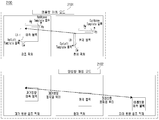
- FIG. 8 is a diagram for describing a method of deriving a temporal candidate among candidate motion information of SKIP, Merge, and AMVP modes.
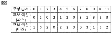
- FIG. 9 is a diagram for describing a method of deriving a combined bidirectional candidate mode among candidate motion information of SKIP and Merge modes.
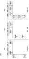
- FIG. 10 is a diagram illustrating motion estimation patterns used in a motion estimator in an image encoding apparatus or a DMVD motion estimator in an image encoding / decoding apparatus according to an embodiment.
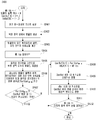
- 11 is a flowchart illustrating a method of encoding split information and prediction information.
- FIG. 12 is a flowchart schematically illustrating an image decoding apparatus.
- FIG. 13 is a diagram for describing a block divider of an image decoding apparatus.
- FIG. 14 is a diagram for describing a predictor of an image decoding apparatus.
- 15 is a flowchart illustrating a method of decoding split information and prediction information.
- FIG. 16 is a diagram for describing a block partitioner of an image encoding apparatus, according to an embodiment of the present invention.
- FIG. 17 is a diagram for describing a block partitioner of an image decoding apparatus, according to an exemplary embodiment.
- FIG. 18 is a diagram for describing a prediction unit of an image encoding apparatus, according to an embodiment of the present invention.
- 19 is a diagram for describing a prediction unit of an image decoding apparatus, according to an embodiment of the present invention.
- FIG. 20 is a diagram for describing a DMVD motion estimation unit of a prediction unit in an image encoding / decoding apparatus according to an embodiment of the present invention.
- 21 is a diagram for explaining a DMVD mode according to an embodiment of the present invention.
- FIG. 22 is a diagram for describing a method of determining a template block in a reconstruction area in a DMVD mode according to an embodiment of the present invention.
- FIG. 23 is a diagram for describing a method of searching for a partition motion boundary point of a block according to an embodiment of the present invention.
- FIG. 24 is a diagram for describing a speedup algorithm for searching for a motion boundary point of FIG. 22.
- FIG. 25 is a diagram for explaining a DMVD initial motion information search unit in a prediction unit in an image encoding / decoding apparatus according to an embodiment of the present invention.
- FIG. 26 is a diagram for describing a method of calculating a line cost value in the speedup algorithm of FIG. 23.
- FIG. 27 is a diagram for explaining an example of a block divided into two or four divided based on one or two divided motion boundary points of a block according to an embodiment of the present invention.
- FIG. 28 is a diagram illustrating a method of searching for motion information using only a partial region adjacent to the current block as a template in the reconstructed region based on the divided motion boundary points of FIGS. 23 and 24.
- FIG. 29 is a diagram illustrating a method of searching for motion information using the entire area adjacent to the current block as a template in the reconstruction area based on the divided motion boundary points of FIGS. 23 and 24.
- FIG. 30 is a flowchart illustrating a method of encoding split information and prediction information according to an embodiment of the present invention.
- 31 is a flowchart illustrating a method of decoding split information and prediction information according to an embodiment of the present invention.
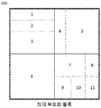
- FIG. 32 shows an example of partitioning a coding block according to an embodiment of the present invention.
- FIG 33 is a diagram for explaining a DMVD motion estimation unit of a prediction unit in an image encoding / decoding apparatus according to an embodiment of the present invention.
- 34 is a flowchart illustrating a method of determining a slope of a motion boundary line according to an embodiment of the present invention.
- FIG. 35 is a diagram for describing a method of determining a slope of a motion boundary line and dividing a current block in the motion boundary search area of FIG. 34.
- 36 is a diagram for describing a filtering method when dividing a current block straight line according to an embodiment of the present invention.
- FIG. 37 is a diagram for describing a filtering method when dividing a current block diagonal according to an embodiment of the present invention.
- 38 is a flowchart illustrating a method of encoding prediction information according to an embodiment of the present invention.
- 39 is a flowchart illustrating a method of decoding prediction information according to an embodiment of the present invention.
- FIG. 40 illustrates a method of performing intra prediction in a prediction unit of an image encoding / decoding apparatus according to an embodiment to which the present invention is applied.
- FIG. 41 is a view illustrating an intra prediction method in units of sub blocks according to an embodiment to which the present invention is applied.
- FIG. 42 illustrates a prediction method based on cross-component reference as an embodiment to which the present invention is applied.
- FIG. 43 is a view illustrating a method of determining delta motion information according to an embodiment to which the present invention is applied.
- the image encoding / decoding method and apparatus of the present invention determine reference information specifying a position of a reference region used for prediction of a current block, and based on the reference information, a pre-restored region spatially adjacent to the current block.
- a reference region may be determined, and the current block may be predicted based on the reference region.
- the reference region is determined as one of a plurality of candidate regions, and the plurality of candidate regions are at least one of a first candidate region, a second candidate region, or a third candidate region. It may include.
- the first candidate region includes an upper neighboring region of the current block
- the second candidate region includes a left neighboring region of the current block.
- the third candidate area may include the top and left neighboring areas of the current block.
- the first candidate region may further include a partial region of the upper right neighboring region of the current block.
- the second candidate region may further include a partial region of a lower left neighboring region of the current block.
- the video encoding / decoding method and apparatus of the present invention divide the current block into a plurality of subblocks based on coding information of the current block, and sequentially reconstruct the plurality of subblocks based on a predetermined priority. Can be.
- the coding information may include first information indicating whether the current block is divided.
- the coding information may further include second information indicating a division direction of the current block.
- the current block may be divided into a horizontal direction or a vertical direction based on the second information.
- the video encoding / decoding method and apparatus of the present invention may derive a partition boundary point of a block using a block partitioning method using a motion boundary point in a reconstruction area around a current block.
- the video encoding / decoding method and apparatus of the present invention determine initial motion information of a current block, determine delta motion information of the current block, and improve initial motion information of the current block by using the delta motion information.
- the motion compensation of the current block may be performed using the improved motion information.
- the determining of the delta motion information may include determining a search area for improving the motion information and generating a sum of absolute difference (SAD) list from the search area.
- the delta motion information may be updated based on the SAD candidate of the SAD list.
- the SAD list may specify SAD candidates for each search position in the search area.
- the search area includes an area extended by N sample lines based on a boundary of a reference block, wherein the reference block is based on initial motion information of the current block. It may be an area indicated.
- the SAD candidate may be determined as a SAD value between the L0 block and the L1 block, and the SAD value may be calculated based on some samples in the L0 and L1 blocks.
- the position of the L0 block is determined based on a position and a predetermined offset of the L0 reference block of the current block, wherein the offset is a non-directional offset or a directional offset. It may include at least one of.
- updating of the delta motion information is performed based on a comparison result between a reference SAD candidate and a predetermined threshold value, and the reference SAD candidate is set to the non-directional offset. It may mean a corresponding SAD candidate.
- the reference SAD candidate when the reference SAD candidate is greater than or equal to the threshold, a SAD candidate having a minimum value among the SAD candidates included in the SAD list is identified, and the SAD candidate is identified.
- the delta motion information can be updated based on the corresponding offset.
- the delta motion information is based on a parameter calculated using all or part of the SAD candidates included in the SAD list. Can be updated.
- the improvement of the initial motion information may be performed in units of sub-blocks in consideration of the size of the current block.
- the improvement of the initial motion information may include at least one of a size of the current block, a distance between a current picture and a reference picture, an inter prediction mode, a prediction direction, or a resolution of motion information. It may optionally be carried out in consideration.
- first and second may be used to describe various components, but the components should not be limited by the terms. The terms are used only for the purpose of distinguishing one component from another.
- each component shown in the embodiments of the present invention are shown independently to represent different characteristic functions, and do not mean that each component is composed of separate hardware or one software unit. That is, each component is described by listing each component for convenience of description, and at least two of the components may be combined to form one component, or one component may be divided into a plurality of components to perform a function. The integrated and separated embodiments of each of these components are also included within the scope of the present invention without departing from the spirit of the invention.
- An image encoding apparatus is a device for encoding an image, and includes a block divider, a predictor, a transformer, a quantizer, an entropy encoder, an inverse quantizer, an inverse transformer, an adder, an in-loop filter, a memory, and a subtractor. can do.
- the block dividing unit 101 divides the block to be encoded with the maximum size (hereinafter referred to as the maximum coding block) from the block to be encoded with the minimum size (hereinafter referred to as the minimum coding block).
- the maximum coding block is a splitting that exactly divides the current coding block.
- Binary-tree splitting is a splitting which splits a coding block exactly in the horizontal direction or the vertical direction.
- partitioning methods there may be various partitioning methods.
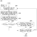
- FIG. 2 illustrates an operation flow of a block divider in a video encoding apparatus.
- a division method is selected among the QT division 201 or the BT division 203.
- QT splitting is performed, the upper depth block is divided into quarters 202 to generate a lower depth block to determine the current block.
- the BT division is made, the upper depth block is divided into two (204) to generate the lower depth block to determine the current block.
- the prediction unit 102 generates a prediction block by using pixels in a neighboring pixel of a block to be currently predicted (hereinafter, referred to as a prediction block) from a current original block or pixels in a reference picture that has been previously encoded / decoded.
- a prediction block In the prediction block, one or more prediction blocks may be generated in the coding block.
- the prediction technique of the video signal is largely composed of intra prediction and inter prediction.
- the intra prediction is a method of generating a prediction block by using neighboring pixels of the current block, and the inter prediction is already encoded / decoded.
- the prediction block is generated by finding a block most similar to the current block in the finished reference picture. Thereafter, the residual block obtained by subtracting the original block and the prediction block is determined by using various techniques such as rate-distortion optimization (RDO) to determine the optimal prediction mode of the prediction block.
- RDO cost calculation is the same as Equation 1.
- D, R and J are deterioration due to quantization, compression stream rate and RD cost, respectively
- ⁇ is an encoding mode
- ⁇ is a Lagrangian multiplier, which is a scale correction coefficient for matching a unit between an error amount and a bit amount. use.
- J when the mode is applied that is, the RD-cost value should be smaller than that when applying the other mode.
- FIG. 3 is a flowchart illustrating a flow in a predicting unit of a video encoding apparatus.
- the optimal intra prediction mode for each prediction mode is determined 302 by using the RD-cost value, and a prediction block is generated.
- the RD-cost value is calculated for the SKIP mode, the merge mode, and the AMVP mode.
- the merge candidate search unit 304 configures a SKIP mode and a candidate motion information set for the merge mode. Of the candidate motion information sets, optimal motion information is determined using the RD-cost value (305).
- the AMVP candidate searcher 306 configures a candidate motion information set for the AMVP mode. Motion estimation is performed using the candidate motion information sets (307), and optimal motion information is determined. Motion compensation is performed using the optimal motion information determined in each mode (308) to generate a prediction block.
- a motion estimation start point is determined in the reconstructed picture using candidate motion information in the AMVP mode (401).
- the start point of the motion estimation may be determined without using the AMVP candidate motion information (that is, this information means the Motion Vector Predictor), and the motion estimation may be started at a predetermined start point.
- a search maximum / minimum precision (N, M) of the motion vector for motion estimation is determined (402), a motion estimation pattern at the current estimation precision N is determined, and motion estimation is performed (403).
- the motion estimation pattern refers to FIG. 10.
- Figure 10 shows an example of the four motion estimation patterns.
- the pixel point marked with R means the pixel point currently estimated.
- a pixel point marked S1 refers to a pixel point estimated by one step of each pattern among adjacent pixel points based on the R pixel.
- the current motion estimation precision N is refined (404). If the refined precision N is smaller than the minimum estimated precision M, the optimal motion information up to the current precision is determined as the optimal motion information of the current block, and the flow is terminated. Otherwise, the flow returns to step 403 to repeat the above process.
- the above-described inter prediction may be composed of three modes (SKIP mode, merge mode, AMVP mode).
- Each prediction mode may obtain a prediction block of the current block by using motion information (prediction direction information, reference picture information, and motion vector), and there may be an additional prediction mode using motion information.
- the SKIP mode determines optimal prediction information by using motion information of an area which has already been restored.
- a motion information candidate group is configured to generate a prediction block using the candidate having the least RD-cost value as the prediction information, and the method of configuring the motion information candidate group is described in the MERGE mode described below. Since it is the same as the method of forming a motion information candidate group, it abbreviate
- the MERGE mode is the same as the SKIP mode in that the optimal prediction information is determined by using motion information of an area already restored.
- the SKIP mode differs in that the motion information for the prediction error is zero from the motion information candidate group, and the MERGE mode searches for the motion information candidate group with the non-zero prediction error in the motion information candidate group.
- a motion information candidate group is configured in the reconstructed region, and a prediction block is generated using the candidate having the least RD-cost value as the prediction information among the candidate groups.
- the maximum number of motion information candidate groups may be equally determined by the video encoding apparatus and the video decoding apparatus, and may be transmitted from an upper header of a block such as an upper header (an upper header, a video parameter stage, a sequence parameter stage, a picture parameter stage, etc.) of the video encoding apparatus. The number information may be previously transmitted. Only when the spatial candidate block and the temporal candidate block are encoded in the inter prediction mode in the description of steps S501 and S502, motion information derived using the motion information is included in the motion information candidate group. In step S501, four candidates are selected from five spatial candidate blocks around the current block within the same picture.
- the position of the spatial candidates is described with reference to FIG. 7, and the positions of each candidates can be changed to any block in the reconstructed area.
- the spatial candidates are determined in the order of A 1 , A 2 , A 3 , A 4 , and A 5 in order to determine the motion information of the available spatial candidate blocks as spatial candidates. If there is overlapping motion information, only motion information of a candidate having a high priority is considered.
- one candidate is selected from two temporal candidate blocks.
- the position of the temporal candidates is described with reference to FIG. 7, and the positions of the candidates are determined based on the block at the same position as the current block position of the current picture within the collocated picture.
- the collocated picture can be set under the same condition in the image encoding apparatus and the image decoding apparatus in the reconstructed picture.
- Temporal candidates are determined in the order of B 1 , B 2 blocks first to determine the motion information of the available candidate block as a temporal candidate. See FIG. 8 for a method of determining motion information of a temporal candidate.
- the motion information of candidate blocks B 1 and B 2 in a collocated picture indicates a prediction block in reference picture B.
- FIG. (However, reference pictures of each candidate block may be different from each other. In the present description, all of them are referred to as reference picture B.)
- the corresponding motion vector is compared with the distance between the collocated picture and the reference picture B, and the distance between the current picture and the reference picture A. By calculating the ratio, the motion vector of the candidate block is scaled by the corresponding ratio to determine the motion vector of the temporal candidate motion information.
- Equation 2 means a scaling equation.
- MV is a motion vector of temporal candidate block motion information
- MV scale is a scaled motion vector
- TB is a temporal distance between a collocated picture and a reference picture B
- TD is a temporal distance between a current picture and a reference picture A.
- the reference picture A and the reference picture B may be the same reference picture.
- the scaled motion vector is determined as the motion vector of the temporal candidate
- the reference picture information of the temporal candidate motion information is determined as the reference picture of the current picture to derive the motion information of the temporal candidate.
- Step S503 is performed only when the maximum number of motion information candidate groups is not satisfied in steps S501 and S502, and a new two-way motion information candidate group is added by combining the motion information candidates derived in the previous step.
- the bidirectional motion information candidate is to take motion information of past or future directions derived one by one and combine them into new candidates.
- the table of FIG. 9 shows the priority of the bidirectional motion information candidate combination. In addition to the combination of the table can be further combinations, this table shows one example. If the maximum number of motion information candidate groups is not satisfied even using the bidirectional motion information candidate, step S504 is performed. In step S504, the motion vector of the motion information candidate is fixed as a zero motion vector, and the maximum number of motion information candidate groups is filled by varying the reference picture according to the prediction direction.
- the AMVP mode determines the optimal motion information through motion estimation for each reference picture according to the prediction direction.
- the prediction direction may be a unidirectional direction using only one of the past / future directions, or may be a bidirectional direction using both the past and future directions.
- the prediction block is generated by performing motion compensation using the optimal motion information determined through the motion estimation.
- a motion information candidate group for motion estimation is derived for each reference picture according to the prediction direction.
- the motion information candidate group is used as a starting point of motion estimation. 6 illustrates a method of deriving a motion information candidate group for motion estimation in AMVP mode.
- the maximum number of motion information candidate groups may be equally determined by the image encoding apparatus and the image decoding apparatus, or corresponding number information may be transmitted in the upper header of the image encoding apparatus. Only when the spatial candidate block and the temporal candidate block are encoded in the inter prediction mode in the description of steps S601 and S602, motion information derived using the motion information is included in the motion information candidate group.
- operation S601 unlike the description of operation S501 of FIG. 5, the number (2) derived as the spatial candidates may be different, and the priority for selecting the spatial candidates may also be different. The rest of the description is the same as that of step S501.
- Step S602 is the same as the description of step S502. In step S603, if there is duplicate motion information among candidates derived so far, it is removed.
- Step S604 is the same as the description of step S504.
- a motion information candidate having a minimum RD-cost value is selected as an optimal motion information candidate to obtain optimal motion information in the AMVP mode through a motion estimation process based on the motion information.
- the transform unit 103 generates a transform block by transforming the residual block that is a difference between the original block and the prediction block.
- the transform block is the smallest unit used for the transform and quantization process.
- the transform unit converts the residual signal into the frequency domain to generate a transform block having transform coefficients.
- various transformation techniques such as Discrete Cosine Transform (DCT) -based, Discrete Sine Transform (DST), and Karhunen Loeve Transform (KLT) can be used.
- DCT Discrete Cosine Transform
- DST Discrete Sine Transform
- KLT Karhunen Loeve Transform
- the residual signal is transformed into the frequency domain to generate a transform coefficient.
- a matrix operation is performed using a basis vector.
- the transform method can be mixed and used in the matrix operation.
- a discrete cosine transform may be used in the horizontal direction and a discrete sine transform in the vertical direction, depending on the prediction mode.
- the quantization unit 104 quantizes the transform block to generate a quantized transform block. That is, the quantization unit quantizes the transform coefficients of the transform block generated from the transform unit 103 to generate a quantized transform block having quantized transform coefficients.
- the quantization method dead zone uniform threshold quantization (DZUTQ) or a quantization weighted matrix (DZUTQ) may be used, but various quantization methods such as quantization improved therefrom may be used.
- the image encoding apparatus includes a transformer and a quantizer, but the transformer and the quantizer may be selectively included. That is, the apparatus for encoding an image may generate a transform block by transforming the residual block and not perform the quantization process, and may not only perform the quantization process without converting the residual block into frequency coefficients, or even convert and quantize the process. You may not do all of them. Even if some processes of the transform unit and the quantization unit are not performed or all processes are not performed in the image encoding apparatus, a block entering the input of the entropy encoding unit is generally referred to as a “quantized transform block”.
- the entropy encoder 105 encodes the quantized transform block and outputs a bitstream. That is, the entropy encoder encodes the coefficients of the quantized transform block output from the quantizer using various encoding techniques such as entropy encoding, and additional information necessary to decode the block in an image decoding apparatus to be described later (for example, a bitstream including information about a prediction mode (information about the prediction mode may include motion information or intra prediction mode information determined by the prediction unit), a quantization coefficient, and the like is generated and output.
- the inverse quantization unit 106 inversely performs a quantization technique used in quantization on the quantized transform block to restore the inverse quantization transform block.
- the inverse transform unit 107 inversely transforms an inverse quantized transform block using the same method used in the transform, and restores the residual block.
- the inverse transform is performed by inversely performing the transform technique used in the transform unit.
- the inverse quantization unit and the inverse transform unit may perform inverse quantization and inverse transformation by using the quantization method and the transformation method used in the quantization unit and the transform unit inversely.
- the inverse quantization unit and the inverse transformer may also be omitted without performing inverse transformation and inverse quantization or not included in the image encoding apparatus.
- the adder 108 reconstructs the current block by adding the residual signal generated by the inverse transformer and the prediction block generated through the prediction.
- the filter unit 109 is a process for additionally filtering the entire picture after all the blocks in the current picture are reconstructed, such as deblocking filtering and sample adaptive offset (SAO).
- Deblocking filtering refers to an operation of reducing block distortion generated by encoding an image in units of blocks.
- Sample Adaptive Offset (SAO) is a method of minimizing a difference between a reconstructed image and an original image by subtracting or adding a specific value to a reconstructed pixel. Say work.
- the memory 110 adds the residual signal generated by the inverse transform unit and the prediction block generated through the prediction, and then stores the restored current block that is further filtered by the in-loop filter unit, and stores the next block or the next picture. Can be used to predict
- the subtraction unit 111 generates a residual block by subtracting the prediction block from the current original block.
- step S1101 information indicating whether a current coding block is divided is encoded.
- step S1102 it is determined whether the current coding block is divided. If the current coding block is split in step S1102, in step S1103, which of the QT split, BT horizontal split, and BT vertical split is used is encoded.
- step S1104 the current coding block is divided according to the division method.
- step S1105 the process moves to the first sub-coding block divided within the current coding block, and then returns to step S1101. If the current coding block is not divided in step S1102, operation information of the SKIP mode is encoded in step S1106.
- step S1107 it is determined whether the SKIP mode is operating. If the SKIP mode operates in step S1107, Merge candidate index information for the SKIP mode is encoded in step S1113. After that, the flow proceeds to step S1123. The description will be described in detail below. If the SKIP mode does not operate in step S1107, the prediction mode is encoded in step S1108. In step S1109, it is determined whether the prediction mode is inter prediction or intra prediction. If the prediction mode is the intra prediction mode in step S1109, the intra prediction mode information is encoded in step S1110, and the flow advances to step S1123. The description will be described in detail below.
- step S1112 If the prediction mode is the inter prediction mode in operation S1109, operation information of the merge mode is encoded in operation S1111.
- step S1112 it is determined whether the merge mode is operating. If the merge mode is operated in step S1112, the process proceeds to step S1113 to encode Merge candidate index information for the merge mode. If the merge mode does not operate in step S1112, the prediction direction is encoded in step S1114.
- the prediction direction may be one of a past direction, a future direction, and a bidirectional direction.
- step S1115 it is determined whether the prediction direction is the future direction. If the prediction direction is not the future direction in step S1115, the reference picture index information of the past direction is encoded in step S1116.
- step S1117 MVD (Motion Vector Difference) information of the past direction is encoded.
- step S1118 MVP (Motion Vector Predictor) information of the past direction is encoded.
- step S1115 when the prediction direction is a future direction or a bidirectional direction, or after step S1118, it is determined whether the prediction direction is the past direction in step S1119. If the prediction direction is not the past direction in step S1119, the future reference picture index information is encoded in step S1120.
- step S1121 MVD information of a future direction is encoded.
- step S1122 MVP information of the future direction is encoded.
- step S1119 when the prediction direction is the past direction or the bidirectional direction, or in step S1122, it is determined in step S1123 whether the encoding of all the sub-coded blocks is finished.
- the process of this step is performed even after step S1113 is completed. If it is finished, the flowchart ends. If not, the flow moves from the current sub coding block to the next sub coding block in step S1124, and the above-described process is repeated from step S1101.
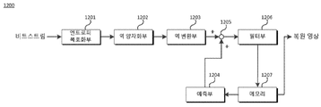
- the image decoding apparatus is an apparatus for decoding an image, and may include a block entropy decoder, an inverse quantizer, an inverse transformer, a predictor, an adder, an in-loop filter, and a memory.
- a coding block in a video encoding apparatus is called a decoding block in a video decoding apparatus.
- the entropy decoder 1201 interprets the bitstream received from the image encoding apparatus and reads various information and quantized transform coefficients necessary for decoding the corresponding block.
- the inverse quantizer 1202 inversely performs a quantization technique used in quantization on the quantization coefficients decoded by the entropy decoder to restore an inverse quantized block having inverse quantized coefficients.
- the inverse transform unit 1203 inversely transforms an inverse quantized transform block by using the same method as the transform method and restores a residual block having a differential signal.
- the inverse transform is performed by inversely performing a transform technique used in the transform unit. .
- the prediction unit 1204 generates a prediction block using the prediction mode information decoded by the entropy decoding unit, which uses the same method as the prediction method performed by the prediction unit of the image encoding apparatus.
- the adder 1205 reconstructs the current block by adding the residual signal reconstructed by the inverse transformer and the prediction block generated through the prediction.
- the filter unit 1206 After reconstructing all the blocks in the current picture, the filter unit 1206 performs additional filtering on the entire picture, and includes deblocking filtering and sample adaptive offset (SAO). Same as described in the in-loop filter section.
- the memory 1207 adds the residual signal generated by the inverse transform unit and the prediction block generated through the prediction, and then stores the restored current block that has been further filtered by the in-loop filter unit, and stores the next block or the next picture. Can be used to predict
- the split information is extracted from the higher depth block layer (1301), and the split method is selected from the QT split 1302 or the BT split 1304.
- QT division the upper depth block is divided into 1303 to generate a lower depth block to determine the current block.
- BT splitting the upper depth block is divided into two portions 1305 to generate a lower depth block to determine the current block.
- the optimal intra prediction mode information is determined 1401, and intra prediction is performed 1402 to generate a prediction block.
- the prediction mode is inter prediction, an optimal prediction mode among SKIP, Merge, and AMVP modes is determined 1403.
- the merge candidate searcher 1404 configures the SKIP mode and a candidate motion information set for the merge mode.
- optimal motion information is determined 1405.
- the AMVP candidate searcher 1406 configures a candidate motion information set for the AMVP mode.
- optimal motion information is determined using the transmitted MVP information (1407). Thereafter, motion compensation is performed using the optimal motion information determined in each mode (1408) to generate a prediction block.
- step S1501 information indicating whether or not the current decoding block is divided is decoded.
- step S1502 it is determined whether the current decoding block is divided. If the current decoding block is divided in step S1502, in step S1503, which of the QT splitting, BT horizontal splitting, and BT vertical splitting is used is decoded.
- step S1504 the current decoding block is divided according to the partitioning method.
- step S1505 after moving to the first sub decoding block divided in the current decoding block, the process returns to step S1501. If the current decoding block is not divided in step S1502, operation information of the SKIP mode is decoded in step S1506.
- step S1507 it is determined whether the SKIP mode is operating. If the SKIP mode is operated in step S1507, Merge candidate index information for the SKIP mode is decoded in step S1513. After that, the flow proceeds to step S1523. The description will be described in detail below. If the SKIP mode does not operate in step S1507, the prediction mode is decoded in step S1508. In step S1509 it is determined whether the prediction mode is inter prediction or intra prediction. If the prediction mode is the intra prediction mode in step S1509, the intra prediction mode information is decoded in step S1510, and the flow advances to step S1523. The description will be described in detail below.
- step S1512 it is determined whether the merge mode is operating. If the merge mode is operated in step S1512, the process proceeds to step S1513 to decode the merge candidate index information for the merge mode. If the merge mode does not operate in step S1512, the prediction direction is decoded in step S1514.
- the prediction direction may be one of a past direction, a future direction, and a bidirectional direction.
- step S1515 it is determined whether the prediction direction is the future direction. If the prediction direction is not the future direction in step S1515, the reference picture index information of the past direction is decoded in step S1516.
- step S1517 MVD (Motion Vector Difference) information in the past direction is decoded.
- step S1518 the MVP (Motion Vector Predictor) information of the past direction is decoded.
- step S1515 if the prediction direction is a future direction or a bidirectional direction, or after step S1518, it is determined in step S1519 whether the prediction direction is a past direction. If the prediction direction is not the past direction in step S1519, the future direction reference picture index information is decoded in step S1520.
- step S1521 MVD information in the future direction is decoded.
- step S1522 the MVP information of the future direction is decoded.
- step S1519 when the prediction direction is in the past or in both directions, or after step S1522, it is determined in step S1523 whether decoding of all sub decoding blocks has been completed. Here, the process of this step is performed even after step S1513 is completed. If it is finished, the flowchart ends. If not, the flow moves from the current sub decoding block to the next sub decoding block in step S1524, and the above-described process is repeated from step S1501.
- a method of dividing a current coded block by searching for a motion boundary point at a current coded block boundary by using surrounding motion information of the current coded block, and in each sub-coded block in DMVD (Decoder-side Motion Vector Derivation) mode It will be described how to predict using.
- 16 is a block splitter in an image encoding apparatus, according to an embodiment.
- steps 1601 to 1604 determine the current block through the same process as steps 201 to 204 of FIG. 2.
- the motion boundary point is searched for (1606).
- MT splitting refers to a method of searching for a motion boundary point in an upper depth block and dividing the block at the boundary point. The method for searching for the motion boundary is described in detail below.
- the upper depth block is divided 1607 based on the detected motion boundary to determine the current block. The method of dividing the upper depth block is also described in detail below.
- the split information is extracted 1701 from the upper depth block.
- the partition information determines whether the QT partition, the BT partition, or the MT partition.
- Steps 1702 to 1705 determine the current block through the same steps as steps 1302 to 1305 of FIG. 13.
- the motion boundary point is searched for (1707). The method for searching for the motion boundary is described in detail below.
- the upper depth block is divided 1708 based on the found motion boundary point to determine the current block. The method of dividing the upper depth block is also described in detail below.
- QT, BT, and MT splitting may be applied to and used from the largest coding block to the smallest coding block.
- splitting may be performed using only some splitting methods according to the size and depth of the coding block.
- the maximum coding block size is 64x64 and the minimum coding block size is 4x4 will be described.
- the coded block size for QT splitting is 64x64 to 16x16
- the maximum coded block size for BT and MT splitting is 16x16 and the splittable depth is 3, referring to FIG. 32.
- the solid line means QT division
- the dotted line means BT division
- the dotted line combination line means MT division.
- coding block division may be performed as shown in FIG. 32.
- the current coding block may be split into odd-numbered coding blocks.
- BT splitting may be performed on the 9x4 and 8x4 coded blocks to perform coding.
- the maximum size, the minimum size, and the segmentable depth of the coding block for each division method may be transmitted in the upper header.
- the prediction block may be generated using the optimal intra prediction mode determined through steps 1801 to 1802, or the motion compensation 1810 may be generated using the optimal motion information determined through steps 1803 to 1807 and the prediction block may be generated.
- inter prediction there is a method of determining motion information using a DMVD mode.
- initial motion information is determined using motion information of a reconstruction region (1808).
- the motion estimation is performed using the determined initial motion information (1809) to determine the optimal motion information, and the motion compensation 1810 is performed to generate a prediction block.
- Processes 1901 to 1907 perform the same process as process 1401 to 1407 of FIG. 14.
- the prediction block may be generated using the optimal intra prediction mode determined through steps 1901 to 1902, or the motion compensation 1910 may be performed using the optimal motion information determined through steps 1903 to 1907 to generate the prediction block.
- inter prediction there is a method of determining motion information using a DMVD mode.
- initial motion information is determined using the motion information of the reconstructed region (1908).
- the motion estimation is performed using the determined initial motion information (1909) to determine the optimal motion information, and the motion compensation 1910 is performed to generate a prediction block.
- the optimal motion information obtained through the motion estimation using the template block may be applied to the current prediction block by the DMVD motion estimation units 1809 and 1909 of FIGS. 18 and 19, the reconstructed motion information in the template block may be used as it is. It may also be formed of optimal motion information.
- the current coding block is MT-divided from the higher depth block, only the DMVD mode may be used as the prediction mode of the current coding block.
- the optimal motion information derived in the DMVD mode may be used as a candidate of the AMVP mode.
- the DMVD mode includes a mode using a template (hereinafter referred to as a template matching mode) and a mode not using a template (hereinafter referred to as a "bidirectional matching mode").
- a template matching mode a mode using a template
- a mode not using a template hereinafter referred to as a "bidirectional matching mode”
- the motion vector in each direction that minimizes the difference between the prediction block in the past direction and the future direction is determined as the optimum motion information (2003).
- 2102 of FIG. 21 illustrates a method of generating a prediction block of a current block as an average of two prediction blocks in both directions after linearly generating motion vectors in the past and future directions of a current block in a bidirectional matching mode.
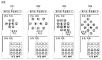
- the template block is determined (2005) in the reconstruction area around the current block.
- the template block may be set as shown in the example of 2201 to 2203 of FIG. 22.
- FIG. 2201 determines the template block at the lower left (Template A), the upper left (Template B), the upper left (Template C), and the upper right (Template D) of the current block.
- the size and shape of each template block can vary.
- Figure 2202 shows that the template block can be determined at the lower left (Template A), upper left (Template B), upper left (Template C), and upper right (Template D) of the current block, similar to the method shown in Figure 2201. The difference is different in that both the left and top restoration areas are used.
- Figure 2203 is a method for generating a template block considering the template block generation method of Figure 2201, 2202 at the same time.
- the template block may be generated in the reconstruction area around the current block in various ways, such as by using the reconstruction area on the left and top adjacent to the current block as one template block.
- information indicating the shape and size of the template block may be transmitted and used by the video encoding apparatus.
- the motion information most suitable for each template block is estimated, and the motion information most suitable for the current block among the corresponding motion information is obtained.
- the search determines the optimal motion information.
- the estimation pattern may select an arbitrary pattern among the four motion estimation pattern methods illustrated in FIG. 10 and perform motion estimation by the corresponding method.
- the cost value of motion estimation means the sum of the amount of prediction error and the virtual bit amount of motion information.
- the prediction error may be obtained through various calculation methods such as sum of absolute difference (SAD), sum of absolute hadamard trance form difference (SATD), and sum of square difference (SSD). Equations (3), (4), and (5) are equations showing calculation methods of SAD, SATD, and SSD, respectively.
- i, j are pixel positions Template (i, j) is a pixel of a template block, and PredBlk (i, j) is a pixel of a prediction block.
- the HT () function of Equation 4 means a function value obtained by Hadamard transforming the difference block of the template block and the prediction block.
- the virtual bit amount of the motion information is not actually transmitted information, but the virtual bit amount of the motion information which is equally expected in the video encoding apparatus and the video decoding apparatus is calculated. For example, the magnitude of the difference vector between the motion vector of the initial motion information and the motion vector in the motion information under current motion estimation may be calculated to determine the virtual bit amount.
- the motion information virtual bit amount may be calculated using the bit amount of the reference picture information.
- FIG. 21 illustrates a prediction block of a template block most similar to a template block when the left and upper reconstruction areas adjacent to the current block are one template block, and then the block adjacent to the template block is selected as a template block. It shows how to determine the prediction block.
- FIG. 23 is a flowchart illustrating a method of searching for a motion boundary point according to an embodiment.
- the flowchart is performed in the process of searching for motion boundary points 1606 and 1707 of the block partitioner in the image encoding / decoding apparatus, according to an embodiment.
- the index information (hereinafter referred to as 'MB Idx') of the motion boundary point is initialized to -1 and the number of template blocks is initialized to 2 NumOfMB .
- NumOfMB is the number of motion boundary points. In the present embodiment, the number of motion boundary points is limited to a maximum of two, but more than this may be selected.
- the CostBuf [N] buffer initializes all arguments to infinity and the IdxBuf [N] buffer initializes each argument to -1. Thereafter, the initial motion information list is determined (S2301). A method of determining the initial motion information list is described with reference to FIG. 25.
- the index in the table of FIG. 25 indicates initial motion information priority.
- Initial motion information such as candidate motion information of AMVP mode, candidate motion information of Merge mode, motion information of sub-blocks in the reconstruction area in the upper, left, upper left, upper right, lower left direction around the current block, and zero motion information.
- various motion information candidates may be used by using reconstruction information.
- the MB Idx is updated by increasing the MB Idx by 1 (S2302).
- a template block is generated in the reconstruction area based on the current motion boundary point (S2303), and the optimum motion information of each template block is searched (S2304). See FIGS. 28 and 29 for details of the steps S2303 and S2304.
- 28 and 29 are diagrams illustrating a method of determining a template block in a reconstruction area on the basis of a current motion boundary point and deriving optimal motion information for each template block.
- FIG. 28 only a partial restoration area is generated as a template block based on the movement boundary point.
- the prediction block most similar to the template A block is searched for in the reference picture, and the template B block is searched for as well.
- the template C block means a block in which the template A and B blocks are combined, and the block most similar to the template C block is searched for in the reference picture as well.
- FIG. 29 determines template A, B, and C blocks based on a motion boundary point in a reconstructed region of the left and upper regions adjacent to a current block, and searches a prediction picture most similar to each template block in a reference picture. .
- the split cost value at the current motion boundary point is calculated using the cost values (eg, SAD, SATD, SSD cost values, etc.) for the optimal motion information of each template block.
- the division cost value may be determined using various information.
- the first method of determining the split cost value is to determine the sum of the cost value of the template A block and the cost value of the template B as the split cost value. At this time, the cost value of the template C block is not used. See Equation 6 for a second method of determining the split cost value.
- Equation 6 calculates the rate of change of the sum of the cost values of the template A and B blocks with respect to the cost value of the template C block.
- CostBuf [N-1 ] If it is determined whether the split cost value at the current motion boundary is smaller than at least one element value in the CostBuf buffer (S2306), and if the current split cost value is smaller than at least one element value in the Costbuf buffer, CostBuf [N-1 ]
- the current division cost value is stored in the buffer and the current MB Idx is stored in the IdxBuf [N-1] buffer (S2307).
- the element values in the CostBuf buffer are sorted in ascending order (S2308), and the element values in the IdxBuf buffer are sorted in the same manner according to the CostBuf buffer sorting sequence (S2309).
- CostBuf buffer when N is 4, 4 elements of CostBuf buffer are stored as ⁇ 100, 200, 150, 180 ⁇ , and 4 elements of IdxBuf buffer are stored as ⁇ 0, 3, 2, 8 ⁇ .
- CostBufs are ordered ⁇ 100, 150, 180, 200 ⁇
- IdxBufs are ordered ⁇ 0, 2, 8, 3 ⁇ in the same sorting method as the CostBuf buffer. If the current split cost value is greater than any element in the Costbuf buffer, or after step S2309, it is determined whether the current MB Idx is the last search candidate split boundary point (S2310). If the current motion boundary point was the last search candidate division boundary point, the flowchart ends, otherwise, the flow returns to step S2302 to update the MB Idx and repeat the above-described process.
- FIG. 24 illustrates a method of searching for a motion boundary according to an embodiment, which is a speeding algorithm of the flowchart of FIG. 23.
- the flowchart may be performed in the process of searching for motion boundary points 1606 and 1707 of the block division unit in the image encoding / decoding apparatus, or may be performed in the DMVD motion estimation unit of the prediction unit.
- the initial initial information is the same as the initial information of FIG.
- the method of setting the initial motion information list (S2401) is the same as the description of step S2301 of FIG.
- Some non-adjacent regions of the left, upper, and left upper, upper, and lower left regions adjacent to the current block in the restoration region are determined as one template block (S2402).
- the cost values of all the motion information are calculated and stored in line units within the motion estimation range using the initial motion information (S2403).
- a cost value is stored in line units.
- FIG. 26 illustrates a method of storing cost values in units of lines in a region determined as a template block in a restoration region.
- H-Cost 0 to H-Cost H-1 means the cost value corresponding to each motion information on the left side of the current block in line units
- W-Cost 0 to W-Cost W-1 means the current block.
- the cost value corresponding to each motion information is stored in line units.
- the process of updating the MB Idx (S2404) is the same as the description of step S2302 of FIG. 23.
- the template block is regenerated in the reconstruction area based on the current movement boundary point (S2405).
- the method of regenerating the template block is the same as that described in step S2303 of FIG. Since the line unit cost value for the optimal motion information of the regenerated template block was calculated in operation S2403, the segmentation cost value at the current motion boundary point is calculated using the line unit cost value.
- the method of calculating the split cost value is the same as that described in step S2305 of FIG. 3.
- Steps S2407 to S2410 are the same as the descriptions of steps S2306 to S2309 in FIG. 23. If the current MB Idx is not the last search candidate division boundary point in step S2411, the process returns to step S2404 to repeat the above-described process.
- the upper depth block may be divided at one or two motion boundary points.
- the block is partitioned at one motion boundary point; otherwise, if the upper two segmentation cost values are similar, at the two motion boundary points Can be divided.
- the encoding / decoding information in the image encoding / decoding apparatus to be described later does not include the content of transmitting the motion boundary point information.
- the optimal MB Idx may be directly transmitted among all the MB Idxs, after determining M candidate MB Idxs, a motion boundary point at which the RD-cost value is optimal among the M MB Idxs may be transmitted.
- FIG. 27 illustrates a method of dividing an upper depth block (current block) according to the number of motion boundary points. Since MB Idx is known in the order of the smallest split cost values through the steps 23 and 24, when only one motion boundary point is used, the motion boundary point corresponding to the MB Idx having the smallest split cost value is determined as the split boundary point as shown in 2701.
- the current block is divided into lower depth blocks (prediction blocks) A and B.
- the lower depth block B may perform motion estimation again using the lower regions of the template A block and the lower depth block A to derive optimal motion information. If two moving boundary points are used and at least one MB Idx in the upper and left direction exists in the IdxBuf array of FIGS.
- Two moving boundary points corresponding to MB Idx having the smallest splitting value in the boundary point and left direction are determined as splitting boundary points, and the current block is divided into lower depth blocks A, B, C, and D.
- the lower depth block B can derive the optimal motion information by performing motion estimation again using the right region of the template D block and the lower depth block A
- the lower depth block C is the lower depth block C.
- the motion estimation is performed again using the lower region of the template A block and the lower depth block A to derive the optimal motion information.
- the motion estimation may be performed again using the right region of the lower depth block C and the lower region of the lower depth block B to derive optimal motion information.
- Prediction block A may be obtained through the above-described DMVD motion estimation using template B and C blocks as one template block. It can be obtained through the above-described DMVD motion estimation using the prediction block B corresponding template A block as one template block.
- the prediction block B is the restoration area template C 'block and the template A block of the prediction block A. May be obtained through DMVD motion estimation using one template block. If two moving boundary points are used and at least one MB Idx in the upper and left direction exists in the IdxBuf array of FIGS.
- Block A may be obtained through the above-described DMVD motion estimation using template B and C blocks as one template block.
- the prediction block B uses the template block D as one template block, the prediction block C as the template block A as one template block, and the prediction block D as the prediction block D and A block as one template block. Can be obtained through estimation.
- the prediction block B is a template block B and a template block D.
- the prediction block B is generated and then restored, and the prediction block C generates and then restores the prediction block C using the template A block and the template C 'block as one template block, and the prediction block D is the template D'. Create and restore the prediction block D using the block and template A 'block as one template block.
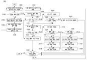
- FIG. 30 is a flowchart illustrating a flow of encoding some coding information by an entropy encoder in the image encoding apparatus.
- an exemplary method of encoding partition information and prediction information of a block will be described.
- information indicating whether a coding block is divided is encoded (S3001). It is determined whether or not the coding block is divided (S3002). If the division is true, information indicating whether the division is performed by QT division, BT division, or MT division is encoded (S3003). In this case, there is no additional encoding information when the MT boundary is fixed by using one or two motion boundary points, but when one or two motion boundary points are adaptively selected and used according to the characteristics of the current block.
- step S3004 it is determined whether the current coded block is a block divided by MT split (S3006). If the current coding block is not a block divided by MT partitioning, operation information of the SKIP mode is encoded (S3007).
- the operation of the SKIP mode is determined (S3008), and if the corresponding information is false, the prediction mode information is encoded (S3009).
- the prediction mode information is encoded (S3019).
- the intra prediction information is encoded (S3011), and the flow proceeds to step S3030.
- DMVD mode operation information is encoded (S3012).
- the template information is encoded (S3014).
- the template information is information for notifying which template of the template blocks in the reconstruction area is used to predict the current block.
- step S3030 If there is only one template block, the corresponding information may not be encoded. Thereafter, the process proceeds to step S3030, which will be described in detail later. If the current coding block is a block divided by MT partitioning in step S3006, the template information is encoded in step S3019, and then the flow proceeds to step S3030. The subsequent steps are likewise described in detail below. If the operation of the DMVD mode is false in step S3013, Merge candidate index information for the SKIP mode is encoded (S3020). If the prediction mode is the inter prediction mode in operation S3010, operation information of the merge mode is encoded (S3015).
- DMVD mode operation information is encoded (S3017).
- template information is encoded (S3019). If the information is false, Merge candidate index information for the merge mode is encoded (S3020). After the steps S3019 and S3020 are completed, the process proceeds to step S3030. The subsequent steps are likewise described in detail below. If the operation of the merge mode is false in step S3016, the prediction direction is encoded (S3021). The prediction direction may mean one of a past direction, a future direction, and a bidirectional direction. It is determined whether the prediction direction is the future direction (S3022).
- step S3025 If the prediction direction is not the future direction, reference picture index information in the past direction, MVD information in the past direction, and MVP information in the past direction are encoded (S3023, S3024, and S3025). After the prediction direction is the future direction or the step S3025 is finished, it is determined whether the prediction direction is the past direction (S3026). If the prediction direction is not the past direction, future reference picture index information, future MVD information, and future direction MVP information are encoded (S3027, S3028, and S3029). After the prediction direction is in the past or after step S3029, the process moves to step S3030. In this step, it is determined whether or not encoding of all sub-coding blocks is completed (S3030). If all sub coded blocks have been encoded, this flowchart ends. Otherwise, the flow returns to the next sub coded block (S3031) and then returns to step S3001 to repeat the above-described process.
- FIG. 31 is a flowchart illustrating a flow of decoding some coding information by an entropy decoder in an image decoding apparatus.
- a method of decoding encoding information of some coding information by an entropy encoder in the image encoding apparatus of FIG. 30 will be described.
- information indicating whether a decoding block is divided or not is decoded (S3101). It is determined whether to split the decoding block (S3102), and if the split is true, then information indicating whether the split is performed by QT splitting, BT splitting, or MT splitting is decoded (S3103).
- step S3104 the current decoding block is divided (S3104) according to the division method at the division boundary point and then moved to the first sub-decoding block (S3105). Thereafter, the process returns to step S3101 to repeat the above-described process. If the split is false in step S3102, it is determined whether the current decoding block is a block divided by the MT split (S3106).
- the operation information of the SKIP mode is decoded (S3107).
- the operation of the SKIP mode is determined (S3108). If the corresponding information is false, the prediction mode information is decoded (S3109).
- the prediction mode information is decoded (S3109).
- the intra prediction information is decoded (S3111), and then the operation proceeds to step S3130. The following will be described in detail below. If it is determined in step S3108 that the SKIP mode is operating, the DMVD mode operation information is decoded (S3112).
- step S3113 After determining whether to operate the DMVD mode (S3113), if the information is true, the template information is decoded (S3114). Thereafter, the process proceeds to step S3130, which will be described later in detail. If the current decoding block is a block divided by MT partitioning in step S3106, the template information is decrypted (S3119) and then the process proceeds to step S3130. The subsequent steps are likewise described in detail below. If the operation of the DMVD mode is false in step S3113, Merge candidate index information for the SKIP mode is decoded (S3120). If the prediction mode is the inter prediction mode in operation S3110, operation information of the merge mode is decoded (S3115).
- the DMVD mode operation information is decoded (S3117).
- the template information is decoded (S3119). If the information is false, the merge candidate index information for the merge mode is decoded (S3120). After the steps S3119 and S3120 are completed, the process proceeds to step S3130. The subsequent steps are likewise described in detail below. If the operation of the merge mode is false in step S3116, the prediction direction is decoded (S3121).
- the prediction direction may mean one of a past direction, a future direction, and a bidirectional direction.
- the prediction direction is the future direction (S3122). If the prediction direction is not the future direction, the past reference picture index information, the past direction MVD information, and the past direction MVP information are decoded (S3123, S3124, and S3125). After the prediction direction is the future direction or the step S3125 is finished, it is determined whether the prediction direction is the past direction (S3126). If the prediction direction is not the past direction, the future reference picture index information, the future MVD information, and the future direction MVP information are decoded (S3127, S3128, S3129). After the prediction direction is in the past or after step S3129, the process moves to step S3130.
- step S3130 it is determined whether or not decoding of all sub decoding blocks has been completed (S3130). If all sub-decoding blocks have been decoded, this flowchart ends. Otherwise, the flow returns to the next sub-decryption block (S3131) and then returns to step S3101 to repeat the above-described process.
- the DMVD mode includes a mode using a template (hereinafter referred to as a template matching mode) and a mode not using a template (hereinafter referred to as a "bidirectional matching mode").
- a template matching mode a mode using a template
- a mode not using a template hereinafter referred to as a "bidirectional matching mode"
- a motion vector in each direction that minimizes the difference between the prediction block in the past direction and the future direction is determined 3303 as the optimum motion information.
- 2102 of FIG. 21 illustrates a method of generating a prediction block of a current block as an average of two prediction blocks in both directions after linearly generating motion vectors in the past and future directions of a current block in a bidirectional matching mode.
- the template matching mode 3304
- the number of template blocks in the reconstruction area is determined.
- the reconstruction area on the left side and the upper side adjacent to the current block is determined as the template block, and motion estimation using the template block (3306)
- the optimal motion information is determined through. 2101 of FIG. 21 illustrates a method of searching for a prediction block of a template block most similar to a template block in a single template matching mode, and then determining a block adjacent to the template block as a prediction block of the current block.
- the estimation pattern may select an arbitrary pattern among the four motion estimation pattern methods illustrated in FIG. 10 and perform motion estimation by the corresponding method.
- the cost value of motion estimation means the sum of the amount of prediction error and the virtual bit amount of motion information.
- the prediction error may be obtained through various calculation methods such as sum of absolute difference (SAD), sum of absolute hadamard trance form difference (SATD), and sum of square difference (SSD). This is as described with reference to FIG. 20, and a detailed description thereof will be omitted.
- the template block When using the multi-template block (3307) (hereinafter, referred to as a "multi-template matching mode"), it is determined whether to use a plurality of template blocks in the reconstruction area or to generate a template block adaptively using a motion boundary point. do.
- the template block When used as a fixed template block (3308), the template block can be set as shown in the example of 2201 to 2203 of FIG. 2201 determines the template block at the lower left (Template A), the upper left (Template B), the upper left (Template C), and the upper right (Template D) of the current block.
- the size and shape of each template block can vary.
- Figure 2202 shows that the template block can be determined at the lower left (Template A), upper left (Template B), upper left (Template C), and upper right (Template D) of the current block, similar to the method shown in Figure 2201. The difference is different in that both the left and top restoration areas are used.
- Figure 2203 is a method for generating a template block considering the template block generation method of Figure 2201, 2202 at the same time.
- the template block may be generated in the reconstruction area around the current block in various ways, such as by using the reconstruction area on the left and top adjacent to the current block as one template block.
- information indicating the shape and size of the template block may be transmitted and used by the video encoding apparatus.
- the motion information most suitable for each template block is estimated, and the motion information most suitable for the current block among the corresponding motion information is obtained.
- the search determines the optimal motion information.
- the motion boundary point is first searched (3309).
- the motion boundary point search method is described in detail below.
- the optimal motion information for each template block is estimated (3310) through motion estimation for each template block divided based on the determined motion boundary point, and the optimal motion information of adjacent template blocks is applied for each prediction block divided based on the motion boundary point. .
- the optimal motion information obtained through the motion estimation using the template block may be applied to the current prediction block
- the restored motion information in the template block may be formed as the optimal motion information of the current prediction block as it is. have.
- the initial initial information initializes the motion boundary slope index information (hereinafter referred to as 'MB Angle') to -1 and initializes the optimal partition cost value (hereinafter referred to as 'PartCostBest') to infinity.
- Update the MB Angle S3401 by increasing the current MB Angle by 1.
- the MB Angle may be set in the same manner in the image encoding / decoding apparatus in various ways.
- the motion boundary search area is divided into two template blocks by dividing the motion boundary line in the direction corresponding to the current MB angle, and a cost value for optimal motion information is calculated through DMVD motion estimation for each template block (S3402).
- the partition cost value (hereinafter referred to as 'PartCostMB Angle') for the current MB Angle is calculated using the optimal cost value of each template block.
- the method of calculating the PartCostMB Angle is the same as the method in FIG. 23 described above. See FIG. 35 for details of the steps S3402 and S3403.
- FIG. 35 is a diagram illustrating a method of determining a template block in the direction of a slope of a motion boundary in a motion boundary search area based on a current motion boundary point, and inducing optimal motion information for each template block.
- the prediction block most similar to the template A block is searched for in the reference picture, and the template B block is searched for as well.
- the template C block means a block in which the template A and B blocks are combined, and the block most similar to the template C block is searched in the reference picture as well.
- the line that follows the current block in the direction of the motion boundary slope is called a virtual motion boundary line. In the case of pixels across the boundary line based on the virtual motion boundary line, the actual motion is determined by which position the prediction block includes more pixel regions.
- the boundary line can be determined. It is determined whether PartCostMB Angle at the current MB Angle is smaller than PartCostBest (S3404). If the current PartCostMB Angle is smaller than PartCostBest, the PartCostMB Angle is stored in the PartCostBest, and the current MB Angle is stored in the optimal motion boundary slope index information (S3405). The current PartCostMB Angle is greater than or equal to PartCostBest, and after step S3405, it is determined whether or not the current MB Angle is the last search candidate motion boundary gradient index (S3406). If the current MB Angle was the last search candidate movement boundary slope index, the flowchart is terminated. Otherwise, the flow returns to step S3401 and repeats the above process.
- the filtering process may be performed at the prediction block boundary after generating the prediction blocks in the current block.
- Equation 7 is a filtering equation.
- a 'and b' are filtered values of a and b prediction pixels.
- a and b prediction pixels may be filtered by substituting 0.8 for W1 and W4 and 0.2 for W2 and W3. There are many other ways to filter.
- pixels of each prediction block adjacent to the motion boundary line may be filtered using a weighted sum of Equation 7 in a similar manner to that of FIG. 36.
- the filtering method of FIG. 3702 when the prediction block is divided based on the virtual motion boundary, pixels passing through the virtual motion boundary are included in each partition block (divided blocks A and B). Thereafter, a prediction block is generated for each divided block.
- filtering filtering may be performed based on a virtual motion boundary rather than an actual motion boundary. For each pixel passing through the boundary, it is calculated which prediction block includes more pixel regions. In this figure, the pixel area widths p and q are calculated based on the line through which the virtual motion boundary line passes in the pixel S to be filtered, and the pixel S is filtered using Equation 8.
- S ' is a filtered S pixel
- a pixel is a prediction pixel of partition block A
- b pixel is a prediction pixel of partition block B.
- operation information of the SKIP mode is encoded (S3801).
- the operation of the SKIP mode is determined (S3802). If the corresponding information is false, the prediction mode is encoded (S3803).
- operation S3804 it is determined whether the prediction mode is inter prediction, and if the prediction mode is not the inter prediction mode, intra prediction information is encoded and the flowchart ends. If the SKIP mode operation is true at step S3802, DMVD mode operation information is encoded (S3806).
- the DMVD mode operation information is information indicating whether the DMVD mode is in operation, the bidirectional matching mode, or the template matching mode.
- the DMVD mode may be encoded by 0 if not in operation, 10 in the bidirectional matching mode, and 11 in the template matching mode to indicate a state.
- the operation of the DMVD mode is determined (S3807), and if the corresponding information is true (bidirectional matching mode or template matching mode), template information is encoded (S3808).
- the template information is information encoded only in a plurality of template matching modes among the template matching modes.
- the multiple template matching mode when the fixed template block is used, it indicates which template block the motion information of the prediction block is generated, and when the motion boundary point is used, the current prediction block among the template blocks divided based on the motion boundary point. Indicates which template block has been generated using the motion information of the template block.
- the encoding of the template information ends this flowchart. If the DMVD mode operation is false, Merge candidate index information for the SKIP mode is encoded (S3809), and the flowchart ends. If the prediction mode is inter prediction in operation S3804, the merge mode operation information is encoded (S3810). It is determined whether the merge mode is operated (S3811), and if the corresponding information is false, the prediction direction is encoded (S3812).
- the prediction direction may mean one of a past direction, a future direction, and a bidirectional direction. It is determined whether the prediction direction is the future direction (S3813). If the prediction direction is not the future direction, reference picture index information, past direction MVD information, and past direction MVP information in the past direction are encoded (S3814, S3815, S3816). After the prediction direction is the future direction or the step S3816 is finished, it is determined whether the prediction direction is the past direction (S3817). If the prediction direction was not in the past, the reference picture index information, the future MVD information, and the future MVP information of the future direction are encoded (S3818, S3819, S3820), the flowchart is terminated, and the prediction direction is the past direction in step S3817.
- step S3811 If so, the flow ends. If the merge mode operation information is true in step S3811, the DMVD mode operation information is encoded (S3821). The description is the same as the description of step S3806. It is determined whether the DMVD mode is operated (S3822). If the information is false, Merge candidate index information for the Merge mode is encoded, and the flowchart ends. If the DMVD mode operation is true in step S3822, the template information is encoded (S3823), and the flowchart ends.
- step S3901 operation information of the SKIP mode is decoded (S3901).
- the operation of the SKIP mode is determined (S3902). If the corresponding information is false, the prediction mode is decoded (S3903).
- operation S3904 it is determined whether the prediction mode is inter prediction, and if the prediction mode is not the inter prediction mode, the intra prediction information is decoded and the flowchart ends. If the SKIP mode operation is true in step S3902 to decode the DMVD mode operation information (S3906). The operation of the DMVD mode is determined (S3907).
- the template information is decoded (S3908), and the flowchart ends. If the DMVD mode operation is false, the Merge candidate index information for the SKIP mode is decoded (S3909), and the flowchart ends. If the prediction mode is inter prediction in operation S3904, the merge mode operation information is decoded (S3910). It is determined whether the merge mode is operated (S3911), and if the corresponding information is false, the prediction direction is decoded (S3912). It is determined whether the prediction direction is the future direction (S3913).
- the prediction direction is not the future direction
- the past reference picture index information, the past direction MVD information, and the past direction MVP information are decoded (S3914, S3915, and S3916).
- the prediction direction is the future direction or after step S3916
- step S3906 It is determined whether the operation of the DMVD mode (S3922), and if the information is false, the Merge candidate index information for the Merge mode is decoded and the flowchart ends. If the DMVD mode operation is true in step S3922, the template information is decoded (S3923) and the flowchart ends.
- the initial motion information may be generated based on the information signaled by the encoding apparatus. In the template matching mode, one initial motion information may be generated, and in the bidirectional matching mode, two initial motion information may be generated.
- the improvement may include determining a pixel difference between the L0 reference block and the L1 reference block of the current block. Delta motion information to be minimized may be determined, and initial motion information may be improved based on the determined delta motion information. A method of determining the delta motion information will be described in detail with reference to FIG. 43.
- the current block may perform motion compensation using the improved motion information MV ref .
- the improved motion information MV ref of the current block may be stored in a buffer of a decoder and used as a motion information predictor of a block (hereinafter, referred to as a first block) that is decoded after the current block.
- the current block may be a neighboring block spatially / temporally adjacent to the first block.
- the current block may be a block that is not spatially / temporally adjacent to the first block but belongs to the same CTU, tile, or tile group.
- the improved motion information MV ref of the current block may be used only for motion compensation of the current block and may not be stored in a buffer of the decoder. That is, it may not be used as the motion information prediction value of the first block.
- initial motion information MV rec may be used for motion compensation of the current block
- improved motion information MV ref may be stored in a buffer of the decoder and used as a motion information prediction value of the first block.
- a predetermined in-loop filter may be applied to the motion compensated current block.
- the in-loop filter may include at least one of a deblocking filter, a sample adaptive offset (SAO), or an adaptive loop filter (ALF).
- the improved motion information MV ref may be used to determine the property of the in-loop filter.
- the attribute may mean boundary strength (bs), filtering strength, filter coefficient, filter tap number, filter type, and the like.
- FIG. 40 illustrates a method of performing intra prediction in a prediction unit of an image encoding / decoding apparatus according to an embodiment to which the present invention is applied.
- an intra prediction mode of a current block may be determined (S4000).
- the current block may be divided into a luminance block and a chrominance block.
- the intra prediction mode pre-defined in the decoding apparatus may include a non-directional mode (Planar mode, DC mode) and N directional modes.
- the N value may be an integer of 33, 65 or more.
- the intra prediction mode of the current block is determined for each of the luminance block and the chrominance block, and will be described in detail below.
- the intra prediction mode of the luminance block may be derived based on the candidate list MPM list and the candidate index MPM Idx.
- the candidate list includes a plurality of candidate modes, and the candidate mode may be determined based on an intra prediction mode of a neighboring block of the current block.
- the number of candidate modes is k, and k may be an integer of 3, 4, 5, 6, or more.
- the number of candidate modes belonging to the candidate list may be a fixed number pre-committed to the encoding / decoding apparatus, or may be variably determined in consideration of the property of a block.
- the attributes of the block may include size, width (w) or height (h) length, width and height ratio, width, shape, split type, split depth, scan order, encoding / decoding order, and intra prediction mode. Availability and the like.
- the block may mean at least one of a current block or a neighboring block.
- the encoding apparatus may determine the number of optimal candidate modes, encode the same, and signal the decoding apparatus.
- the decoding apparatus may determine the number of candidate modes based on the signaled information. In this case, the information may indicate the maximum / minimum number of candidate modes included in the candidate list.
- the candidate list may include at least one of intra prediction modes modeN, (modeN-n), (modeN + n), or a default mode of the neighboring block.
- the neighboring block may include a neighboring block adjacent to at least one of the left (L), the top (T), the bottom left (BL), the top left (TL), and the top right (TR) of the current block.
- the n value may be an integer of 1, 2, 3, 4, or more.
- the default mode may be at least one of a planar mode, a DC mode, or a predetermined directional mode.
- the predetermined directional mode may include at least one of a horizontal mode (modeV), a vertical mode (modeH), (modeV-k), (modeV + k), (modeH-k), or (modeH + k).
- the k value may be any value among natural numbers greater than or equal to 1 and less than or equal to 15.
- the candidate index may specify the same candidate mode as the intra prediction mode of the luminance block among candidate modes of the candidate list. That is, the candidate mode specified by the candidate index may be set as the intra prediction mode of the luminance block.
- the intra prediction mode of the luminance block may be derived by applying a predetermined offset to the candidate mode specified by the candidate index.
- the offset may be determined based on at least one of the value of the candidate mode specified by the size, shape or candidate index of the luminance block.
- the offset may be determined as an integer of 0, 1, 2, 3 or more, or may be determined as the total number of intra prediction modes or directional modes that are pre-defined in the decoding apparatus.
- the intra prediction mode of the luminance block may be derived by adding or subtracting the offset to the candidate mode specified by the candidate index.
- the application of the offset may be selectively performed in consideration of the attributes of the above-described block.
- the intra prediction mode of the chrominance block may be derived as shown in Table 1 or Table 2 based on the information (intra_chroma_pred_mode) signaled by the encoding apparatus.
- the intra prediction mode of the chrominance block may be determined based on the signaled information, the intra prediction mode of the luminance block, and a table pre-defined in the decoding apparatus.
- mode66 may indicate a diagonal mode in the upper right direction
- mode50 may mean a vertical mode
- mode18 may mean a horizontal mode
- mode1 may mean a DC mode.
- the intra prediction mode of the chrominance block may be set to be the same as the intra prediction mode of the luminance block.
- Table 2 may be applied when inter-component reference based prediction is allowed for the chrominance block.
- the intra prediction mode is derived in the same manner as in Table 1, and duplicate descriptions will be omitted.
- Table 2 supports mode81, mode82, and mode83 as an intra prediction mode of the chrominance block, which corresponds to a reference-based prediction mode between components.
- the current block may be reconstructed based on at least one of an intra prediction mode or a neighbor sample derived in S4000 (S4010).
- the restoration may be performed in units of sub blocks of the current block.
- the current block may be divided into a plurality of sub blocks. A method of dividing into subblocks will be described in detail with reference to FIG. 41.
- sub-blocks belonging to the current block share the derived intra prediction mode, and different neighboring samples may be used for each sub-block.
- subblocks belonging to the current block may share the derived one candidate list, and candidate indices may be independently determined for each subblock.
- the chrominance block may be predicted from a pre-restored luminance block, which will be described in detail with reference to FIG. 42.
- FIG. 41 is a view illustrating an intra prediction method in units of sub blocks according to an embodiment to which the present invention is applied.
- the current block may be divided into a plurality of sub blocks.
- the division may be based on at least one of a quad tree (QT), a binary tree (BT), or a TT (ternary tree), which are pre-defined partition types in the decoding apparatus.
- the current block may correspond to a leaf node.
- a leaf node may mean a coding block that is no longer split into smaller coding blocks. That is, splitting into sub-blocks may mean splitting that is additionally performed after finally splitting by a split type predefined in the decoding apparatus.
- the division may be performed based on the size of the current block (Embodiment 1).
- the current block 4100 when the size of the current block 4100 is smaller than a predetermined threshold size, the current block may be divided by p in the vertical or horizontal direction.
- the current block 4110 when the size of the current block 4110 is greater than or equal to the threshold size, the current block may be divided into q in the vertical or horizontal directions or q in the vertical and horizontal directions.
- p may be an integer of 1, 2, 3 or more, and q may be 2, 3, 4 or more.
- p may be set smaller than q.
- the threshold size may be signaled in the encoding apparatus or may be a fixed value pre-defined in the decoding apparatus.
- the threshold size is represented by NxM, and N and M may be 4, 8, 16 or more. N and M may be the same or may be different from each other.
- the current block may be non-split, otherwise the current block may be divided into two, four or eight divisions.
- the division may be performed based on the shape of the current block (Example 2).
- the current block when the shape of the current block is square, the current block may be divided into four, otherwise, the current block may be divided into two. Conversely, if the shape of the current block is square, the current block may be divided into two, otherwise the current block may be divided into four.
- the current block may be divided into two, four, or eight divided, otherwise the current block may be undivided. Conversely, if the shape of the current block is square, the current block may be undivided, otherwise the current block may be divided into two, four or eight divisions.
- any of the above-described embodiments 1 or 2 may be selectively applied and divided, or may be divided based on a combination of the first and second embodiments.
- the two divisions may be divided into two directions in one of the vertical and horizontal directions, and the four divisions may include four divisions in one of the vertical and horizontal directions or four divisions in the vertical and horizontal directions.
- the eight divisions can be divided in the same way as the four divisions.
- the present invention is not limited thereto, and the current block may be divided into three divisions in a vertical or horizontal direction.
- the ratio of width or height may be (1: 1: 2), (1: 2: 1) or (2: 1: 1).
- the partition information about whether to divide in units of sub-blocks, whether to divide into 4, partition " '**, number of divisions, etc. may be signaled from the encoding apparatus, or variably determined by the decoding apparatus based on a predetermined encoding parameter.
- the coding parameters include block size / shape, division type (4 division, 2 division, 3 division), intra prediction mode, range / position of neighboring pixels for intra prediction, component type (e, g., Luminance). , Color difference), the maximum / minimum size of the transform block, the transform type (eg, transform skip, DCT2, DST7, DCT8), etc.
- the current block is divided into a plurality of subblocks or Can be divided into non-divided.
- FIG. 42 illustrates a prediction method based on cross-component reference as an embodiment to which the present invention is applied.
- the current block may be classified into a luminance block and a chrominance block according to the component type.
- the chrominance block can be predicted using the pixels of the pre-restored luminance block, which is called inter-component reference.
- the color difference block has a size of (nTbW x nTbH)
- the luminance block corresponding to the color difference block has a size of (2 * nTbW x 2 * nTbH). That is, the input video sequence may be encoded in a 4: 2: 0 color format.
- a luminance region for referencing between components of a chrominance block may be specified (S4200).
- the luminance region may include at least one of a luminance block or a template block adjacent to the luminance block (hereinafter, referred to as a neighbor region).
- the pixel may mean a restored value before the in-loop filter is applied or a restored value to which the in-loop filter is applied.
- the neighboring area may include at least one of a left neighboring area, an upper neighboring area, or an upper left neighboring area.
- the above setting may be performed only when the upper left region of the luminance block is available.
- the aforementioned variables numSampL and numSampT may be determined based on an intra prediction mode of the current block.
- INTRA_LT_CCLM when the intra prediction mode of the current block is INTRA_LT_CCLM, it may be derived as in Equation 9 below.
- INTRA_LT_CCLM may refer to a mode in which inter-component references are performed based on regions adjacent to the left and top of the current block.
- numSampT may be derived as nTbW when the upper neighboring area of the current block is available, and may be derived as 0 otherwise.
- numSampL can be derived as nTbH if the left neighboring region of the current block is available, and can be derived as 0 otherwise.
- the intra prediction mode of the current block is not INTRA_LT_CCLM, it may be derived as in Equation 10 below.
- INTRA_T_CCLM may mean a mode in which inter-component references are performed based on an area adjacent to the top of the current block
- INTRA_L_CCLM may mean a mode in which inter-component references are performed based on an area adjacent to the left side of the current block.
- numTopRight may mean the number of all or some pixels belonging to an area adjacent to the upper right end of the color difference block. Some pixels may refer to available pixels among pixels belonging to a lowermost pixel row of a corresponding region. The availability determination sequentially determines whether pixels are available in a left to right direction, which may be performed until unusable pixels are found.
- numLeftBelow may mean the number of all or some pixels belonging to an area adjacent to the lower left end of the chrominance block. Some pixels may refer to available pixels among pixels belonging to the rightmost pixel line of the corresponding area. Similarly, availability determination sequentially determines whether pixels are available from top to bottom, which may be performed until unusable pixels are found.
- the above-described brightness region specifying step may further include downsampling the specified brightness region.
- the downsampling may include at least one of: 1. downsampling for a luminance block, 2. downsampling for a left neighboring region of the luminance block, or 3. downsampling for an upper neighboring region of the luminance block; Let's take a closer look.
- the peripheral pixels may mean pixels adjacent to at least one of the left side, the right side, the top side, or the bottom side of the corresponding pixel.
- the pixel pDsY [x] [y] may be derived as in Equation 11 below.
- the peripheral pixel may mean a pixel adjacent in at least one direction of an upper end or a lower end of the corresponding pixel.
- the peripheral pixels may mean pixels adjacent to at least one of the left side and the right side of the corresponding pixel.
- the pixel pDsY [0] [0] of the downsampled luminance block may be derived based on the corresponding pixel pY [0] [0] and / or surrounding pixels of the luminance block.
- the position of the neighboring pixel may be differently determined depending on whether the left / top neighboring area of the current block is available.
- Equation 14 when the left neighboring area is available and the top neighboring area is not available, pDsY [0] [0] can be derived as shown in Equation 14 below.
- pDsY [0] [0] can be derived as in Equation 15 below.
- pDsY [0] [0] can be set to the corresponding pixel pY [0] [0] of the luminance block.
- the peripheral pixels may mean pixels adjacent to at least one of the lower, left, right, lower left and lower right ends of the corresponding pixel.
- the pixel pDsY [x] [y] may be derived as in Equation 16 below.
- Downsampling of the luminance block may be performed based on any one of Embodiments 1 and 2 described above.
- any one of the first embodiment or the second may be selectively performed based on a predetermined flag.
- the flag may indicate whether the downsampled luminance pixel has the same position as the original luminance pixel. For example, when the flag is a first value, the downsampled luminance pixel has the same position as the original luminance pixel. On the other hand, when the flag is the second value, the downsampled luminance pixel has the same position in the horizontal direction as the original luminance pixel, but has a position shifted by half pel in the vertical direction.
- the peripheral pixels may refer to pixels adjacent to at least one of left, right, top, and bottom of the corresponding pixel.
- the pixel pLeftDsY [y] may be derived as shown in Equation 18 below.
- the pixel pLeftDsY [0] of the downsampled left neighboring region may be derived based on the corresponding pixel pY [-2] [0] and the surrounding pixels of the left neighboring region. have.
- the peripheral pixels may mean pixels adjacent to at least one of the left side and the right side of the corresponding pixel.
- the pixel pLeftDsY [0] may be derived as in Equation 19 below.
- the peripheral pixels may mean pixels adjacent to at least one of the lower, left, right, lower left and lower right ends of the corresponding pixel.
- the pixel pLeftDsY [y] may be derived as shown in Equation 20 below.
- pLeftDsY [y] (pY [-1] [2 * y] + pY [-1] [2 * y + 1] + 2 * pY [-2] [2 * y] + 2 * pY [-2] [2 * y + 1] + pY [-3] [2 * y] + pY [-3] [2 * y + 1] + 4) >> 3
- downsampling of the left neighboring region may be performed based on any one of the above-described first and second embodiments.
- any one of Embodiment 1 or 2 may be selected based on a predetermined flag. The flag indicates whether the downsampled luminance pixel has the same position as the original luminance pixel, as described above.
- downsampling for the left neighboring region may be performed only when the numSampL value is greater than zero.
- the case where the numSampL value is greater than 0 may mean that the left neighboring region of the current block is available and the intra prediction mode of the current block is INTRA_LT_CCLM or INTRA_L_CCLM.
- the pixel pTopDsY [x] of the downsampled top neighboring region may be derived based on the corresponding pixel pY [2 * x] [-2] and the surrounding pixels of the top neighboring region.
- the peripheral pixels may refer to pixels adjacent to at least one of left, right, top, and bottom of the corresponding pixel.
- the pixel pTopDsY [x] may be derived as shown in Equation 21 below.
- the pixel pTopDsY [x] of the downsampled upper neighboring region is based on the corresponding pixel pY [2 * x] [-1] and the surrounding pixels of the upper neighboring region.
- the peripheral pixels may mean pixels adjacent to at least one of the left side and the right side of the corresponding pixel.
- the pixel pTopDsY [x] may be derived as in Equation 22 below.
- the peripheral pixel may mean a pixel adjacent in at least one direction of the top or bottom of the corresponding pixel.
- the pixel pTopDsY [0] may be derived as in Equation 23 below.
- the pixel pTopDsY [0] may be set to the pixel pY [0] [ ⁇ 1] of the upper neighboring region.
- the pixel pTopDsY [x] of the downsampled top neighboring region may be derived based on the corresponding pixel pY [2 * x] [-2] and the surrounding pixels of the top neighboring region.
- the peripheral pixels may mean pixels adjacent to at least one of the lower, left, right, lower left and lower right ends of the corresponding pixel.
- the pixel pTopDsY [x] may be derived as in Equation 24 below.
- the pixel pTopDsY [x] of the downsampled upper neighboring region is based on the corresponding pixel pY [2 * x] [-1] and the surrounding pixels of the upper neighboring region.
- the peripheral pixels may mean pixels adjacent to at least one of the left side and the right side of the corresponding pixel.
- the pixel pTopDsY [x] may be derived as in Equation 25 below.
- the peripheral pixel may mean a pixel adjacent in at least one direction of the top or bottom of the corresponding pixel.
- the pixel pTopDsY [0] may be derived as in Equation 26 below.
- the pixel pTopDsY [0] may be set to the pixel pY [0] [ ⁇ 1] of the upper neighboring region.
- downsampling of the upper neighboring area may be performed based on any one of the above-described first and second embodiments.
- any one of Embodiment 1 or 2 may be selected based on a predetermined flag. The flag indicates whether the downsampled luminance pixel has the same position as the original luminance pixel, as described above.
- downsampling for the upper neighboring area may be performed only when the numSampT value is greater than zero.
- the case where the numSampT value is greater than 0 may mean that the upper neighboring area of the current block is available and the intra prediction mode of the current block is INTRA_LT_CCLM or INTRA_T_CCLM.
- a parameter for referencing between components of the chrominance block may be derived (S4210).
- the parameter may be determined in consideration of the intra prediction mode of the current block. That is, related parameters may be derived differently according to whether the intra prediction mode of the current block is INTRA_LT_CCLM, INTRA_L_CCLM, or INTRA_T_CCLM.
- the parameter may be calculated based on a linear degree of change between the neighboring area of the luminance block and the neighboring area of the chrominance block.
- the parameter may be derived using at least one of a pixel of the luminance region or a pixel of the left / top neighboring region of the chrominance block.
- the luminance region may include at least one of a luminance block or an upper / left neighboring region of the luminance block.
- the luminance area may mean an area to which the above-described downsampling is applied.
- the color difference block may be predicted based on the luminance region and the parameter (S4220).
- the prediction block of the color difference block may be generated by applying the parameter to the pixels of the downsampled luminance block.
- FIG. 43 is a view illustrating a method of determining delta motion information according to an embodiment to which the present invention is applied.
- the initial value of the delta motion information is set to 0 in the decoder.
- the decoder may determine the optimal reference block by performing a search based on the position of the reference block of the current block.
- the reference block of the current block may mean an area indicated by the initial motion information.
- the decoder may update the delta motion information based on the position of the optimal reference block.
- the reference block may include a L0 / L1 reference block.
- the L0 reference block may mean a reference block belonging to the reference picture of reference picture list 0 (L0)
- the L1 reference block may mean a reference block belonging to the reference picture of reference picture list 1 (L1).
- the decoder may determine a search area for improving motion information (S4300).
- the search area may be determined as an area including at least one of a reference block or an adjacent area of the reference block.
- the position of the upper left sample of the reference block may be a reference position of the search.
- the search area may be determined for the L0 direction and the L1 direction, respectively.
- the adjacent area may mean an area extended by N sample lines based on a boundary of the reference block.
- N may be an integer of 1, 2, 3 or more.
- the adjacent area may be located in at least one of a left side, an upper end, a right side, a lower end, an upper left end, a lower left end, an upper right end, and a lower right end of the reference block.
- the search region may be expressed as (W + 2N) x (H + 2N).
- the adjacent area may be located only in some of the above-described directions. For example, it may be limited to areas adjacent to the left and top of the reference block, and may be limited to areas adjacent to the right and bottom of the reference block.
- the number N of sample lines may be a fixed value pre-defined at the decoder, or may be variably determined in consideration of block attributes.
- the block attribute may mean a size / shape of a block, a block position, an inter prediction mode, a component type, and the like.
- the block position may mean whether the reference block is in contact with a boundary of a picture or a predetermined fragment area.
- the fragment region may mean a tile, a coding tree block column / row, or a coding tree block. For example, depending on the block attribute, either one of zero, one, or two sample lines may be selectively used.
- the decoder may determine a sum of absolute difference (SAD) for each search position in a search region (S4310).
- a list (hereinafter referred to as SAD list) that specifies SADs for each search position in the search area may be determined.
- the SAD list may include a plurality of SAD candidates.
- the number of SAD candidates constituting the SAD list is M, and M may be an integer greater than or equal to two. M may be limited to a maximum of nine.
- the SAD candidate may be determined by the SAD value between the L0 block and the L1 block.
- the SAD value may be calculated based on all samples belonging to the L0 / L1 block, or may be calculated based on some samples in the L0 / L1 block.
- some samples may refer to subblocks of the L0 / L1 block, and at least one of the width or height of the subblock may be half the width or height of the L0 / L1 block. That is, the L0 and L1 blocks have a size of WxH, and the some samples may be subblocks having a size of WxH / 2, W / 2xH or W / 2xH / 2.
- some samples when some samples are WxH / 2, some samples may be upper subblocks (or lower subblocks) within the L0 / L1 block. If some samples are W / 2xH, some samples may be left subblocks (or right subblocks) within the L0 / L1 block. When some samples are W / 2xH / 2, some samples may be upper left subblocks in the L0 / L1 block, but are not limited thereto. Alternatively, some samples may be defined as a group of even or odd sample lines (vertical or horizontal) of the L0 / L1 block.
- the position of the L0 block may be determined based on the position of the L0 reference block of the current block and a predetermined offset.
- the offset may mean a disparity vector between the position of the L0 reference block and the search position. That is, the search position may be a position shifted by p in the x-axis direction and q in the y-axis direction from the position (x 0 , y 0 ) of the L0 reference block.
- p and q may be at least one of -1, 0, or 1.
- the disparity vector generated by the combination of p and q may mean an offset.
- the position of the L0 block may be determined as a position shifted by (p, q) from the position (x 0 , y 0 ) of the L0 reference block.
- the magnitude (or absolute value) of p and q is 0 or 1, but is not limited thereto.
- the size of p and q may be 2, 3, or more.
- the offset may include at least one of a non-directional offset (0,0) or a directional offset.
- the directional offset may include an offset with respect to at least one of left, right, top, bottom, top left, top right, bottom left, and bottom right.
- the directional offset is (-1,0), (0,1), (0, -1), (0,1), (-1, -1), (-1,1), It may include at least one of (1, -1) or (1,1).
- the position of the L1 block may be determined based on the position and the predetermined offset of the L1 reference block of the current block.
- the offset of the L1 block may be determined based on the offset of the L0 block. For example, when the offset of the L0 block is (p, q), the offset of the L1 block may be determined as (-p, -q).
- the information about the magnitude and / or direction of the aforementioned offset may be pre-defined at the decoder, or may be encoded at the encoder and signaled to the decoder.
- the information may be variably determined in consideration of the aforementioned block attributes.
- the offset may be defined as shown in Table 3 below.
- Table 3 defines, for each index i, an offset for search position determination. However, Table 3 does not limit the position of the offset corresponding to the index i, the position of the offset for each index may be different from Table 3.
- the offset according to Table 3 may comprise the aforementioned non-directional offset (0,0) and eight directional offsets.
- the 0 th SAD candidate may be determined based on the position (x, y) and the offset (-1, -1) of the reference block. Specifically, a position shifted by an offset (-1, -1) from the position (x 0 , y 0 ) of the L0 reference block is set as the search position, and the WxH block including the search position as the upper left sample is referred to as the L0 block. You can decide.
- a position shifted by an offset (1,1) from the position (x 1 , y 1 ) of the L1 reference block may be set as the search position, and a WxH block including the search position as the upper left sample may be determined as the L1 block.
- the 0th SAD candidate may be determined by calculating the SAD between the L0 block and the L1 block.
- the first to eighth SAD candidates may be determined, and a SAD list including nine SAD candidates may be determined.
- Table 3 does not limit the number of offsets for improving motion information. Only k offsets of the nine offsets may be used. Here, k may be any value from 2 to 8. For example, in Table 3, three offsets may be used, such as [0,4,8], [1,4,7], [2,4,6], [3,4,5], and the like. Four offsets may be used, such as [0,1,3,4], [4,5,7,8], and the like. [0,1,3,4,6,7,], [0,1, Six offsets may be used, such as 2,3,4,5,].
- the offset may be defined as shown in Table 4 below. That is, the offsets are non-directional offsets (0,0), horizontal offsets ((-1,0), (1,0)) and vertical offsets ((0, -1), (0,1) It may consist of only).
- the size and / or shape of the above-described search area may be variably determined.
- the search area may have a geometric shape in addition to the quadrangle.
- delta motion information may be updated based on SAD for each search position (S4320).
- either of the first method or the second method for improving the motion information of the current block may be selected based on the SAD candidate of the aforementioned SAD list.
- the selection may be performed based on a comparison result between the reference SAD candidate and a predetermined threshold (Example 1).
- the reference SAD candidate may mean a SAD candidate corresponding to an offset (0, 0).
- the reference SAD candidate may mean a SAD candidate corresponding to a position of a reference block or a reference position changed by the first method described later.
- the threshold value may be determined based on at least one of a width W or a height H of the current block or the reference block.
- the threshold may be determined as W * H, W * (H / 2), (W / 2) * H, 2 * W * H, 4 * W * H, and the like.
- the delta motion information may be updated based on the first method. Otherwise, the delta motion information may be updated based on the second method.
- the SAD candidate having the minimum value may be identified among the SAD candidates included in the SAD list.
- the identification method will be described later.
- the delta motion information may be updated based on the offset corresponding to the identified SAD candidate.
- the search position corresponding to the identified SAD candidate may be changed to a reference position for searching. Based on the changed reference position, the above-described SAD list determination and / or minimum SAD candidate identification process may be performed again, and the redundant description will be omitted. Based on the rerun result, the delta motion information may be updated.
- the delta motion information may be updated based on a parameter calculated using all or part of the SAD candidates belonging to the SAD list.
- the parameter may include at least one of a parameter dX for the x-axis direction or a parameter dY for the y-axis direction.
- the parameter may be calculated as follows and will be described based on Table 3 described above for convenience of description.
- dX may be set to zero.
- sadList [3] is the SAD candidate corresponding to offset (-1,0)
- sadList [5] is the SAD candidate corresponding to offset (1,0)
- sadList [4] is offset (0,0) It may mean a SAD candidate corresponding to.
- dX may be determined as in Equation 27 below.
- dX ((sadList [3] sadList [5]) ⁇ 3) / (sadList [3] + sadList [5] (sadList [4] ⁇ 1))
- sadList [1] is the SAD candidate corresponding to offset (0, -1)
- sadList [7] is the SAD candidate corresponding to offset (0,1)
- sadList [4] is offset (0,0) It may mean a SAD candidate corresponding to.
- dY may be determined as in Equation 28 below.
- the delta motion information can be updated.
- the above-described selection may be performed based on whether the reference SAD candidate is the minimum value among the SAD candidates included in the SAD list (Embodiment 2).
- the delta motion information may be updated based on the first method, otherwise the delta motion information may be updated based on the second method. have. Since the first method and the second method are as described above, a detailed description thereof will be omitted.
- the above-described selection may be performed based on the combination of Embodiment 1 and Embodiment 2 described above (Example 3).
- the delta motion information may be updated by using the parameter according to the second method described above.
- the SAD candidate having the minimum value among the SAD candidates included in the SAD list may be identified. If the identified SAD candidate is a reference SAD candidate, the delta motion information may be updated using the parameter according to the second method described above. On the other hand, when the identified SAD candidate is not the reference SAD candidate, the delta motion information may be updated according to the first method described above.
- a method of identifying the minimum SAD candidate will be described. Two, three, or more SAD candidates in the SAD list may be grouped. For convenience of explanation, a case of grouping SAD candidates into two groups will be described.
- the plurality of SAD candidates may be grouped into a first group and a second group.
- Each group may include at least two SAD candidates among SAD candidates in the SAD list. However, the group may be limited to not include the reference SAD candidate.
- a SAD candidate having a minimum value among the SAD candidates extracted from the first group and the SAD candidates extracted from the second group (hereinafter, referred to as a temporary SAD candidate) may be extracted again.
- the minimum SAD candidate may be identified based on a comparison result between the temporary SAD candidate and the reference SAD candidate. For example, if the temporary SAD candidate is smaller than the reference SAD candidate, the temporary SAD candidate may be identified as the minimum SAD candidate in the SAD list. On the other hand, when the temporary SAD candidate is greater than or equal to the reference SAD candidate, the reference SAD candidate may be identified as the minimum SAD candidate in the SAD list.
- the above-described decoder side motion derivation method (particularly, motion information improvement method) may be performed in units of sub blocks based on a block size.
- the motion information improvement method when the size of the current block is greater than or equal to a predetermined threshold size, the motion information improvement method may be performed in units of the threshold size.
- the threshold size may be determined that at least one of the block width or height is a T value.
- the T value may be an integer of 16, 32, 64 or more.
- the above-described decoder side motion derivation method may be limitedly performed in consideration of a block size, a distance between a current picture and a reference picture, an inter prediction mode, a prediction direction, a unit or resolution of motion information, and the like. have.
- the motion information improvement method may be performed only when either the width or the height of the current block is greater than or equal to 8, 16, or 32.
- the motion information improvement method may be applied only when the width and height of the current block are greater than or equal to 8, 16, or 32.
- the motion information improvement method may be applied only when the width or number of samples of the current block is greater than or equal to 64, 128, or 256.
- the motion information improvement method may be applied only when the POC difference between the current picture and the L0 reference picture and the POC difference between the current picture and the L1 reference picture are the same.
- the improvement method may be applied only when the inter prediction mode of the current block is the merge mode, or the motion information improvement method may not be applied when other modes (e.g., affine mode, AMVP mode, etc.).
- the motion information improvement method may be applied only when the current block performs bidirectional prediction.
- the motion information improvement method may be applied only when the unit of the motion information is an integer pel, or the motion information improvement method may be applied only when it is less than a quarter pel or a half pel.
- various embodiments of the present disclosure may be implemented by hardware, firmware, software, or a combination thereof.
- one or more Application Specific Integrated Circuits (ASICs), Digital Signal Processors (DSPs), Digital Signal Processing Devices (DSPDs), Programmable Logic Devices (PLDs), Field Programmable Gate Arrays (FPGAs), General Purpose It may be implemented by a general processor, a controller, a microcontroller, a microprocessor, and the like.
- scope of the disclosure include software or machine-executable instructions (eg, an operating system, an application, firmware, a program, etc.) to cause an operation in accordance with various embodiments of the method to be executed on an apparatus or a computer, and such software or Instructions, and the like, including non-transitory computer-readable media that are stored and executable on a device or computer.
- software or machine-executable instructions eg, an operating system, an application, firmware, a program, etc.
- the present invention can be used to encode / decode an image.
Landscapes
- Engineering & Computer Science (AREA)
- Multimedia (AREA)
- Signal Processing (AREA)
- Compression Or Coding Systems Of Tv Signals (AREA)
Priority Applications (16)
| Application Number | Priority Date | Filing Date | Title |
|---|---|---|---|
| CN202510154459.5A CN119946254A (zh) | 2018-03-29 | 2019-03-29 | 用于对图像编码/解码的方法和设备 |
| CN202510155646.5A CN119946258A (zh) | 2018-03-29 | 2019-03-29 | 用于对图像编码/解码的方法和设备 |
| US17/043,121 US11539972B2 (en) | 2018-03-29 | 2019-03-29 | Method and apparatus for encoding/decoding image |
| CN202510155262.3A CN119946256A (zh) | 2018-03-29 | 2019-03-29 | 用于对图像编码/解码的方法和设备 |
| CN202510155377.2A CN119922303A (zh) | 2018-03-29 | 2019-03-29 | 用于对图像编码/解码的方法和设备 |
| CN202510154358.8A CN119946253A (zh) | 2018-03-29 | 2019-03-29 | 用于对图像编码/解码的方法和设备 |
| CN202510154897.1A CN119922301A (zh) | 2018-03-29 | 2019-03-29 | 用于对图像编码/解码的方法和设备 |
| CN202510154906.7A CN119946255A (zh) | 2018-03-29 | 2019-03-29 | 用于对图像编码/解码的方法和设备 |
| CN202510154909.0A CN119922302A (zh) | 2018-03-29 | 2019-03-29 | 用于对图像编码/解码的方法和设备 |
| CN202510154556.4A CN119922300A (zh) | 2018-03-29 | 2019-03-29 | 用于对图像编码/解码的方法和设备 |
| EP19774419.6A EP3780604A4 (de) | 2018-03-29 | 2019-03-29 | Verfahren und vorrichtung zur kodierung/dekodierung eines bildes |
| CN202510155438.5A CN119946257A (zh) | 2018-03-29 | 2019-03-29 | 用于对图像编码/解码的方法和设备 |
| CN201980022972.1A CN111955008A (zh) | 2018-03-29 | 2019-03-29 | 用于对图像编码/解码的方法和设备 |
| US17/984,399 US20230079191A1 (en) | 2018-03-29 | 2022-11-10 | Method and apparatus for encoding/decoding image |
| US18/510,069 US12231670B2 (en) | 2018-03-29 | 2023-11-15 | Method for encoding/decoding using division information |
| US19/009,209 US20250142102A1 (en) | 2018-03-29 | 2025-01-03 | Method for encoding/decoding using division information |
Applications Claiming Priority (4)
| Application Number | Priority Date | Filing Date | Title |
|---|---|---|---|
| KR20180036297 | 2018-03-29 | ||
| KR10-2018-0036296 | 2018-03-29 | ||
| KR20180036296 | 2018-03-29 | ||
| KR10-2018-0036297 | 2018-03-29 |
Related Child Applications (2)
| Application Number | Title | Priority Date | Filing Date |
|---|---|---|---|
| US17/043,121 A-371-Of-International US11539972B2 (en) | 2018-03-29 | 2019-03-29 | Method and apparatus for encoding/decoding image |
| US17/984,399 Division US20230079191A1 (en) | 2018-03-29 | 2022-11-10 | Method and apparatus for encoding/decoding image |
Publications (1)
| Publication Number | Publication Date |
|---|---|
| WO2019190280A1 true WO2019190280A1 (ko) | 2019-10-03 |
Family
ID=68060604
Family Applications (1)
| Application Number | Title | Priority Date | Filing Date |
|---|---|---|---|
| PCT/KR2019/003737 Ceased WO2019190280A1 (ko) | 2018-03-29 | 2019-03-29 | 영상 부호화/복호화 방법 및 장치 |
Country Status (5)
| Country | Link |
|---|---|
| US (4) | US11539972B2 (de) |
| EP (1) | EP3780604A4 (de) |
| KR (3) | KR20190114912A (de) |
| CN (11) | CN119946257A (de) |
| WO (1) | WO2019190280A1 (de) |
Cited By (1)
| Publication number | Priority date | Publication date | Assignee | Title |
|---|---|---|---|---|
| WO2021133236A1 (en) * | 2019-12-24 | 2021-07-01 | Telefonaktiebolaget Lm Ericsson (Publ) | Virtual boundary processing for adaptive loop filtering |
Families Citing this family (21)
| Publication number | Priority date | Publication date | Assignee | Title |
|---|---|---|---|---|
| US8867854B2 (en) | 2008-10-01 | 2014-10-21 | Electronics And Telecommunications Research Institute | Image encoder and decoder using undirectional prediction |
| US11356692B2 (en) * | 2018-03-19 | 2022-06-07 | Intellectual Discovery Co., Ltd. | Image decoding method/apparatus, image encoding method/apparatus, and recording medium storing bitstream |
| KR20200002701A (ko) * | 2018-06-29 | 2020-01-08 | 인텔렉추얼디스커버리 주식회사 | 디코더 측면의 움직임 보정을 사용하는 비디오 코딩 방법 및 장치 |
| KR20200006932A (ko) * | 2018-07-11 | 2020-01-21 | 인텔렉추얼디스커버리 주식회사 | 화면내 예측 기반의 비디오 코딩 방법 및 장치 |
| US12219166B2 (en) | 2021-03-12 | 2025-02-04 | Lemon Inc. | Motion candidate derivation with search order and coding mode |
| US11936899B2 (en) * | 2021-03-12 | 2024-03-19 | Lemon Inc. | Methods and systems for motion candidate derivation |
| US11671616B2 (en) | 2021-03-12 | 2023-06-06 | Lemon Inc. | Motion candidate derivation |
| WO2022211492A1 (ko) * | 2021-04-02 | 2022-10-06 | 현대자동차주식회사 | 디코더 측면의 움직임 보상을 이용하는 비디오 코딩방법 및 장치 |
| CN113596475A (zh) * | 2021-06-24 | 2021-11-02 | 浙江大华技术股份有限公司 | 图像/视频编码方法、装置、系统及计算机可读存储介质 |
| US12041255B2 (en) * | 2021-08-02 | 2024-07-16 | Tencent America LLC | Constraint of intra mode for geometric partition mode with inter and intra prediction |
| WO2023094216A1 (en) * | 2021-11-25 | 2023-06-01 | Interdigital Vc Holdings France, Sas | Method and device for picture encoding and decoding |
| CN118476224A (zh) * | 2021-12-31 | 2024-08-09 | Oppo广东移动通信有限公司 | 预测方法、装置、设备、系统、及存储介质 |
| WO2023182781A1 (ko) * | 2022-03-21 | 2023-09-28 | 주식회사 윌러스표준기술연구소 | 템플릿 매칭에 기초한 비디오 신호 처리 방법 및 이를 위한 장치 |
| EP4258668A1 (de) * | 2022-04-07 | 2023-10-11 | Beijing Xiaomi Mobile Software Co., Ltd. | Verfahren und vorrichtung zur dimd-regionalen adaptiven mischung und codierer/decodierer damit |
| WO2023200217A1 (ko) * | 2022-04-11 | 2023-10-19 | 엘지전자 주식회사 | 템플릿 매칭을 이용하는 영상 부호화/복호화 방법, 비트스트림을 전송하는 방법 및 비트스트림을 저장한 기록 매체 |
| WO2023239147A1 (ko) * | 2022-06-07 | 2023-12-14 | 현대자동차주식회사 | 영상 부호화/복호화 방법, 장치 및 비트스트림을 저장한 기록 매체 |
| WO2024010338A1 (ko) * | 2022-07-05 | 2024-01-11 | 한국전자통신연구원 | 영상 부호화/복호화를 위한 방법, 장치 및 기록 매체 |
| CN119968849A (zh) * | 2022-10-16 | 2025-05-09 | Lg 电子株式会社 | 图像编码/解码方法和设备及其上存储比特流的记录介质 |
| US20250113053A1 (en) * | 2023-10-03 | 2025-04-03 | Alibaba (China) Co., Ltd. | Template matching-based motion refinement in video coding |
| US20250294159A1 (en) * | 2024-03-12 | 2025-09-18 | Tencent America LLC | Decoder-Side Motion Vector Refinement with Scaling |
| WO2025217039A1 (en) * | 2024-04-08 | 2025-10-16 | Bytedance Inc. | Method, apparatus, and medium for video processing |
Citations (5)
| Publication number | Priority date | Publication date | Assignee | Title |
|---|---|---|---|---|
| KR20130085392A (ko) * | 2012-01-19 | 2013-07-29 | 삼성전자주식회사 | 인트라 예측 처리 속도 향상을 위한 비디오의 부호화 방법 및 장치, 비디오의 복호화 방법 및 장치 |
| KR20170102846A (ko) * | 2009-05-12 | 2017-09-12 | 엘지전자 주식회사 | 비디오 신호 처리 방법 및 장치 |
| KR20170124499A (ko) * | 2009-12-16 | 2017-11-10 | 한국전자통신연구원 | 영상 부호화 및 복호화를 위한 장치 및 방법 |
| KR20170128390A (ko) * | 2015-03-19 | 2017-11-22 | 엘지전자 주식회사 | 비디오 신호의 처리 방법 및 이를 위한 장치 |
| KR20170143007A (ko) * | 2009-03-23 | 2017-12-28 | 가부시키가이샤 엔.티.티.도코모 | 화상 예측 부호화 장치, 화상 예측 부호화 방법, 화상 예측 복호 장치, 및 화상 예측 복호 방법 |
Family Cites Families (17)
| Publication number | Priority date | Publication date | Assignee | Title |
|---|---|---|---|---|
| GB2343319B (en) | 1998-10-27 | 2003-02-26 | Nokia Mobile Phones Ltd | Video coding |
| KR101228020B1 (ko) * | 2007-12-05 | 2013-01-30 | 삼성전자주식회사 | 사이드 매칭을 이용한 영상의 부호화 방법 및 장치, 그복호화 방법 및 장치 |
| US9137544B2 (en) * | 2010-11-29 | 2015-09-15 | Mediatek Inc. | Method and apparatus for derivation of mv/mvp candidate for inter/skip/merge modes |
| KR20130002242A (ko) * | 2011-06-28 | 2013-01-07 | 주식회사 케이티 | 영상 정보의 부호화 방법 및 복호화 방법 |
| US20130188013A1 (en) | 2011-07-22 | 2013-07-25 | Qualcomm Incorporated | Mvc based 3dvc codec supporting inside view motion prediction (ivmp) mode |
| JP5485969B2 (ja) | 2011-11-07 | 2014-05-07 | 株式会社Nttドコモ | 動画像予測符号化装置、動画像予測符号化方法、動画像予測符号化プログラム、動画像予測復号装置、動画像予測復号方法及び動画像予測復号プログラム |
| US9485515B2 (en) * | 2013-08-23 | 2016-11-01 | Google Inc. | Video coding using reference motion vectors |
| KR20150090206A (ko) | 2013-01-30 | 2015-08-05 | 인텔 코포레이션 | 차세대 비디오를 위한 코딩을 위한 콘텐츠 적응적 파라메트릭 변환 |
| BR112016013761B1 (pt) * | 2014-05-23 | 2023-03-14 | Huawei Technologies Co., Ltd | Método e aparelho para reconstruir blocos de imagem utilizando predição, e meio de armazenamento legível por computador |
| US11330284B2 (en) * | 2015-03-27 | 2022-05-10 | Qualcomm Incorporated | Deriving motion information for sub-blocks in video coding |
| WO2016200235A1 (ko) * | 2015-06-11 | 2016-12-15 | 엘지전자(주) | 인트라 예측 모드 기반 영상 처리 방법 및 이를 위한 장치 |
| US10360022B2 (en) | 2016-01-13 | 2019-07-23 | International Business Machines Corporation | Software discovery scan optimization based on product priorities |
| US10623774B2 (en) * | 2016-03-22 | 2020-04-14 | Qualcomm Incorporated | Constrained block-level optimization and signaling for video coding tools |
| US10863186B2 (en) * | 2016-08-26 | 2020-12-08 | Sharp Kabushiki Kaisha | Image decoding apparatus and image coding apparatus |
| CN112601085A (zh) * | 2017-06-28 | 2021-04-02 | 华为技术有限公司 | 一种图像数据的编码、解码方法及装置 |
| WO2019131651A1 (en) * | 2017-12-29 | 2019-07-04 | Sharp Kabushiki Kaisha | Systems and methods for partitioning video blocks at a boundary of a picture for video coding |
| US11356692B2 (en) * | 2018-03-19 | 2022-06-07 | Intellectual Discovery Co., Ltd. | Image decoding method/apparatus, image encoding method/apparatus, and recording medium storing bitstream |
-
2019
- 2019-03-29 CN CN202510155438.5A patent/CN119946257A/zh active Pending
- 2019-03-29 CN CN202510155377.2A patent/CN119922303A/zh active Pending
- 2019-03-29 WO PCT/KR2019/003737 patent/WO2019190280A1/ko not_active Ceased
- 2019-03-29 CN CN202510154909.0A patent/CN119922302A/zh active Pending
- 2019-03-29 CN CN201980022972.1A patent/CN111955008A/zh active Pending
- 2019-03-29 CN CN202510154556.4A patent/CN119922300A/zh active Pending
- 2019-03-29 EP EP19774419.6A patent/EP3780604A4/de active Pending
- 2019-03-29 CN CN202510155262.3A patent/CN119946256A/zh active Pending
- 2019-03-29 CN CN202510154897.1A patent/CN119922301A/zh active Pending
- 2019-03-29 CN CN202510154906.7A patent/CN119946255A/zh active Pending
- 2019-03-29 CN CN202510154358.8A patent/CN119946253A/zh active Pending
- 2019-03-29 CN CN202510154459.5A patent/CN119946254A/zh active Pending
- 2019-03-29 US US17/043,121 patent/US11539972B2/en active Active
- 2019-03-29 KR KR1020190037348A patent/KR20190114912A/ko not_active Ceased
- 2019-03-29 CN CN202510155646.5A patent/CN119946258A/zh active Pending
- 2019-03-29 KR KR1020190037349A patent/KR20190114913A/ko not_active Ceased
-
2022
- 2022-11-10 US US17/984,399 patent/US20230079191A1/en not_active Abandoned
-
2023
- 2023-11-15 US US18/510,069 patent/US12231670B2/en active Active
-
2025
- 2025-01-03 US US19/009,209 patent/US20250142102A1/en active Pending
- 2025-07-21 KR KR1020250098217A patent/KR20250113978A/ko active Pending
Patent Citations (5)
| Publication number | Priority date | Publication date | Assignee | Title |
|---|---|---|---|---|
| KR20170143007A (ko) * | 2009-03-23 | 2017-12-28 | 가부시키가이샤 엔.티.티.도코모 | 화상 예측 부호화 장치, 화상 예측 부호화 방법, 화상 예측 복호 장치, 및 화상 예측 복호 방법 |
| KR20170102846A (ko) * | 2009-05-12 | 2017-09-12 | 엘지전자 주식회사 | 비디오 신호 처리 방법 및 장치 |
| KR20170124499A (ko) * | 2009-12-16 | 2017-11-10 | 한국전자통신연구원 | 영상 부호화 및 복호화를 위한 장치 및 방법 |
| KR20130085392A (ko) * | 2012-01-19 | 2013-07-29 | 삼성전자주식회사 | 인트라 예측 처리 속도 향상을 위한 비디오의 부호화 방법 및 장치, 비디오의 복호화 방법 및 장치 |
| KR20170128390A (ko) * | 2015-03-19 | 2017-11-22 | 엘지전자 주식회사 | 비디오 신호의 처리 방법 및 이를 위한 장치 |
Cited By (4)
| Publication number | Priority date | Publication date | Assignee | Title |
|---|---|---|---|---|
| WO2021133236A1 (en) * | 2019-12-24 | 2021-07-01 | Telefonaktiebolaget Lm Ericsson (Publ) | Virtual boundary processing for adaptive loop filtering |
| US11317095B2 (en) | 2019-12-24 | 2022-04-26 | Telefonaktiebolaget Lm Ericsson (Publ) | Virtual boundary processing for adaptive loop filtering |
| US11689725B2 (en) | 2019-12-24 | 2023-06-27 | Telefonaktieblaget Lm Ericsson (Publ) | Virtual boundary processing for adaptive loop filtering |
| US12101484B2 (en) | 2019-12-24 | 2024-09-24 | Telefonaktiebolaget Lm Ericsson (Publ) | Virtual boundary processing for adaptive loop filtering |
Also Published As
| Publication number | Publication date |
|---|---|
| KR20190114913A (ko) | 2019-10-10 |
| CN119946253A (zh) | 2025-05-06 |
| CN119946254A (zh) | 2025-05-06 |
| CN119946257A (zh) | 2025-05-06 |
| US20250142102A1 (en) | 2025-05-01 |
| US11539972B2 (en) | 2022-12-27 |
| KR20190114912A (ko) | 2019-10-10 |
| US20230079191A1 (en) | 2023-03-16 |
| CN119922303A (zh) | 2025-05-02 |
| KR20250113978A (ko) | 2025-07-28 |
| US20240098289A1 (en) | 2024-03-21 |
| CN119922301A (zh) | 2025-05-02 |
| EP3780604A4 (de) | 2021-12-22 |
| US20210021847A1 (en) | 2021-01-21 |
| EP3780604A1 (de) | 2021-02-17 |
| CN111955008A (zh) | 2020-11-17 |
| CN119946258A (zh) | 2025-05-06 |
| CN119922302A (zh) | 2025-05-02 |
| US12231670B2 (en) | 2025-02-18 |
| CN119946256A (zh) | 2025-05-06 |
| CN119946255A (zh) | 2025-05-06 |
| CN119922300A (zh) | 2025-05-02 |
Similar Documents
| Publication | Publication Date | Title |
|---|---|---|
| WO2019190280A1 (ko) | 영상 부호화/복호화 방법 및 장치 | |
| WO2018030599A1 (ko) | 인트라 예측 모드 기반 영상 처리 방법 및 이를 위한 장치 | |
| WO2020096427A1 (ko) | 영상 신호 부호화/복호화 방법 및 이를 위한 장치 | |
| WO2020111785A1 (ko) | 영상 신호 부호화/복호화 방법 및 이를 위한 장치 | |
| WO2020096428A1 (ko) | 영상 신호 부호화/복호화 방법 및 이를 위한 장치 | |
| WO2017018664A1 (ko) | 인트라 예측 모드 기반 영상 처리 방법 및 이를 위한 장치 | |
| WO2019216716A2 (ko) | 부호화 방법 및 그 장치, 복호화 방법 및 그 장치 | |
| WO2020096426A1 (ko) | 영상 신호 부호화/복호화 방법 및 이를 위한 장치 | |
| WO2023132564A1 (ko) | 인터 예측에서 디코더측 움직임벡터 리스트 수정을 위한 방법 및 장치 | |
| WO2017142327A1 (ko) | 인트라 예측오차의 감소를 위한 인트라 예측 방법 및 그 장치 | |
| WO2019066174A1 (ko) | 부호화 방법 및 그 장치, 복호화 방법 및 그 장치 | |
| WO2020060329A1 (ko) | 영상 신호 부호화/복호화 방법 및 이를 위한 장치 | |
| WO2019240458A1 (ko) | 부호화 방법 및 그 장치, 복호화 방법 및 그 장치 | |
| WO2016200234A1 (ko) | 영상의 부호화/복호화 방법 및 이를 위한 장치 | |
| WO2020055169A1 (ko) | 인터 예측을 이용한 영상 부호화/복호화 방법 및 장치 | |
| WO2017069505A1 (ko) | 영상의 부호화/복호화 방법 및 이를 위한 장치 | |
| WO2014003519A1 (ko) | 스케일러블 비디오 부호화 방법 및 그 장치, 스케일러블 비디오 복호화 방법 및 장치 | |
| WO2015133838A1 (ko) | 폴리곤 유닛 기반 영상 인코딩/디코딩 방법 및 이를 위한 장치 | |
| WO2017003063A1 (ko) | 인터 예측 모드 기반 영상 처리 방법 및 이를 위한 장치 | |
| WO2020185018A1 (ko) | 영상 부호화/복호화 방법, 장치 및 비트스트림을 전송하는 방법 | |
| WO2019135601A1 (ko) | 부호화 방법 및 그 장치, 복호화 방법 및 그 장치 | |
| WO2020130714A1 (ko) | 영상 신호 부호화/복호화 방법 및 이를 위한 장치 | |
| WO2017034113A1 (ko) | 인터 예측 모드 기반 영상 처리 방법 및 이를 위한 장치 | |
| WO2017188509A1 (ko) | 인터 예측 모드 기반 영상 처리 방법 및 이를 위한 장치 | |
| WO2022260374A1 (ko) | 개선된 크로스 컴포넌트 선형 모델 예측을 이용하는 비디오 코딩방법 및 장치 |
Legal Events
| Date | Code | Title | Description |
|---|---|---|---|
| 121 | Ep: the epo has been informed by wipo that ep was designated in this application |
Ref document number: 19774419 Country of ref document: EP Kind code of ref document: A1 |
|
| NENP | Non-entry into the national phase |
Ref country code: DE |
|
| WWE | Wipo information: entry into national phase |
Ref document number: 2019774419 Country of ref document: EP |
|
| ENP | Entry into the national phase |
Ref document number: 2019774419 Country of ref document: EP Effective date: 20201029 |
|
| WWG | Wipo information: grant in national office |
Ref document number: 202318007127 Country of ref document: IN |