WO2019193955A1 - 読取装置 - Google Patents
読取装置 Download PDFInfo
- Publication number
- WO2019193955A1 WO2019193955A1 PCT/JP2019/010914 JP2019010914W WO2019193955A1 WO 2019193955 A1 WO2019193955 A1 WO 2019193955A1 JP 2019010914 W JP2019010914 W JP 2019010914W WO 2019193955 A1 WO2019193955 A1 WO 2019193955A1
- Authority
- WO
- WIPO (PCT)
- Prior art keywords
- diffusion
- reading
- irradiation unit
- diffusion plate
- disposed
- Prior art date
- Legal status (The legal status is an assumption and is not a legal conclusion. Google has not performed a legal analysis and makes no representation as to the accuracy of the status listed.)
- Ceased
Links
Images




Classifications
-
- H—ELECTRICITY
- H04—ELECTRIC COMMUNICATION TECHNIQUE
- H04N—PICTORIAL COMMUNICATION, e.g. TELEVISION
- H04N1/00—Scanning, transmission or reproduction of documents or the like, e.g. facsimile transmission; Details thereof
- H04N1/00519—Constructional details not otherwise provided for, e.g. housings, covers
- H04N1/00559—Mounting or support of components or elements
-
- H—ELECTRICITY
- H04—ELECTRIC COMMUNICATION TECHNIQUE
- H04N—PICTORIAL COMMUNICATION, e.g. TELEVISION
- H04N1/00—Scanning, transmission or reproduction of documents or the like, e.g. facsimile transmission; Details thereof
- H04N1/00976—Arrangements for regulating environment, e.g. removing static electricity
- H04N1/00997—Light control, e.g. shielding from ambient light or preventing light leakage
-
- H—ELECTRICITY
- H04—ELECTRIC COMMUNICATION TECHNIQUE
- H04N—PICTORIAL COMMUNICATION, e.g. TELEVISION
- H04N1/00—Scanning, transmission or reproduction of documents or the like, e.g. facsimile transmission; Details thereof
- H04N1/024—Details of scanning heads ; Means for illuminating the original
- H04N1/028—Details of scanning heads ; Means for illuminating the original for picture information pick-up
- H04N1/02815—Means for illuminating the original, not specific to a particular type of pick-up head
- H04N1/02885—Means for compensating spatially uneven illumination, e.g. an aperture arrangement
- H04N1/0289—Light diffusing elements, e.g. plates or filters
-
- H—ELECTRICITY
- H04—ELECTRIC COMMUNICATION TECHNIQUE
- H04N—PICTORIAL COMMUNICATION, e.g. TELEVISION
- H04N1/00—Scanning, transmission or reproduction of documents or the like, e.g. facsimile transmission; Details thereof
- H04N1/04—Scanning arrangements, i.e. arrangements for the displacement of active reading or reproducing elements relative to the original or reproducing medium, or vice versa
-
- H—ELECTRICITY
- H04—ELECTRIC COMMUNICATION TECHNIQUE
- H04N—PICTORIAL COMMUNICATION, e.g. TELEVISION
- H04N1/00—Scanning, transmission or reproduction of documents or the like, e.g. facsimile transmission; Details thereof
- H04N1/04—Scanning arrangements, i.e. arrangements for the displacement of active reading or reproducing elements relative to the original or reproducing medium, or vice versa
- H04N1/10—Scanning arrangements, i.e. arrangements for the displacement of active reading or reproducing elements relative to the original or reproducing medium, or vice versa using flat picture-bearing surfaces
Definitions
- the present invention relates to a reading apparatus that images and reads an object to be read.
- Patent Document 1 discloses a mounting surface on which a surface to be read such as a passport is placed, an illumination light source including an infrared light source or a visible light source that illuminates the surface to be read, and an image that images the surface to be read. And a mirror that changes the optical path from the surface to be read and collects the light on the imaging unit. By arranging the illumination light source locally close to the placement surface, the reading device acquires an image with little illumination unevenness.
- This disclosure provides a reading apparatus that reduces illumination unevenness and improves reading accuracy.
- the reading device of the present disclosure includes a housing, a first irradiation unit, an imaging device, and a first diffusion unit.
- the casing has an opening in the upper part of which a transparent reading window member is arranged.
- the first irradiation unit irradiates infrared light.
- the imaging device is arranged at the bottom facing the top inside the housing so that the optical axis faces the reading window member.
- the first diffusion part is disposed on the left side wall that connects the upper part and the bottom part inside the housing.
- the first diffusion unit diffuses infrared light from the first irradiation unit.
- the first diffusing section includes a light transmission type first diffusion plate and a light transmission type first diffusion plate.
- the first diffusion plate is disposed on the bottom surface side of the left side wall so as to be inclined in the upper direction.
- the second diffusion plate is disposed on the upper surface side of the left side wall so as to be inclined toward the bottom.
- the perspective view which shows the external appearance of the reader which concerns on Embodiment 1 of this indication The figure which shows an example of the to-be-read surface of a reading target object Sectional drawing which shows the structure of a reader The figure which shows a mode that visible light diffuses inside a reader. Diagram showing how infrared light diffuses inside the reader Sectional drawing which shows another embodiment of a reader Sectional drawing which shows another embodiment of a reader Sectional drawing which shows another embodiment of a reader Sectional drawing which shows another embodiment of a reader Sectional drawing which shows another embodiment of a reader Sectional drawing which shows another embodiment of a reader Sectional drawing which shows another embodiment of a reader The figure for demonstrating another embodiment of a reader The figure for demonstrating another embodiment of a reader The figure for demonstrating another embodiment of a reader The figure for demonstrating another embodiment of a reader.
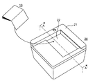
- FIG. 1 is a perspective view showing an appearance of a reading device 20 according to the first embodiment.
- the reading device 20 includes a housing 21 having an opening in the upper part (first surface), and a reading window member 22 fitted in the opening.
- the housing 21 accommodates various members to be described later.
- the surface to be read of the reading object 10 is placed on the upper surface of the reading window member 22, the surface to be read of the reading object 10 is placed.
- the reading window member 22 is made of a light transmissive resin such as glass or organic glass.
- An antireflection sheet, an antireflection film, a scattering prevention sheet, or the like may be bonded to the surface of the reading window member 22.
- the reading device 20 includes an imaging device inside, and the imaging device images the surface to be read through the reading window member 22.
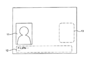
- FIG. 2 is a diagram illustrating an example of a reading surface of the reading object 10.
- the reading object 10 is, for example, a passport.
- a face photograph 11, passport data 12, and a figure 13 for preventing forgery are arranged on the surface to be read.
- the figure 13 for preventing counterfeiting is printed using a paint that fluoresces in response to ultraviolet rays.
- the reading device 20 optically reads information such as a face photograph 11, passport data 12, and a figure 13 from the surface to be read of the reading object 10.
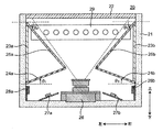
- FIG. 3 is a cross-sectional view showing the configuration of the reading device 20 corresponding to the A-A ′ cross section of FIG.
- the reading device 20 includes the housing 21 and the reading window member 22.
- the reading device 20 includes first irradiation units 27a and 27b that irradiate infrared light and second irradiation units 28a and 28b that irradiate visible light.
- the reading device 20 includes an imaging device 26 and a third irradiation unit 29 that irradiates ultraviolet light.
- the reading device 20 includes a first diffusion unit and a second diffusion unit.
- the first diffusing section includes a light transmissive first diffusion plate 24a and a light transmissive second diffusion plate 25a.
- the second diffusing section includes a light transmissive third diffusing plate 24b and a light transmissive fourth diffusing plate 25b.
- the reading device 20 includes light diffusion type reflection plates 23a and 23b.
- the first diffusion unit and the second diffusion unit transmit incident light and diffuse it.
- “transmitting and diffusing” means that light transmitted through an object spreads and scatters at various angles due to fine unevenness of the object.
- the first diffusion portion and the second diffusion portion are made of glass or organic glass such as acrylic.
- the light diffusion type reflectors 23a and 23b diffusely reflect incident light.
- “diffuse reflection” means that light incident on an object is reflected at various angles by fine unevenness of the object.
- the reflection plates 23a and 23b are made of, for example, a reflection plate made of aluminum or the like and coated with a white material having high diffuse reflection, a reflection sheet, white glass or resin plate material having high diffusion reflection. May be.
- the reflectors 23 a and 23 b of the present embodiment are disposed on the side walls inside the casing 21, but may be integrally formed with the casing 21. Or the whole side wall of the housing
- casing 21 may be comprised with a reflecting plate.
- the first irradiation units 27a and 27b include a substrate and a plurality of infrared light sources mounted on the substrate.
- the infrared light source emits infrared light.
- a circuit for driving an infrared light source is disposed on the substrate.
- the first irradiation units 27a and 27b irradiate near infrared rays having a wavelength of 0.7 to 2.5 ⁇ m, for example.
- Each of the first irradiation units 27a and 27b includes six infrared LEDs as an infrared light source.
- the six infrared LEDs are arranged in a line in the depth direction (a direction orthogonal to both the left and right directions and the up and down direction) in FIG.
- the 1st irradiation parts 27a and 27b are provided with surface mount type infrared light LED, you may be provided with infrared light LED of other shapes, such as a shell type.
- the first irradiators 27a and 27b are used, for example, to clearly image each character of the passport data 12 on the surface to be read in FIG.
- the infrared LED used in the present embodiment has a half angle of about 50 °.
- the “half-angle” refers to an angle at which the luminous intensity is halved with respect to the luminous intensity in the front direction.
- the second irradiation units 28a and 28b include a substrate and a plurality of visible light sources mounted on the substrate.
- the visible light source emits visible light.
- a circuit for driving the visible light source is disposed on the substrate.
- Each of the second irradiation units 28a and 28b includes four white light LEDs as a visible light source.
- the four white light LEDs are arranged in a line in the depth direction (a direction orthogonal to both the left-right direction and the up-down direction) in FIG.
- the second irradiation units 28a and 28b include surface-mounted white light LEDs, but may include white light LEDs of other shapes such as a shell type.
- the white light LED used in the present embodiment has a half angle of about 120 °.
- the imaging device 26 images the surface to be read of the reading object 10 placed on the upper surface of the reading window member 22 through the reading window member 22.
- the imaging device 26 includes an imaging sensor, a wide-angle lens, a circuit that drives the imaging sensor, and the like. Since the imaging device 26 includes the wide-angle lens, the imaging device 26 can be arranged so that the entire surface to be read is kept at the angle of view without increasing the distance between the reading window member 22 and the imaging device 26. . Therefore, the reading device 20 does not need to include a mirror that bends the optical path from the surface to be read and collects the light on the imaging device. Therefore, the reading device 20 can acquire an image with little illumination unevenness due to the visible light source.
- the third irradiation unit 29 includes a substrate and a plurality of ultraviolet light sources mounted on the substrate.
- the ultraviolet light source emits ultraviolet light.
- a circuit for driving a plurality of ultraviolet light sources is disposed on the substrate.
- the ultraviolet light source irradiates ultraviolet light having a wavelength of about 10 to 400 nm.
- the 3rd irradiation part 29 is provided with eight ultraviolet light LED as an ultraviolet light source. Although the 3rd irradiation part 29 is provided with a bullet-type ultraviolet light LED, you may be provided with ultraviolet light LED of other shapes, such as a surface mount type.
- the ultraviolet LED used in the present embodiment has a half angle of about 15 °.
- the 3rd irradiation part 29 is used in order to make the figure 13 for anti-counterfeiting of FIG. 2 fluorescent, for example.
- the reading window member 22 is fitted into the upper opening of the housing 21.
- the imaging device 26 is disposed on the bottom inside the housing 21 (on the second surface facing the first surface) below the reading window member 22 so that the entire reading window member 22 falls within the angle of view.
- the reflection plate 23 a is disposed on the left side wall (first side wall) that connects the first surface and the second surface inside the housing 21 below the reading window member 22.
- the first diffusion plate 24 a is disposed on the left side wall inside the housing 21 so as to be inclined upward.
- the second diffusion plate 25a is disposed above the light transmission type first diffusion plate 24a so as to be inclined downward with respect to the left side wall inside the housing 21.
- the first diffusion plate 24 a is arranged to be inclined at an angle of ⁇ 1 with respect to the normal line of the left side wall inside the housing 21.
- the second diffusion plate 25a is arranged to be inclined at an angle of ⁇ 2 with respect to the normal line of the left side wall inside the housing 21.
- ⁇ 1 is 30 ° and ⁇ 2 is 50 °.
- 2nd irradiation part 28a is arrange
- the first irradiation unit 27a is disposed on the bottom of the casing 21 so as to face the first diffusion plate 24a.
- the reflection plate 23b is disposed on the right side wall (second side wall) that connects the first surface and the second surface inside the housing 21 symmetrically with respect to the reflection plate 23a about the optical axis of the imaging device 26. Is done.
- the third diffusion plate 24b is disposed on the right side wall inside the housing 21 so as to be inclined upward.
- the fourth diffusion plate 25b is disposed above the third diffusion plate 24b and inclined downward with respect to the right side wall inside the housing 21.
- the third diffusing plate 24 b is disposed to be inclined upward at an angle of ⁇ 3 with respect to the normal line of the right side wall inside the housing 21.
- Fourth diffusion plate 25b is at an angle of theta 4 with respect to the normal of the casing 21 inside of the right side wall is disposed inclined downward. For example, ⁇ 3 is 30 ° and ⁇ 4 is 50 °.
- the second irradiation unit 28b is arranged on the right side wall inside the housing 21 symmetrically with respect to the second irradiation unit 28a with the optical axis of the imaging device 26 as the center.
- the first irradiation unit 27b is disposed on the bottom of the housing 21 so as to face the third diffusion plate 24b symmetrically about the optical axis of the imaging device 26 with respect to the first irradiation unit 27a.
- 3rd irradiation part 29 is arrange
- the reading apparatus 20 having the above configuration will be described.
- a surface to be read of the reading object 10 is placed on the upper surface of the reading window member 22.
- the reading device 20 irradiates the surface to be read of the reading object 10 with infrared light, visible light, and ultraviolet light, images the surface to be read, and acquires an image.
- the reading device 20 further includes a communication unit (not shown), and transmits the captured image to an external device connected via the communication unit. When the external device receives the captured image, the external device uses the image for various analyses.
- the first irradiation units 27a and 27b irradiate infrared light.
- the 2nd irradiation parts 28a and 28b irradiate visible light.
- Infrared light from the first irradiation units 27a and 27b and visible light from the second irradiation units 28a and 28b are diffused by the first diffusion unit, the second diffusion unit, and the reflectors 23a and 23b.
- the surface to be read of the reading object 10 is illuminated with diffused infrared light or visible light.
- the imaging device 26 images the surface to be read of the reading object 10 and acquires an image.
- the communication unit transmits the acquired image to the external device.
- 3rd irradiation part 29 irradiates with ultraviolet light.
- the reading surface of the reading object 10 directly irradiates the reading surface of the reading object 10 without being diffused by the first diffusing unit, the second diffusing unit, and the reflection plates 23a and 23b.
- the figure 13 for preventing forgery arranged on the surface to be read of the reading object 10 is made fluorescent by the directly irradiated ultraviolet light.
- the imaging device 26 images the surface to be read of the reading object 10 and acquires an image.
- the communication unit transmits the acquired image to the external device.
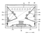
- FIG. 4 is a diagram illustrating a state in which visible light from the second irradiation unit 28 a is diffused inside the reading device 20. Part of the visible light from the second irradiation unit 28a is incident on the first diffusion plate 24a. The first diffusion plate 24a transmits and diffuses visible light incident from the second irradiation unit 28a.
- the reflection plate 23a diffusely reflects the visible light incident from the first diffusion plate 24a.
- Part of the visible light diffusely reflected from the reflecting plate 23a is incident on the second diffusing plate 25a.
- the second diffusion plate 25a transmits and diffuses visible light incident from the reflection plate 23a.
- Part of the visible light that has been transmitted and diffused from the second diffusion plate 25 a passes through the reading window member 22.
- a surface to be read of the reading object 10 placed on the reading window member 22 is illuminated with visible light transmitted through the reading window member 22.
- the second diffusion plate 25a transmits and diffuses the incident visible light from the first diffusion plate 24a. Part of the visible light that has been transmitted and diffused from the second diffusion plate 25 a passes through the reading window member 22. A surface to be read of the reading object 10 placed on the reading window member 22 is illuminated with visible light transmitted through the reading window member 22.
- the third diffusion plate 24b transmits and diffuses visible light incident from the second irradiation unit 28a.
- the reflection plate 23b diffuses and reflects the incident visible light from the third diffusion plate 24b.
- Part of the visible light diffused and reflected from the reflection plate 23b is incident on the fourth diffusion plate 25b.
- the fourth diffusion plate 25b transmits and diffuses visible light incident from the reflection plate 23b.
- Part of the visible light that has been transmitted and diffused from the fourth diffusion plate 25 b passes through the reading window member 22.
- a surface to be read of the reading object 10 placed on the reading window member 22 is illuminated with visible light transmitted through the reading window member 22.
- the fourth diffusion plate 25b transmits and diffuses visible light incident from the third diffusion plate 24b. Part of the visible light that has been transmitted and diffused from the fourth diffusion plate 25 b passes through the reading window member 22. A surface to be read of the reading object 10 placed on the reading window member 22 is illuminated with visible light transmitted through the reading window member 22.
- Visible light from the second irradiation unit 28b is diffused in a bilaterally symmetric direction around the optical axis of the imaging device 26 with respect to the visible light from the second irradiation unit 28a, and illuminates the read surface.
- the half-angle of the white light LED used as the visible light source is about 120 °.
- the first diffusing plate 24a and the third diffusing plate 24b are arranged so that visible light from the visible light source does not reach the reading surface over the range of the half angle of the white light LED. Therefore, the surface to be read is not directly illuminated by visible light having a high luminous intensity. Therefore, the reading device 20 of the present embodiment can acquire an image with little illumination unevenness due to a visible light source.
- the reading device 20 has a gap between the imaging device 26 and the upper side of the first diffusion plate 24a and between the imaging device 26 and the upper side of the third diffusion plate 24b. Since part of the visible light from the second irradiation units 28a and 28b passes through the gap, the reading device 20 can acquire an image with little illumination unevenness due to the visible light source. Further, the first diffusion plate 24 a and the third diffusion plate 24 b are not large enough to enter the viewing angle of the imaging device 26, and the second diffusion plate 25 a and the fourth diffusion plate 25 b do not enter the viewing angle of the imaging device 26. Inclined.
- FIG. 5 is a diagram illustrating a state in which infrared light from the first irradiation unit 27a is diffused inside the reading apparatus. Part of the infrared light from the first irradiation unit 27a is incident on the first diffusion plate 24a. The first diffusion plate 24a transmits and diffuses the incident infrared light from the first irradiation unit 27a.
- a part of the diffused infrared light from the first diffusion plate 24a is incident on the reflection plate 23a.
- the reflection plate 23a diffusely reflects the infrared light incident from the first diffusion plate 24a.
- Part of the infrared light diffused from the reflecting plate 23a is incident on the second diffusing plate 25a.
- the second diffusion plate 25a transmits and diffuses the infrared light incident from the reflection plate 23a.
- Part of the infrared light diffused from the second diffusing plate 25 a passes through the reading window member 22.
- the surface to be read of the reading object 10 placed on the reading window member 22 is illuminated with infrared light transmitted through the reading window member 22.
- the second diffusion plate 25a transmits and diffuses infrared light incident from the first diffusion plate 24a.
- a part of the diffused infrared light from the second diffusion plate 25 a passes through the reading window member 22.
- the surface to be read of the reading object 10 placed on the reading window member 22 is illuminated with infrared light transmitted through the reading window member 22.
- the infrared light from the first irradiation unit 27b is diffused in a bilaterally symmetric direction around the optical axis of the imaging device 26 with respect to the infrared light from the first irradiation unit 27a described above to illuminate the surface to be read. To do.
- the half-angle of the infrared LED used as the infrared light source is about 50 °.
- the first diffusing plate 24a and the third diffusing plate 24b are arranged so that the infrared light from the infrared light source does not reach the read surface over the range of the half angle of the infrared light LED. Therefore, the surface to be read is not illuminated by infrared light having a high luminous intensity. Therefore, the reading device 20 of the present embodiment can acquire an image with little illumination unevenness due to the infrared light source.
- UV light from the third irradiation unit 29 passes through the reading window member 22 without passing through the first diffusion unit, the second diffusion unit, and the reflection plates 23a and 23b.
- the ultraviolet light transmitted through the reading window member 22 fluoresces, for example, the figure 13 for preventing counterfeiting in FIG.
- the reading device 20 of the present embodiment causes the ultraviolet light from the third irradiation unit 29 to reach the surface to be read without passing through the first diffusing unit, the second diffusing unit, and the reflectors 23a and 23b. Accordingly, a resin material that can be deteriorated by ultraviolet rays or a resin material that absorbs ultraviolet rays can be used as the first diffusion portion, the second diffusion portion, and the reflectors 23a and 23b.
- the reading device 20 includes the housing 21, the first irradiation unit 27a, the imaging device 26, and the first diffusion unit.
- the casing 21 has an opening in which a transparent reading window member 22 is arranged at the upper part (first surface).
- the first irradiation unit 27a emits infrared light.
- the imaging device 26 is disposed on the bottom (second surface) facing the top inside the housing so that the optical axis faces the reading window member 22.
- the first diffusion part is disposed on the left side wall (first side wall) that connects the upper part and the bottom part inside the casing 21.
- the first diffusion unit diffuses infrared light from the first irradiation unit 27a.
- the first diffusing section includes a light transmission type first diffusion plate 24a and a light transmission type second diffusion plate 25a.
- the first diffusion plate 24a is disposed on the bottom side of the left side wall so as to be inclined in the upper direction.
- the second diffusion plate 25a is disposed on the upper side of the left side wall so as to be inclined toward the bottom.
- the first irradiation unit 27 a is arranged between the first diffusion plate 24 a and the bottom of the housing 21.
- the infrared light from the first irradiation unit 27a is diffused through the first diffusion unit and irradiates the reading window member 22, so that the reading device 20 has uneven illumination due to the first irradiation unit 27a. A small number of images can be acquired.
- the reading device 20 further includes a light diffusion type reflection plate 23a.
- the reflection plate 23 a is attached to the left side wall of the housing 21.
- the reflecting plate 23a diffuses and reflects the light from the first diffusing section, so that the reading device 20 can use the light efficiently.
- the reading device 20 further includes a second irradiation unit 28a that irradiates visible light.
- the second irradiation unit 28 a is disposed between the first diffusion plate 24 a and the bottom of the housing 21. Visible light from the second irradiation unit 28a is diffused by the first diffusion unit.
- the visible light from the second irradiation unit 28a is diffused through the first diffusion unit and irradiates the reading window member 22, so that the reading device 20 has little illumination unevenness due to the second irradiation unit 28a. Images can be acquired.
- the reading device 20 further includes a third irradiation unit 29 that irradiates ultraviolet light.
- the third irradiation unit 29 is disposed between the upper part of the housing 21 and the first diffusion unit.
- the ultraviolet light from the third irradiation unit 29 reaches the surface to be read without passing through the first diffusion unit and the reflection plate 23a. Therefore, a resin material that can be deteriorated by ultraviolet rays or a resin material that absorbs ultraviolet rays can be used as the material of the first diffusion portion, the second diffusion portion, and the reflectors 23a and 23b.
- the imaging device 26 is arranged so that the entire reading window member 22 is included within the range of the angle of view. At this time, the imaging device 26 may include a wide-angle lens.
- the imaging device 26 can be arranged so that the entire surface to be read falls within the angle of view without increasing the distance between the reading window member 22 and the imaging device 26. Unlike a conventional reading device, it is not necessary to provide a mirror that bends the optical path from the surface to be read and collects the light on the imaging device. Therefore, the present disclosure can provide a small reader.
- the reading device 20 has a gap between the upper side of the first diffusion plate 24 a and the imaging device 26.
- part of the visible light from the second irradiation units 28a and 28b passes through the gap, so that the reading device 20 can acquire an image with little illumination unevenness due to the visible light source.
- the first diffusion plate 24a is arranged so that the infrared light from the first irradiation unit 27a does not reach the reading window member 22 directly over the range of the half angle of the first irradiation unit.
- the surface to be read is not directly illuminated by infrared light having a high luminous intensity. Therefore, the reading device 20 can acquire an image with little illumination unevenness due to the infrared light source.
- the first diffuser plate 24a is arranged so that the visible light from the second irradiation unit 28a does not directly reach the reading window member 22 over the range of the half angle of the second irradiation unit.
- the surface to be read is not directly illuminated by visible light having a high luminous intensity. Therefore, the reading device 20 can acquire an image with little illumination unevenness due to the visible light source.
- the reading device 20 further includes a second diffusion unit.
- the second diffusing unit is disposed on the right side wall (second side wall) facing the left side wall inside the housing 21.
- the second diffusion unit diffuses the infrared light from the first irradiation unit 27b.
- the second diffusing section includes a light transmission type third diffusion plate 24b and a light transmission type fourth diffusion plate 25b.
- the third diffusion plate 24b is disposed to be inclined in the upper direction on the bottom side of the right side wall.
- the fourth diffusion plate 25b is disposed on the upper side of the right side wall so as to be inclined toward the bottom.
- the reading device 20 further includes a light diffusion type reflection plate 23b.
- the reflection plate 23 b is attached to the right side wall of the housing 21.
- the reflecting plate 23b diffuses and reflects the light from the second diffusing unit, so that the reading device 20 can use the light efficiently.
- the first irradiation unit 27 b is disposed between the first diffusion plate 24 a and the bottom of the housing 21.
- the infrared light from the first irradiation unit 27b is diffused through the first diffusion unit and irradiates the reading window member 22, so that the reading device 20 has uneven illumination due to the first irradiation unit 27b. A small number of images can be acquired.
- the reading device 20 further includes a second irradiation unit 28b that irradiates visible light.
- the second irradiation unit 28 b is disposed between the first diffusion plate 24 a and the bottom of the housing 21.
- the visible light from the second irradiation unit 28b is diffused through the second diffusion unit and irradiates the reading window member 22, so that the reading device 20 has less uneven illumination due to the second irradiation unit 28b. Images can be acquired.
- the first diffusing plate 24a has a size that does not enter the viewing angle of the imaging device 26, and the second diffusing plate 25a is disposed so as not to enter the viewing angle of the imaging device 26.
- Embodiment 2 In this embodiment, several structures of a reading device having a structure different from that in Embodiment 1 are described. 6A, 6B, 7A, 7B, and 8 are cross-sectional views showing another embodiment of the reading apparatus.
- the second irradiation unit 28 a is disposed on the left side wall inside the housing 21 below the light diffusion type reflection plate 23 a.
- the second irradiation unit 28a of the reading device 20A of FIG. 6A is arranged on the left side surface of the imaging device 26 so that the optical axis of the second irradiation unit 28a is orthogonal to the left side wall inside the housing 21. .
- the second irradiation unit 28b of the reading device 20A is symmetrical to the second irradiation unit 28a, and the right side of the imaging device 26 so that the optical axis of the second irradiation unit 28b is orthogonal to the right side wall inside the housing 21. Placed on the surface.
- the first diffusion plate 24 a is disposed on the left side wall inside the housing 21 so as to be inclined upward.
- the first diffusion plate 24a of FIG. 6B is arranged orthogonal to the left side wall inside the housing 21.
- the third diffusion plate 24b is disposed so as to be bilaterally symmetrical with the first diffusion plate 24a and orthogonal to the right side wall inside the housing 21.
- the reading device 20C includes a fourth irradiation unit 30b in place of the first irradiation unit 27b and the second irradiation unit 28b in the configuration of FIG.
- Each of the fourth irradiation units 30a and 30b includes a substrate and a plurality of infrared light sources and visible light sources mounted on the substrate.
- the fourth irradiation unit 30a includes four white light LEDs 30a1 as visible light sources and six infrared light LEDs 30a2 as infrared light sources.
- the fourth irradiation unit 30b includes four white light LEDs 30b1 as visible light sources and six infrared light LEDs 30b2 as infrared light sources.
- the six infrared LEDs 30a2 are arranged in a line on the substrate.
- the four white light LEDs 30a1 are arranged in a row on the substrate adjacent to the row of the infrared light LEDs 30a2.
- the 4th irradiation part 30b has the same structure as the 4th irradiation part 30a.
- the fourth irradiation unit 30 a is disposed to be inclined to the bottom surface of the housing 21 so that the optical axis thereof is orthogonal to the main surface of the first diffusion plate 24 a.
- the 4th irradiation part 30b is also inclined and arrange
- the first diffusion plate 24a is arranged orthogonal to the left side wall inside the housing 21. Further, the third diffusion plate 24 b is disposed orthogonal to the right side wall inside the housing 21.
- the first irradiation unit 27a is arranged at the bottom of the casing 21 below the first diffusion plate 24a, and is arranged so that the optical axis thereof is orthogonal to the main surface of the first diffusion plate 24a.
- the 1st irradiation part 27b is also arrange
- the reading device 20 in FIG. 3 includes a third irradiation unit 29 that irradiates the inner wall of the housing 21 with ultraviolet light.
- the reading device 20E includes the third irradiation unit 29 on the left and right side walls and the front side wall inside the housing 21.
- 3 includes a third irradiation unit 29 that irradiates the left and right side walls inside the housing 21 with ultraviolet light.
- the reading device 20E includes the third irradiation unit 29 on the left and right side walls and the front side wall inside the housing 21.
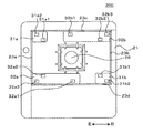
- FIGS. 9 and 10 are diagrams for explaining the reading device 20E of FIG.
- FIG. 9 is a top view of the reading device 20E from which the reading window member 22 and the third irradiation unit 29 of FIG. 8 are removed.
- the reading device 20E includes four transmission type diffusion plates 25c to 25f as shown in FIG. 9 instead of the second diffusion plate 25a and the fourth diffusion plate 25b.
- the reading device 20 ⁇ / b> E further includes four ribs 33 a to 33 d that are erected on the bottom of the housing 21 and are arranged so as to surround the side of the imaging device 26. Prepare.
- the diffusion plates 25c to 25f are respectively supported and arranged by the ribs 33a to 33d and the wall inside the housing 21.
- the reading device 20E includes a transmissive diffusion plate 24c in place of the first diffusion plate 24a and the third diffusion plate 24b in the configuration of FIG. As shown in FIG. 8, the diffusing plate 24 c is disposed between the ribs 33 a to 33 d and the wall inside the housing 21.
- FIG. 11 is a top view of the reading device 20E from which the diffusion plates 25c to 25f and the diffusion plate 24c are removed in FIGS.
- the reading device 20 according to the first embodiment (FIG. 3) includes light diffusion type reflection plates 23 a and 23 b on the left and right side walls inside the housing 21.
- the reading device 20E also includes light diffusion type reflection plates 23c and 23d on the inner and rear walls inside the housing 21.
- the reader 20E replaces the first irradiation units 27a and 27b and the second irradiation units 28a and 28b with the irradiation units 31a, 31b, 32a, and 32b of FIG. Is provided.
- Each of the irradiation units 31a, 31b, 32a, and 32b includes a substrate and a visible light source and an infrared light source mounted on the substrate.
- the irradiation units 31 a and 32 b are arranged close to the back side wall inside the housing 21.
- the irradiation unit 31a includes one white light LED 31a1 as a visible light source and one infrared light LED 31a2 as an infrared light source.
- the white light LED 31a1 is disposed at the corner closest to the imaging device 26, and the infrared light LED 31a2 is disposed at the corner farthest from the imaging device 26.
- the irradiation unit 32b includes two infrared LEDs 32b1 and 32b3 as infrared light sources and one white light LED 32b2 as a visible light source.
- the infrared light LED 32b1 is disposed close to the center in the left-right direction of the back side wall inside the housing 21, and the white light LED 32b2 and the infrared light LED 32b3 are respectively white light of the irradiation unit 31a. It arrange
- the irradiation units 31b and 32a are arranged close to the front side wall inside the housing 21.
- the irradiation unit 31b includes one white light LED 31b1 as a visible light source and one infrared light LED 31b2 as an infrared light source.
- the irradiation unit 31b is arranged to be symmetric with the irradiation unit 31a with respect to the optical axis of the imaging device 26.
- the irradiation unit 32a includes two infrared light LEDs 32a1 and 32a3 as infrared light sources and one white light LED 32a2 as a visible light source.
- the irradiation unit 32 a is arranged so as to be symmetric with respect to the irradiation unit 32 b with respect to the optical axis of the imaging device 26.
- the reading device 20E can be provided with the diffusion plates 25c to 25f from four directions, it is possible to acquire an image with little illumination unevenness by the irradiation units 31a, 31b, 32a, and 32b.
- the reading device 20 includes a point light source as a visible light source, an infrared light source, and an ultraviolet light source, but is not necessarily limited thereto.
- a line light source or a surface light source made of an organic EL material may be used.
- the first irradiation units 27a and 27b include six infrared LEDs as an infrared light source, but may include different numbers of infrared LEDs.
- the second irradiation units 28a and 28b include four white light LEDs as visible light sources, but may include different numbers of white light LEDs.
- the reading device 20 uses the white light LED as the visible light source, but may use an LED other than the white light.
- the reading device 20 includes a visible light source and an ultraviolet light source, but the reading device 20 may not include a visible light source and / or an ultraviolet light source.
- each of the second irradiation units 28a and 28b is disposed on the side wall inside the housing 21, but is not necessarily limited thereto.
- the second irradiating units 28a and 28b are configured such that the first diffusing plate 24a and the third diffusing plate 24b transmit visible light from the second irradiating units 28a and 28b to an angular range of half angles of the second irradiating units 28a and 28b. It may be arranged at another position so as not to reach the reading window.
- the first irradiation units 27a and 27b are arranged to face the first diffusion plate 24a and the third diffusion plate 24b, respectively, but are not necessarily limited thereto.
- the first irradiating units 27a and 27b are configured such that the first diffusing plate 24a and the third diffusing plate 24b receive infrared light from the first irradiating units 27a and 27b and the half-angle angles of the first irradiating units 27a and 27b. It may be arranged in another position so as not to reach the reading window over the range.
- the fourth diffusing plate 25b) and the reflecting plates 23a and 23b have a pair of left and right symmetrical configurations around the optical axis of the imaging device 26, but are not necessarily limited thereto.
- the configuration of only one side such as the first irradiation unit 27a, the second irradiation unit 28a, the first diffusion unit (the first diffusion plate 24a, the second diffusion plate 25a), and the reflection plate 23a is very good.
- the optical axis of the imaging device 26 is the vertical direction, but the present invention is not necessarily limited to this.
- the optical axis of the imaging device 26 may be a horizontal direction or an obliquely upward direction.
- the imaging device 26 is arranged at the bottom inside the housing 21, just below the reading window member 22, so that the optical axis faces the reading window member 22.
- the housing 21 has an opening on the side surface (first surface), and the reading window member 22 is disposed in the opening.
- the imaging device 26 may be disposed on the side surface (second surface) side facing the side surface (first surface) inside the housing so that the optical axis faces the reading window member 22.
- the first irradiation units 27a and 27b include a substrate and a plurality of infrared light sources mounted on the substrate, and the second irradiation units 28a and 28b are mounted on the substrate and the substrate.
- the third irradiation unit 29 includes a substrate and a plurality of ultraviolet light sources mounted on the substrate, but is not necessarily limited thereto.
- the first irradiation unit may include only a plurality of infrared light sources
- the second irradiation unit may include only a plurality of visible light sources
- the third irradiation unit may include only a plurality of ultraviolet light sources.
- the substrate (circuit) that controls each light source may be disposed inside the housing 21.
- the fourth irradiation unit 30a includes six infrared LEDs 30a2 as infrared light sources, but may include a different number of infrared LEDs 30a2. Moreover, although the 4th irradiation part 30b was provided with six infrared light LED30b2 as an infrared light source, you may be provided with a different number of infrared light LED30b2.
- the fourth irradiation unit 30a includes four white light LEDs 30a1 as white light sources, but may include a different number of white light LEDs 30a1. Moreover, although the 4th irradiation part 30b was provided with four infrared light LED30b1 as an infrared light source, you may be provided with a different number of infrared light LED30b1.
- the 3rd irradiation part 29 was arrange
- the third irradiation unit 29 may be disposed between the first diffusion unit and the bottom.
- the reading object 10 may be anything that can be read by the imaging device 26, such as a license, a document, a photograph, or a form.
- Reading device 21 Housing 22 Reading window member 23a, 23b Reflector plate 24a, 24b, 25a, 25b Diffuser plate 26 Imaging device 27a, 27b First irradiation unit 28a, 28b Second irradiation unit 29 Third irradiation unit 30a, 30b First 4 irradiation unit
Landscapes
- Engineering & Computer Science (AREA)
- Multimedia (AREA)
- Signal Processing (AREA)
- Environmental & Geological Engineering (AREA)
- Facsimile Scanning Arrangements (AREA)
- Light Sources And Details Of Projection-Printing Devices (AREA)
- Studio Devices (AREA)
- Image Input (AREA)
Abstract
本開示の読取装置(20)は、筐体(21)と、第1照射部(27a)と、撮像装置(26)と、第1拡散部とを備える。筐体(21)は、その上部に、透明な読取窓部材(22)を配置した開口を有する。第1照射部(27a)は、赤外光を照射する。撮像装置(26)は、筐体の内部の上部と対向する底部に光軸が読取窓部材(22)を向くように配置される。第1拡散部は、筐体(21)の内部において上部と底部とを接続する左側壁に配置される。第1拡散部は、第1照射部からの赤外光を拡散する。第1拡散部は、光透過型の第1拡散板(24a)と、光透過型の第1拡散板(24b)とで構成される。第1拡散板(24a)は、左側壁の底面側に上部の方向に傾斜して配置される。第2拡散板(25a)は、左側壁の上面側に底部の方向に傾斜して配置される。
Description
本発明は、読取対象物を撮像して読取る読取装置に関する。
特許文献1は、パスポートなどの読取対象物の被読取面が載置される載置面と、被読取面を照明する赤外光源または可視光源を備える照明光源と、被読取面を撮像する撮像部と、被読取面からの光路を変更して撮像部に集光させるミラーとを備える読取装置を開示している。照明光源を局所的に載置面に近接して配置することによって、読取装置は、照明ムラの少ない画像を取得する。
本開示は、照明ムラを低減して、読取精度を向上した読取装置を提供する。
本開示の読取装置は、筐体と、第1照射部と、撮像装置と、第1拡散部とを備える。筐体は、その上部に、透明な読取窓部材を配置した開口を有する。第1照射部は、赤外光を照射する。撮像装置は、筐体の内部の上部と対向する底部に光軸が読取窓部材を向くように配置される。第1拡散部は、筐体の内部において上部と底部とを接続する左側壁に配置される。第1拡散部は、第1照射部からの赤外光を拡散する。第1拡散部は、光透過型の第1拡散板と、光透過型の第1拡散板とで構成される。第1拡散板は、左側壁の底面側に上部の方向に傾斜して配置される。第2拡散板は、左側壁の上面側に底部の方向に傾斜して配置される。
本開示によれば、照明ムラを低減して、読取精度を向上した読取装置を提供することができる。
以下、適宜図面を参照しながら、実施の形態を詳細に説明する。但し、必要以上に詳細な説明は省略する場合がある。例えば、既によく知られた事項の詳細説明や実質的に同一の構成に対する重複説明を省略する場合がある。これは、以下の説明が不必要に冗長になるのを避け、当業者の理解を容易にするためである。
なお、発明者(ら)は、当業者が本開示を十分に理解するために添付図面および以下の説明を提供するのであって、これらによって特許請求の範囲に記載の主題を限定することを意図するものではない。
(実施の形態1)
1.構成
図1は、実施の形態1に係る読取装置20の外観を示す斜視図である。読取装置20は、上部(第1面)に開口を有する筐体21と、当該開口に嵌め込まれた読取窓部材22とを備える。
1.構成
図1は、実施の形態1に係る読取装置20の外観を示す斜視図である。読取装置20は、上部(第1面)に開口を有する筐体21と、当該開口に嵌め込まれた読取窓部材22とを備える。
筐体21は、後述する種々の部材を収納する。読取窓部材22の上面には、読取対象物10の被読取面が載置される。読取窓部材22は、光透過性の、ガラス、または有機ガラスなどの樹脂によって構成される。読取窓部材22の表面には、反射防止シート、反射防止膜、飛散防止シートなどが貼り合わされてもよい。読取装置20は内部に撮像装置を備え、撮像装置は読取窓部材22越しに被読取面を撮像する。
図2は、読取対象物10の被読取面の一例を示す図である。読取対象物10は、例えば、パスポートである。被読取面には、顔写真11、旅券データ12、および偽造防止のための図形13などが配置されている。偽造防止のための図形13は、紫外線に反応して蛍光する塗料を用いて印刷されている。読取装置20は、読取対象物10の被読取面から、顔写真11、旅券データ12、および図形13等の情報を光学的に読み取る。
図3は、図1のA-A’断面に対応する読取装置20の構成を示す断面図である。上述したように、読取装置20は、筐体21および読取窓部材22を備える。読取装置20は、赤外光を照射する第1照射部27a,27bおよび可視光を照射する第2照射部28a,28bを備える。読取装置20は、撮像装置26、および紫外光を照射する第3照射部29を備える。読取装置20は、第1拡散部および第2拡散部を備える。第1拡散部は、光透過型の第1拡散板24aおよび光透過型の第2拡散板25aにより構成される。第2拡散部は、光透過型の第3拡散板24bおよび光透過型の第4拡散板25bにより構成される。読取装置20は、光拡散型の反射板23a,23bを備える。
第1拡散部および第2拡散部は、入射した光を透過して拡散する。ここで、「透過して拡散する」とは、物体を透過した光が、当該物体の細かい凹凸によって様々な角度で広がり散ることをいう。第1拡散部および第2拡散部は、ガラス、またはアクリルなどの有機ガラスで構成される。
光拡散型の反射板23a,23bは、入射した光を拡散反射する。ここで、「拡散反射」とは、物体に入射した光が、当該物体の細かい凹凸によって様々な角度で反射することをいう。本実施の形態の反射板23a,23bは、高い拡散性を有する白色の材料を含む白色板で構成されるが、これに限定されない。反射板23a,23bは、例えば、アルミニウムなどで構成される反射板に、拡散反射性の高い白塗装を施したものや、反射シート、拡散反射性の高い白いガラスや樹脂の板材などで構成されてもよい。本実施の形態の反射板23a,23bは筐体21の内部の側壁に配置されるが、筐体21と一体成形されていてもよい。あるいは、筐体21の側壁全体が反射板で構成されてもよい。
第1照射部27a,27bは、基板と、基板上に実装された複数の赤外光源とを含む。赤外光源は、赤外光を照射する。基板上には、赤外光源を駆動する回路が配置される。第1照射部27a,27bは、例えば、0.7~2.5μmの波長を有する近赤外光線を照射する。第1照射部27a,27bはそれぞれ、赤外光源として6個の赤外光LEDを備える。6個の赤外光LEDは、図3において奥行き方向(左右方向および上下方向の双方と直交する方向)に一列に整列して配置される。また、第1照射部27a,27bは、表面実装型の赤外光LEDを備えるが、砲弾型など他の形状の赤外光LEDを備えてもよい。第1照射部27a,27bは、例えば、図2の被読取面の旅券データ12の各文字を明瞭に撮像するために使用される。本実施の形態で使用する赤外光LEDは、50°程度の半減角を有する。ここで、「半減角」とは、正面方向への光度に対して、光度が半分になる角度のことをいう。
第2照射部28a,28bは、基板と、基板上に実装された複数の可視光源とを含む。可視光源は、可視光を照射する。基板上には、可視光源を駆動するための回路が配置される。第2照射部28a,28bはそれぞれ、可視光源として4個の白色光LEDを備える。4個の白色光LEDは、図3において奥行き方向(左右方向および上下方向の双方と直交する方向)に一列に整列して配置される。第2照射部28a,28bは、表面実装型の白色光LEDを備えるが、砲弾型など他の形状の白色光LEDを備えてもよい。本実施の形態で使用する白色光LEDは、120°程度の半減角を有する。
撮像装置26は、読取窓部材22を介して、読取窓部材22の上面に載置された、読取対象物10の被読取面を撮像する。撮像装置26は、撮像センサ、広角レンズ、撮像センサを駆動する回路などで構成される。撮像装置26が広角レンズを備えることにより、読取窓部材22と撮像装置26との間の距離を大きくすることなく、被読取面全体を画角に収めるように撮像装置26を配置することができる。したがって、読取装置20は、被読取面からの光路を曲げて撮像装置に集光させるミラーを備える必要がない。それ故、読取装置20は、可視光源による照明ムラが少ない画像を取得することができる。
第3照射部29は、基板と、基板上に実装された複数の紫外光源とを含む。紫外光源は紫外光を照射する。基板上には、複数の紫外光源を駆動するための回路が配置される。紫外光源は、約10~400nmの波長を有する紫外光を照射する。第3照射部29は、紫外光源として8個の紫外光LEDを備える。第3照射部29は、砲弾型の紫外光LEDを備えるが、表面実装型など他の形状の紫外光LEDを備えてもよい。本実施の形態で使用する紫外光LEDは、15°程度の半減角を有する。第3照射部29は、例えば、図2の偽造防止のための図形13を蛍光させるために使用される。
図3において、読取窓部材22は、筐体21の上部の開口に嵌め込まれて配置される。撮像装置26は、筐体21の内部の底部(第1面と対向する第2面側)において、読取窓部材22の下方に読取窓部材22全体が画角に収まるように配置される。
反射板23aは、読取窓部材22の下側において筐体21内部の第1面と第2面とを接続する左側壁(第1側壁)に配置される。第1拡散板24aは、筐体21内部の左側壁に上向きに傾斜して配置される。第2拡散板25aは、光透過型の第1拡散板24aの上方に筐体21内部の左側壁に対して下向きに傾斜して配置される。第1拡散板24aは、筐体21内部の左側壁の法線に対してθ1の角度で傾斜して配置される。第2拡散板25aは、筐体21内部の左側壁の法線に対してθ2の角度で傾斜して配置される。例えば、θ1は30°であり、θ2は50°である。
第2照射部28aは、反射板23aの下側において、筐体21内部の左側壁に配置される。第1照射部27aは、筐体21の底部に第1拡散板24aと対向して配置される。
反射板23bは、反射板23aに対して、撮像装置26の光軸を中心として左右対称に、筐体21内部の第1面と第2面とを接続する右側壁(第2側壁)に配置される。第3拡散板24bは、筐体21内部の右側壁に上向きに傾斜して配置される。第4拡散板25bは、第3拡散板24bの上方に筐体21内部の右側壁に対して下向きに傾斜して配置される。第3拡散板24bは、筐体21内部の右側壁の法線に対してθ3の角度で、上向きに傾斜して配置される。第4拡散板25bは、筐体21内部の右側壁の法線に対してθ4の角度で、下向きに傾斜して配置される。例えば、θ3は30°であり、θ4は50°である。
第2照射部28bは、第2照射部28aに対して、撮像装置26の光軸を中心として左右対称に、筐体21内部の右側壁に配置される。第1照射部27bは、第1照射部27aに対して、撮像装置26の光軸を中心として左右対称に、筐体21の底部に第3拡散板24bと対向して配置される。
第3照射部29は、第1拡散部および第2拡散部の上側(第1面側)において、筐体21内部の奥側壁に配置される。
2.動作
以上の構成を有する読取装置20の動作を説明する。読取窓部材22の上面に、読取対象物10の被読取面が載置される。読取装置20は、赤外光、可視光、および紫外光により読取対象物10の被読取面を照射し、被読取面を撮像して画像を取得する。読取装置20は、通信部(図示せず)をさらに備えており、当該通信部を介して接続された外部装置に、撮像した画像を送信する。外部装置は、撮像した画像を受信すると、当該画像を種々の解析に使用する。
以上の構成を有する読取装置20の動作を説明する。読取窓部材22の上面に、読取対象物10の被読取面が載置される。読取装置20は、赤外光、可視光、および紫外光により読取対象物10の被読取面を照射し、被読取面を撮像して画像を取得する。読取装置20は、通信部(図示せず)をさらに備えており、当該通信部を介して接続された外部装置に、撮像した画像を送信する。外部装置は、撮像した画像を受信すると、当該画像を種々の解析に使用する。
具体的には、第1照射部27a,27bは赤外光を照射する。第2照射部28a,28bは可視光を照射する。第1照射部27a,27bからの赤外光、および第2照射部28a,28bからの可視光は、第1拡散部、第2拡散部、および反射板23a,23bによって拡散される。読取対象物10の被読取面は、拡散された赤外光または可視光によって照明される。撮像装置26は読取対象物10の被読取面を撮像して画像を取得する。通信部は、取得した画像を外部装置に送信する。
第3照射部29は紫外光を照射する。読取対象物10の被読取面は、第1拡散部、第2拡散部、および反射板23a,23bによって拡散されることなく、読取対象物10の被読取面を直接照射する。読取対象物10の被読取面に配置される偽造防止のための図形13は、直接照射された紫外光によって蛍光させる。撮像装置26は読取対象物10の被読取面を撮像して画像を取得する。通信部は、取得した画像を外部装置に送信する。
3.光の拡散について
図4は、読取装置20の内部で、第2照射部28aからの可視光が拡散する様子を示す図である。第2照射部28aからの可視光の一部は、第1拡散板24aに入射する。第1拡散板24aは、第2照射部28aから入射した可視光を透過して拡散する。
図4は、読取装置20の内部で、第2照射部28aからの可視光が拡散する様子を示す図である。第2照射部28aからの可視光の一部は、第1拡散板24aに入射する。第1拡散板24aは、第2照射部28aから入射した可視光を透過して拡散する。
第1拡散板24aで拡散した可視光の一部は、反射板23aに入射する。反射板23aは、第1拡散板24aから入射した可視光を拡散反射する。反射板23aから拡散反射した可視光の一部は、第2拡散板25aに入射する。第2拡散板25aは、反射板23aから入射した可視光を透過して拡散する。第2拡散板25aから透過して拡散した可視光の一部は、読取窓部材22を透過する。読取窓部材22に載置された読取対象物10の被読取面は、読取窓部材22を透過した可視光によって照明される。
第1拡散板24aから拡散した可視光の別の一部は、第2拡散板25aに入射する。第2拡散板25aは、第1拡散板24aからの入射した可視光を透過して拡散する。第2拡散板25aから透過して拡散した可視光の一部は、読取窓部材22を透過する。読取窓部材22に載置された読取対象物10の被読取面は、読取窓部材22を透過した可視光によって照明される。
第2照射部28aからの拡散した可視光のさらに別の一部は、第3拡散板24bに入射する。第3拡散板24bは、第2照射部28aから入射した可視光を透過して拡散する。
第3拡散板24bから拡散した可視光の一部は、反射板23bに入射する。反射板23bは、第3拡散板24bからの入射した可視光を拡散反射する。反射板23bからの拡散反射した可視光の一部は、第4拡散板25bに入射する。第4拡散板25bは、反射板23bから入射した可視光を透過して拡散する。第4拡散板25bから透過して拡散した可視光の一部は、読取窓部材22を透過する。読取窓部材22に載置された読取対象物10の被読取面は、読取窓部材22を透過した可視光によって照明される。
第3拡散板24bから拡散した可視光の別の一部は、第4拡散板25bに入射する。第4拡散板25bは、第3拡散板24bから入射した可視光を透過して拡散する。第4拡散板25bから透過して拡散した可視光の一部は、読取窓部材22を透過する。読取窓部材22に載置された読取対象物10の被読取面は、読取窓部材22を透過した可視光によって照明される。
第2照射部28bからの可視光は、上述した第2照射部28aからの可視光に対して、撮像装置26の光軸を中心として左右対称な方向に拡散して被読取面を照明する。
本実施の形態において、可視光源として使用する白色光LEDの半減角は、120°程度である。第1拡散板24aおよび第3拡散板24bは、可視光源からの可視光を、白色光LEDの半減角の角度範囲にわたって、被読取面に到達させないように配置される。したがって、被読取面は、高い光度を有する可視光により直接照明されることはない。それ故、本実施の形態の読取装置20は、可視光源による照明ムラが少ない画像を取得することができる。
また、本実施の形態において、読取装置20は、撮像装置26と第1拡散板24aの上辺との間、および、撮像装置26と第3拡散板24bの上辺との間に間隙を有する。第2照射部28a,28bからの可視光の一部が当該間隙を通過するので、読取装置20は、可視光源による照明ムラが少ない画像を取得することができる。また、第1拡散板24aおよび第3拡散板24bは、撮像装置26の視角に入らない大きさで、第2拡散板25aおよび第4拡散板25bは、撮像装置26の視角に入らないように傾斜して配置される。
図5は、読取装置の内部で、第1照射部27aからの赤外光が拡散する様子を示す図である。第1照射部27aからの赤外光の一部は、第1拡散板24aに入射する。第1拡散板24aは、第1照射部27aからの入射した赤外光を透過して拡散する。
第1拡散板24aからの拡散した赤外光の一部は、反射板23aに入射する。反射板23aは、第1拡散板24aから入射した赤外光を拡散反射する。反射板23aから拡散した赤外光の一部は、第2拡散板25aに入射する。第2拡散板25aは、反射板23aから入射した赤外光を透過して拡散する。第2拡散板25aから拡散した赤外光の一部は、読取窓部材22を透過する。読取窓部材22に載置された読取対象物10の被読取面は、読取窓部材22を透過した赤外光によって照明される。
第1拡散板24aからの拡散した赤外光の別の一部は、第2拡散板25aに入射する。第2拡散板25aは、第1拡散板24aから入射した赤外光を透過して拡散する。第2拡散板25aからの拡散した赤外光の一部は、読取窓部材22を透過する。読取窓部材22に載置された読取対象物10の被読取面は、読取窓部材22を透過した赤外光によって照明される。
第1照射部27bからの赤外光は、上述した第1照射部27aからの赤外光に対して、撮像装置26の光軸を中心として左右対称な方向に拡散して被読取面を照明する。
本実施の形態において、赤外光源として使用する赤外光LEDの半減角は、50°程度である。第1拡散板24aおよび第3拡散板24bは、赤外光源からの赤外光を、赤外光LEDの半減角の角度範囲にわたって、被読取面に到達させないように配置される。したがって、被読取面は、高い光度を有する赤外光により照明されることはない。それ故、本実施の形態の読取装置20は、赤外光源による照明ムラが少ない画像を取得することができる。
第3照射部29からの紫外光は、第1拡散部、第2拡散部、および反射板23a,23bを介さずに、読取窓部材22を透過する。読取窓部材22を透過した紫外光は、例えば、図2の偽造防止のための図形13を蛍光させる。
本実施の形態の読取装置20は、第1拡散部、第2拡散部、および反射板23a,23bを介さずに、第3照射部29からの紫外光を、被読取面に到達させる。このことにより、第1拡散部、第2拡散部、および反射板23a,23bとして、紫外線によって劣化することがある樹脂材料や紫外線を吸収する樹脂材料を使用することができる。
4.まとめ
以上説明したように、読取装置20は、筐体21と、第1照射部27aと、撮像装置26と、第1拡散部とを備える。筐体21は、その上部(第1面)に、透明な読取窓部材22を配置した開口を有する。第1照射部27aは、赤外光を照射する。撮像装置26は、筐体の内部の上部と対向する底部(第2面)に光軸が読取窓部材22を向くように配置される。第1拡散部は、筐体21の内部において上部と底部とを接続する左側壁(第1側壁)に配置される。第1拡散部は、第1照射部27aからの赤外光を拡散する。第1拡散部は、光透過型の第1拡散板24aと、光透過型の第2拡散板25aとで構成される。第1拡散板24aは、左側壁の底部側に上部の方向に傾斜して配置される。第2拡散板25aは、左側壁の上部側に底部の方向に傾斜して配置される。
以上説明したように、読取装置20は、筐体21と、第1照射部27aと、撮像装置26と、第1拡散部とを備える。筐体21は、その上部(第1面)に、透明な読取窓部材22を配置した開口を有する。第1照射部27aは、赤外光を照射する。撮像装置26は、筐体の内部の上部と対向する底部(第2面)に光軸が読取窓部材22を向くように配置される。第1拡散部は、筐体21の内部において上部と底部とを接続する左側壁(第1側壁)に配置される。第1拡散部は、第1照射部27aからの赤外光を拡散する。第1拡散部は、光透過型の第1拡散板24aと、光透過型の第2拡散板25aとで構成される。第1拡散板24aは、左側壁の底部側に上部の方向に傾斜して配置される。第2拡散板25aは、左側壁の上部側に底部の方向に傾斜して配置される。
第1照射部27aは、第1拡散板24aと、筐体21の底部との間に配置される。
このことにより、第1照射部27aからの赤外光は、第1拡散部を介して拡散されて、読取窓部材22を照射するので、読取装置20は、第1照射部27aによる照明ムラが少ない画像を取得することができる。
読取装置20は、光拡散型の反射板23aをさらに備える。反射板23aは、筐体21の左側壁に取り付けられる。
このことにより、反射板23aは、第1拡散部からの光を拡散反射するので、読取装置20は、光を効率よく用いることができる。
読取装置20は、可視光を照射する第2照射部28aをさらに備える。第2照射部28aは、第1拡散板24aと、筐体21の底部との間に配置される。第2照射部28aからの可視光は、第1拡散部によって拡散される。
このことにより、第2照射部28aからの可視光は、第1拡散部を介して拡散されて、読取窓部材22を照射するので、読取装置20は、第2照射部28aによる照明ムラが少ない画像を取得することができる。
読取装置20は、紫外光を照射する第3照射部29をさらに備える。第3照射部29は、筐体21の上部と第1拡散部との間に配置される。
このことにより、第3照射部29からの紫外光は、第1拡散部および反射板23aを介さずに被読取面に到達する。したがって、第1拡散部、第2拡散部、および反射板23a,23bの材料として、紫外線によって劣化することがある樹脂材料や紫外線を吸収する樹脂材料を使用することができる。
撮像装置26は、読取窓部材22全体が画角の範囲内に含まれるように配置される。このとき、撮像装置26は広角レンズを備えてもよい。
このことにより、読取窓部材22と撮像装置26との間の距離を大きくすることなく、被読取面全体を画角に収めるように撮像装置26を配置することができるので、読取装置20は、従来の読取装置のように、被読取面からの光路を曲げて撮像装置に集光させるミラーを備える必要がない。したがって、本開示は、小型な読取装置を提供することができる。
読取装置20は、第1拡散板24aの上辺と撮像装置26との間に、間隙を有する。
このことにより、第2照射部28a,28bからの可視光の一部が当該間隙を通過するので、読取装置20は、可視光源による照明ムラが少ない画像を取得することができる。
第1拡散板24aは、第1照射部27aからの赤外光を、第1照射部の半減角の角度範囲にわたって、直接読取窓部材22に到達させないように配置される。
このことにより、被読取面は、高い光度を有する赤外光により直接照明されることはない。それ故、読取装置20は、赤外光源による照明ムラが少ない画像を取得することができる。
第1拡散板24aは、第2照射部28aからの可視光を、第2照射部の半減角の角度範囲にわたって、直接読取窓部材22に到達させないように配置される。
このことにより、被読取面は、高い光度を有する可視光により直接照明されることはない。それ故、読取装置20は、可視光源による照明ムラが少ない画像を取得することができる。
読取装置20は、第2拡散部をさらに備える。第2拡散部は、筐体21の内部において左側壁と対向する右側壁(第2側壁)に配置される。第2拡散部は、第1照射部27bからの赤外光を拡散する。第2拡散部は、光透過型の第3拡散板24bと、光透過型の第4拡散板25bとで構成される。第3拡散板24bは、右側壁の底部側に上部の方向に傾斜して配置される。第4拡散板25bは、右側壁の上部側に底部の方向に傾斜して配置される。
読取装置20は、光拡散型の反射板23bをさらに備える。反射板23bは、筐体21の右側壁に取り付けられる。
このことにより、反射板23bは、第2拡散部からの光を拡散反射するので、読取装置20は、光を効率よく用いることができる。
第1照射部27bは、第1拡散板24aと、筐体21の底部との間に配置される。
このことにより、第1照射部27bからの赤外光は、第1拡散部を介して拡散されて、読取窓部材22を照射するので、読取装置20は、第1照射部27bによる照明ムラが少ない画像を取得することができる。
読取装置20は、可視光を照射する第2照射部28bをさらに備える。第2照射部28bは、第1拡散板24aと、筐体21の底部との間に配置される。
このことにより、第2照射部28bからの可視光は、第2拡散部を介して拡散されて、読取窓部材22を照射するので、読取装置20は、第2照射部28bによる照明ムラが少ない画像を取得することができる。
第1拡散板24aは、撮像装置26の視角に入らない大きさで、第2拡散板25aは、撮像装置26の視角に入らないように傾斜して配置される。
(実施の形態2)
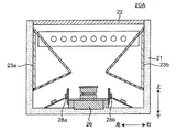
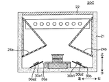
本実施の形態では、実施の形態1と異なる構成を有する読取装置の構成をいくつか説明する。図6A、図6B、図7A、図7B、および図8は、読取装置の別の実施の形態を示す断面図である。
本実施の形態では、実施の形態1と異なる構成を有する読取装置の構成をいくつか説明する。図6A、図6B、図7A、図7B、および図8は、読取装置の別の実施の形態を示す断面図である。
図6Aの読取装置20Aは、可視光を照射する第2照射部28a,28bの配置が図3の実施の形態1と異なる。実施の形態1の読取装置20において、図3に示すように、第2照射部28aは、光拡散型の反射板23aの下方において、筐体21内部の左側壁に配置されていた。これに対して、図6Aの読取装置20Aの第2照射部28aは、第2照射部28aの光軸が筐体21内部の左側壁と直交するように撮像装置26の左側面に配置される。同様に、読取装置20Aの第2照射部28bは、第2照射部28aと左右対称に、第2照射部28bの光軸が筐体21内部の右側壁と直交するように撮像装置26の右側面に配置される。
図6Bの読取装置20Bは、光透過型の第1拡散板24aの配置が図3の実施の形態1と異なる。実施の形態1の読取装置20において、図3に示すように、第1拡散板24aは、筐体21内部の左側壁に上向きに傾斜して配置されていた。これに対して、図6Bの第1拡散板24aは、筐体21内部の左側壁に対して直交して配置される。また、第3拡散板24bは、第1拡散板24aと左右対称に、筐体21内部の右側壁に対して直交して配置される。
図7Aの読取装置20Cは、実施の形態1(図3)の構成において、第1照射部27aおよび第2照射部28aに代えて、第4照射部30aを備える。さらに、読取装置20Cは、図3の構成において、第1照射部27bおよび第2照射部28bに代えて、第4照射部30bを備える。
第4照射部30a,30bはそれぞれ、基板と、基板上に実装された複数の赤外光源および可視光源とを含む。第4照射部30aは、可視光源として4個の白色光LED30a1と、赤外光源として6個の赤外光LED30a2を備える。第4照射部30bは、可視光源として4個の白色光LED30b1と、赤外光源として6個の赤外光LED30b2を備える。
第4照射部30aにおいて、6個の赤外光LED30a2は、基板上に一列に配置される。4個の白色光LED30a1は、赤外光LED30a2の列に隣接して、基板上に一列に配置される。第4照射部30bは、第4照射部30aと同様の構成を有する。
読取装置20Cにおいて、第4照射部30aは、その光軸が第1拡散板24aの主面と直交するように、筐体21の底面に傾けて配置される。同様に、第4照射部30bも、その光軸が第3拡散板24bの主面と直交するように、筐体21の底面に傾けて配置される。
図7Bにおいて、第1拡散板24aは、筐体21内部の左側壁に対して直交して配置される。さらに、第3拡散板24bは、筐体21内部の右側壁に対して直交して配置される。
また、第1照射部27aは、第1拡散板24aの下方において、筐体21の底部に配置され、その光軸が第1拡散板24aの主面と直交するように配置される。同様に、第1照射部27bも、第3拡散板24bの下方において、筐体21の底部に配置され、その光軸が第3拡散板24bの主面と直交するように配置される。
図8の読取装置20Eは、各照射部および各拡散部の構成が実施の形態1(図3)と異なる。図3の読取装置20は、筐体21内部の奥側壁に紫外光を照射する第3照射部29を備える。一方で、読取装置20Eは、筐体21内部の左右側壁および手前側壁にも第3照射部29を備える。また、図3の読取装置20は、筐体21内部の左右側壁に紫外光を照射する第3照射部29を備える。一方で、読取装置20Eは、筐体21内部の左右側壁および手前側壁にも第3照射部29を備える。
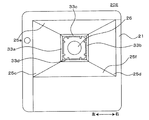
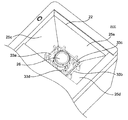
図9および図10は、図8の読取装置20Eを説明するための図である。図9は、図8の読取窓部材22および第3照射部29を除去した読取装置20Eの上面図である。読取装置20Eは、実施の形態1(図3)の構成において、第2拡散板25aおよび第4拡散板25bに代えて、図9のように4枚の透過型の拡散板25c~25fを備える。また、読取装置20Eは、図9および図10のように、筐体21の底部に立設して、撮像装置26の側部を包囲するように配置される4枚のリブ33a~33dをさらに備える。拡散板25c~25fはそれぞれ、リブ33a~33dおよび筐体21内部の壁によって支持されて配置される。
さらに、読取装置20Eは、図3の構成において、第1拡散板24aおよび第3拡散板24bに代えて、透過型の拡散板24cを備える。図8のように、拡散板24cは、リブ33a~33dと筐体21内部の壁との間に配置される。
図11は、図8および図9において、拡散板25c~25f、および拡散板24cを除去した読取装置20Eの上面図である。実施の形態1(図3)の読取装置20は、筐体21内部の左右側壁に、光拡散型の反射板23a,23bを備える。一方、読取装置20Eは、筐体21内部の奥側および手前側の壁にも光拡散型の反射板23c,23dを備える。
さらに、読取装置20Eは、実施の形態1(図3)の構成において、第1照射部27a,27bおよび第2照射部28a,28bに代えて、図11の照射部31a,31b,32a,32bを備える。照射部31a,31b,32a,32bはそれぞれ、基板と、基板上に実装された可視光源および赤外光源とを含む。
照射部31a,32bは、筐体21内部の奥側壁に近接して配置される。照射部31aは、可視光源として1個の白色光LED31a1と、赤外光源として1個の赤外光LED31a2を備える。照射部31aの基板上において、白色光LED31a1は、撮像装置26に最も近い隅に配置され、赤外光LED31a2は、撮像装置26から最も遠い隅に配置される。
照射部32bは、赤外光源として2個の赤外光LED32b1,32b3と、可視光源として1個の白色光LED32b2を備える。照射部32bの基板上において、赤外光LED32b1は、筐体21内部の奥側壁の左右方向の中央に近接して配置され、白色光LED32b2および赤外光LED32b3はそれぞれ、照射部31aの白色光LED31a1および赤外光LED31a2と左右対称であるように配置される。
照射部31b,32aは、筐体21内部の手前側壁に近接して配置される。照射部31bは、可視光源として1個の白色光LED31b1と、赤外光源として1個の赤外光LED31b2を備える。照射部31bは、撮像装置26の光軸に対して、照射部31aと対称であるように配置される。照射部32aは、赤外光源として2個の赤外光LED32a1,32a3と、可視光源として1個の白色光LED32a2を備える。照射部32aは、撮像装置26の光軸に対して、照射部32bと対称であるように配置される。
以上の構成において、読取装置20Eは、拡散板25c~25fを4方向から対照的に備えることができるため、照射部31a,31b,32a,32bによる照明ムラが少ない画像を取得することができる。
(他の実施の形態)
以上のように、本出願において開示する技術の例示として、実施の形態を説明した。しかしながら、本開示における技術は、これに限定されず、適宜、変更、置き換え、付加、省略などを行った実施の形態にも適用可能である。また、上記実施の形態で説明した各構成要素を組み合わせて、新たな実施の形態とすることも可能である。
以上のように、本出願において開示する技術の例示として、実施の形態を説明した。しかしながら、本開示における技術は、これに限定されず、適宜、変更、置き換え、付加、省略などを行った実施の形態にも適用可能である。また、上記実施の形態で説明した各構成要素を組み合わせて、新たな実施の形態とすることも可能である。
実施の形態1において、読取装置20は、可視光源、赤外光源、および紫外光源として点光源を備えたが、必ずしもこれに限定されない。例えば、有機EL材料で構成される線光源や面光源を用いてもよい。
実施の形態1において、第1照射部27a,27bは、赤外光源として6個の赤外光LEDを備えたが、異なる数の赤外光LEDを備えてもよい。
実施の形態1において、第2照射部28a,28bは、可視光源として4個の白色光LEDを備えたが、異なる数の白色光LEDを備えてもよい。
実施の形態1において、読取装置20は、可視光源として白色光LEDを用いたが、白色光以外のLEDを用いてもよい。
実施の形態1において、読取装置20は可視光源および紫外光源を備えたが、読取装置20は可視光源および/または紫外光源を備えなくてもよい。
実施の形態1において、第2照射部28a,28bはそれぞれ、筐体21内部の側壁に配置されたが、必ずしもこれに限定されない。第2照射部28a,28bは、第1拡散板24aおよび第3拡散板24bが、当該第2照射部28a,28bからの可視光を、当該第2照射部28a,28bの半減角の角度範囲にわたって、読取窓に到達させないように、別の位置に配置されてもよい。
実施の形態1において、第1照射部27a,27bはそれぞれ、第1拡散板24aおよび第3拡散板24bと対向して配置されたが、必ずしもこれに限定されない。第1照射部27a,27bは、第1拡散板24aおよび第3拡散板24bが、当該第1照射部27a,27bからの赤外光を、当該第1照射部27a,27bの半減角の角度範囲にわたって、読取窓に到達させないように、別の位置に配置されてもよい。
実施の形態1において、第1照射部27a,27b、第2照射部28a,28b、第1拡散部(第1拡散板24a、第2拡散板25a)と第2拡散部(第3拡散板24b、第4拡散板25b)、反射板23a,23bを、撮像装置26の光軸を中心として左右対称な一対の構成としたが、必ずしもこれに限定されない。第1照射部27a、第2照射部28a、第1拡散部(第1拡散板24a、第2拡散板25a)、反射板23aのように片側のみの構成とてもよい。
実施の形態1において、撮像装置26の光軸を垂直方向としたが、必ずしもこれに限定されない。撮像装置26の光軸を水平方向や、斜め上方向としてもよい。撮像装置26は、筐体21内部の底部において、読取窓部材22の真下に、光軸が読取窓部材22を向くように配置される。例えば、筐体21が側面(第1面)に開口を有し、開口に読取窓部材22を配置している。そして、撮像装置26が筐体の内部の側面(第1面)と対向する側面(第2面)側に光軸が読取窓部材22を向くように配置されていてもよい。
実施の形態1において、第1照射部27a,27bは、基板と、基板上に実装された複数の赤外光源とを含み、第2照射部28a,28bは、基板と、基板上に実装された複数の可視光源とを含み、第3照射部29は、基板と、基板上に実装された複数の紫外光源とを含むとしたが、必ずしもこれに限定されない。第1照射部は、複数の赤外光源とのみで、第2照射部は、複数の可視光源のみで、第3照射部は、複数の紫外光源のみとしてもよい。この場合、各光源を制御する基板(回路)は筐体21の内部に配置されていればよい。
図7Aの読取装置20Cにおいて、第4照射部30aは、赤外光源として6個の赤外光LED30a2を備えたが、異なる数の赤外光LED30a2を備えてもよい。また、第4照射部30bは、赤外光源として6個の赤外光LED30b2を備えたが、異なる数の赤外光LED30b2を備えてもよい。
図7Aの読取装置20Cにおいて、第4照射部30aは、白色光源として4個の白色光LED30a1を備えたが、異なる数の白色光LED30a1を備えてもよい。また、第4照射部30bは、赤外光源として4個の赤外光LED30b1を備えたが、異なる数の赤外光LED30b1を備えてもよい。
実施の形態1において、第3照射部29は、筐体21の上部と第1拡散部との間に配置されたが、異なる位置に配置されてもよい。例えば、第3照射部29は、第1拡散部と底部との間に配置されてもよい。
本開示の実施の形態において、読取対象物10の一例としてパスポートを示したが、これに限定されない。読取対象物10は、免許証、文書、写真、又は帳票等の、撮像装置26で読取ることが可能なものであればよい。
以上のように、本開示における技術の例示として、実施の形態を説明した。そのために、添付図面および詳細な説明を提供した。
従って、添付図面および詳細な説明に記載された構成要素の中には、課題解決のために必須な構成要素だけでなく、上記技術を例示するために、課題解決のためには必須でない構成要素も含まれ得る。そのため、それらの必須ではない構成要素が添付図面や詳細な説明に記載されていることをもって、直ちに、それらの必須ではない構成要素が必須であるとの認定をするべきではない。
また、上述の実施の形態は、本開示における技術を例示するためのものであるから、特許請求の範囲またはその均等の範囲において種々の変更、置き換え、付加、省略等を行うことができる。
20 読取装置
21 筐体
22 読取窓部材
23a,23b 反射板
24a,24b,25a,25b 拡散板
26 撮像装置
27a,27b 第1照射部
28a,28b 第2照射部
29 第3照射部
30a,30b 第4照射部
21 筐体
22 読取窓部材
23a,23b 反射板
24a,24b,25a,25b 拡散板
26 撮像装置
27a,27b 第1照射部
28a,28b 第2照射部
29 第3照射部
30a,30b 第4照射部
Claims (11)
- 第1面に開口を有し、前記開口に透明な読取窓部材を配置した筐体と、
赤外光を照射する第1照射部と、
前記筐体の内部の前記第1面と対向する第2面側に光軸が前記読取窓部材を向くように配置された撮像装置と、
前記筐体の内部において前記第1面と前記第2面とを接続する第1側壁に配置され、前記赤外光を拡散する第1拡散部と、
を備え、
前記第1拡散部は、
前記第1側壁の前記第2面側に前記第1面の方向に傾斜して配置された光透過型の第1拡散板と、
前記第1側壁の前記第1面側に前記第2面の方向に傾斜して配置された光透過型の第2拡散板とで構成される、
読取装置。 - 前記第1照射部は、前記第1拡散板と、第2面との間に配置される、請求項1に記載の読取装置。
- 前記第1側壁に光拡散型の反射板が取り付けられた、
請求項1または2に記載の読取装置。 - 可視光を照射する第2照射部が、前記第1拡散部と、第2面との間に配置され、前記第1拡散部が、前記可視光を拡散する、請求項1~3のいずれか1項に記載の読取装置。
- 紫外光を照射する第3照射部が、前記第1面と前記第1拡散部との間に配置される、請求項1~4のいずれか1項に記載の読取装置。
- 前記撮像装置は、前記読取窓部材全体が画角の範囲内に含まれるように配置される、
請求項1~5のいずれか1項に記載の読取装置。 - 前記第1拡散板は、前記第1照射部からの赤外光を、前記第1照射部の半減角の角度範囲にわたって、直接前記読取窓部材に到達させないように配置される、請求項1~6のいずれか1項に記載の読取装置。
- 前記第1拡散板は、前記第2照射部からの可視光を、前記第2照射部の半減角の角度範囲にわたって、直接前記読取窓部材に到達させないように配置される、
請求項4に記載の読取装置。 - 前記筐体の内部において前記第1側壁と対向する第2側壁に配置され、前記赤外光を拡散する第2拡散部をさらに備え、
前記第2拡散部は、
前記第2側壁の前記第2面側に前記第1面の方向に傾斜して配置された光透過型の第3拡散板と、
前記第2側壁の前記第1面側に前記第2面の方向に傾斜して配置された光透過型の第4拡散板とで構成される、
請求項1~8のいずれか1項に記載の読取装置。 - 前記第1面は前記筐体の上部である、
請求項1~9のいずれか1項に記載の読取装置。 - 前記第1拡散板は、前記撮像装置の視角に入らない大きさで、
前記第2拡散板は、前記撮像装置の視角に入らないように傾斜して配置される、
請求項1~10のいずれか1項に記載の読取装置。
Priority Applications (3)
| Application Number | Priority Date | Filing Date | Title |
|---|---|---|---|
| EP19781000.5A EP3780571A4 (en) | 2018-04-02 | 2019-03-15 | READING DEVICE |
| JP2020511682A JP7289106B2 (ja) | 2018-04-02 | 2019-03-15 | 読取装置 |
| US17/038,299 US11184501B2 (en) | 2018-04-02 | 2020-09-30 | Reading device |
Applications Claiming Priority (2)
| Application Number | Priority Date | Filing Date | Title |
|---|---|---|---|
| JP2018071155 | 2018-04-02 | ||
| JP2018-071155 | 2018-04-02 |
Related Child Applications (1)
| Application Number | Title | Priority Date | Filing Date |
|---|---|---|---|
| US17/038,299 Continuation US11184501B2 (en) | 2018-04-02 | 2020-09-30 | Reading device |
Publications (1)
| Publication Number | Publication Date |
|---|---|
| WO2019193955A1 true WO2019193955A1 (ja) | 2019-10-10 |
Family
ID=68100709
Family Applications (1)
| Application Number | Title | Priority Date | Filing Date |
|---|---|---|---|
| PCT/JP2019/010914 Ceased WO2019193955A1 (ja) | 2018-04-02 | 2019-03-15 | 読取装置 |
Country Status (4)
| Country | Link |
|---|---|
| US (1) | US11184501B2 (ja) |
| EP (1) | EP3780571A4 (ja) |
| JP (1) | JP7289106B2 (ja) |
| WO (1) | WO2019193955A1 (ja) |
Families Citing this family (2)
| Publication number | Priority date | Publication date | Assignee | Title |
|---|---|---|---|---|
| US12381990B2 (en) | 2022-03-16 | 2025-08-05 | E-Seek, Inc. | Document reader having an optical filter with variable light transmission |
| PL131974U1 (pl) * | 2024-02-16 | 2025-08-18 | Energy 5 Spółka Z Ograniczoną Odpowiedzialnością | Zespół klemy środkowej do montażu paneli fotowoltaicznych |
Citations (5)
| Publication number | Priority date | Publication date | Assignee | Title |
|---|---|---|---|---|
| JPS60118829A (ja) * | 1983-11-30 | 1985-06-26 | Matsushita Electric Works Ltd | 照明装置付テレビカメラ |
| JP3077577U (ja) * | 2000-11-08 | 2001-05-25 | 黄 順財 | 名刺画像撮影装置 |
| JP2007163948A (ja) * | 2005-12-15 | 2007-06-28 | Omron Entertainment Kk | 写真撮影編集方法およびその装置 |
| JP2009284455A (ja) * | 2008-04-21 | 2009-12-03 | Rohm Co Ltd | 画像読取装置、および画像読取用アタッチメント |
| JP4473933B1 (ja) | 2009-04-13 | 2010-06-02 | パナソニック株式会社 | 読取装置 |
Family Cites Families (19)
| Publication number | Priority date | Publication date | Assignee | Title |
|---|---|---|---|---|
| JPH0632698B2 (ja) | 1989-08-21 | 1994-05-02 | コナミ株式会社 | ハンドル回転機構 |
| US5842060A (en) * | 1994-10-31 | 1998-11-24 | Northeast Robotics Llc | Illumination device with curved beam splitter for illumination an object with continuous diffuse light |
| JP3077577B2 (ja) | 1995-12-21 | 2000-08-14 | 株式会社新潟鉄工所 | 竪型射出成形機のエジェクタ装置 |
| JP3571211B2 (ja) * | 1998-04-23 | 2004-09-29 | 株式会社三協精機製作所 | 光学式読取装置 |
| JP4122187B2 (ja) * | 2002-08-08 | 2008-07-23 | 松下電器産業株式会社 | 照明装置、及びこれを備えた認識装置並びに部品実装装置 |
| US7948665B2 (en) * | 2004-10-06 | 2011-05-24 | CSSN, Inc | Uniform illumination for camera based scanning devices |
| US7911655B2 (en) * | 2004-10-06 | 2011-03-22 | Iuval Hatzav | System for extracting information from an identity card |
| US7808681B2 (en) * | 2004-10-06 | 2010-10-05 | Iuval Hatzav | Portable photocopy apparatus and method of use |
| US20080024836A1 (en) * | 2006-07-31 | 2008-01-31 | Sundnes John P | Digital Sensor Whole Image Scanning Device |
| US8052308B2 (en) * | 2007-04-18 | 2011-11-08 | Seiko Epson Corporation | Light source having wavelength converter and wavelength separating member for reflecting converted light |
| US7843611B2 (en) * | 2007-07-18 | 2010-11-30 | Kuwait University | High speed flatbed scanner comprising digital image-capture module with two-dimensional optical image photo-sensor or digital camera |
| JP4471401B1 (ja) * | 2008-12-05 | 2010-06-02 | パナソニック株式会社 | 帳票読取り装置および帳票検出方法 |
| JP4473930B1 (ja) * | 2009-02-27 | 2010-06-02 | パナソニック株式会社 | 帳票読取装置 |
| CN102077567B (zh) | 2009-02-27 | 2014-06-25 | 松下电器产业株式会社 | 读取装置 |
| US8559068B2 (en) * | 2011-07-19 | 2013-10-15 | Cssn Inc. Card Scanning Solutions | Uniform illumination for camera based imaging devices |
| KR101906893B1 (ko) * | 2012-04-27 | 2018-10-11 | 삼성전자주식회사 | 발광장치 |
| JP2017091332A (ja) | 2015-11-13 | 2017-05-25 | 株式会社キーエンス | 携帯型光学読取装置 |
| SE539774C2 (en) * | 2015-11-23 | 2017-11-28 | 365id AB | Methods, a system and an analyze server for verifying an authenticity of an identity document and extracting textual information there from |
| US20210191005A1 (en) * | 2019-12-19 | 2021-06-24 | Lumileds Holding B.V. | Light-emitting apparatus including a reflective cavity |
-
2019
- 2019-03-15 JP JP2020511682A patent/JP7289106B2/ja active Active
- 2019-03-15 WO PCT/JP2019/010914 patent/WO2019193955A1/ja not_active Ceased
- 2019-03-15 EP EP19781000.5A patent/EP3780571A4/en not_active Withdrawn
-
2020
- 2020-09-30 US US17/038,299 patent/US11184501B2/en active Active
Patent Citations (5)
| Publication number | Priority date | Publication date | Assignee | Title |
|---|---|---|---|---|
| JPS60118829A (ja) * | 1983-11-30 | 1985-06-26 | Matsushita Electric Works Ltd | 照明装置付テレビカメラ |
| JP3077577U (ja) * | 2000-11-08 | 2001-05-25 | 黄 順財 | 名刺画像撮影装置 |
| JP2007163948A (ja) * | 2005-12-15 | 2007-06-28 | Omron Entertainment Kk | 写真撮影編集方法およびその装置 |
| JP2009284455A (ja) * | 2008-04-21 | 2009-12-03 | Rohm Co Ltd | 画像読取装置、および画像読取用アタッチメント |
| JP4473933B1 (ja) | 2009-04-13 | 2010-06-02 | パナソニック株式会社 | 読取装置 |
Non-Patent Citations (1)
| Title |
|---|
| See also references of EP3780571A4 |
Also Published As
| Publication number | Publication date |
|---|---|
| EP3780571A4 (en) | 2021-05-19 |
| US11184501B2 (en) | 2021-11-23 |
| EP3780571A1 (en) | 2021-02-17 |
| JPWO2019193955A1 (ja) | 2021-04-30 |
| US20210014377A1 (en) | 2021-01-14 |
| JP7289106B2 (ja) | 2023-06-09 |
Similar Documents
| Publication | Publication Date | Title |
|---|---|---|
| JP6216307B2 (ja) | ヘッドアップディスプレイ装置及びバックライト装置 | |
| JP6334129B2 (ja) | 曲面ディスプレイ装置 | |
| JP4788577B2 (ja) | ライトガイド、光源装置及び電子機器 | |
| JP6124264B2 (ja) | 光源ユニットおよび画像読取装置 | |
| CN105074323A (zh) | 背光装置以及显示装置 | |
| JP2006210315A5 (ja) | ||
| WO2014087614A1 (ja) | 画像読取装置 | |
| CN201170498Y (zh) | 导光装置 | |
| WO2019193955A1 (ja) | 読取装置 | |
| JP4633589B2 (ja) | 面照明装置 | |
| WO2019064614A1 (ja) | 面光源装置および表示装置 | |
| WO2014129549A1 (ja) | 画像読取装置 | |
| JP6479286B2 (ja) | 照明装置及び画像読取装置 | |
| JP4216667B2 (ja) | 撮像装置 | |
| JP2005249834A5 (ja) | ||
| CN107664873A (zh) | 面光源装置和液晶显示装置 | |
| JP5780087B2 (ja) | 照明装置 | |
| CN100419517C (zh) | 背光模组 | |
| KR102421777B1 (ko) | 디스플레이 장치 | |
| WO2018179524A1 (ja) | 読取装置 | |
| CN110785988B (zh) | 导光体及图像读取装置 | |
| KR100693330B1 (ko) | 후면 투사 스크린 | |
| JP2007522495A (ja) | 後面投射スクリーン | |
| KR20190056485A (ko) | 조명 액자 | |
| KR101425574B1 (ko) | 북 스캐너 |
Legal Events
| Date | Code | Title | Description |
|---|---|---|---|
| 121 | Ep: the epo has been informed by wipo that ep was designated in this application |
Ref document number: 19781000 Country of ref document: EP Kind code of ref document: A1 |
|
| ENP | Entry into the national phase |
Ref document number: 2020511682 Country of ref document: JP Kind code of ref document: A |
|
| NENP | Non-entry into the national phase |
Ref country code: DE |
|
| ENP | Entry into the national phase |
Ref document number: 2019781000 Country of ref document: EP Effective date: 20201102 |