WO2019193996A1 - Générateur d'énergie solaire - Google Patents
Générateur d'énergie solaire Download PDFInfo
- Publication number
- WO2019193996A1 WO2019193996A1 PCT/JP2019/012231 JP2019012231W WO2019193996A1 WO 2019193996 A1 WO2019193996 A1 WO 2019193996A1 JP 2019012231 W JP2019012231 W JP 2019012231W WO 2019193996 A1 WO2019193996 A1 WO 2019193996A1
- Authority
- WO
- WIPO (PCT)
- Prior art keywords
- power generation
- axis
- support shaft
- solar
- solar power
- Prior art date
- Legal status (The legal status is an assumption and is not a legal conclusion. Google has not performed a legal analysis and makes no representation as to the accuracy of the status listed.)
- Ceased
Links
Images






Classifications
-
- H—ELECTRICITY
- H02—GENERATION; CONVERSION OR DISTRIBUTION OF ELECTRIC POWER
- H02S—GENERATION OF ELECTRIC POWER BY CONVERSION OF INFRARED RADIATION, VISIBLE LIGHT OR ULTRAVIOLET LIGHT, e.g. USING PHOTOVOLTAIC [PV] MODULES
- H02S20/00—Supporting structures for PV modules
- H02S20/10—Supporting structures directly fixed to the ground
-
- H—ELECTRICITY
- H02—GENERATION; CONVERSION OR DISTRIBUTION OF ELECTRIC POWER
- H02S—GENERATION OF ELECTRIC POWER BY CONVERSION OF INFRARED RADIATION, VISIBLE LIGHT OR ULTRAVIOLET LIGHT, e.g. USING PHOTOVOLTAIC [PV] MODULES
- H02S20/00—Supporting structures for PV modules
- H02S20/30—Supporting structures being movable or adjustable, e.g. for angle adjustment
- H02S20/32—Supporting structures being movable or adjustable, e.g. for angle adjustment specially adapted for solar tracking
-
- Y—GENERAL TAGGING OF NEW TECHNOLOGICAL DEVELOPMENTS; GENERAL TAGGING OF CROSS-SECTIONAL TECHNOLOGIES SPANNING OVER SEVERAL SECTIONS OF THE IPC; TECHNICAL SUBJECTS COVERED BY FORMER USPC CROSS-REFERENCE ART COLLECTIONS [XRACs] AND DIGESTS
- Y02—TECHNOLOGIES OR APPLICATIONS FOR MITIGATION OR ADAPTATION AGAINST CLIMATE CHANGE
- Y02E—REDUCTION OF GREENHOUSE GAS [GHG] EMISSIONS, RELATED TO ENERGY GENERATION, TRANSMISSION OR DISTRIBUTION
- Y02E10/00—Energy generation through renewable energy sources
- Y02E10/50—Photovoltaic [PV] energy
Definitions
- the present invention relates to a solar power generation device.
- This application claims priority based on Japanese Patent Application No. 2018-072985 filed on Apr. 5, 2018, and incorporates all the contents described in the above Japanese application.
- a solar power generation device In a solar power generation device, it is important to increase the light receiving intensity of the solar power generation panel as much as possible in order to increase power generation efficiency. Therefore, there is a solar power generation device having a solar tracking function that changes the attitude of the solar power generation panel and automatically tracks the light receiving surface to the sun.
- a solar cell panel is connected to a bearing mechanism having a shaft body that is substantially parallel to the earth rotation axis (ground axis) and a shaft body that extends in a direction orthogonal to the shaft body.
- a concentrating solar power generation device that rotates independently in an azimuth angle direction around a parallel rotation axis and a zenith angle direction around a rotation axis substantially orthogonal to the earth rotation axis is disclosed.
- a bearing mechanism is installed at the upper end of a columnar gantry extending vertically from the ground surface, and the gantry supports the center of the solar cell panel via the bearing mechanism.
- a photovoltaic power generation apparatus includes a photovoltaic power generation panel that has a light receiving surface and is rotatable around a first axis extending in a first direction parallel to the light receiving surface, and the first direction.
- a support shaft that extends in a second direction that intersects the surface of the solar power generation panel so as to be rotatable about a second axis that extends in the second direction, and is erected with respect to the ground surface in the second direction.
- a plurality of pillars that support the first support shaft at each of a plurality of separated locations, and the pillars are arranged so that the photovoltaic power generation when the photovoltaic panel takes a posture in which the light receiving surface is oriented in the horizontal direction. It is provided at a position that avoids contact with the panel.
- 2007-19331 corresponds with the incident direction of sunlight. It is a figure explaining the solar tracking in case the vertical axis center of the solar power generation device disclosed by Unexamined-Japanese-Patent No. 2007-19331 corresponds with the incident direction of sunlight. It is a graph which shows the simulation result of the time change of the rotational speed of the panel of an azimuth direction in the case of performing inversion tracking. It is a figure explaining the sun tracking in case the axial direction of a support shaft is parallel to a ground axis. It is a figure explaining the rotation angle range of the solar rotation direction (around 2nd axis center) of the array which concerns on embodiment.
- the photovoltaic power generation apparatus includes a photovoltaic power generation panel having a light receiving surface and rotatable about a first axis extending in a first direction parallel to the light receiving surface, and the first A support shaft that extends in a second direction that intersects the direction and supports the photovoltaic power generation panel so as to be rotatable around a second axis that extends in the second direction; A plurality of columns supporting the first support shaft at each of a plurality of locations separated from each other, and the columns support the sunlight when the photovoltaic panel takes a posture in which the light receiving surface is oriented horizontally.
- the support shaft extends in a direction other than the vertical direction, and the photovoltaic power generation panel may interfere with the support columns even when the light receiving surface is oriented in the horizontal direction. Therefore, it is possible to track the sun even at sunrise and sunset.
- the rotation range around the first axis of the solar power generation panel directs the light receiving surface to one side in a direction orthogonal to the first direction. It is smaller than a range of 180 ° from the first posture of the photovoltaic power generation panel to the second posture of the photovoltaic power generation panel in which the light receiving surface is directed to the other side opposite to the one side in the orthogonal direction.
- the two directions may be directions excluding the range that the incident direction of sunlight can take.
- the range in which the incident direction of sunlight can be determined is determined by the area where the solar power generation device is installed, the second direction is determined according to the area.
- a band-like range in which the angle range of 23.4 ° extends north and south in the north and south directions with respect to the vertical direction is a range in which the incident direction of sunlight can be taken, and the support shaft extends in that range. It is installed so that there is no.
- the support position of the solar power generation panel on the support shaft may be between two adjacent columns.
- the second direction may be a direction parallel to a vertical plane extending in the north-south direction or a direction intersecting within a predetermined angle range.
- the vertical plane extending in the north-south direction is a plane including the ground axis. Therefore, the solar trajectory in one day is substantially symmetric with respect to the vertical plane. For this reason, rotation control of the photovoltaic power generation panel in solar tracking can be simplified by making the second direction, which is the axial direction of the second axis, parallel to the vertical plane. Further, since the second direction may intersect the vertical plane within a predetermined angle range, an attachment error of the second axis can be allowed. Even if the second direction is not parallel to the vertical plane, if the difference is small, the rotation control of the photovoltaic power generation panel can be sufficiently simplified.
- the predetermined angle range can be, for example, ⁇ 5 ° or less.
- the second direction may be a direction parallel to the ground axis or a direction intersecting within a predetermined angle range. If the second direction is parallel to the ground axis, once the light-receiving surface faces the sun once at the start of solar tracking, such as sun, then the photovoltaic panel is virtually moved around the first axis. Even if it is not rotated, the sun tracking can be performed by rotating around the second axis. Moreover, since the angular velocity of the sun (the rotation speed of the earth) is constant, the rotation around the second axis can be made constant, and the rotation control of the photovoltaic power generation panel can be further simplified.
- the second direction may intersect the ground axis within a predetermined angle range, an attachment error of the second axis can be allowed. Even if the second direction is not parallel to the ground axis, if the difference is small, it is possible to sufficiently simplify the rotation control of the photovoltaic power generation panel.
- the predetermined angle range can be, for example, ⁇ 5 ° or less.
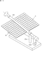
- FIG. 1 is a perspective view showing a configuration of a photovoltaic power generation apparatus according to the present embodiment, and FIG. 2 is a side view thereof.
- the solar power generation device 100 includes two plate-like arrays 1 and a support device 2 thereof.
- the array 1 is an example of a photovoltaic power generation panel according to the embodiment.
- Such an array 1 is configured by concentrating concentrating solar power generation modules 1M in a matrix on a rear frame 11.
- the support device 2 includes two support columns 21a and 21b, a base 22, a drive shaft 23, and a support shaft 24.
- the columns 21a and 21b extend in the vertical direction, the lower ends are fixed to the foundation 22, and are erected on the ground surface.
- the foundation 22 is firmly embedded in the ground so that only the upper surface is visible.
- the columns 21a and 21b are vertical.
- the two support columns 21a and 21b are arranged at a predetermined distance from each other, and both ends of the support shaft 24 are supported on the upper ends of the support columns 21a and 21b.
- the lengths of the columns 21a and 21b are different, and the column 21a is longer than the column 21b. That is, the support shaft 24 is supported by the support columns 21a and 21b in an inclined state.
- the axial direction of the support shaft 24 (second direction, hereinafter also referred to as “X direction”) can be parallel to the ground axis.
- the X direction is not limited to this.
- the X direction can be a direction within a predetermined angle range with respect to the ground axis. This angle range can be, for example, within ⁇ 5 ° with respect to the ground axis.
- the vertical direction including the ground axis hereinafter referred to as “north-south vertical plane” may be parallel.
- the X direction can be a direction within a predetermined angle range with respect to the north-south vertical plane. This angular range can be within ⁇ 5 ° with respect to the north-south vertical plane, for example.
- the X direction may not be inclined with respect to the ground surface.
- the X direction when installing the photovoltaic power generation apparatus 100 on the equator, if the X direction is parallel to the ground axis, the X direction becomes a horizontal north-south direction, and the support shaft 24 extends horizontally. Detailed setting of the support shaft 24 in the axial direction will be described later.
- the support columns 21a and 21b support the support shaft 24 in a rotatable manner.
- bearing mechanisms 25a and 25b are provided at the upper ends of the columns 21a and 21b, respectively, and both ends of the support shaft 24 are rotatably connected to the bearing mechanisms 25a and 25b.
- the bearing mechanism 25b on the column 21b side is provided with a second drive device 26b including a motor for driving the support shaft.
- the second drive device 26b can rotate the support shaft 24 around a central axis (second axis) extending in the X direction. This center axis is the rotation center axis of the support shaft 24 and does not have to coincide with the center axis of the support shaft 24.
- the drive shaft 23 is supported at the center of the support shaft 24 in the X direction.
- the axial direction of the drive shaft 23 (first direction; hereinafter also referred to as “Y direction”) is a direction orthogonal to the X direction.
- the drive shaft 23 only needs to be substantially orthogonal to the support shaft 24, and a case where the drive shaft 23 is not strictly orthogonal due to an attachment error or the like is allowed.
- the support shaft 24 supports the drive shaft 23 in a rotatable manner.
- a bearing mechanism 27 is provided at the X direction center portion of the support shaft 24, and the Y direction center portion of the drive shaft 23 is rotatably connected to the bearing mechanism 27.
- the bearing mechanism 27 is provided with a first drive device 26a including a drive shaft rotating motor.
- the first drive device 26a can rotate the drive shaft 23 around a central axis (first axis) extending in the Y direction. This central axis is the rotational central axis of the drive shaft 23 and does not have to coincide with the central axis of the drive shaft 23.
- the drive shaft 23 is fixed near the center of the flat frame-like gantry 11. Therefore, when the support shaft 24 is rotated in the circumferential direction around the axis (hereinafter referred to as “solar circulation direction”), the drive shaft 23 and the array 1 are also integrally rotated in the solar circulation direction. Further, when the drive shaft 23 rotates in the circumferential direction around the axis (hereinafter referred to as “solar altitude direction”), the array 1 also integrally rotates in the solar altitude direction.
- the support position of the drive shaft 23 on the support shaft 24 is an intermediate portion in the axial length direction of the support shaft 24. That is, the array 1 is supported by the support shaft 24 between the support columns 21a and 21b. Thereby, since the load of the array 1 is distributed to the two support columns 21a and 21b, the array 1 can be stably supported.
- the first drive device 26a can rotate the drive shaft 23 in the solar altitude direction so that the light receiving surface 1a of the array 1 faces the sun. For this reason, the angular range in which the drive shaft 23 can be rotated is ⁇ 23.4 ° or more around the angle at which the light receiving surface 1a faces the sun on the day of spring or autumn.
- the second driving device 26b can rotate the support shaft 24 by 180 ° in the solar circulation direction from a vertical posture in which the light receiving surface 1a of the array 1 is horizontally oriented toward the east side to a vertical posture in which the light receiving surface 1a is horizontally oriented toward the west side. Thereby, the sun tracking can be performed from sunrise to sunset.
- the rotation range of the array 1 in the solar altitude direction and the solar circling direction is not limited to the above. It is good also as a rotation range where the array 1 can take the horizontal attitude
- the array 1 can be placed in the above horizontal posture at night or during the cleaning operation of the light receiving surface 1a, etc., preventing the dirt and the like from adhering to the light receiving surface 1a, and the burden of the cleaning operation. Can be reduced.
- Such a horizontal posture of the array 1 is realized by combining rotation in the solar altitude direction and the solar circling direction.
- the array 1 rotates in the solar circle direction so as to pass between the columns 21 a and 21 b. That is, each of the support columns 21a and 21b is spaced apart from each other in the X direction so as to avoid contact with the array 1. Thereby, the array 1 can take a horizontal attitude
- a box 13 is provided near the lower end of the column 21a, and a control circuit (not shown) is accommodated in the box 13.
- the control circuit can control the first drive device 26a and the second drive device 26b to execute the sun tracking.
- FIG. 3 is a perspective view showing an example of the configuration of the module 1M.
- the module 1M is a concentrating solar power generation module.
- the module 1M includes, for example, a metal-made rectangular flat-bottomed container-like casing 31, and a light collecting portion 32 attached thereon like a lid.
- the light condensing unit 32 is configured, for example, by attaching a resin condensing lens 32f to the back surface of one transparent glass plate 32a.
- each of the illustrated square (10 ⁇ 14) sections is a Fresnel lens as the condensing lens 32f, and can converge sunlight to a focal position.
- a flexible printed wiring board 33 is disposed on the bottom surface 31 b of the housing 31.
- a cell package 34 that holds cells (power generation elements) is mounted at a predetermined position on the flexible printed wiring board 33.
- a part surrounded by a two-dot chain line “ ⁇ ” is an enlarged view of the light receiving part R.
- a secondary lens 35 is provided on the cell package 34, and a protective plate 36 is provided around the secondary lens 35.
- the secondary lens 35 is, for example, a ball lens.
- the protection plate 36 is, for example, an annular metal body, and a commercially available washer can be used.
- the protective plate 36 prevents the convergent light from causing thermal damage to the periphery of the cell when the convergent light of the sunlight deviates from the secondary lens 15. Further, even when all the convergent light is in the secondary lens 35, the protective plate 36 receives the scattered light in the housing 31 and reflects it.
- the light receiving portions R are provided in the same number and at the same intervals corresponding to each of the condenser lenses 32f.
- a shielding plate 37 is provided between the light receiving unit R and the light collecting unit 32.
- a square opening 37a similar to the outer diameter of one condenser lens 32f is formed at a position corresponding to each condenser lens 32f.
- the light converged by the condenser lens 32f passes through the opening 37a.
- FIG. 4 is an example of a cross-sectional view showing the minimum basic configuration of the optical system.
- the incident direction of the sunlight is perpendicular to the condenser lens 32f of the condensing unit 32, and the incident direction A S and the optical axis A X are parallel to each other (i.e., the incident direction A S and the light and the axis A X are coincident).
- the light converged by the condenser lens 32 f passes through the opening 37 a of the shielding plate 37 and enters the secondary lens 35.
- the secondary lens 35 guides the incident light to the cell 38.
- the cell 38 is held in the cell package 34.
- the protection plate 36 is attached so as to ride on the upper end of the cell package 34.
- a light-transmitting resin 39 is enclosed between the secondary lens 35 and the cell 38.
- the optical axis A X connecting the condenser lens 32f and the cell 38 meets the incident direction A S of sunlight, all light collected by the condenser lens 32f cell 38.
- the cell 38 converts most of the received light into electrical energy and outputs electric power.
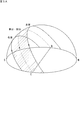
- FIG. 5A is a diagram for explaining the sun trajectory at a point of 35 degrees north latitude
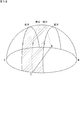
- FIG. 5B is a diagram for explaining the sun trajectory at a point on the equator.
- a virtual hemisphere centered on the point is shown above the point of interest (that is, the point where the photovoltaic power generation apparatus 100 is installed).
- the sun passes along a trajectory indicated by a broken line in the spring equinox or autumn equinox, and follows a trajectory indicated by two solid lines in the summer solstice or winter solstice.
- the range through which the sun can pass is a band-like region between two solid lines (a region indicated by diagonal lines in the figure, hereinafter referred to as “sun passage region”).
- the possible range of the incident direction of sunlight is a set of directions connecting each position of the sun passage region and the center (point of interest) of the virtual hemisphere. Therefore, if the axial length direction of the support shaft 24 coincides with the direction connecting the point of interest and an arbitrary point in the sun passage region, the axial length direction of the support shaft 24 coincides with the incident direction of sunlight. To do.
- An example is a solar power generation device disclosed in Japanese Patent Application Laid-Open No. 2007-19331.
- This solar power generation device is configured by providing a tracking drive unit for rotating the solar cell panel at the upper end of a support column extending in the vertical direction.
- the tracking drive unit includes a worm speed reducer that rotates the solar cell panel in the horizontal direction and a power cylinder that tilts (rotates) the solar cell panel in the elevation direction.
- a case where the axial length direction of the support column, that is, the rotational axis by the worm reducer coincides with the incident direction of sunlight will be considered.
- the rotational axis (hereinafter referred to as “vertical axis”) by the worm reducer extends in the vertical direction. Therefore, when the sun passes through the zenith, the vertical axis coincides with the incident direction of sunlight. At this time, as shown in FIG. 5B, the sun accurately goes up from the east, passes through the zenith, and passes along a trajectory that accurately sinks to the west.
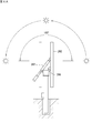
- 6A and 6B are diagrams illustrating solar tracking when the vertical axis of the photovoltaic power generation apparatus disclosed in Japanese Patent Application Laid-Open No. 2007-19331 coincides with the incident direction of sunlight.
- FIG. 6A and 6B show a state in which the solar power generation device 100 is viewed horizontally from the south side. Since the earth always rotates, the vertical axis coincides with the incident direction of sunlight in a very short time of the day. On the day when the sun passes through the zenith, the sun apparently moves in the plane including the vertical axis (vertical plane parallel to the east-west direction), and therefore, as shown in FIG. Without rotating the panel 202 around the vertical axis, that is, in the horizontal direction, the panel 202 is rotated around the axis, that is, in the elevation direction, with the axis of rotation by the power cylinder 207 orthogonal to the solar passage plane. Rotate.
- the sun tracking can be performed by rotating the panel 202 only in the elevation direction from sunrise to sunset (see FIG. 6A).
- the photovoltaic power generation apparatus disclosed in Japanese Patent Application Laid-Open No. 2007-19331 has an elevation angle of only about 90 ° from the vertical posture with the light receiving surface facing the horizontal direction to the horizontal posture with the light receiving surface facing vertically upward.
- the panel 202 cannot be rotated in the direction. For this reason, the sun tracking from the sunrise to the sunset is impossible only by the rotation of the panel 202 in the elevation direction. In this case, as shown in FIG.
- the panel 202 in the horizontal posture is rotated 180 ° in the azimuth direction in the horizontal plane by the worm speed reducer 206 at a short time when the vertical axis coincides with the incident direction of sunlight.
- the rotation direction of the elevation angle direction is reversed (hereinafter referred to as “inversion tracking”).
- inversion tracking the operation
- the concentrating solar power generation module has a characteristic that the power generation amount is substantially zero if the light receiving surface does not coincide with the incident direction of sunlight within an error range of about 1.0 °. (See FIG. 4). Therefore, when performing reversal tracking, the light receiving surface of the panel 202 cannot be directed vertically upward unless the rotation plane in the azimuth direction is exactly vertical (ie, horizontal) with respect to the vertical axis. An area that cannot be tracked (an area that cannot be tracked) occurs.
- FIG. 7 is a graph showing the simulation result.
- the vertical axis indicates the rotational angular velocity of the panel 202
- the horizontal axis indicates time.
- the angular velocity in the azimuth direction is 0 from the start of tracking (6:00) to around 11:00, and then increases rapidly.
- the angular velocity reaches a peak and then decreases rapidly.
- the angular velocity in the azimuth direction becomes 0, and after that, tracking ends (18:00) in that state.
- the peak value of the angular velocity in the azimuth direction at 12:00 was about 600 [° / hour]. Assuming that the limit rotational speed of the worm reducer 206 is 200 [° / hour], this peak value greatly exceeds the limit value. For this reason, it turns out that rotation in the azimuth direction is not in time, and a time zone in which solar tracking is impossible occurs.
- the axial length direction of the support shaft 24 can be a direction that excludes a possible range of the incident direction of sunlight. Thereby, it is not necessary to perform the reversal tracking as described above, and it is possible to prevent a non-trackable area from occurring. In this case, since it is not necessary to perform reverse tracking, the rotation angle range of the drive shaft 23 can be less than 180 °. Thereby, it is not necessary to use an expensive through drive having a large movable range in order to rotate the drive shaft 23.
- the axial direction of the support shaft 24 may be a direction within the range that the incident direction of sunlight can take. In this case, if the rotation angle range of the support shaft 24 is 180 ° or more, it is possible to perform sun tracking from sunrise to sunset without performing reverse tracking.
- the axial direction of the support shaft 24 may be a direction parallel to the north-south vertical plane.
- the sun's trajectory in one day is substantially symmetric about the north-south vertical plane. Therefore, by making the axial direction of the support shaft 24 parallel to the north-south vertical plane, rotation control around the axis of the drive shaft 23 of the array 1 and the axis of the support shaft 24 in the solar tracking is performed. It can be simplified.
- the axial length direction of the support shaft 24 may not be exactly parallel to the north-south vertical plane, and may intersect within an angle range of ⁇ 5 ° or less, for example. Thereby, manufacturing errors and mounting errors of the parts of the support device 2 are allowed. Even if the axial length direction of the support shaft 24 is not parallel to the north-south vertical plane, the rotation control of the array 1 can be simplified sufficiently if the difference is small.
- the axial direction of the support shaft 24 may be parallel to the ground axis.
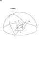
- FIG. 8 is a diagram for explaining the sun tracking when the axial length direction of the support shaft 24 is parallel to the ground axis.
- FIG. 8 shows solar tracking in the spring equinox or autumn equinox.
- the sun apparently moves on a plane that intersects perpendicularly to the earth axis (hereinafter referred to as “solar moving surface”) (see FIGS. 5A and 5B). Therefore, if the light-receiving surface 1a of the array 1 is made parallel to the support shaft 24, the sun tracking can be performed only by rotating the array 1 around the axis of the support shaft 24, that is, in the direction of solar rotation.
- the solar tracking can be performed by rotating the array 1 in the solar direction without actually rotating the array 1 in the solar altitude direction.
- the solar moving surface is located north or south compared to the solar moving surface on the equinox or autumn equinox day. Therefore, if the angle in the solar altitude direction is set so as to face the sun at that day, then the solar tracking is performed by rotating in the solar circling direction without actually rotating the array 1 in the solar altitude direction. be able to.
- the axial length direction of the support shaft 24 may not be exactly parallel to the ground axis, and may intersect within an angle range of ⁇ 5 ° or less, for example. Thereby, manufacturing errors and mounting errors of the parts of the support device 2 are allowed. Even if the axial length direction of the support shaft 24 is not parallel to the ground axis, if the difference is small, the rotation control of the array 1 can be simplified sufficiently.
- FIG. 9 is a diagram for explaining the rotation angle range of the array 1 in the solar circling direction.
- the solar power generation device 100 seen from the X direction is shown.
- a rotation angle range (“Range A” in the figure) from the posture in which at least the light-receiving surface 1a of the array 1 faces the daylight direction in the summer solstice to the posture in which it enters the sunlight direction is set in the solar circulation direction. Is done. As a result, it is possible to track the sun from Hinode to Hinode throughout the year.
- the sun rises precisely from the east in Hiji, and the sun sets precisely in the west in Hire.
- the sun rises.
- Sun tracking is possible from sunset to sunset.
- the above-mentioned range A is larger than 180 ° because the sunshine duration is longer in the northern hemisphere in summer and in the southern hemisphere in winter than in spring or autumn.
- a 360 ° rotation range is required in order to perform sun tracking continuously throughout the day in a latitude area with white night.
- the rotation angle range in the solar circling direction can be a range from the angle at which the array 1 is positioned vertically downward to the angle at which the light receiving surface 1a is oriented in the direction of the sunset on the summer solstice (in the figure).
- “Range B”), or an angle (0 °) at which the array 1 is positioned vertically downward may be set to a range of 360 ° (“range C” in the figure).
- FIG. 10A is a diagram for explaining a rotation angle range in the solar altitude direction of the array 1 at a point of 35 degrees north latitude.
- FIG. 10A shows the solar power generation device 100 viewed horizontally from the side with the drive shaft 23 in a horizontal state, that is, in a state where the Y direction coincides with the horizontal direction.
- a range of ⁇ 23.4 ° (“range a” in the figure) is set centering on the solar altitude at least in spring or autumn (55 ° north-south at 55 ° latitude). .
- the sun tracking can be performed throughout the year.
- a range of 58.4 ° from the lower limit angle of the above range a that is, the solar altitude at the winter solstice; 31.6 ° at a point of 35 ° north latitude
- range b the range of 58.4 ° from the lower limit angle of the above range a (that is, the solar altitude at the winter solstice; 31.6 ° at a point of 35 ° north latitude) to the angle at which the light receiving surface 1a is parallel to the north-south direction.
- Range b in the figure
- the range may be 90 ° (“range c” in the figure).
- FIG. 10B is a diagram for explaining a rotation angle range in the solar altitude direction of the array 1 at a point on the equator.
- the rotation angle range of the solar altitude direction of the array 1 is an angle (90 °) parallel to the north-south direction.
- ⁇ 23.4 ° range “a ′” in the figure.
- a larger rotation angle range including this range can also be set.
- a range of ⁇ 45 ° centering on an angle parallel to the north-south direction can be set (range “c ′” in the figure).
- the rotation angle range in the solar circling direction is a range including an angle for positioning the array 1 vertically downward
- the rotation angle range in the solar altitude direction is set so that the light receiving surface 1a of the array 1 is parallel to the north-south direction.
- the light-receiving surface 1a can be faced vertically downward. That is, the light receiving surface 1a can be directed vertically downward by making the light receiving surface 1a parallel to the north-south direction and positioning the array 1 vertically downward.
- the array 1 take a horizontal posture, it is possible to prevent dirt and the like from adhering to the light receiving surface 1a and to reduce the burden of cleaning work.
- FIG. 11 is a perspective view illustrating a configuration of a photovoltaic power generation apparatus according to a modification of the embodiment.
- the photovoltaic power generation apparatus according to this modification supports the middle of the support shaft 224 that is longer than the distance between adjacent columns 221a and 221b at the upper ends of the columns 221a and 221b. That is, the support shaft 224 extends on both outer sides of the range between the columns 221a and 221b.
- the drive shaft 23 is supported on a portion of the support shaft 224 that extends outward from the support column 221a. That is, the support position of the drive shaft 23 on the support shaft 224 is not between the support columns 221a and 221b but outside the support column 221a.
- the array 1 rotates in the solar circulation direction outside the support column 221a.
- the column 221a is arranged so as to avoid contact with the array 1.
- the array 1 can take a vertical attitude
- the configuration in which the support shaft 24 rotates about the axis is described, but the present invention is not limited to this.
- the support shaft 24 may be fixedly supported by the support columns 21 a and 21 b, and only the fixed portion of the drive shaft 23 in the support shaft 24 may be rotatable around the axis of the support shaft 24.
- the drive shaft 23 may not be rotated around the axis, but only the fixed portion of the mount 11 of the drive shaft 23 can be rotated around the axis of the drive shaft 23.
- the module 1M is not limited to the concentrating solar power generation module, and may be a crystalline silicon solar power generation module.
Landscapes
- Life Sciences & Earth Sciences (AREA)
- Sustainable Development (AREA)
- Photovoltaic Devices (AREA)
Abstract
La présente invention concerne un générateur d'énergie solaire comprenant : un panneau de génération d'énergie solaire ayant une surface de réception de lumière, le panneau de génération d'énergie solaire étant apte à tourner autour d'un premier axe qui s'étend dans une première direction parallèle à la surface de réception de lumière ; un arbre de support s'étendant dans une seconde direction qui croise la première direction, l'arbre de support supportant le panneau de génération d'énergie solaire de façon à pouvoir tourner autour d'un second axe qui s'étend dans la seconde direction ; et une pluralité de colonnes de support installées sur une surface de sol, la pluralité de colonnes de support supportant l'arbre de support au niveau de chacun des emplacements d'une pluralité d'emplacements séparés dans la seconde direction. Les colonnes de support sont disposées dans des positions évitant le contact avec le panneau de génération d'énergie solaire lorsque le panneau de génération d'énergie solaire est dans une orientation faisant face à la surface de réception de lumière dans la direction horizontale.
Applications Claiming Priority (2)
| Application Number | Priority Date | Filing Date | Title |
|---|---|---|---|
| JP2018072985 | 2018-04-05 | ||
| JP2018-072985 | 2018-04-05 |
Publications (1)
| Publication Number | Publication Date |
|---|---|
| WO2019193996A1 true WO2019193996A1 (fr) | 2019-10-10 |
Family
ID=68100587
Family Applications (1)
| Application Number | Title | Priority Date | Filing Date |
|---|---|---|---|
| PCT/JP2019/012231 Ceased WO2019193996A1 (fr) | 2018-04-05 | 2019-03-22 | Générateur d'énergie solaire |
Country Status (2)
| Country | Link |
|---|---|
| TW (1) | TW201944015A (fr) |
| WO (1) | WO2019193996A1 (fr) |
Cited By (1)
| Publication number | Priority date | Publication date | Assignee | Title |
|---|---|---|---|---|
| JP7610887B1 (ja) | 2024-04-05 | 2025-01-09 | 恒栄電設株式会社 | 浮遊式太陽光発電装置および浮遊式太陽光発電システム |
Citations (3)
| Publication number | Priority date | Publication date | Assignee | Title |
|---|---|---|---|---|
| JP2003324210A (ja) * | 2002-04-30 | 2003-11-14 | Yoshitaka Karasawa | パネル分割型、太陽追尾式ソーラーパネルシステム |
| JP2004153202A (ja) * | 2002-11-01 | 2004-05-27 | Daido Steel Co Ltd | 集光式太陽光発電装置 |
| JP2013021287A (ja) * | 2011-07-08 | 2013-01-31 | Topper Sun Energy Technology Co Ltd | 太陽追尾機能を有するソーラー発電装置 |
-
2019
- 2019-03-22 WO PCT/JP2019/012231 patent/WO2019193996A1/fr not_active Ceased
- 2019-04-02 TW TW108111618A patent/TW201944015A/zh unknown
Patent Citations (3)
| Publication number | Priority date | Publication date | Assignee | Title |
|---|---|---|---|---|
| JP2003324210A (ja) * | 2002-04-30 | 2003-11-14 | Yoshitaka Karasawa | パネル分割型、太陽追尾式ソーラーパネルシステム |
| JP2004153202A (ja) * | 2002-11-01 | 2004-05-27 | Daido Steel Co Ltd | 集光式太陽光発電装置 |
| JP2013021287A (ja) * | 2011-07-08 | 2013-01-31 | Topper Sun Energy Technology Co Ltd | 太陽追尾機能を有するソーラー発電装置 |
Cited By (1)
| Publication number | Priority date | Publication date | Assignee | Title |
|---|---|---|---|---|
| JP7610887B1 (ja) | 2024-04-05 | 2025-01-09 | 恒栄電設株式会社 | 浮遊式太陽光発電装置および浮遊式太陽光発電システム |
Also Published As
| Publication number | Publication date |
|---|---|
| TW201944015A (zh) | 2019-11-16 |
Similar Documents
| Publication | Publication Date | Title |
|---|---|---|
| JP5569447B2 (ja) | 太陽光発電装置 | |
| US7923624B2 (en) | Solar concentrator system | |
| CN101359884B (zh) | 地面太阳能阵列 | |
| KR101162844B1 (ko) | 태양광 발전 장치 | |
| KR100961248B1 (ko) | 태양추적형 태양광 발전장치 | |
| US9660122B2 (en) | Compact LCPV solar electric generator | |
| KR20080109754A (ko) | 추적 태양 전력 시스템 | |
| US20090084375A1 (en) | Aligned multiple flat mirror reflector array for concentrating sunlight onto a solar cell | |
| JP5089474B2 (ja) | 追尾集光型太陽電池装置 | |
| WO2009049454A1 (fr) | Dispositif de génération d'énergie photovoltaïque, du type à huit diagrammes taichi, doté de contrepoids | |
| WO2010034038A2 (fr) | Systèmes et procédés de captage d'énergie solaire comprenant des caractéristiques de configuration et/ou de suivi | |
| TW201707373A (zh) | 聚光型太陽光發電單元、聚光型太陽光發電模組、聚光型太陽光發電面板及聚光型太陽光發電裝置 | |
| US20100108121A1 (en) | Concentrating solar cell module | |
| KR20110133759A (ko) | 2축 추적식 태양광 발전 장치 | |
| CN103208947B (zh) | 一种屋顶太阳能聚光发电系统 | |
| EP3018822B1 (fr) | Réseau de cellules solaires à micro-concentrateur utilisant des réflecteurs basés sur des systèmes micro-électromécaniques (mems) | |
| WO2019193996A1 (fr) | Générateur d'énergie solaire | |
| CN202872691U (zh) | 一种屋顶太阳能聚光发电系统 | |
| CN103149946A (zh) | 阵列式镜组定向反射控制系统 | |
| KR20090113797A (ko) | 일사량 변화에 따른 태양광 발전장치 및 그 방법 | |
| RU2740437C1 (ru) | Концентраторная солнечная энергетическая установка | |
| KR20140015805A (ko) | 태양광 발전장치 | |
| CN102072562A (zh) | 太阳能装置 | |
| KR101191456B1 (ko) | 태양광 추적 장치 | |
| KR101202382B1 (ko) | 태양광 집광장치 |
Legal Events
| Date | Code | Title | Description |
|---|---|---|---|
| 121 | Ep: the epo has been informed by wipo that ep was designated in this application |
Ref document number: 19781842 Country of ref document: EP Kind code of ref document: A1 |
|
| NENP | Non-entry into the national phase |
Ref country code: DE |
|
| 122 | Ep: pct application non-entry in european phase |
Ref document number: 19781842 Country of ref document: EP Kind code of ref document: A1 |
|
| NENP | Non-entry into the national phase |
Ref country code: JP |