WO2019198464A1 - Moteur et moteur d'essuie-glace sans balai - Google Patents
Moteur et moteur d'essuie-glace sans balai Download PDFInfo
- Publication number
- WO2019198464A1 WO2019198464A1 PCT/JP2019/012074 JP2019012074W WO2019198464A1 WO 2019198464 A1 WO2019198464 A1 WO 2019198464A1 JP 2019012074 W JP2019012074 W JP 2019012074W WO 2019198464 A1 WO2019198464 A1 WO 2019198464A1
- Authority
- WO
- WIPO (PCT)
- Prior art keywords
- permanent magnet
- salient pole
- motor
- rotor
- circumferential
- Prior art date
- Legal status (The legal status is an assumption and is not a legal conclusion. Google has not performed a legal analysis and makes no representation as to the accuracy of the status listed.)
- Ceased
Links
Images

Classifications
-
- H—ELECTRICITY
- H02—GENERATION; CONVERSION OR DISTRIBUTION OF ELECTRIC POWER
- H02K—DYNAMO-ELECTRIC MACHINES
- H02K1/00—Details of the magnetic circuit
- H02K1/06—Details of the magnetic circuit characterised by the shape, form or construction
- H02K1/22—Rotating parts of the magnetic circuit
- H02K1/27—Rotor cores with permanent magnets
- H02K1/2706—Inner rotors
- H02K1/272—Inner rotors the magnetisation axis of the magnets being perpendicular to the rotor axis
- H02K1/274—Inner rotors the magnetisation axis of the magnets being perpendicular to the rotor axis the rotor consisting of two or more circumferentially positioned magnets
- H02K1/2753—Inner rotors the magnetisation axis of the magnets being perpendicular to the rotor axis the rotor consisting of two or more circumferentially positioned magnets the rotor consisting of magnets or groups of magnets arranged with alternating polarity
- H02K1/278—Surface mounted magnets; Inset magnets
-
- B—PERFORMING OPERATIONS; TRANSPORTING
- B60—VEHICLES IN GENERAL
- B60S—SERVICING, CLEANING, REPAIRING, SUPPORTING, LIFTING, OR MANOEUVRING OF VEHICLES, NOT OTHERWISE PROVIDED FOR
- B60S1/00—Cleaning of vehicles
- B60S1/02—Cleaning windscreens, windows or optical devices
- B60S1/04—Wipers or the like, e.g. scrapers
- B60S1/06—Wipers or the like, e.g. scrapers characterised by the drive
- B60S1/08—Wipers or the like, e.g. scrapers characterised by the drive electrically driven
-
- H—ELECTRICITY
- H02—GENERATION; CONVERSION OR DISTRIBUTION OF ELECTRIC POWER
- H02K—DYNAMO-ELECTRIC MACHINES
- H02K21/00—Synchronous motors having permanent magnets; Synchronous generators having permanent magnets
- H02K21/12—Synchronous motors having permanent magnets; Synchronous generators having permanent magnets with stationary armatures and rotating magnets
- H02K21/14—Synchronous motors having permanent magnets; Synchronous generators having permanent magnets with stationary armatures and rotating magnets with magnets rotating within the armatures
- H02K21/16—Synchronous motors having permanent magnets; Synchronous generators having permanent magnets with stationary armatures and rotating magnets with magnets rotating within the armatures having annular armature cores with salient poles
-
- H—ELECTRICITY
- H02—GENERATION; CONVERSION OR DISTRIBUTION OF ELECTRIC POWER
- H02K—DYNAMO-ELECTRIC MACHINES
- H02K7/00—Arrangements for handling mechanical energy structurally associated with dynamo-electric machines, e.g. structural association with mechanical driving motors or auxiliary dynamo-electric machines
- H02K7/10—Structural association with clutches, brakes, gears, pulleys or mechanical starters
- H02K7/116—Structural association with clutches, brakes, gears, pulleys or mechanical starters with gears
- H02K7/1163—Structural association with clutches, brakes, gears, pulleys or mechanical starters with gears where at least two gears have non-parallel axes without having orbital motion
- H02K7/1166—Structural association with clutches, brakes, gears, pulleys or mechanical starters with gears where at least two gears have non-parallel axes without having orbital motion comprising worm and worm-wheel
-
- H—ELECTRICITY
- H02—GENERATION; CONVERSION OR DISTRIBUTION OF ELECTRIC POWER
- H02K—DYNAMO-ELECTRIC MACHINES
- H02K2213/00—Specific aspects, not otherwise provided for and not covered by codes H02K2201/00 - H02K2211/00
- H02K2213/03—Machines characterised by numerical values, ranges, mathematical expressions or similar information
-
- H—ELECTRICITY
- H02—GENERATION; CONVERSION OR DISTRIBUTION OF ELECTRIC POWER
- H02K—DYNAMO-ELECTRIC MACHINES
- H02K29/00—Motors or generators having non-mechanical commutating devices, e.g. discharge tubes or semiconductor devices
- H02K29/03—Motors or generators having non-mechanical commutating devices, e.g. discharge tubes or semiconductor devices with a magnetic circuit specially adapted for avoiding torque ripples or self-starting problems
-
- H—ELECTRICITY
- H02—GENERATION; CONVERSION OR DISTRIBUTION OF ELECTRIC POWER
- H02K—DYNAMO-ELECTRIC MACHINES
- H02K5/00—Casings; Enclosures; Supports
- H02K5/04—Casings or enclosures characterised by the shape, form or construction thereof
- H02K5/16—Means for supporting bearings, e.g. insulating supports or means for fitting bearings in the bearing-shields
- H02K5/163—Means for supporting bearings, e.g. insulating supports or means for fitting bearings in the bearing-shields radially supporting the rotary shaft at only one end of the rotor
Definitions
- the present invention relates to a motor and a brushless wiper motor.
- a brushless motor (hereinafter sometimes simply referred to as a motor) includes a stator having teeth around which a coil is wound, and a rotor that is rotatably provided on the radial inner side of the stator. Slots are formed between adjacent teeth in the circumferential direction. A coil is wound around each tooth through this slot. An interlinkage magnetic flux is formed in the stator by supplying power to the coil.
- the rotor includes a shaft, a substantially columnar rotor core that is fitted and fixed to the shaft, and a permanent magnet provided on the rotor core. For example, a ferrite magnet is used as the permanent magnet. Then, a magnetic attractive force or a repulsive force is generated between the interlinkage magnetic flux formed in the stator and the permanent magnet provided in the rotor core, and the rotor continuously rotates.
- a rotor having a salient pole protruding outward in the radial direction between permanent magnets adjacent in the circumferential direction on the outer peripheral surface of the rotor core has been proposed (for example, see Patent Document 1).
- a direction in which the interlinkage magnetic flux (q-axis magnetic flux) due to the stator coil easily flows and a direction in which the interlinkage magnetic flux hardly flows (d-axis direction) are formed.
- reluctance torque is generated in the rotor core, and this reluctance torque can also contribute to the rotational force of the rotor.
- the ratio of the number of magnetic poles to the number of teeth (number of slots) is 2: 3.
- the present invention provides a motor and a brushless that can prevent the rotor core from stopping at the rotation angle at which the permanent magnet is most likely to demagnetize when the ratio of the number of magnetic poles of the permanent magnet to the number of teeth is 2: 3.
- a wiper motor is provided.
- a motor according to the present invention is wound around a tooth having an annular stator core, a stator having a plurality of teeth projecting radially inward from an inner peripheral surface of the stator core, and A coil rotating on the radially inner side of the stator core, a rotor core fixed to the shaft and having a rotational axis of the shaft as a radial center, and an outer peripheral surface of the rotor core, wherein the orientation of magnetization is A plurality of permanent magnets in parallel orientation and the permanent magnets adjacent in the circumferential direction of the outer peripheral surface of the rotor core are formed to protrude outward in the radial direction, and the circumferential side surfaces of the permanent magnet are in contact with each other.
- the ratio of the number of magnetic poles of the permanent magnet to the number of teeth is 2: 3, and the permanent magnet is provided on the circumferential side surface of the permanent magnet.
- An inclined surface formed so as to be gradually separated from the salient pole is formed toward the outer peripheral surface of the outer side in the radial direction, and the rotation axis is connected to a corner where the inclined surface and the outer peripheral surface are connected.
- the angle between the straight line and the straight line connecting the outermost radial direction on the circumferential side surface of the salient pole and the rotation axis is an electrical angle of 13 ° or more.
- the permanent magnet is a ferrite magnet.
- the inclined surface of the permanent magnet is parallel to a straight line connecting a circumferential center of the permanent magnet and the rotation axis.
- Such a configuration can facilitate the production of the permanent magnet and reduce the cost of the permanent magnet. Moreover, since the circumferential direction both side surfaces of a permanent magnet become parallel, the circumferential direction both side surfaces of a salient pole also become parallel. For this reason, the saturation of the magnetic flux which flows through a salient pole can be suppressed compared with the case where a salient pole is trapezoid seeing from a rotation axis direction, for example.
- the motor according to the present invention is characterized in that a circumferential width dimension at the radially outer end of the salient pole is 40 ° or less in electrical angle.
- the inductance value in the q-axis direction can be reduced, and the demagnetizing field can be suppressed. Can do.
- a circumferential width dimension at the radially outer end of the salient pole is 20 ° or more in electrical angle.
- the magnetic field concentrates on the salient pole so that the demagnetizing field hardly acts on the end of the permanent magnet.
- the effect of becoming can be obtained with certainty.
- a high reluctance torque can be obtained by setting the electrical angle of the salient pole to 20 ° or more and 40 ° or less.
- one groove portion is formed on the radially outer end face of the salient pole along the rotational axis direction, and the groove width gradually increases in the circumferential direction toward the radially inner side. It is characterized by being formed so as to be narrow.
- the gap between the end face and the teeth can be non-uniform when viewed on the entire radially outer end face of the salient pole. it can.
- it is possible to suppress a rapid change in the magnetic flux density generated in the teeth before and after the salient pole passes between the teeth during the rotation of the rotor core. For this reason, the rapid torque fluctuation of the rotor core can be reduced, and the torque ripple can be reduced.
- a brushless wiper motor according to the present invention includes the motor described above.
- a brushless wiper motor can be provided.
- the order of the cogging torque is increased more than usual even in a motor having salient poles. Can be prevented. For this reason, it is possible to prevent the rotor core from stopping at the rotation angle at which the permanent magnet is most likely to demagnetize.
- FIG. 2 is a cross-sectional view taken along line AA in FIG.
- FIG. 6 is a block diagram of the stator and rotor in embodiment of this invention.
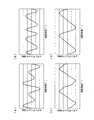
- FIG. 6 is a graph showing a change in cogging torque in the embodiment of the present invention, wherein (a) to (d) change the electrical angle of the inclined surface formed in the permanent magnet.
- It is a graph which shows the q axis
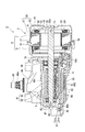
- FIG. 1 is a perspective view of the wiper motor 1.
- FIG. 2 is a cross-sectional view taken along line AA in FIG.
- the wiper motor 1 serves as a drive source for a wiper mounted on a vehicle, for example.
- the wiper motor 1 includes a motor unit 2, a deceleration unit 3 that decelerates and outputs the rotation of the motor unit 2, and a controller unit 4 that performs drive control of the motor unit 2.
- the axial direction simply refers to the rotational axis direction of the shaft 31 of the motor unit 2
- the simple circumferential direction refers to the circumferential direction of the shaft 31
- the simple radial direction refers to the shaft.
- the radial direction of 31 shall be said.
- the motor unit 2 includes a motor case 5, a substantially cylindrical stator 8 housed in the motor case 5, and a rotor 9 provided on the radially inner side of the stator 8 and rotatable with respect to the stator 8. And.
- the motor unit 2 is a so-called brushless motor that does not require a brush when supplying power to the stator 8.
- the motor case 5 is formed of a material having excellent heat dissipation, such as aluminum die casting.
- the motor case 5 includes a first motor case 6 and a second motor case 7 that are configured to be separable in the axial direction.
- the first motor case 6 and the second motor case 7 are each formed in a bottomed cylindrical shape.
- the first motor case 6 is integrally formed with the gear case 40 so that the bottom 10 is joined to the gear case 40 of the speed reduction unit 3.
- a through-hole 10a through which the shaft 31 of the rotor 9 can be inserted is formed at a substantially central portion of the bottom portion 10 in the radial direction.
- an outer flange portion 16 that projects outward in the radial direction is formed in the opening 6 a of the first motor case 6, and is stretched outward in the radial direction in the opening 7 a of the second motor case 7.
- An outer flange portion 17 is formed.
- a motor case 5 having an internal space is formed by abutting these outer flange portions 16 and 17 together.
- a stator 8 is disposed in the internal space of the motor case 5 so as to be fitted into the first motor case 6 and the second motor case 7.
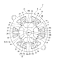
- FIG. 3 shows the configuration of the stator 8 and the rotor 9 and corresponds to a view seen from the axial direction.
- the stator 8 includes a cylindrical core portion 21 whose cross-sectional shape along the radial direction is substantially circular, and a plurality of (for example, a main body) projecting radially inward from the core portion 21.
- teeth 22 and a stator core 20 are integrally formed.
- the stator core 20 is formed by laminating a plurality of metal plates in the axial direction.
- the stator core 20 is not limited to the case where a plurality of metal plates are laminated in the axial direction, and may be formed, for example, by press-molding soft magnetic powder.
- the teeth 22 are formed by integrally forming a teeth main body 101 projecting along the radial direction from the inner peripheral surface of the core portion 21 and a flange 102 extending along the circumferential direction from the radial inner end of the teeth main body 101. It is.
- the flange portion 102 is formed so as to extend from the teeth body 101 to both sides in the circumferential direction.
- the slot 19 is formed between the collar parts 102 adjacent in the circumferential direction.
- each of the teeth 22 is covered with a resin insulator 23.
- a coil 24 is wound around each of the teeth 22 from above the insulator 23.
- Each coil 24 generates a magnetic field for rotating the rotor 9 by power feeding from the controller unit 4.
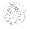
- FIG. 4 is an enlarged view of a portion A in FIG.
- the rotor 9 is rotatably provided on the radially inner side of the stator 8 through a minute gap.
- the rotor 9 has a substantially cylindrical shape with a shaft 31 integrally formed with a worm shaft 44 (see FIG. 2) constituting the speed reduction portion 3 and an outer fitting and fixing to the shaft 31 and having the shaft 31 as an axis (rotation axis) C1.
- the rotor core 32 and four permanent magnets 33 provided on the outer peripheral surface 32b of the rotor core 32 are provided.
- the permanent magnet 33 it is preferable to use a ferrite magnet.
- the ratio between the number of magnetic poles of the permanent magnet 33 and the number of slots 19 (teeth 22) is 2: 3.
- the rotor core 32 is formed by laminating a plurality of metal plates in the axial direction.
- the rotor core 32 is not limited to the case where a plurality of metal plates are laminated in the axial direction, and may be formed, for example, by press-molding soft magnetic powder.
- a through hole 32 a penetrating in the axial direction is formed at a substantially central portion in the radial direction of the rotor core 32.
- the shaft 31 is press-fitted into the through hole 32a.
- the shaft 31 may be inserted into the through hole 32a, and the rotor core 32 may be externally fixed to the shaft 31 using an adhesive or the like.
- salient poles 35 are provided on the outer peripheral surface 32b of the rotor core 32 at equal intervals in the circumferential direction.
- the salient poles 35 are formed so as to protrude outward in the radial direction and extend in the entire axial direction of the rotor core 32.
- Round chamfered portions 35 a are formed at the corners on the radially outer side of the salient poles 35 and on both sides in the circumferential direction.
- the salient pole 35 has a circumferential width dimension at the radially outer end 35t of 20 ° or more and 40 ° or less in electrical angle ⁇ .
- the circumferential width dimension at the radially outer end 35t of the salient pole 35 refers to both circumferential corners 35b (hereinafter referred to as salient poles) when the salient pole 35 is not formed with a round chamfer 35a. (Referred to as a radial corner 35b).
- the circumferential width dimension at the radially outer end 35t of the salient pole 35 will be simply referred to as the circumferential width dimension of the salient pole 35.
- the salient pole 35 is formed so that both side surfaces 35c opposed in the circumferential direction are parallel to each other. That is, the salient pole 35 is formed so that the circumferential width dimension is uniform in the radial direction. Furthermore, one groove portion 91 is formed in the axially outer end portion 35t of the salient pole 35 at substantially the center in the circumferential direction over the entire axial direction. The groove portion 91 is formed in a substantially V-groove shape so that the groove width in the circumferential direction gradually narrows toward the inner side in the radial direction.
- the outer peripheral surface 32b of the rotor core 32 formed in this way is configured as a magnet storage portion 36 between two salient poles 35 adjacent in the circumferential direction.
- Permanent magnets 33 are disposed in these magnet storage portions 36 and are fixed to the rotor core 32 by, for example, an adhesive.
- the arc center Co of the outer circumferential surface 33a on the radially outer side and the arc center Ci of the inner circumferential surface 33b on the radially inner side coincide with the position of the axis C1 of the shaft 31.
- the diameter of the circle passing through the end portion 35 t of the salient pole 35 is the same as the diameter of the outer peripheral surface 33 a of the permanent magnet 33.
- the entire inner peripheral surface 33 b of the permanent magnet 33 is in contact with the outer peripheral surface 32 b of the rotor core 32. Further, both side surfaces in the circumferential direction of the permanent magnet 33 are located on the radially inner side, a salient pole contact surface 33d that is in contact with the side surface 35c of the salient pole 35, and a radially outer side than the salient pole contact surface 33d.
- the inclined surface 33e located is smoothly connected.
- the salient pole contact surface 33d is smoothly connected to the inner peripheral surface 33b via the arc surface 33g.
- the inclined surface 33e is formed so as to be inclined and flat so as to gradually move away from the salient pole 35 as it goes from the radially outer end of the salient pole contact surface 33d toward the outer peripheral surface 33a of the permanent magnet 33.
- the inclined surfaces 33 e on both sides in the circumferential direction are parallel to a straight line L ⁇ b> 1 connecting the circumferential intermediate portion 33 c of the permanent magnet 33 and the axis C ⁇ b> 1 of the shaft 31. For this reason, the two inclined surfaces 33e are also parallel to each other.
- the shaft 31 has an outer peripheral corner 33f to which the straight line L2 connecting the radial corner 35b of the salient pole 35 and the axis C1 of the shaft 31, the inclined surface 33e of the permanent magnet 33 and the outer peripheral surface 33a are connected.
- the angle ⁇ 2 between the straight line L3 connecting the axis C1 and the electrical angle is 13 ° or more. In the following description, the angle ⁇ 2 will be described as the electrical angle ⁇ 2 of the inclined surface 33e.
- the permanent magnet 33 is magnetized so that the magnetization (magnetic field) is oriented in parallel along the thickness direction. And the permanent magnet 33 is arrange
- the speed reduction unit 3 includes a gear case 40 to which the motor case 5 is attached, and a worm speed reduction mechanism 41 accommodated in the gear case 40.
- the gear case 40 is made of a material with excellent heat dissipation, such as aluminum die cast.
- the gear case 40 is formed in a box shape having an opening 40a on one surface, and has a gear housing portion 42 for housing the worm reduction mechanism 41 therein.
- the side wall 40b of the gear case 40 is formed with an opening 43 that communicates the through hole 10a of the first motor case 6 and the gear housing portion 42 at a location where the first motor case 6 is integrally formed. Yes.
- a substantially cylindrical bearing boss 49 projects from the bottom wall 40c of the gear case 40.
- the bearing boss 49 is for rotatably supporting the output shaft 48 of the worm reduction mechanism 41, and a sliding bearing (not shown) is provided on the inner peripheral surface. Further, an O-ring (not shown) is mounted on the inner peripheral edge of the bearing boss 49. This prevents dust and water from entering from the outside to the inside via the bearing boss 49.
- a plurality of ribs 52 are provided on the outer peripheral surface of the bearing boss 49. Thereby, the rigidity of the bearing boss 49 is ensured.
- the worm speed reduction mechanism 41 accommodated in the gear accommodating portion 42 includes a worm shaft 44 and a worm wheel 45 engaged with the worm shaft 44.
- the worm shaft 44 is disposed coaxially with the shaft 31 of the motor unit 2.
- the worm shaft 44 is rotatably supported by bearings 46 and 47 provided on the gear case 40 at both ends.
- the end of the worm shaft 44 on the motor unit 2 side protrudes to the opening 43 of the gear case 40 through the bearing 46.
- the protruding end portion of the worm shaft 44 and the end portion of the shaft 31 of the motor unit 2 are joined, and the worm shaft 44 and the shaft 31 are integrated.
- the worm shaft 44 and the shaft 31 may be integrally formed by molding a worm shaft portion and a shaft portion from one base material.
- the worm wheel 45 meshed with the worm shaft 44 is provided with an output shaft 48 at the radial center of the worm wheel 45.
- the output shaft 48 is arranged coaxially with the rotational axis direction of the worm wheel 45, and protrudes to the outside of the gear case 40 via the bearing boss 49 of the gear case 40.
- a spline 48 a that can be connected to an electrical component (not shown) is formed at the protruding tip of the output shaft 48.
- a sensor magnet (not shown) is provided at the radial center of the worm wheel 45 on the side opposite to the side from which the output shaft 48 is projected.
- This sensor magnet constitutes one of the rotational position detector 60 that detects the rotational position of the worm wheel 45.
- the magnetic detection element 61 that constitutes the other of the rotational position detection unit 60 is provided in the controller unit 4 that is disposed facing the worm wheel 45 on the sensor magnet side of the worm wheel 45 (on the opening 40a side of the gear case 40). Yes.
- the controller unit 4 that controls the drive of the motor unit 2 includes a controller board 62 on which the magnetic detection element 61 is mounted, and a cover 63 provided so as to close the opening 40a of the gear case 40.
- the controller board 62 is disposed opposite to the sensor magnet side of the worm wheel 45 (opening 40a side of the gear case 40).
- the controller board 62 is obtained by forming a plurality of conductive patterns (not shown) on a so-called epoxy board.
- the controller board 62 is connected to a terminal portion of the coil 24 drawn from the stator core 20 of the motor unit 2 and electrically connected to a terminal (not shown) of the connector 11 provided on the cover 63.
- a power module (not shown) including a switching element such as a FET (Field Effect Transistor) that controls a current supplied to the coil 24 is mounted on the controller board 62.
- a capacitor (not shown) for smoothing the voltage applied to the controller board 62 is mounted on the controller board 62.
- the cover 63 covering the controller board 62 configured in this manner is formed of resin.
- the cover 63 is formed so as to bulge slightly outward.
- the inner surface side of the cover 63 is a controller housing portion 56 that houses the controller board 62 and the like.
- the connector 11 is integrally formed on the outer periphery of the cover 63. This connector 11 is formed so as to be able to be fitted with a connector 11 extending from an external power source (not shown).
- the controller board 62 is electrically connected to the terminals of the connector 11. As a result, the power of the external power supply is supplied to the controller board 62.
- a fitting portion 81 is formed on the opening edge of the cover 63 so as to be fitted with the end portion of the side wall 40 b of the gear case 40.
- the fitting portion 81 is configured by two walls 81 a and 81 b along the opening edge of the cover 63. And the edge part of the side wall 40b of the gear case 40 is inserted (fitted) between these two walls 81a and 81b.
- a labyrinth portion 83 is formed between the gear case 40 and the cover 63.
- the labyrinth 83 prevents dust and water from entering between the gear case 40 and the cover 63.
- the gear case 40 and the cover 63 are fixed by fastening a bolt (not shown).
- the wiper motor 1 Next, the operation of the wiper motor 1 will be described.
- the power supplied to the controller board 62 via the connector 11 is selectively supplied to each coil 24 of the motor unit 2 via a power module (not shown).
- a predetermined flux linkage is formed in the stator 8 (tooth 22), and a magnetic attractive force or repulsive force is generated between the flux linkage and an effective magnetic flux formed by the permanent magnet 33 of the rotor 9.
- the rotor 9 rotates continuously.
- the rotation position detection result of the worm wheel 45 detected by the magnetic detection element 61 mounted on the controller board 62 is output as a signal to an external device (not shown).
- the external device controls the switching timing of the switching elements and the like of the power module (not shown) based on the rotational position detection signal of the worm wheel 45, and the drive control of the motor unit 2 is performed.
- the output of the drive signal of the power module and the drive control of the motor unit 2 may be performed by the controller unit 4.
- the rotor 9 is a so-called SPM (Surface Permanent Magnet) type rotor in which a permanent magnet 33 is disposed on the outer peripheral surface 32 b of the rotor core 32. For this reason, the inductance value in the d-axis direction can be reduced.
- the rotor 9 is provided with salient poles 35 between the permanent magnets 33 adjacent in the circumferential direction. As a result, the inductance value in the q-axis direction due to the interlinkage magnetic flux of the stator 8 can be increased as compared with the case where the salient pole 35 is not provided. Therefore, the rotor 9 is rotated using the difference in reluctance torque between the d-axis direction and the q-axis direction.
- the reciprocity torque can contribute to the rotational torque of the rotor 9, and the interlinkage magnetic flux of the stator 8 can easily pass through both side surfaces of the permanent magnet 33 in contact with the salient poles 35. For this reason, a demagnetizing field of the permanent magnet 33 due to the interlinkage magnetic flux is generated on both circumferential sides of the permanent magnet 33. Further, by providing the salient pole 35, the magnetic flux of the permanent magnet 33 flows through the salient pole 35. For this reason, there is a possibility that the order of the cogging torque of the motor unit 2 is increased by the magnetic flux formed on the salient poles 35 than the number of magnetic poles of the rotor 9 (four poles in this embodiment).
- FIG. 5 is a graph showing changes in cogging torque when the vertical axis is the cogging torque [mNm] of the rotor 9 and the horizontal axis is the rotation angle of the rotor 9, and (a) is an inclined surface of the permanent magnet 33.
- the electrical angle ⁇ 2 of 33e is 5 °
- (b) is when the electrical angle ⁇ 2 of the inclined surface 33e of the permanent magnet 33 is 10 °
- (c) is the electrical angle of the inclined surface 33e of the permanent magnet 33.
- ⁇ 2 is 13 °
- (d) shows the case where the electrical angle ⁇ 2 of the inclined surface 33e of the permanent magnet 33 is 15 °.
- the number of peaks is the order of the cogging torque.
- the ratio between the number of magnetic poles of the permanent magnet 33 and the number of slots 19 (teeth 22) is 2: 3.
- the electrical angle ⁇ 2 of the inclined surface 33e of the permanent magnet 33 is 13
- the angle is possible to prevent the order of the cogging torque from increasing more than the number of magnetic poles of the rotor 9.
- the rotor core 32 is stopped at the rotation angle at which the permanent magnet 33 is most likely to demagnetize.
- the magnetization direction of the permanent magnet 33 is parallel orientation, cogging of the motor unit 2 can be suppressed and a high magnetic flux density can be obtained.
- the salient pole 35 of the rotor 9 is formed with a groove 91 at the end 35t.
- interval of this edge part 35t and the teeth 22 (hook part 102) of the stator 8 can be made non-uniform
- the salient poles 35 of the rotor core 32 are formed so that the circumferential width dimension is 20 ° or more and 40 ° or less in terms of the electrical angle ⁇ 1.
- the inductance value in the q-axis direction can be reduced by setting the circumferential width dimension of the salient pole 35 to 40 ° or less in terms of the electrical angle ⁇ 1.
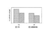
- FIG. 6 is a graph showing the inductances Lq and Ld [mH] of the q-axis and d-axis of the rotor 9, and the rotor 9 of the present embodiment is compared with the rotor of the conventional structure.
- the conventional structure here is the structure of a rotor of a so-called IPM (Interior Permanent Magnet) motor in which permanent magnets are arranged in a plurality of slits formed in the rotor core.
- IPM Interior Permanent Magnet
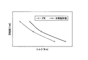
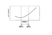
- FIG. 7 is a graph showing changes in the rotational speed of the rotor 9 when the vertical axis is the rotational speed [rpm] of the rotor 9 and the horizontal axis is the torque [N ⁇ m] of the rotor 9. More specifically, FIG. 7 is a graph showing the relationship between the torque [N ⁇ m] and the rotational speed [rpm] when the rotor 9 is subjected to advance angle energization and wide angle energization.
- the rotor 9 is compared with the conventional IPM rotor. As shown in the figure, it can be confirmed that the rotor 9 of the present embodiment generates higher torque and rotational speed than the conventional structure.
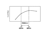
- FIG. 8 is a graph showing a change in torque of the rotor 9 when the vertical axis is the torque [N ⁇ m] of the rotor 9 and the horizontal axis is the salient pole width [mm] of the salient pole 35 provided on the rotor core 32. It is. More specifically, FIG. 8 is a graph showing the torque generated in the rotor 9 of the present embodiment when the circumferential width dimension (electrical angle ⁇ ) of the salient pole 35 is varied.
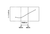
- FIG. 9 is a graph showing changes in the ripple rate of the rotor 9 when the vertical axis is the ripple rate [%] of the rotor 9 and the horizontal axis is the salient pole width [mm] of the salient pole 35 of the rotor core 32.
- FIG. 9 is a graph showing a ripple rate generated in the rotor 9 of the present embodiment when the circumferential width dimension of the salient pole 35 is varied.
- FIG. 10 is a graph showing changes in cogging of the rotor 9 when the vertical axis is the cogging [mN ⁇ m] of the rotor 9 and the horizontal axis is the salient pole width [mm] of the salient pole 35 of the rotor core 32. More specifically, FIG. 10 is a graph showing cogging generated in the rotor 9 of the present embodiment when the circumferential width of the salient pole 35 is varied.
- a high reluctance torque can be obtained. It can also be confirmed that the ripple rate and cogging torque of the motor unit 2 can be suppressed.
- the inductance value in the q-axis direction can be reduced by setting the electrical angle ⁇ 1 of the salient pole 35 to 40 ° or less and reducing the circumferential width dimension of the salient pole 35 in the circumferential direction.
- Demagnetizing field can be suppressed.
- the electrical angle ⁇ 1 of the salient pole 35 to 20 ° or more and ensuring the circumferential width dimension to be a certain level or more, the magnetic flux concentrates on the salient pole 35, so that the demagnetizing field becomes the end 33s of the permanent magnet 33. The effect that it becomes difficult to act on can be obtained reliably.
- a high reluctance torque can be obtained by setting the electrical angle ⁇ 1 of the salient pole 35 to 20 ° or more and 40 ° or less.
- the inclined surfaces 33 e on both sides in the circumferential direction are parallel to a straight line L ⁇ b> 1 connecting the circumferential intermediate portion 33 c of the permanent magnet 33 and the axis C ⁇ b> 1 of the shaft 31.
- the two inclined surfaces 33e are also parallel to each other.
- the permanent magnet 33 can be formed from a material having two parallel inclined surfaces 33e facing each other, and the manufacturing cost of the permanent magnet 33 can be reduced.
- the salient pole 35 is formed so that both side surfaces 35c facing each other in the circumferential direction are parallel to each other. That is, the salient pole 35 is formed so that the circumferential width dimension is uniform in the radial direction. For this reason, for example, the saturation of the magnetic flux flowing through the salient poles 35 can be suppressed as compared with the case where the salient poles 35 are trapezoidal when viewed from the rotation axis direction.
- the wiper motor 1 is taken as an example of the motor.
- the motor according to the present invention is not limited to the wiper motor 1, and other electrical components (for example, a power window, a sunroof, It can be used as a driving source for an electric seat or the like, and for various other purposes.
- one groove portion 91 is formed in the axially outer end portion 35t of the salient pole 35 at substantially the center in the circumferential direction.
- the present invention is not limited to this, and two or more groove portions 91 may be formed in the end portion 35 t of the salient pole 35.
- the groove part 91 demonstrated the case where it formed in the substantially V-groove shape so that the groove width of the circumferential direction may become narrow gradually as it goes to radial inside.
- the present invention is not limited to this, and it is only necessary that the groove portion 91 is formed so that the groove width in the circumferential direction gradually decreases toward the inner side in the radial direction.
- the groove portion 91 is formed in a substantially U shape. May be.
- the inclined surface 33e formed on the permanent magnet 33 is inclined so as to be gradually separated from the salient pole 35 as it goes from the radially outer end of the salient pole contact surface 33d toward the outer peripheral surface 33a of the permanent magnet 33, and The case where it is formed flat has been described.
- the inclined surface 33e only needs to be formed so as to be gradually separated from the salient poles 35 toward the outer peripheral surface 33a of the permanent magnet 33 from the radially outer end of the salient pole contact surface 33d.
- the inclined surface 33e may be formed in a curved shape.
- SYMBOLS 1 Wiper motor (motor, brushless wiper motor), 2 ... Motor part (motor), 8 ... Stator, 20 ... Stator core, 22 ... Teeth, 24 ... Coil, 31 ... Shaft, 32 ... Rotor core, 33 ... Permanent magnet, 33e ... inclined surface (slope), 33f ... outer peripheral corner (corner), 35 ... salient pole, 91 ... groove, 91a ... bottom, C1 ... axis (rotation axis), H1 ... groove depth, L1, L2, L3 ... Linear, ⁇ 1, ⁇ 2 ... Electrical angle
Landscapes
- Engineering & Computer Science (AREA)
- Power Engineering (AREA)
- Mechanical Engineering (AREA)
- Permanent Field Magnets Of Synchronous Machinery (AREA)
- Iron Core Of Rotating Electric Machines (AREA)
- Permanent Magnet Type Synchronous Machine (AREA)
Abstract
L'invention concerne un moteur et un moteur d'essuie-glace sans balai capables d'empêcher un noyau de rotor de s'arrêter à un angle de rotation où des aimants permanents sont le plus facilement démagnétisés lorsque le rapport du nombre de pôles magnétiques des aimants permanents au nombre de dents est de 2:3. Le moteur est pourvu : d'un noyau de rotor (32) ; d'une pluralité d'aimants permanents (33) situés sur la surface circonférentielle extérieure (32b) du noyau de rotor (32) et magnétisés dans une orientation parallèle ; et un pôle saillant (35) formé de manière saillante entre les aimants permanents (33) adjacents dans la direction circonférentielle de la surface circonférentielle externe (32b) du noyau de rotor (32). Le rapport du nombre de pôles magnétiques des aimants permanents (33) au nombre de dents est de 2:3. Des surfaces inclinées (33e) sont formées sur les surfaces latérales des aimants permanents (33) dans la direction circonférentielle. L'angle θ2 entre les lignes L3 et les lignes L2 est un angle électrique de 13° ou plus, lesdites lignes L3 reliant des parties de coin circonférentielles externes (33f), où les surfaces inclinées (33e) et la surface circonférentielle externe (33a) sont reliées l'une à l'autre, et le centre de l'arbre C1, lesdites lignes L2 reliant le côté le plus à l'extérieur de la direction radiale de la surface latérale de la direction circonférentielle du pôle saillant (35) et du centre de l'arbre C1.
Priority Applications (3)
| Application Number | Priority Date | Filing Date | Title |
|---|---|---|---|
| CN201980022175.3A CN111919359B (zh) | 2018-04-12 | 2019-03-22 | 马达以及无刷雨刮器马达 |
| US17/041,429 US11496031B2 (en) | 2018-04-12 | 2019-03-22 | Motor and brushless wiper motor |
| EP19785388.0A EP3780348B1 (fr) | 2018-04-12 | 2019-03-22 | Moteur et moteur d'essuie-glace sans balai |
Applications Claiming Priority (2)
| Application Number | Priority Date | Filing Date | Title |
|---|---|---|---|
| JP2018-076679 | 2018-04-12 | ||
| JP2018076679A JP7080703B2 (ja) | 2018-04-12 | 2018-04-12 | モータ及びブラシレスワイパーモータ |
Publications (1)
| Publication Number | Publication Date |
|---|---|
| WO2019198464A1 true WO2019198464A1 (fr) | 2019-10-17 |
Family
ID=68164258
Family Applications (1)
| Application Number | Title | Priority Date | Filing Date |
|---|---|---|---|
| PCT/JP2019/012074 Ceased WO2019198464A1 (fr) | 2018-04-12 | 2019-03-22 | Moteur et moteur d'essuie-glace sans balai |
Country Status (5)
| Country | Link |
|---|---|
| US (1) | US11496031B2 (fr) |
| EP (1) | EP3780348B1 (fr) |
| JP (1) | JP7080703B2 (fr) |
| CN (1) | CN111919359B (fr) |
| WO (1) | WO2019198464A1 (fr) |
Families Citing this family (3)
| Publication number | Priority date | Publication date | Assignee | Title |
|---|---|---|---|---|
| JP7080702B2 (ja) * | 2018-04-12 | 2022-06-06 | 株式会社ミツバ | モータ及びブラシレスワイパーモータ |
| JP7349313B2 (ja) | 2019-10-10 | 2023-09-22 | 西川ゴム工業株式会社 | センサー付きプロテクター |
| JP2022134965A (ja) * | 2021-03-04 | 2022-09-15 | 株式会社ミツバ | モータ及び減速機付きモータ |
Citations (8)
| Publication number | Priority date | Publication date | Assignee | Title |
|---|---|---|---|---|
| JP2002262533A (ja) | 2001-02-28 | 2002-09-13 | Hitachi Ltd | 永久磁石式回転電機 |
| JP2004048970A (ja) * | 2002-07-16 | 2004-02-12 | Meidensha Corp | 永久磁石形回転電機 |
| JP2005065417A (ja) * | 2003-08-13 | 2005-03-10 | Aichi Electric Co Ltd | 永久磁石式同期電動機 |
| JP2006081383A (ja) * | 2004-09-09 | 2006-03-23 | Samsung Kwangju Electronics Co Ltd | 面取りされたマグネット付きブラシレス直流モーター |
| JP2008245406A (ja) * | 2007-03-27 | 2008-10-09 | Yaskawa Electric Corp | 表面型永久磁石同期機用ロータとそれを用いた同期機 |
| WO2014167645A1 (fr) * | 2013-04-09 | 2014-10-16 | 三菱電機株式会社 | Moteur de type à aimant permanent et appareil de servodirection électrique |
| JP2016175638A (ja) * | 2015-03-19 | 2016-10-06 | 株式会社ミツバ | ブラシレスモータおよびワイパ装置 |
| WO2017002873A1 (fr) * | 2015-06-29 | 2017-01-05 | 株式会社ミツバ | Moteur sans balai |
Family Cites Families (13)
| Publication number | Priority date | Publication date | Assignee | Title |
|---|---|---|---|---|
| JPH1127878A (ja) | 1997-06-30 | 1999-01-29 | Mitsubishi Heavy Ind Ltd | モータ |
| JP4791013B2 (ja) | 2004-07-22 | 2011-10-12 | 三菱電機株式会社 | ブラシレスモータ |
| DE102012011445A1 (de) * | 2011-06-21 | 2012-12-27 | Asmo, Ltd. | Motor mit einem Rotor und Verfahren zur Herstellung des Rotors |
| JP5594304B2 (ja) * | 2012-02-13 | 2014-09-24 | 株式会社安川電機 | 回転電機 |
| JP5605721B2 (ja) * | 2012-06-29 | 2014-10-15 | 株式会社デンソー | 回転電機 |
| JP2015027161A (ja) | 2013-07-25 | 2015-02-05 | 株式会社東芝 | 回転電機 |
| CN105556812A (zh) * | 2013-09-24 | 2016-05-04 | 株式会社美姿把 | 无刷雨刮器电机 |
| US9515528B2 (en) | 2014-01-06 | 2016-12-06 | Mitsubishi Electric Corporation | Permanent magnet rotary electric machine |
| US9705366B2 (en) * | 2014-04-08 | 2017-07-11 | Mitsubishi Electric Corporation | Embedded permanent magnet rotary electric machine |
| JP2015231254A (ja) * | 2014-06-03 | 2015-12-21 | アスモ株式会社 | 回転子及びこれを備えた回転電機 |
| DE102015119020A1 (de) * | 2015-11-05 | 2017-05-11 | Minebea Co., Ltd. | Elektrische Maschine |
| CN107425685B (zh) | 2017-06-30 | 2023-07-14 | 珠海格力节能环保制冷技术研究中心有限公司 | 电机及压缩机 |
| CN107276272B (zh) | 2017-08-09 | 2023-09-26 | 珠海格力节能环保制冷技术研究中心有限公司 | 表贴式电机、表贴式电机转子及定子 |
-
2018
- 2018-04-12 JP JP2018076679A patent/JP7080703B2/ja active Active
-
2019
- 2019-03-22 WO PCT/JP2019/012074 patent/WO2019198464A1/fr not_active Ceased
- 2019-03-22 CN CN201980022175.3A patent/CN111919359B/zh active Active
- 2019-03-22 EP EP19785388.0A patent/EP3780348B1/fr active Active
- 2019-03-22 US US17/041,429 patent/US11496031B2/en active Active
Patent Citations (8)
| Publication number | Priority date | Publication date | Assignee | Title |
|---|---|---|---|---|
| JP2002262533A (ja) | 2001-02-28 | 2002-09-13 | Hitachi Ltd | 永久磁石式回転電機 |
| JP2004048970A (ja) * | 2002-07-16 | 2004-02-12 | Meidensha Corp | 永久磁石形回転電機 |
| JP2005065417A (ja) * | 2003-08-13 | 2005-03-10 | Aichi Electric Co Ltd | 永久磁石式同期電動機 |
| JP2006081383A (ja) * | 2004-09-09 | 2006-03-23 | Samsung Kwangju Electronics Co Ltd | 面取りされたマグネット付きブラシレス直流モーター |
| JP2008245406A (ja) * | 2007-03-27 | 2008-10-09 | Yaskawa Electric Corp | 表面型永久磁石同期機用ロータとそれを用いた同期機 |
| WO2014167645A1 (fr) * | 2013-04-09 | 2014-10-16 | 三菱電機株式会社 | Moteur de type à aimant permanent et appareil de servodirection électrique |
| JP2016175638A (ja) * | 2015-03-19 | 2016-10-06 | 株式会社ミツバ | ブラシレスモータおよびワイパ装置 |
| WO2017002873A1 (fr) * | 2015-06-29 | 2017-01-05 | 株式会社ミツバ | Moteur sans balai |
Also Published As
| Publication number | Publication date |
|---|---|
| US20210021183A1 (en) | 2021-01-21 |
| EP3780348B1 (fr) | 2023-12-20 |
| CN111919359B (zh) | 2023-04-04 |
| EP3780348A1 (fr) | 2021-02-17 |
| JP7080703B2 (ja) | 2022-06-06 |
| JP2019187133A (ja) | 2019-10-24 |
| CN111919359A (zh) | 2020-11-10 |
| US11496031B2 (en) | 2022-11-08 |
| EP3780348A4 (fr) | 2021-12-29 |
Similar Documents
| Publication | Publication Date | Title |
|---|---|---|
| US11289960B2 (en) | Motor and brushless wiper motor | |
| US12191714B2 (en) | Rotor, motor and brushless motor | |
| US11901779B2 (en) | Motor and brushless wiper motor | |
| JP6870989B2 (ja) | ロータおよび電動モータ | |
| WO2019198464A1 (fr) | Moteur et moteur d'essuie-glace sans balai | |
| JP7105624B2 (ja) | モータ及びブラシレスワイパーモータ | |
| WO2019202915A1 (fr) | Moteur, moteur d'essuie-glace sans balai et procédé de commande de moteur | |
| JP7077153B2 (ja) | モータ及びブラシレスワイパーモータ | |
| JP6655500B2 (ja) | 電動モータ | |
| JP2020078177A (ja) | ロータ、モータ及びブラシレスワイパーモータ | |
| JP2020078176A (ja) | ロータ、モータ及びブラシレスワイパーモータ | |
| EP3657637B1 (fr) | Moteur et moteur d'essuie-glace sans balais | |
| JP2020178387A (ja) | モータ、及びワイパモータ | |
| WO2020100457A1 (fr) | Moteur et moteur d'essuie-glace sans balai | |
| JP7122944B2 (ja) | ロータ、モータ及びブラシレスワイパーモータ | |
| JP2020115733A (ja) | モータ及びブラシレスワイパーモータ | |
| JP2023161321A (ja) | 電動モータ | |
| JP2024071969A (ja) | 回転電機 |
Legal Events
| Date | Code | Title | Description |
|---|---|---|---|
| 121 | Ep: the epo has been informed by wipo that ep was designated in this application |
Ref document number: 19785388 Country of ref document: EP Kind code of ref document: A1 |
|
| NENP | Non-entry into the national phase |
Ref country code: DE |
|
| WWE | Wipo information: entry into national phase |
Ref document number: 2019785388 Country of ref document: EP |
|
| ENP | Entry into the national phase |
Ref document number: 2019785388 Country of ref document: EP Effective date: 20201112 |