WO2019198569A1 - 磁性配線回路基板 - Google Patents
磁性配線回路基板 Download PDFInfo
- Publication number
- WO2019198569A1 WO2019198569A1 PCT/JP2019/014644 JP2019014644W WO2019198569A1 WO 2019198569 A1 WO2019198569 A1 WO 2019198569A1 JP 2019014644 W JP2019014644 W JP 2019014644W WO 2019198569 A1 WO2019198569 A1 WO 2019198569A1
- Authority
- WO
- WIPO (PCT)
- Prior art keywords
- wiring
- magnetic
- thickness direction
- circuit board
- insulating layer
- Prior art date
- Legal status (The legal status is an assumption and is not a legal conclusion. Google has not performed a legal analysis and makes no representation as to the accuracy of the status listed.)
- Ceased
Links
Images


Classifications
-
- H—ELECTRICITY
- H05—ELECTRIC TECHNIQUES NOT OTHERWISE PROVIDED FOR
- H05K—PRINTED CIRCUITS; CASINGS OR CONSTRUCTIONAL DETAILS OF ELECTRIC APPARATUS; MANUFACTURE OF ASSEMBLAGES OF ELECTRICAL COMPONENTS
- H05K1/00—Printed circuits
- H05K1/16—Printed circuits incorporating printed electric components, e.g. printed resistors, capacitors or inductors
- H05K1/165—Printed circuits incorporating printed electric components, e.g. printed resistors, capacitors or inductors incorporating printed inductors
-
- H—ELECTRICITY
- H01—ELECTRIC ELEMENTS
- H01F—MAGNETS; INDUCTANCES; TRANSFORMERS; SELECTION OF MATERIALS FOR THEIR MAGNETIC PROPERTIES
- H01F17/00—Fixed inductances of the signal type
- H01F17/04—Fixed inductances of the signal type with magnetic core
-
- H—ELECTRICITY
- H05—ELECTRIC TECHNIQUES NOT OTHERWISE PROVIDED FOR
- H05K—PRINTED CIRCUITS; CASINGS OR CONSTRUCTIONAL DETAILS OF ELECTRIC APPARATUS; MANUFACTURE OF ASSEMBLAGES OF ELECTRICAL COMPONENTS
- H05K1/00—Printed circuits
- H05K1/02—Details
- H05K1/0213—Electrical arrangements not otherwise provided for
- H05K1/0216—Reduction of cross-talk, noise or electromagnetic interference
- H05K1/0218—Reduction of cross-talk, noise or electromagnetic interference by printed shielding conductors, ground planes or power plane
- H05K1/0224—Patterned shielding planes, ground planes or power planes
-
- B—PERFORMING OPERATIONS; TRANSPORTING
- B32—LAYERED PRODUCTS
- B32B—LAYERED PRODUCTS, i.e. PRODUCTS BUILT-UP OF STRATA OF FLAT OR NON-FLAT, e.g. CELLULAR OR HONEYCOMB, FORM
- B32B15/00—Layered products comprising a layer of metal
- B32B15/04—Layered products comprising a layer of metal comprising metal as the main or only constituent of a layer, which is next to another layer of the same or of a different material
- B32B15/08—Layered products comprising a layer of metal comprising metal as the main or only constituent of a layer, which is next to another layer of the same or of a different material of synthetic resin
-
- H—ELECTRICITY
- H01—ELECTRIC ELEMENTS
- H01F—MAGNETS; INDUCTANCES; TRANSFORMERS; SELECTION OF MATERIALS FOR THEIR MAGNETIC PROPERTIES
- H01F27/00—Details of transformers or inductances, in general
- H01F27/34—Special means for preventing or reducing unwanted electric or magnetic effects, e.g. no-load losses, reactive currents, harmonics, oscillations, leakage fields
- H01F27/36—Electric or magnetic shields or screens
- H01F27/366—Electric or magnetic shields or screens made of ferromagnetic material
-
- H—ELECTRICITY
- H01—ELECTRIC ELEMENTS
- H01F—MAGNETS; INDUCTANCES; TRANSFORMERS; SELECTION OF MATERIALS FOR THEIR MAGNETIC PROPERTIES
- H01F41/00—Apparatus or processes specially adapted for manufacturing or assembling magnets, inductances or transformers; Apparatus or processes specially adapted for manufacturing materials characterised by their magnetic properties
- H01F41/02—Apparatus or processes specially adapted for manufacturing or assembling magnets, inductances or transformers; Apparatus or processes specially adapted for manufacturing materials characterised by their magnetic properties for manufacturing cores, coils, or magnets
- H01F41/04—Apparatus or processes specially adapted for manufacturing or assembling magnets, inductances or transformers; Apparatus or processes specially adapted for manufacturing materials characterised by their magnetic properties for manufacturing cores, coils, or magnets for manufacturing coils
- H01F41/041—Printed circuit coils
- H01F41/046—Printed circuit coils structurally combined with ferromagnetic material
-
- H—ELECTRICITY
- H01—ELECTRIC ELEMENTS
- H01F—MAGNETS; INDUCTANCES; TRANSFORMERS; SELECTION OF MATERIALS FOR THEIR MAGNETIC PROPERTIES
- H01F5/00—Coils
- H01F5/003—Printed circuit coils
-
- H—ELECTRICITY
- H05—ELECTRIC TECHNIQUES NOT OTHERWISE PROVIDED FOR
- H05K—PRINTED CIRCUITS; CASINGS OR CONSTRUCTIONAL DETAILS OF ELECTRIC APPARATUS; MANUFACTURE OF ASSEMBLAGES OF ELECTRICAL COMPONENTS
- H05K1/00—Printed circuits
- H05K1/02—Details
- H05K1/03—Use of materials for the substrate
-
- H—ELECTRICITY
- H05—ELECTRIC TECHNIQUES NOT OTHERWISE PROVIDED FOR
- H05K—PRINTED CIRCUITS; CASINGS OR CONSTRUCTIONAL DETAILS OF ELECTRIC APPARATUS; MANUFACTURE OF ASSEMBLAGES OF ELECTRICAL COMPONENTS
- H05K1/00—Printed circuits
- H05K1/16—Printed circuits incorporating printed electric components, e.g. printed resistors, capacitors or inductors
-
- H—ELECTRICITY
- H05—ELECTRIC TECHNIQUES NOT OTHERWISE PROVIDED FOR
- H05K—PRINTED CIRCUITS; CASINGS OR CONSTRUCTIONAL DETAILS OF ELECTRIC APPARATUS; MANUFACTURE OF ASSEMBLAGES OF ELECTRICAL COMPONENTS
- H05K9/00—Screening of apparatus or components against electric or magnetic fields
-
- H—ELECTRICITY
- H01—ELECTRIC ELEMENTS
- H01F—MAGNETS; INDUCTANCES; TRANSFORMERS; SELECTION OF MATERIALS FOR THEIR MAGNETIC PROPERTIES
- H01F17/00—Fixed inductances of the signal type
- H01F17/04—Fixed inductances of the signal type with magnetic core
- H01F2017/048—Fixed inductances of the signal type with magnetic core with encapsulating core, e.g. made of resin and magnetic powder
-
- H—ELECTRICITY
- H05—ELECTRIC TECHNIQUES NOT OTHERWISE PROVIDED FOR
- H05K—PRINTED CIRCUITS; CASINGS OR CONSTRUCTIONAL DETAILS OF ELECTRIC APPARATUS; MANUFACTURE OF ASSEMBLAGES OF ELECTRICAL COMPONENTS
- H05K1/00—Printed circuits
- H05K1/02—Details
- H05K1/0213—Electrical arrangements not otherwise provided for
- H05K1/0237—High frequency adaptations
- H05K1/024—Dielectric details, e.g. changing the dielectric material around a transmission line
-
- H—ELECTRICITY
- H05—ELECTRIC TECHNIQUES NOT OTHERWISE PROVIDED FOR
- H05K—PRINTED CIRCUITS; CASINGS OR CONSTRUCTIONAL DETAILS OF ELECTRIC APPARATUS; MANUFACTURE OF ASSEMBLAGES OF ELECTRICAL COMPONENTS
- H05K2201/00—Indexing scheme relating to printed circuits covered by H05K1/00
- H05K2201/08—Magnetic details
- H05K2201/083—Magnetic materials
- H05K2201/086—Magnetic materials for inductive purposes, e.g. printed inductor with ferrite core
-
- H—ELECTRICITY
- H05—ELECTRIC TECHNIQUES NOT OTHERWISE PROVIDED FOR
- H05K—PRINTED CIRCUITS; CASINGS OR CONSTRUCTIONAL DETAILS OF ELECTRIC APPARATUS; MANUFACTURE OF ASSEMBLAGES OF ELECTRICAL COMPONENTS
- H05K2203/00—Indexing scheme relating to apparatus or processes for manufacturing printed circuits covered by H05K3/00
- H05K2203/02—Details related to mechanical or acoustic processing, e.g. drilling, punching, cutting, using ultrasound
- H05K2203/0228—Cutting, sawing, milling or shearing
-
- H—ELECTRICITY
- H05—ELECTRIC TECHNIQUES NOT OTHERWISE PROVIDED FOR
- H05K—PRINTED CIRCUITS; CASINGS OR CONSTRUCTIONAL DETAILS OF ELECTRIC APPARATUS; MANUFACTURE OF ASSEMBLAGES OF ELECTRICAL COMPONENTS
- H05K3/00—Apparatus or processes for manufacturing printed circuits
- H05K3/22—Secondary treatment of printed circuits
- H05K3/28—Applying non-metallic protective coatings
- H05K3/281—Applying non-metallic protective coatings by means of a preformed insulating foil
Definitions
- the present invention relates to a magnetic wiring circuit board.
- Patent Document 1 a magnetic wiring circuit board including a plurality of wirings and a magnetic layer in which the wirings are embedded is known (see, for example, Patent Document 1).
- the present invention provides a magnetic wiring circuit board capable of suppressing generation of noise in adjacent wiring portions.
- the present invention (1) includes an insulating layer, a plurality of wiring portions arranged on the one surface in the thickness direction of the insulating layer at intervals in an orthogonal direction orthogonal to the thickness direction, and the thickness direction of the insulating layer
- a magnetic layer disposed so as to embed the plurality of wiring portions on one side, wherein one side in the thickness direction of the magnetic layer is one side in the thickness direction with respect to one side in the thickness direction of the plurality of wiring units And at least two of the wiring portions adjacent to each other, and from the one surface in the thickness direction of the magnetic layer, the thickness direction of the at least two wiring portions.
- a magnetic wiring circuit board is provided that includes a suppression portion that is formed so as to extend toward the other side in the thickness direction from a virtual line that connects the one surface and suppresses magnetic coupling between the at least two wiring portions.
- the magnetic layer extends from the one side in the thickness direction of the magnetic layer toward the other side in the thickness direction from the virtual line connecting the one side in the thickness direction of the at least two wiring portions. Magnetic coupling between adjacent wiring portions can be suppressed. Therefore, it is possible to suppress the generation of noise in adjacent wiring portions.
- the present invention (2) includes the magnetic wiring circuit board according to (1), wherein the suppressing portion reaches one surface in the thickness direction of the insulating layer.
- the suppressing portion since the suppressing portion reaches one surface in the thickness direction of the insulating layer, the magnetic coupling of the wiring portion is more reliably suppressed, and the generation of noise in the wiring portion is more reliably suppressed. can do.
- the present invention (3) includes the magnetic wiring circuit board according to (1) or (2), wherein the suppressing portion is a slit formed in the magnetic layer.
- the suppressing portion is a slit, the configuration is simple.
- the ratio (W / S) of the orthogonal direction length W in the suppressing part to the orthogonal direction length S between the at least two wiring parts is 0.4 or less.
- the magnetic wiring circuit board according to any one of (3) is included.
- the ratio of the orthogonal length W in the restraining portion to the orthogonal length S between the plurality of wiring portions is as low as 0.4 or less, so the relative permeability between the wiring portions is low. An excessive decrease can be suppressed and a high inductance can be secured.
- the magnetic coupling between the adjacent wiring portions can be suppressed by the suppressing portion, and the generation of noise in the adjacent wiring portions can be suppressed.
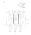
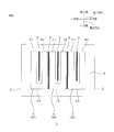
- FIG. 1 shows a plan view of an embodiment of a magnetic wired circuit board according to the present invention.
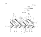
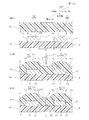
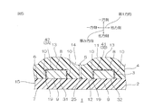
- FIG. 2 is a sectional view taken along line XX of the magnetic wiring circuit board shown in FIG. 3A to 3C are manufacturing process diagrams of the magnetic wiring circuit board shown in FIG. 2.
- FIG. 3A is a process of preparing the wiring circuit board and the magnetic sheet
- FIG. 3B is a hot press of the magnetic sheet to the wiring circuit board.
- FIG. 3C shows a step of forming the suppressing portion.
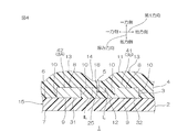
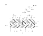
- FIG. 4 is a modification of the magnetic wiring circuit board shown in FIG. 2, and shows a mode in which the suppressing portion extends partway in the thickness direction of the magnetic layer.
- FIG. 5 shows a modification of the magnetic wiring circuit board shown in FIG.
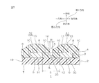
- FIG. 6 is a modified example of the magnetic wired circuit board shown in FIG. 2, and shows a mode in which the suppressing portion includes a filling portion.
- FIG. 7 is a modified example of the magnetic wiring circuit board shown in FIG. 2 and shows a mode in which the suppressing portion (slit) has a tapered shape.
- FIG. 8 shows a modification of the magnetic wiring circuit board shown in FIG.
- FIG. 9 shows a modification of the magnetic wiring circuit board shown in FIG.
- FIG. 10 is a plan view showing the magnetic wiring circuit board of the example.
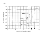
- FIG. 11 shows a graph of evaluation 1 in the example.
- FIG. 12 shows a graph of evaluation 2 in the example.
- a wired circuit board 1 as an embodiment of the wired circuit board of the present invention will be described with reference to FIGS. 1 and 2.
- the magnetic wired circuit board 1 has one surface in the thickness direction and the other surface facing each other in the thickness direction, and in a surface direction (a direction orthogonal to the thickness direction) (a surface direction including a first direction and a second direction described later). It has a sheet shape that extends.
- the magnetic wiring circuit board 1 includes an insulating layer 2, a plurality of wirings 3, a magnetic layer 4, and a suppressing unit 5.
- the insulating layer 2 has a sheet shape extending in the surface direction.
- the insulating layer 2 has a first insulating surface 6 that is one surface in the thickness direction and a second insulating surface 7 that is the other surface.
- the insulating layer 2 is a support material that supports a plurality of wirings 3 to be described below, and by extension, is also a support layer that supports the magnetic wiring circuit board 1.
- the insulating layer 2 has flexibility. Examples of the material for the insulating layer 2 include resin materials such as polyimide resin, polyester resin, and acrylic resin.
- the insulating layer 2 may be either a single layer or a multilayer.
- the thickness of the insulating layer 2 is not specifically limited, For example, they are 1 micrometer or more and 1000 micrometers or less.
- a plurality of wirings 3 are arranged on the first insulating surface 6 of the insulating layer 2 in the first direction (corresponding to the left-right direction in FIG. 2 and included in the surface direction) with a space therebetween.
- the wiring 3 includes a first wiring 3A, a second wiring 3B, and a third wiring 3C arranged in parallel at intervals in the first direction.
- the first wiring 3A, the second wiring 3B, and the third wiring 3C are arranged in order from one side in the first direction toward the second direction.
- each of the plurality of wirings 3 is, for example, a substantially U shape.
- Each of the plurality of wirings 3 includes a first wiring portion 41 and a second wiring portion as an example of a plurality of wiring portions extending in a thickness direction and a second direction orthogonal to the first direction (a direction corresponding to a depth direction in FIG. 2).
- the wiring part 42 and the connection wiring part 43 which connects the 1st wiring part 41 and the 2nd direction one end part of the 2nd wiring part 42 are integrally provided.
- the first wiring part 41 and the second wiring part 42 are arranged to face each other with a gap in the first direction (an example of a predetermined direction).
- the first wiring portion 41 and the second wiring portion 42 are spaced apart from each other in a cross-sectional view orthogonal to the second direction (cut surface along the first direction and thickness direction) (cut surface shown in FIG. 2). Next to each other.
- the first wiring part 41 and the second wiring part 42 are provided with a plurality of wirings 3 in the magnetic wiring circuit board 1, respectively.
- each of the first wiring portion 41 and the second wiring portion 42 is not particularly limited. Etc.
- Each of the first wiring portion 41 and the second wiring portion 42 is a first wiring surface that is one surface in the thickness direction and is opposed to the first insulating surface 6 of the insulating layer 2 with a space on one side in the thickness direction.
- a second wiring surface 9 that contacts the first insulating surface 6 of the insulating layer 2
- a third wiring surface 10 that is a side surface that connects both the first wiring surface 8 and both end edges in the first direction of the second wiring surface 9. And are integrated.
- the first wiring surface 8 is a flat surface along the first direction.
- the second wiring surface 9 is a flat surface parallel to the first wiring surface 8.
- the third wiring surface 10 extends along the thickness direction. Two third wiring surfaces 10 are provided in each of the first wiring portion 41 and the second wiring portion 42. The two third wiring surfaces 10 are arranged to face each other with an interval in the first direction.
- connection wiring part 43 has the same sectional view shape as each of the first wiring part 41 and the second wiring part 42.
- the material of the wiring 3 includes, for example, a metal (conductor) such as copper.
- the thickness of the wiring 3 is, for example, 10 ⁇ m or more, preferably 30 ⁇ m or more, and, for example, 500 ⁇ m or less, preferably 250 ⁇ m or less.
- the widths of the first wiring part 41 and the second wiring part 42 are, for example, 20 ⁇ m or more and 2000 ⁇ m or less.
- the distance between the first wiring part 41 and the second wiring part 42 is, for example, 20 ⁇ m or more, preferably 50 ⁇ m or more, and for example, 2000 ⁇ m or less, preferably 1500 ⁇ m or less.
- the ratio (thickness / width) of the thickness of the wiring 3 (the first wiring portion 41 and the second wiring portion 42) to the width of the first wiring portion 41 and the second wiring portion 42 is, for example, 0.005 or more, preferably 0.015 or more, and for example, 25 or less, preferably 12.5 or less.
- the ratio (thickness / interval) of the thickness of the wiring 3 to the distance between the first wiring part 41 and the second wiring part 42 is, for example, 0.005 or more, preferably 0.02 or more. 25 or less, preferably 5 or less.
- the wiring 3 is provided on the printed circuit board 15 together with the insulating layer 2 described above. That is, the printed circuit board 15 includes the insulating layer 2 and the plurality of wirings 3. Preferably, the printed circuit board 15 includes only the insulating layer 2 and the plurality of wirings 3.
- the magnetic layer 4 has a sheet shape extending in the surface direction.
- the magnetic layer 4 is arranged so that a plurality of wirings 3 are embedded in the first insulating surface 6 of the insulating layer 2.
- the magnetic layer 4 includes a first magnetic surface 11 and a second magnetic surface 12 that is disposed on the other side in the thickness direction of the first magnetic surface 11 with a space therebetween.
- the first magnetic surface 11 is disposed at a distance on one side in the thickness direction with respect to the first wiring surface 8 of at least the first wiring portion 41 and the second wiring portion 42.
- the first magnetic surface 11 includes a plurality of protrusions 13 protruding toward one side in the thickness direction corresponding to the first wiring part 41 and the second wiring part 42, and the protrusions 13 adjacent to each other.
- a concave portion 14 which is disposed between the convex portion 13 and sinks toward the other side in the thickness direction.
- the concave portion 14 (more specifically, the other edge in the thickness direction of the concave portion 14) is one side in the thickness direction from the virtual line IL connecting the first wiring surface 8 of the first wiring portion 41 and the second wiring portion 42. Are located at intervals.
- the second magnetic surface 12 covers the first insulating surface 6 exposed from the wiring 3 in the insulating layer 2 and the first wiring surface 8 and the third wiring surface 10 of the wiring 3.
- Examples of the material of the magnetic layer 4 include a magnetic composition containing magnetic particles and a resin component.
- Examples of the magnetic particles include soft magnetic particles such as Sendust from the viewpoint of magnetic properties.
- Examples of the resin component include thermosetting resins such as an epoxy resin composition containing an epoxy resin, a curing agent, and a curing accelerator. Such magnetic compositions are described in, for example, JP-A-2017-005115, JP-A-2015-092543.
- the content ratio of the magnetic particles in the magnetic layer 4 is, for example, 50% by volume or more, preferably 55% by volume or more, and for example, 95% by volume or less, preferably 90% by volume or less.
- the relative magnetic permeability of the magnetic layer 4 is, for example, 3 or more, preferably 5 or more, more preferably 10 or more, and for example 1000 or less.
- the suppression unit 5 suppresses magnetic coupling between two wiring units adjacent to each other.
- the suppressing unit 5 includes the second wiring part 42 of the one wiring 3 and the second wiring 3 of the other wiring 3 adjacent to the one wiring 3.
- the thickness is larger than the virtual line IL connecting the first wiring surface 41 of the magnetic layer 4 and the first wiring surface 8 of the first wiring portion 41 and the second wiring portion 42. It is formed to extend in the other direction.
- the suppressing unit 5 includes the second wiring part 42 of the first wiring 3A and the first wiring part 41 of the second wiring 3B, and the second wiring part of the second wiring 3B. 42 and the first wiring portion 41 of the third wiring 3C.
- the suppressing portion 5 extends from the first magnetic surface 11 of the magnetic layer 4 to the first insulating surface 6 of the insulating layer 2.
- the suppressing portion 5 is a slit (gap, gap, opening) 25 formed in the magnetic layer 4.
- the suppression part 5 consists only of the slit 25 (The filling part 20 is not provided like the modification shown in FIG. 6 mentioned later).
- the suppressing portion 5 has a substantially linear cross section extending from the concave portion 14 of the magnetic layer 4 along the thickness direction. That is, the suppressing part 5 has a shape in which the width (first direction length) W is the same in the thickness direction. Further, the suppressing unit 5 divides (separates) the magnetic layer 4 in the first direction when viewed in cross section (thickness direction and cross section along the first direction).
- the suppressing portion 5 is formed between the two wiring portions adjacent to each other along the second direction.
- the suppression unit 5 has, for example, a substantially straight shape in plan view along the second wiring unit 42 of one wiring 3 and the first wiring unit 41 of the other wiring 3.
- the ratio (W / S) of the width (first direction length) W of the suppressing portion 5 to the spacing S between the first wiring portion 41 and the second wiring portion 42 adjacent to each other is, for example, 0.7 or less, preferably Is 0.5 or less, more preferably 0.4 or less, even more preferably 0.3 or less, particularly preferably 0.2 or less, and most preferably 0.1 or less. .01 or more. If the above ratio (W / S) is equal to or less than the above upper limit, an excessive decrease in the relative permeability between the wirings 3 can be suppressed, and a high inductance in the magnetic wiring circuit board 1 can be ensured.
- the first direction length (width) W of the suppressing portion 5 is, for example, 100 ⁇ m or less, preferably 80 ⁇ m or less, more preferably 60 ⁇ m or less, and for example, 1 ⁇ m or more.
- the thickness direction length of the suppression part 5 is the same as the thickness of the magnetic layer 4 in the recessed part 14.
- the relative magnetic permeability in the suppression unit 5 is substantially 1 (specifically, a value approximated to the relative magnetic permeability 1 in vacuum) when the suppression unit 5 is the slit 25 and air exists in the suppression unit 5. is there.
- the thickness of the magnetic wiring circuit board 1 is, for example, 30 ⁇ m or more, preferably 50 ⁇ m or more, for example, 1000 ⁇ m or less, preferably 800 ⁇ m or less as the maximum thickness.
- a printed circuit board 15 including the insulating layer 2 and the wiring 3 is prepared.
- the magnetic sheet 16 is prepared.
- the magnetic sheet 16 is prepared from a magnetic composition containing the above-described magnetic particles and a resin component (preferably a B-stage thermosetting resin).
- the plurality of wirings 3 in the printed circuit board 15 are embedded by the magnetic sheet 16.
- the magnetic sheet 16 includes a B-stage thermosetting resin
- the magnetic sheet 16 is hot-pressed against the printed circuit board 15.
- the magnetic sheet 16 is formed (molded) into a shape corresponding to the wiring 3 (at least the first wiring portion 41 and the second wiring portion 42). That is, the magnetic layer 4 is formed from the magnetic sheet 16.
- the suppression part 5 is not yet formed in this magnetic layer 4.
- the suppressing portion 5 is formed in the magnetic layer 4.
- a cutting device (or a cutting device) is used.
- Examples of the cutting device include a contact type cutting device that physically contacts the magnetic layer 4 such as a dicing device, and a non-contact type cutting device that does not physically contact the magnetic layer 4 such as a laser device. .
- the cutting device is preferably a contact type cutting device from the viewpoint of accuracy of shape control, and preferably a non-contact type cutting device from the viewpoint of shortening the working time (tact time).
- a dicing apparatus which is an example of a contact-type cutting apparatus, includes a support base (not shown), a dicing saw 17 that is disposed to face the support base, and a moving device (not shown) that moves the dicing saw 17. .
- Examples of the dicing saw 17 include a dicing blade having a disk shape.
- the printed circuit board 15 and the magnetic layer 4 are placed on a support base (not shown) of the dicing apparatus.
- the dicing saw 17 is arranged at an interval on one side in the thickness direction of the magnetic layer 4.
- the peripheral end of the dicing saw 17 is brought into contact with the first magnetic surface 11 (specifically, the recess 14) of the magnetic layer 4.
- the dicing saw 17 is moved (pulled down) to the other side in the thickness direction until the peripheral edge reaches the first insulating surface 6 of the insulating layer 2. Thereafter, the dicing saw 17 is moved along the second direction. Thereby, the suppression part 5 which is the slit 25 is formed along a 2nd direction.
- the magnetic wired circuit board 1 including the wired circuit board 15, the magnetic layer 4, and the suppressing portion 5 is obtained.
- the magnetic layer 4 contains a B-stage thermosetting resin
- the magnetic layer 4 is made to be C-staged (completely cured) by heating, for example, if necessary.
- the magnetic wiring circuit board 1 is used for, for example, wireless power transmission (wireless power feeding and / or wireless power receiving), wireless communication, sensors, passive components, and the like.
- the magnetic layer 4 is separated from the first magnetic surface 11 of the magnetic layer 4 by two adjacent wirings 3 (the second wiring part 42 of one wiring 3, and the other).
- the first wiring portion 41) of the wiring 3 extends toward the other side in the thickness direction from the virtual line IL connecting the first wiring surfaces 8 to each other. Therefore, magnetic coupling between the two wirings 3 can be suppressed. Therefore, the generation of noise in the two wirings 3 can be suppressed.
- the suppressing portion 5 reaches the first insulating surface 6 of the insulating layer 2. Therefore, the magnetic coupling between the two wirings 3 is more reliably suppressed, and noise in the two wirings 3 (the second wiring part 42 of one wiring 3 and the first wiring part 41 of the other wiring 3) is reduced. Generation
- production can be suppressed more reliably.
- the suppressing portion 5 is the slit 25
- the two wirings 3 (the second wiring portion 42 of the one wiring 3 and the second wiring portion 42 of the other wiring 3 are configured with a simple configuration. The generation of noise in one wiring section 41) can be suppressed.
- the ratio of the width W of the suppressing portion 5 to the interval S between the plurality of wirings 3 is high, the relative permeability between the wirings 3 is excessively reduced, and the inductance of the magnetic wiring circuit board 1 is reduced. It tends to decrease. Further, the magnetic layer 4 between the wirings 3 is excessively removed, and as a result, the magnetic field generated from the second wiring part 42 of one wiring 3 spreads to the first wiring part 41 of the other wiring 3. Thus, the magnetic coupling between the wirings 3 is strengthened.
- this magnetic wiring circuit board 1 if the ratio of the width W of the suppressing portion 5 to the spacing S between the plurality of wirings 3 is as low as 0.4 or less, the relative permeability between the wirings 3 is excessively decreased. It is possible to suppress and secure a high inductance.
- the suppressing portion 5 extends from the first magnetic surface 11 of the magnetic layer 4 to the first insulating surface 6 of the insulating layer 2.
- the suppressing portion 5 does not reach the first insulating surface 6 of the insulating layer 2 and is spaced from the first insulating surface 6.
- the suppression unit 5 is a suppression recess that is recessed from the first magnetic surface 11.
- the suppression part 5 is opened toward the thickness direction one side.
- the suppression part 5 has the bottom part 18 located in the thickness direction other side rather than above-described virtual line IL.
- the bottom 18 is located between the virtual line IL and the first insulating surface 6 of the magnetic layer 2.
- the depth of the suppressing portion 5 is not particularly limited as long as the bottom portion 18 is located on the other side in the thickness direction from the virtual line IL.
- the ratio of the distance L between the bottom portion 18 and the virtual line IL to the thickness of the wiring 3 is, for example, 0.1 or more, preferably 0.2 or more. It is less than 1, preferably 0.9 or less.
- the ratio is equal to or greater than the above lower limit, magnetic coupling between adjacent wirings 3 can be effectively suppressed. If the ratio is equal to or less than the above upper limit, the strength of the magnetic layer 4 can be ensured.
- the magnetic layer 4 is in contact with the first wiring surface 8 and the third wiring surface 10 of the wiring 3. That is, the magnetic layer 4 is directly disposed on the first wiring surface 8 and the third wiring surface 10.
- the magnetic layer 4 does not contact the first wiring surface 8 and the third wiring surface 10 of the wiring 3, and the magnetic layer 4 does not contact the first wiring surface 8 and the third wiring surface 10. It may be arranged indirectly.
- a second insulating layer 19 is interposed between the magnetic layer 4 and the wiring 3.
- the second insulating layer 19 has a thin film shape along the first wiring surface 8 and the third wiring surface 10 of the wiring 3.
- the second insulating layer 19 does not have magnetism, for example.
- examples of the material of the second insulating layer 19 include a resin material that does not contain magnetic particles.
- the resin material of the second insulating layer 19 is the same as the resin material exemplified for the insulating layer 2.
- the thickness of the second insulating layer 19 is, for example, 10 ⁇ m or less and 0.1 ⁇ m or more.
- the suppression unit 5 includes only the slit 25.
- the suppression unit 5 includes the slit 25 and the filling that fills the slit 25.
- the part 20 can also be provided.
- the suppressing unit 5 preferably includes only the slit 25 and the filling unit 20.
- Examples of the material of the filling unit 20 include a low magnetic permeability material.
- Examples of the low magnetic permeability material include resin materials that do not contain magnetic particles.
- the relative permeability of the suppression unit 5 can be reliably set lower than that of the suppression unit 5 further including the filling unit 20 shown in FIG. Effective binding can be suppressed.
- the insulating layer 2 may be a magnetic insulating layer containing magnetic particles and having magnetism.
- the magnetic layer 4 is formed from the magnetic sheet 16.
- a magnetic composition varnish is prepared and applied to form the magnetic layer 4. It can also be formed.
- the magnetic layer 4 and the suppressing portion 5 are formed in separate steps. However, although not shown, it can be formed in a single step. For example, a wall member (or post) having the same shape as the suppressing portion 5 is installed on the first insulating surface 6 between the two wirings 3, and then the magnetic layer 4 is formed in a shape corresponding to the wall member, Thereafter, the wall member is removed (for example, pulled out toward one side in the thickness direction). Thereby, the magnetic layer 4 and the suppression part 5 are formed at once.
- the suppressing portion 5 has a substantially linear cross section extending from the first magnetic surface 11 of the magnetic layer 4 along the thickness direction.
- the cross-sectional view shape of the suppression part 5 is not limited to this.
- the opening area or the opposing length in the first direction
- the width W of the suppression unit 5 is defined as the length on the virtual line IL in the suppression unit 5. If the width W of the suppression unit 5 is adjusted so that W / S satisfies, for example, 0.4 or less, the same effect as described above (suppression of an excessive decrease in the relative permeability between the wirings 3 is achieved. ) Can be played.
- the suppression unit 5 is formed between two adjacent wirings 3, but for example, as shown in FIG. 8, two wirings in one wiring 3. Part, that is, between the first wiring part 41 and the second wiring part 42.
- FIG. 9 it may be arranged between two adjacent wirings 3 and between the first wiring part 41 and the second wiring part 42 in one wiring 3. .
- the suppressing portion 5 can have a wide portion that is wider than the width W defined above and disposed on the other side in the thickness direction of the virtual line IL.
- the shape of the wide portion is not particularly limited, and includes, for example, a substantially arc shape, a substantially wave shape, and the like.
- the width (second width, length in the first direction) of the wide portion is, for example, 1.4 or less and more than 1 with respect to the above-described width (first width) W, for example.
- the magnetic layer 4 is C-staged, but the order may be reversed.
- the pattern shape of the wiring 3 is not particularly limited, and includes, for example, a substantially coil shape, a substantially loop shape, and a substantially S shape.
- Example 1 As shown in FIG. 1 and FIG. 3A, a printed circuit board 15 including an insulating layer 2 and a plurality of wirings 3 was prepared.
- the insulating layer 2 is made of polyimide resin and has a thickness of 5 ⁇ m.
- the plurality of wirings 3 are made of copper and have a thickness of 100 ⁇ m.
- Each of the plurality of wirings 3 (first wiring 3A, second wiring 3B, and third wiring 3C) has a first wiring part 41, a second wiring part 42, and a connection wiring part 43.
- the first wiring part 41 and the second wiring part 42 have a width of 300 ⁇ m and an interval of 300 ⁇ m, respectively.
- An interval S between the second wiring portion 42 of one wiring 3 and the first wiring portion 41 of another wiring 3 is 100 ⁇ m.
- the magnetic sheet 16 was formed from a magnetic composition containing 60% by volume of Sendust and 40% by volume of a thermosetting resin (epoxy resin composition).
- the magnetic sheet 16 was then hot-pressed against the printed circuit board 15 to form the magnetic layer 4.
- a slit 25 extending from the first magnetic surface 11 of the magnetic layer 4 to the first insulating surface 6 of the insulating layer 2 is formed in the magnetic layer 4 by the dicing saw 17.
- the suppression part 5 was formed.
- the width W of the suppressing part 5 is 40 ⁇ m.
- the ratio (W / S) of the interval S between the plurality of wirings 3 to the width W of the suppressing portion 5 was 0.4.
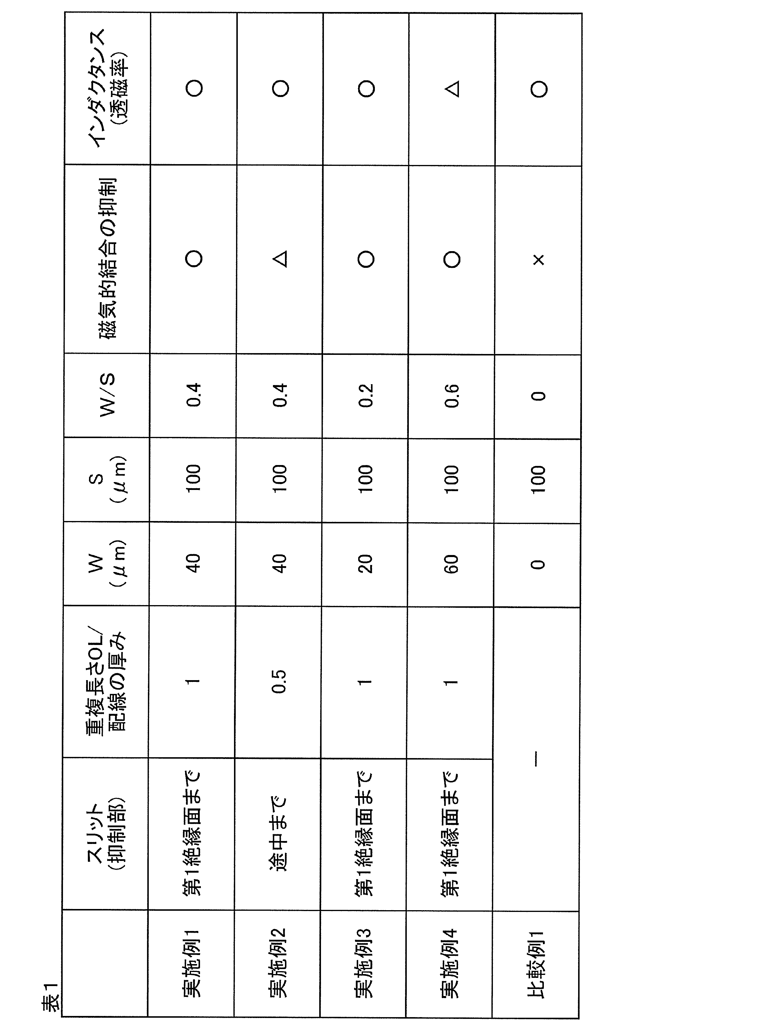
- Example 2 to Example 4 A magnetic wiring circuit board 1 was obtained in the same manner as in Example 1 except that the shape, dimensions, and the like of the suppressing portion 5 were changed according to Table 1.
- Comparative Example 1 The magnetic wiring circuit board 1 before forming the suppressing portion 5 shown in FIG. 3B (during manufacturing) was obtained as it is as the magnetic wiring circuit board 1 of Comparative Example 1.
- the magnetic wiring circuit board 1 does not include the suppression unit 5.
- the first wiring 41 of the first wiring 3A and one end in the second direction of the second wiring portion 42 are connected by another wiring, and the second wiring is short-circuited with the first wiring 3A.
- 3 (3B) was measured, and the difference between this value and the above-described reference inductance was determined. This was divided by the reference inductance to obtain the first rate of change of inductance.
- the first wiring 41 of the third wiring 3 (3C) and the one end portion in the second direction of the second wiring portion 42 are connected by another wiring, and the third wiring 3C is short-circuited (that is, In the state where both the first wiring 3A and the third wiring 3C located on both sides in the first direction of the second wiring 3B are short-circuited), the inductance of the second wiring 3B is measured, and this value and the above-mentioned reference The difference from the inductance was obtained. This was divided by the reference inductance to determine the second rate of change in inductance.
- the area occupied by the second wiring 3B and the magnetic layer 4 adjacent to one side in the first direction in the magnetic wiring circuit boards 1 of Examples 1 and 2 and Comparative Example 1. (In other words, the area occupied by the inductor by the second wiring 3B and the magnetic layer 4 corresponding to the second wiring 3B) (however, if there is a slit 25, the area obtained by subtracting the occupied area) IS was obtained. The inductance density was obtained by dividing the above-described reference inductance by this occupied area.
- FIG. 11 shows the relationship between the first change rate and the second change rate of inductance and the inductance density.
- a single mark ( ⁇ in Example 1) is a plot of the first change rate of inductance and the corresponding inductance density.
- a double mark ( ⁇ in Example 1) is a plot of the second change rate of inductance and the corresponding inductance density.
- Naka black (in Example 1, ⁇ ) is a plot of the rate of change of the reference inductance (ie, zero) and the corresponding inductance density.
- FIG. 11 shows that the magnetic coupling between the wirings 3 is more strongly affected as the first change rate and the second change rate of the inductance are higher.
- FIG. 12 shows that the magnetic coupling between the wirings 3 is more strongly influenced as the inductance change rate is higher.
- the suppression portion 5 reaches the first insulating surface 6.
- the suppression portion 5 reaches the middle of the insulating layer 2 in the thickness direction. It can be seen that the influence of the magnetic coupling between them is smaller.
- the magnetic wiring circuit board is used for, for example, wireless power transmission (wireless power feeding and / or wireless power receiving), wireless communication, a sensor, a passive component, and the like.
Landscapes
- Engineering & Computer Science (AREA)
- Power Engineering (AREA)
- Microelectronics & Electronic Packaging (AREA)
- Physics & Mathematics (AREA)
- Electromagnetism (AREA)
- Manufacturing & Machinery (AREA)
- Structure Of Printed Boards (AREA)
- Shielding Devices Or Components To Electric Or Magnetic Fields (AREA)
- Parts Printed On Printed Circuit Boards (AREA)
- Laminated Bodies (AREA)
- Coils Or Transformers For Communication (AREA)
- Insulated Metal Substrates For Printed Circuits (AREA)
- Soft Magnetic Materials (AREA)
Abstract
磁性配線回路基板は、絶縁層と、絶縁層の厚み方向一方面において、厚み方向と直交する直交方向に互いに間隔を隔てて配置される複数の配線部と、絶縁層の厚み方向一方面に複数の配線部を埋設するように配置される磁性層であって、磁性層の厚み方向一方面が複数の配線部の厚み方向一方面に対して厚み方向一方側に間隔を隔てて配置される磁性層と、 互いに隣り合う少なくとも2つの配線部間の磁性層において、磁性層の厚み方向一方面から、少なくとも2つの配線部の厚み方向一方面の間を結ぶ仮想線よりも厚み方向他方側に向かって延びるように形成され、少なくとも2つの配線部の磁気的結合を抑制する抑制部とを備える。
Description
本発明は、磁性配線回路基板に関する。
従来、複数の配線と、これを埋設する磁性層とを備える磁性配線回路基板が知られている(例えば、特許文献1参照。)。
しかるに、特許文献1に記載されるような磁性配線回路基板では、隣り合う配線同士は、それらの間を充填する磁性層を介して磁気的に結合し易い。そのため、一方の配線に電流を流すと、これに伴って、一方の配線の周囲に磁界が発生し、この磁界が、他方の配線に意図しない電流を生じさせ、つまり、ノイズを生じる(クロストークが発生する)という不具合がある。また、他方の配線に電流を流すときにも、上記と同様に、磁界の発生に起因して、一方の配線に意図しない電流が発生する不具合がある。
本発明は、隣り合う配線部におけるノイズの発生を抑制することのできる磁性配線回路基板を提供する。
本発明(1)は、絶縁層と、前記絶縁層の厚み方向一方面において、前記厚み方向と直交する直交方向に互いに間隔を隔てて配置される複数の配線部と、前記絶縁層の厚み方向一方面に前記複数の配線部を埋設するように配置される磁性層であって、前記磁性層の厚み方向一方面が前記複数の配線部の前記厚み方向一方面に対して前記厚み方向一方側に間隔を隔てて配置される磁性層と、互いに隣り合う少なくとも2つの前記配線部間の前記磁性層において、前記磁性層の前記厚み方向一方面から、前記少なくとも2つの前記配線部の前記厚み方向一方面の間を結ぶ仮想線よりも厚み方向他方側に向かって延びるように形成され、前記少なくとも2つの前記配線部の磁気的結合を抑制する抑制部とを備える、磁性配線回路基板を含む。
この磁性配線回路基板によれば、磁性層が、磁性層の厚み方向一方面から、少なくとも2つの配線部の厚み方向一方面の間を結ぶ仮想線よりも厚み方向他方側に向かって延びるので、隣り合う配線部の磁気的結合を抑制することができる。そのため、隣り合う配線部におけるノイズの発生を抑制することができる。
本発明(2)は、前記抑制部は、前記絶縁層の前記厚み方向一方面に至っている、(1)に記載の磁性配線回路基板を含む。
この磁性配線回路基板によれば、抑制部は、絶縁層の厚み方向一方面に至っているので、配線部の磁気的結合をより確実に抑制して、配線部におけるノイズの発生をより確実に抑制することができる。
本発明(3)は、前記抑制部は、前記磁性層に形成されるスリットである、(1)または(2)に記載の磁性配線回路基板を含む。
この磁性配線回路基板では、抑制部がスリットであるので、構成が簡易である。
本発明(4)は、前記抑制部における前記直交方向長さWの、前記少なくとも2つの前記配線部間の前記直交方向長さSに対する比(W/S)が、0.4以下である、(1)~(3)のいずれか一項に記載の磁性配線回路基板を含む。
抑制部における直交方向長さWの、複数の配線部間の直交方向長さSに対する比が、高い場合には、配線部間における比透磁率が過度に低下してしまい、磁性配線回路基板のインダクタンスが低下し易い。
しかし、この磁性配線回路基板では、抑制部における直交方向長さWの、複数の配線部間の直交方向長さSに対する比が、0.4以下と低いので、配線部間における比透磁率の過度の低下を抑制して、高いインダクタンスを確保することができる。
本発明によれば、抑制部によって、隣り合う配線部の磁気的結合を抑制して、隣り合う配線部におけるノイズの発生を抑制することができる。
<一実施形態>
本発明の配線回路基板の一実施形態である配線回路基板1を、図1および図2を参照して説明する。
本発明の配線回路基板の一実施形態である配線回路基板1を、図1および図2を参照して説明する。
磁性配線回路基板1は、厚み方向に互いに対向する厚み方向一方面および他方面を有し、面方向(厚み方向に直交する方向)(後述する第1方向および第2方向を含む面方向)に延びるシート形状を有する。
磁性配線回路基板1は、絶縁層2と、複数の配線3と、磁性層4と、抑制部5とを備える。
絶縁層2は、面方向に延びるシート形状を有する。絶縁層2は、厚み方向一方面である第1絶縁面6および他方面である第2絶縁面7を有する。絶縁層2は、次に説明する複数の配線3を支持する支持材であり、ひいては、磁性配線回路基板1を支持する支持層でもある。また、絶縁層2は、可撓性を有する。絶縁層2の材料としては、例えば、ポリイミド樹脂、ポリエステル樹脂、アクリル樹脂などの樹脂材料が挙げられる。また、絶縁層2は、単層および複層のいずれであってもよい。絶縁層2の厚みは、特に限定されず、例えば、1μm以上、1000μm以下である。
配線3は、絶縁層2の第1絶縁面6において、第1方向(図2における左右方向に相当し、面方向に含まれる方向)に互いに間隔を隔てて複数配置されている。図1に示すように、例えば、配線3は、第1の配線3Aと、第2の配線3Bと、第3の配線3Cとを、第1方向に間隔を隔てて並列配置されている。第1の配線3Aと、第2の配線3Bと、第3の配線3Cとは、第1方向一方側から第2方向側に向かって順に配置されている。
複数の配線3のそれぞれの平面視(厚み方向に見たときの)形状としては、例えば、略U形状である。複数の配線3のそれぞれは、厚み方向および第1方向に直交する第2方向(図2における紙面奥行き方向に相当する方向)に延びる複数の配線部の一例としての第1配線部41および第2配線部42と、第1配線部41および第2配線部42の第2方向一端部を接続する接続配線部43とを一体的に備える。
第1配線部41および第2配線部42は、第1方向(所定方向の一例)に間隔を隔てて対向配置されている。また、第1配線部41および第2配線部42は、第2方向に直交する断面視(第1方向および厚み方向に沿う切断面)(図2に示される切断面)において、間隔を隔てて隣り合っている。
なお、第1配線部41および第2配線部42は、配線3が複数設けられていることから、磁性配線回路基板1において、それぞれ、複数設けられている。
第1配線部41および第2配線部42のそれぞれの断面視(詳しくは、厚み方向および第1方向に沿って切断したときの断面視)形状としては、特に限定されず、例えば、略矩形状などが挙げられる。
第1配線部41および第2配線部42のそれぞれは、絶縁層2の第1絶縁面6に対して厚み方向一方側に間隔を隔てて対向配置される厚み方向一方面である第1配線面8と、絶縁層2の第1絶縁面6に接触する第2配線面9と、第1配線面8および第2配線面9の第1方向両端縁を連結する側面である第3配線面10とを一体的に備える。
第1配線面8は、第1方向に沿う平坦面である。
第2配線面9は、第1配線面8に平行する平坦面である。
第3配線面10は、厚み方向に沿って延びる。第3配線面10は、第1配線部41および第2配線部42のそれぞれに2つ備えられる。2つの第3配線面10は、第1方向に間隔を隔てて対向配置される。
接続配線部43は、第1配線部41および第2配線部42のそれぞれと同一の断面視形状を有する。
配線3の材料としては、例えば、銅などの金属(導体)が挙げられる。
配線3の厚みは、例えば、10μm以上、好ましくは、30μm以上であり、また、例えば、500μm以下、好ましくは、250μm以下である。第1配線部41および第2配線部42の幅は、例えば、20μm以上、2000μm以下である。第1配線部41および第2配線部42間の間隔は、例えば、20μm以上、好ましくは、50μm以上であり、また、例えば、2000μm以下、好ましくは、1500μm以下である。
配線3(第1配線部41および第2配線部42)の厚みの、第1配線部41および第2配線部42の幅に対する比(厚み/幅)は、例えば、0.005以上、好ましくは、0.015以上であり、また、例えば、25以下、好ましくは、12.5以下である。配線3の厚みの、第1配線部41および第2配線部42間の間隔に対する比(厚み/間隔)は、例えば、0.005以上、好ましくは、0.02以上であり、また、例えば、25以下、好ましくは、5以下である。
なお、配線3は、上記した絶縁層2とともに、配線回路基板15に備えられる。つまり、配線回路基板15は、絶縁層2と、複数の配線3とを備える。好ましくは、配線回路基板15は、絶縁層2と、複数の配線3とのみからなる。
磁性層4は、面方向に延びるシート形状を有する。磁性層4は、絶縁層2の第1絶縁面6に、複数の配線3を埋設するように配置されている。磁性層4は、第1磁性面11と、第1磁性面11の厚み方向他方側に間隔を隔てて配置される第2磁性面12とを有する。
第1磁性面11は、少なくとも第1配線部41および第2配線部42の第1配線面8に対して厚み方向一方側に間隔を隔てて配置されている。具体的には、第1磁性面11は、第1配線部41および第2配線部42に対応して厚み方向一方側に向かって隆起する複数の凸部13と、互いに隣り合う凸部13の間に配置され、凸部13に対して厚み方向他方側に向かって沈下する凹部14とを有する。凹部14(より具体的には、凹部14の厚み方向他端縁)は、第1配線部41および第2配線部42の第1配線面8の間を結ぶ仮想線ILよりも厚み方向一方側に間隔に隔てて位置している。
第2磁性面12は、絶縁層2において配線3から露出する第1絶縁面6と、配線3の第1配線面8および第3配線面10とを被覆している。
磁性層4の材料としては、例えば、磁性粒子および樹脂成分を含有する磁性組成物などが挙げられる。磁性粒子としては、例えば、磁気特性の観点から、センダストなどの軟磁性粒子が挙げられる。樹脂成分としては、例えば、エポキシ樹脂、硬化剤および硬化促進剤を含有するエポキシ樹脂組成物などの熱硬化性樹脂が挙げられる。なお、このような磁性組成物は、例えば、特開2017-005115号公報、特開2015-092543号公報などに記載されている。
磁性粒子の磁性層4における含有割合は、例えば、50体積%以上、好ましくは、55体積%以上であり、また、例えば、95体積%以下、好ましくは、90体積%以下である。
磁性層4の比透磁率は、例えば、3以上、好ましくは、5以上、より好ましくは、10以上であり、また、例えば、1000以下である。
抑制部5は、互いに隣り合う2つの配線部の磁気的結合を抑制する。抑制部5は、互いに隣り合う2つの配線3(一の配線3および他の配線3)において、一の配線3の第2配線部42と、一の配線3に隣り合う他の配線3の第1配線部41の間の磁性層4において、磁性層4の第1磁性面11から、第1配線部41および第2配線部42の第1配線面8の間を結ぶ仮想線ILよりも厚み方向他方側に延びるように形成されている。具体的には、抑制部5は、第1の配線3Aの第2配線部42と、第2の配線3Bの第1配線部41との間、および、第2の配線3Bの第2配線部42と、第3の配線3Cの第1配線部41との間に、形成されている。
また、抑制部5は、磁性層4の第1磁性面11から、絶縁層2の第1絶縁面6に至っている。
具体的には、抑制部5は、磁性層4に形成されるスリット(空隙部、隙間、開口部)25である。好ましくは、抑制部5は、スリット25のみからなる(後述する図6に示す変形例のように、充填部20を備えない。)。また、抑制部5は、磁性層4の凹部14から、厚み方向に沿って延びる断面略直線形状を有する。つまり、抑制部5は、その幅(第1方向長さ)Wが、厚み方向において同一である形状を有する。また、抑制部5は、断面(厚み方向および第1方向に沿う断面)視において、磁性層4を第1方向において分断(隔絶)している。
抑制部5は、第2方向に沿って、互いに隣り合う2つの配線部と平行するように、それらの間に形成されている。抑制部5は、例えば、一の配線3の第2配線部42と、他の配線3の第1配線部41とに沿う平面視略ストレート形状を有する。
抑制部5の幅(第1方向長さ)Wの、互いに隣り合う第1配線部41および第2配線部42間の間隔Sに対する比(W/S)は、例えば、0.7以下、好ましくは、0.5以下、より好ましくは、0.4以下、さらに好ましくは、0.3以下、とりわけ好ましくは、0.2以下、最も好ましくは、0.1以下であり、また、例えば、0.01以上である。
上記した比(W/S)が上記した上限以下であれば、配線3間における比透磁率の過度の低下を抑制して、磁性配線回路基板1における高いインダクタンスを確保することができる。
上記した比(W/S)が上記した上限以下であれば、配線3間における比透磁率の過度の低下を抑制して、磁性配線回路基板1における高いインダクタンスを確保することができる。
とりわけ、比(W/S)が0.4超過であれば、配線3間の磁気的結合を抑制する効果を得られず、一方で、インダクタンス密度のみが低下してしまう傾向があるところ、比(W/S)が0.4以下であれば、上記したインダクタンス密度のみの低下を抑制することができる。
具体的には、抑制部5の第1方向長さ(幅)Wは、例えば、100μm以下、好ましくは、80μm以下、より好ましくは、60μm以下であり、また、例えば、1μm以上である。
なお、抑制部5の厚み方向長さは、凹部14における磁性層4の厚みと同一である。
また、抑制部5における比透磁率は、抑制部5がスリット25であり、抑制部5に空気が存在する場合、実質的に1(詳しくは、真空の比透磁率1に近似する値)である。
磁性配線回路基板1の厚みは、その最大厚みとして、例えば、30μm以上、好ましくは、50μm以上であり、また、例えば、1000μm以下、好ましくは、800μm以下である。
次に、この磁性配線回路基板1の製造方法を、図3A~図3Cを参照して説明する。
図3Aに示すように、まず、絶縁層2および配線3を備える配線回路基板15を準備する。
続いて、磁性シート16を準備する。例えば、上記した磁性粒子および樹脂成分(好ましくは、Bステージの熱硬化性樹脂)を含有する磁性組成物から、シート形状に形成して、磁性シート16を準備する。
その後、図3Aの矢印で示すように、磁性シート16によって、配線回路基板15における複数の配線3を埋設する。例えば、磁性シート16が、Bステージの熱硬化性樹脂を含む場合には、磁性シート16を配線回路基板15に対して熱プレスする。
これにより、磁性シート16を、配線3(少なくとも第1配線部41および第2配線部42)に対応する形状に形成(成型)する。つまり、磁性シート16から、磁性層4を形成する。
なお、この磁性層4には、まだ、抑制部5が形成されていない。
図3Cに示すように、磁性層4に、抑制部5を形成する。
磁性層4に抑制部5を形成するには、例えば、切削装置(あるいは切断装置)が用いられる。
切削装置として、例えば、ダイシング装置などの、磁性層4と物理的に接触する接触式切削装置、例えば、レーザー装置などの、磁性層4と物理的に接触しない非接触式切削装置などが挙げられる。
切削装置として、形状制御の精度の観点からは、好ましくは、接触式切削装置が挙げられ、作業時間(タクトタイム)の短縮の観点からは、好ましくは、非接触式切削装置が挙げられる。
接触式切削装置の一例であるダイシング装置は、支持台(図示せず)と、これと間隔を隔てて対向配置されるダイシングソー17と、これを移動させる移動装置(図示せず)とを備える。
ダイシングソー17としては、例えば、円盤形状を有するダイシングブレードなどが挙げられる。
ダイシング装置で抑制部5を形成するには、まず、配線回路基板15および磁性層4をダイシング装置の支持台(図示せず)に設置する。これにより、ダイシングソー17は、磁性層4の厚み方向一方側に間隔を隔てて配置される。続いて、ダイシングソー17の周端を磁性層4の第1磁性面11(具体的には、凹部14)に接触させる。
続いて、ダイシングソー17を、その周端が絶縁層2の第1絶縁面6に至るまで、厚み方向他方側に移動(引き下げる)。その後、ダイシングソー17を、第2方向に沿って移動させる。これによって、スリット25である抑制部5が第2方向に沿って形成される。
これによって、配線回路基板15、磁性層4および抑制部5を備える磁性配線回路基板1が得られる。
その後、磁性層4がBステージの熱硬化性樹脂を含む場合には、必要により、磁性層4を、例えば、加熱により、Cステージ化(完全硬化)させる。
この磁性配線回路基板1は、例えば、無線電力伝送(無線給電および/または無線受電)、無線通信、センサ、受動部品などに用いられる。
そして、この磁性配線回路基板1によれば、磁性層4が、磁性層4の第1磁性面11から、互いに隣り合う2つの配線3(一の配線3の第2配線部42、および、他の配線3の第1配線部41)の第1配線面8の間を結ぶ仮想線ILよりも厚み方向他方側に向かって延びている。そのため、2つの配線3の磁気的結合を抑制することができる。そのため、2つの配線3におけるノイズの発生を抑制することができる。
また、この磁性配線回路基板1によれば、抑制部5は、絶縁層2の第1絶縁面6に至っている。そのため、2つの配線3の磁気的結合をより確実に抑制して、2つの配線3(一の配線3の第2配線部42、および、他の配線3の第1配線部41)におけるノイズの発生をより確実に抑制することができる。
さらに、この磁性配線回路基板1では、抑制部5が、スリット25であるので、簡単な構成で、2つの配線3(一の配線3の第2配線部42、および、他の配線3の第1配線部41)におけるノイズの発生を抑制することができる。
しかるに、抑制部5の幅Wの、複数の配線3間の間隔Sに対する比が、高い場合には、配線3間における比透磁率が過度に低下してしまい、磁性配線回路基板1のインダクタンスが低下し易い。また、配線3間における磁性層4を過度に除去することとなり、その結果、一の配線3の第2配線部42から生じる磁界が他の配線3の第1配線部41へも広がってしまうことで、配線3間での磁気的結合を強めることとなる。
しかし、この磁性配線回路基板1では、抑制部5の幅Wの、複数の配線3間の間隔Sに対する比が、0.4以下と低ければ、配線3間における比透磁率の過度の低下を抑制して、高いインダクタンスを確保することができる。
<変形例>
以下の各変形例において、上記した第1実施形態と同様の部材および工程については、同一の参照符号を付し、その詳細な説明を省略する。また、各変形例は、特記する以外、第1実施形態と同様の作用効果を奏することができる。さらに、第1実施形態およびその変形例を適宜組み合わせることができる。
以下の各変形例において、上記した第1実施形態と同様の部材および工程については、同一の参照符号を付し、その詳細な説明を省略する。また、各変形例は、特記する以外、第1実施形態と同様の作用効果を奏することができる。さらに、第1実施形態およびその変形例を適宜組み合わせることができる。
図2に示すように、一実施形態では、抑制部5は、磁性層4の第1磁性面11から、絶縁層2の第1絶縁面6に至っている。
しかし、図4に示すように、この変形例では、抑制部5は、絶縁層2の第1絶縁面6に至っておらず、第1絶縁面6と間隔が隔てられている。具体的には、抑制部5は、第1磁性面11から凹む抑制凹部である。抑制部5は、厚み方向一方側に向かって開口されている。抑制部5は、上記した仮想線ILよりも、厚み方向他方側に位置する底部18を有する。
底部18は、仮想線ILと、磁性層2の第1絶縁面6との間に位置している。
抑制部5の深さは、底部18が仮想線ILより厚み方向他方側に位置すれば特に限定されない。底部18と仮想線ILとの距離Lの、配線3の厚みに対する比(距離L/配線3の厚み)が、例えば、0.1以上、好ましくは、0.2以上であり、また、例えば、1未満、好ましくは、0.9以下である。
比が上記した下限以上であれば、互いに隣り合う配線3間の磁気的結合を有効に抑制することができる。比が上記した上限以下であれば、磁性層4の強度を確保することができる。
図2に示すように、一実施形態では、磁性層4は、配線3の第1配線面8および第3配線面10に接触している。つまり、磁性層4は、第1配線面8および第3配線面10に直接配置されている。
しかし、図5に示すように、磁性層4は、配線3の第1配線面8および第3配線面10に接触せず、磁性層4は、第1配線面8および第3配線面10に間接的に配置されていてもよい。
この変形例では、磁性層4および配線3の間に、第2絶縁層19が介在している。
第2絶縁層19は、配線3の第1配線面8および第3配線面10に沿う薄膜形状を有する。第2絶縁層19は、例えば、磁性を有さない。具体的には、第2絶縁層19の材料としては、例えば、磁性粒子を含有しない樹脂材料などが挙げられる。第2絶縁層19の樹脂材料は、絶縁層2で例示した樹脂材料と同様である。第2絶縁層19の厚みは、例えば、10μm以下、0.1μm以上である。
一実施形態では、図2に示すように、抑制部5は、スリット25のみからなるが、例えば、図6に示すように、抑制部5は、スリット25、および、スリット25に充填される充填部20を備えることもできる。この変形例では、抑制部5が、好ましくは、スリット25および充填部20のみからなる。
充填部20の材料としては、例えば、低透磁性材料などが挙げられる。低透磁性材料としては、例えば、磁性粒子を含有しない樹脂材料などが挙げられる。
好ましくは、一実施形態のように、図2に示すように、抑制部5がスリット25のみからなる。一実施形態によれば、抑制部5の比透磁率を、図6に示す充填部20をさらに含む抑制部5に比べて、確実に、低く設定することができ、そのため、配線3間の磁気的結合を有効に抑制することができる。
また、絶縁層2は、磁性粒子を含有し、磁性を有する磁性絶縁層であってもよい。
図3Aおよび図3Bに示すように、一実施形態では、磁性層4を磁性シート16から形成しているが、例えば、磁性組成物のワニスを調製し、これを塗布して、磁性層4を形成することもできる。
また、図3Bおよび図3Cに示すように、一実施形態では、磁性層4および抑制部5を別々の工程で形成している。しかし、図示しないが、一度の工程で形成することもできる。例えば、抑制部5と同一形状を有する壁部材(あるいはポスト)を2つの配線3間における第1絶縁面6に設置し、続いて、壁部材に対応する形状で、磁性層4を形成し、その後、壁部材を除去する(例えば、厚み方向一方側に向けて引き抜く)。これにより、磁性層4および抑制部5を一度に形成する。
一実施形態では、図2に示すように、抑制部5は、磁性層4の第1磁性面11から、厚み方向に沿って延びる断面略直線形状を有する。しかし、抑制部5(スリット25)の断面視形状は、これに限定されない。例えば、図7に示すように、開口面積(あるいは第1方向における対向長さ)が厚み方向他方側に向かって次第に小さく(狭く)なるテーパー形状であってもよい。
この場合には、抑制部5の幅Wは、抑制部5において仮想線IL上の長さとして定義される。抑制部5の幅Wは、W/Sが、例えば、0.4以下を満足するように、調整されれば、上記と同様の作用効果(配線3間における比透磁率の過度の低下の抑制)を奏することができる。
一実施形態では、図1に示すように、抑制部5は、互いに隣り合う2つの配線3の間に形成されているが、例えば、図8に示すように、1つの配線3における2つの配線部、すなわち、第1配線部41および第2配線部42の間に配置されていてもよい。
さらには、図9に示すように、互いに隣り合う2つの配線3の間、および、1つの配線3における第1配線部41および第2配線部42の間の両方に、配置されていてもよい。
なお、図示しないが、抑制部5は、上記で定義される幅Wよりも広く、仮想線ILよりも厚み方向他方側に配置される幅広部を有することができる。幅広部の形状は、特に限定されず、例えば、略円弧形状、略波形状などを含む。幅広部の幅(第2幅、第1方向長さ)は、例えば、上記した幅(第1幅)Wに対して、例えば、1.4以下、また、1超過である。
一実施形態では、抑制部5を形成した後、磁性層4のCステージ化を実施しているが、その順序は、逆であってもよい。
例えば、配線3のパターン形状は、特に限定されず、例えば、略コイル形状、略ループ形状、略S形状などを含む。
以下に実施例および比較例を示し、本発明をさらに具体的に説明する。なお、本発明は、何ら実施例および比較例に限定されない。また、以下の記載において用いられる配合割合(割合)、物性値、パラメータなどの具体的数値は、上記の「発明を実施するための形態」において記載されている、それらに対応する配合割合(割合)、物性値、パラメータなど該当記載の上限(「以下」、「未満」として定義されている数値)または下限(「以上」、「超過」として定義されている数値)に代替することができる。
実施例1
図1および図3A参照に示すように、絶縁層2と、複数の配線3とを備える配線回路基板15を準備した。
図1および図3A参照に示すように、絶縁層2と、複数の配線3とを備える配線回路基板15を準備した。
配線回路基板15において、絶縁層2は、ポリイミド樹脂からなり、厚みが5μmである。配線回路基板15において、複数の配線3は、銅からなり、厚みが100μmである。複数の配線3(第1の配線3A、第2の配線3Bおよび第3の配線3C)のそれぞれは、第1配線部41、第2配線部42および接続配線部43を有する。各配線3において、第1配線部41および第2配線部42は、それぞれ、幅が300μm、間隔が300μmである。一の配線3の第2配線部42、および、他の配線3の第1配線部41の間隔Sは、100μmである。
別途、磁性シート16を準備した。
磁性シート16は、センダストを60容積%、熱硬化性樹脂(エポキシ樹脂組成物)を40容積%含有する磁性組成物から形成した。
図3Bに示すように、その後、磁性シート16を配線回路基板15に対して熱プレスして、磁性層4を形成した。
その後、図3Bおよび図3Cに示すように、ダイシングソー17により、磁性層4に、磁性層4の第1磁性面11から、絶縁層2の第1絶縁面6に至るスリット25を形成して、抑制部5を形成した。
抑制部5の幅Wは、40μmである。なお、抑制部5の幅Wに対する、複数の配線3間隔Sの比(W/S)は、0.4であった。
これにより、磁性配線回路基板1を得た。
実施例2~実施例4
抑制部5の形状、寸法等を表1に従って変更した以外は、実施例1と同様に処理して、磁性配線回路基板1を得た。
抑制部5の形状、寸法等を表1に従って変更した以外は、実施例1と同様に処理して、磁性配線回路基板1を得た。
比較例1
図3Bに示す、抑制部5を形成する前(製造途中)の磁性配線回路基板1をそのまま比較例1の磁性配線回路基板1として得た。
図3Bに示す、抑制部5を形成する前(製造途中)の磁性配線回路基板1をそのまま比較例1の磁性配線回路基板1として得た。
つまり、磁性配線回路基板1は、抑制部5を備えない。
(評価1)
磁気的結合の抑制(インダクタンスの第1変化率および第2変化率)
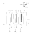
実施例1、2および比較例1の磁性配線回路基板1のそれぞれにおける第2の配線3Bにおける第1配線41および第2配線部42の第2方向一端部を、インピーダンス・アナライザ(Agilent社製:4294A)に接続して、第1の配線3に隣接する他の配線3のインダクタンスを測定し、このインダクタンスを参照インダクタンスとした。
磁気的結合の抑制(インダクタンスの第1変化率および第2変化率)
実施例1、2および比較例1の磁性配線回路基板1のそれぞれにおける第2の配線3Bにおける第1配線41および第2配線部42の第2方向一端部を、インピーダンス・アナライザ(Agilent社製:4294A)に接続して、第1の配線3に隣接する他の配線3のインダクタンスを測定し、このインダクタンスを参照インダクタンスとした。
次いで、第1の配線3Aの第1配線41および第2配線部42の第2方向一端部を、別の配線で接続して、第1の配線3Aを短絡させた状態で、第2の配線3(3B)のインダクタンスを測定し、この値と、上記した参照インダクタンスとの差を求めた。これを参照インダクタンスで割って、インダクタンスの第1変化率を求めた。
さらに、第3の配線3(3C)の第1配線41および第2配線部42の第2方向一端部を、別の配線で接続して、第3の配線3Cを短絡させた状態(つまり、第2の配線3Bの第1方向両側に位置する第1の配線3Aおよび第3配線3Cをともに短絡させた状態)で、第2の配線3Bのインダクタンスを測定し、この値と、上記した参照インダクタンスとの差を求めた。これを参照インダクタンスで割って、インダクタンスの第2変化率を求めた。
併せて、図10の太破線で示すように、実施例1、2および比較例1の磁性配線回路基板1における第2の配線3Bとその第1方向一方側に隣接する磁性層4の占有面積(つまり、第2の配線3Bおよびそれに対応する磁性層4によるインダクタの占有面積)(但し、スリット25がある場合には、その占有面積を差し引いた面積)ISを求めた。この占有面積で、上記した参照インダクタンスを割って、インダクタンス密度を求めた。
インダクタンスの第1変化率および第2変化率と、インダクタンス密度との関係を図11に示す。
なお、図11中、一重マーク(実施例1では、○)は、インダクタンスの第1変化率およびそれに対応するインダクタンス密度のプロットである。二重マーク(実施例1では、◎)は、インダクタンスの第2変化率およびそれに対応するインダクタンス密度のプロットである。中黒(実施例1では、●)は、参照インダクタンスの変化率(つまり、ゼロ)およびそれに対応するインダクタンス密度のプロットである。
図11において、インダクタンスの第1変化率および第2変化率が高くなるほど、配線3間の磁気的結合が強く影響していることを示す。
(評価2)
磁気的結合の抑制(インダクタンスの変化率)
実施例1、3、4および比較例1の磁性配線回路基板1の第2変化率のおよびそれに対応するインダクタンス密度を求め、これらを、図12に示す。
磁気的結合の抑制(インダクタンスの変化率)
実施例1、3、4および比較例1の磁性配線回路基板1の第2変化率のおよびそれに対応するインダクタンス密度を求め、これらを、図12に示す。
図12において、インダクタンスの変化率が高くなるほど、配線3間の磁気的結合が強く影響していることを示す。
(考察1)
図11に示すように、実施例1、2および比較例1を比べると、抑制部5を備える実施例1および2は、それを備えない比較例1に比べて、配線3間の磁気的結合の影響が小さいことが分かる。
図11に示すように、実施例1、2および比較例1を比べると、抑制部5を備える実施例1および2は、それを備えない比較例1に比べて、配線3間の磁気的結合の影響が小さいことが分かる。
また、実施例1および2を比べると、抑制部5が第1絶縁面6に至るを実施例1は、抑制部5が絶縁層2の厚み方向途中まで至る実施例2に比べて、配線3間の磁気的結合の影響がより小さいことが分かる。
(考察2)
図12に示すように、実施例1、3および比較例1を比べると、W/Sが0から0.4に近接するにつれて、配線3間の磁気的結合の影響がより小さいことが分かる。
図12に示すように、実施例1、3および比較例1を比べると、W/Sが0から0.4に近接するにつれて、配線3間の磁気的結合の影響がより小さいことが分かる。
一方、実施例1および4を比べると、W/Sが0.4から0.6に向かって大きくなっても、配線3間の磁気的結合を抑制する効果はほぼなく、一方で、インダクタンス密度のみが低下することが分かる。このことは、抑制部5の幅Wが過大となるため、配線3から生じる磁界が隣接する配線3へも広がり易くなることに起因すると考えられる。そのため、配線3間の磁気的結合の影響を有効に低減するには、W/Sが0.4以下であればよいことが分かる。
なお、上記発明は、本発明の例示の実施形態として提供したが、これは単なる例示に過ぎず、限定的に解釈してはならない。当該技術分野の当業者によって明らかな本発明の変形例は、後記請求の範囲に含まれる。
磁性配線回路基板は、例えば、無線電力伝送(無線給電および/または無線受電)、無線通信、センサ、受動部品などに用いられる。
1 磁性配線回路基板
2 絶縁層
4 磁性層
5 抑制部
6 第1絶縁面
8 第1配線面
20 充填部
25 スリット
41 第1配線部
42 第2配線部
11 第1磁性面
IL 仮想線
W 幅
S 配線間の間隔
2 絶縁層
4 磁性層
5 抑制部
6 第1絶縁面
8 第1配線面
20 充填部
25 スリット
41 第1配線部
42 第2配線部
11 第1磁性面
IL 仮想線
W 幅
S 配線間の間隔
Claims (4)
- 絶縁層と、
前記絶縁層の厚み方向一方面において、前記厚み方向と直交する直交方向に互いに間隔を隔てて配置される複数の配線部と、
前記絶縁層の厚み方向一方面に前記複数の配線部を埋設するように配置される磁性層であって、前記磁性層の厚み方向一方面が前記複数の配線部の前記厚み方向一方面に対して前記厚み方向一方側に間隔を隔てて配置される磁性層と、
互いに隣り合う少なくとも2つの前記配線部間の前記磁性層において、前記磁性層の前記厚み方向一方面から、前記少なくとも2つの前記配線部の前記厚み方向一方面の間を結ぶ仮想線よりも厚み方向他方側に向かって延びるように形成され、前記少なくとも2つの前記配線部の磁気的結合を抑制する抑制部と
を備えることを特徴とする、磁性配線回路基板。 - 前記抑制部は、前記絶縁層の前記厚み方向一方面に至っていることを特徴とする、請求項1に記載の磁性配線回路基板。
- 前記抑制部は、前記磁性層に形成されるスリットであることを特徴とする、請求項1に記載の磁性配線回路基板。
- 前記抑制部における前記直交方向長さWの、前記少なくとも2つの前記配線部間の前記直交方向長さSに対する比(W/S)が、0.4以下であることを特徴とする、請求項1に記載の磁性配線回路基板。
Priority Applications (4)
| Application Number | Priority Date | Filing Date | Title |
|---|---|---|---|
| KR1020207028405A KR102655610B1 (ko) | 2018-04-09 | 2019-04-02 | 자성 배선 회로 기판 |
| US17/044,448 US11006515B2 (en) | 2018-04-09 | 2019-04-02 | Magnetic wiring circuit board |
| CN201980022592.8A CN111919269B (zh) | 2018-04-09 | 2019-04-02 | 磁性布线电路基板 |
| EP19784782.5A EP3780032A4 (en) | 2018-04-09 | 2019-04-02 | Magnetic wiring circuit board |
Applications Claiming Priority (2)
| Application Number | Priority Date | Filing Date | Title |
|---|---|---|---|
| JP2018074801A JP7220948B2 (ja) | 2018-04-09 | 2018-04-09 | 磁性配線回路基板 |
| JP2018-074801 | 2018-04-09 |
Publications (1)
| Publication Number | Publication Date |
|---|---|
| WO2019198569A1 true WO2019198569A1 (ja) | 2019-10-17 |
Family
ID=68163577
Family Applications (1)
| Application Number | Title | Priority Date | Filing Date |
|---|---|---|---|
| PCT/JP2019/014644 Ceased WO2019198569A1 (ja) | 2018-04-09 | 2019-04-02 | 磁性配線回路基板 |
Country Status (7)
| Country | Link |
|---|---|
| US (1) | US11006515B2 (ja) |
| EP (1) | EP3780032A4 (ja) |
| JP (1) | JP7220948B2 (ja) |
| KR (1) | KR102655610B1 (ja) |
| CN (1) | CN111919269B (ja) |
| TW (1) | TWI784156B (ja) |
| WO (1) | WO2019198569A1 (ja) |
Cited By (1)
| Publication number | Priority date | Publication date | Assignee | Title |
|---|---|---|---|---|
| JP2025059727A (ja) * | 2023-09-29 | 2025-04-10 | 株式会社ダイヘン | トランス用のコイル基板 |
Families Citing this family (3)
| Publication number | Priority date | Publication date | Assignee | Title |
|---|---|---|---|---|
| JP7565721B2 (ja) * | 2020-07-27 | 2024-10-11 | 日東電工株式会社 | インダクタの製造方法 |
| JP7546397B2 (ja) | 2020-07-27 | 2024-09-06 | 日東電工株式会社 | インダクタ |
| WO2022092791A1 (ko) | 2020-10-27 | 2022-05-05 | 주식회사 엘지화학 | 이물제거장치 |
Citations (5)
| Publication number | Priority date | Publication date | Assignee | Title |
|---|---|---|---|---|
| JPH05152130A (ja) * | 1991-11-26 | 1993-06-18 | Matsushita Electric Ind Co Ltd | 複合インダクタおよびその製造方法 |
| JPH06302436A (ja) * | 1993-04-12 | 1994-10-28 | Tdk Corp | 積層型ノイズ吸収素子複合体 |
| JP2004363291A (ja) * | 2003-06-04 | 2004-12-24 | Murata Mfg Co Ltd | 積層型電子部品およびその製造方法 |
| JP2015092543A (ja) | 2013-10-01 | 2015-05-14 | 日東電工株式会社 | 軟磁性粒子粉末、軟磁性樹脂組成物、軟磁性フィルム、軟磁性フィルム積層回路基板および位置検出装置 |
| JP2017005115A (ja) | 2015-06-10 | 2017-01-05 | 日東電工株式会社 | コイルモジュールおよびその製造方法 |
Family Cites Families (20)
| Publication number | Priority date | Publication date | Assignee | Title |
|---|---|---|---|---|
| JPS5981022U (ja) * | 1982-11-24 | 1984-05-31 | ティーディーケイ株式会社 | 積層複合部品 |
| DE3776359D1 (en) * | 1986-02-13 | 1992-03-12 | Sony Corp | Duennschichtmagnetkopf. |
| JP3220981B2 (ja) | 1989-11-17 | 2001-10-22 | ティーディーケイ株式会社 | 混成集積回路部品の構造 |
| JP3200954B2 (ja) * | 1992-05-01 | 2001-08-20 | 株式会社村田製作所 | 複合電子部品 |
| JPH10270256A (ja) * | 1997-03-21 | 1998-10-09 | Taiyo Yuden Co Ltd | 電子部品 |
| KR20030043747A (ko) * | 2001-11-28 | 2003-06-02 | 후지 샤신 필름 가부시기가이샤 | 자기전사용 마스터 담체 및 자기전사방법 |
| JP2004079090A (ja) * | 2002-08-20 | 2004-03-11 | Hitachi Ltd | 記録再生分離型磁気ヘッド |
| JP4547889B2 (ja) * | 2003-10-21 | 2010-09-22 | Tdk株式会社 | 磁気結合素子 |
| JP2005333081A (ja) | 2004-05-21 | 2005-12-02 | Shinko Electric Ind Co Ltd | 基板、半導体装置及び基板の製造方法 |
| JP2006031756A (ja) * | 2004-07-12 | 2006-02-02 | Tdk Corp | 磁気記録媒体 |
| US6996892B1 (en) * | 2005-03-24 | 2006-02-14 | Rf Micro Devices, Inc. | Circuit board embedded inductor |
| CN100593362C (zh) * | 2005-07-04 | 2010-03-03 | 欧姆龙株式会社 | 电路基板、电子设备和电源装置 |
| TWI319581B (en) | 2006-08-08 | 2010-01-11 | Murata Manufacturing Co | Laminated coil component and method for manufacturing the same |
| KR100829569B1 (ko) * | 2006-10-18 | 2008-05-14 | 삼성전자주식회사 | 자구벽 이동을 이용한 반도체 장치 및 그의 제조방법 |
| JP2010028695A (ja) * | 2008-07-24 | 2010-02-04 | Murata Mfg Co Ltd | ノイズフィルタ部品及びコイル部品 |
| JP5134580B2 (ja) * | 2009-05-01 | 2013-01-30 | 日東電工株式会社 | 配線回路基板およびそれを備えた磁気ヘッド駆動装置 |
| CN103377795B (zh) * | 2012-04-24 | 2016-01-27 | 乾坤科技股份有限公司 | 电磁器件及其制作方法 |
| JP6377336B2 (ja) * | 2013-03-06 | 2018-08-22 | 株式会社東芝 | インダクタ及びその製造方法 |
| JP6125328B2 (ja) | 2013-05-27 | 2017-05-10 | 日東電工株式会社 | 軟磁性フィルム積層回路基板の製造方法 |
| KR102105396B1 (ko) | 2015-01-28 | 2020-04-28 | 삼성전기주식회사 | 칩 전자부품 및 칩 전자부품의 실장 기판 |
-
2018
- 2018-04-09 JP JP2018074801A patent/JP7220948B2/ja active Active
-
2019
- 2019-04-02 KR KR1020207028405A patent/KR102655610B1/ko active Active
- 2019-04-02 US US17/044,448 patent/US11006515B2/en active Active
- 2019-04-02 EP EP19784782.5A patent/EP3780032A4/en active Pending
- 2019-04-02 CN CN201980022592.8A patent/CN111919269B/zh active Active
- 2019-04-02 WO PCT/JP2019/014644 patent/WO2019198569A1/ja not_active Ceased
- 2019-04-08 TW TW108112099A patent/TWI784156B/zh active
Patent Citations (5)
| Publication number | Priority date | Publication date | Assignee | Title |
|---|---|---|---|---|
| JPH05152130A (ja) * | 1991-11-26 | 1993-06-18 | Matsushita Electric Ind Co Ltd | 複合インダクタおよびその製造方法 |
| JPH06302436A (ja) * | 1993-04-12 | 1994-10-28 | Tdk Corp | 積層型ノイズ吸収素子複合体 |
| JP2004363291A (ja) * | 2003-06-04 | 2004-12-24 | Murata Mfg Co Ltd | 積層型電子部品およびその製造方法 |
| JP2015092543A (ja) | 2013-10-01 | 2015-05-14 | 日東電工株式会社 | 軟磁性粒子粉末、軟磁性樹脂組成物、軟磁性フィルム、軟磁性フィルム積層回路基板および位置検出装置 |
| JP2017005115A (ja) | 2015-06-10 | 2017-01-05 | 日東電工株式会社 | コイルモジュールおよびその製造方法 |
Non-Patent Citations (1)
| Title |
|---|
| See also references of EP3780032A4 |
Cited By (2)
| Publication number | Priority date | Publication date | Assignee | Title |
|---|---|---|---|---|
| JP2025059727A (ja) * | 2023-09-29 | 2025-04-10 | 株式会社ダイヘン | トランス用のコイル基板 |
| JP7685571B2 (ja) | 2023-09-29 | 2025-05-29 | 株式会社ダイヘン | トランス用のコイル基板 |
Also Published As
| Publication number | Publication date |
|---|---|
| TWI784156B (zh) | 2022-11-21 |
| US20210037640A1 (en) | 2021-02-04 |
| KR20200140268A (ko) | 2020-12-15 |
| US11006515B2 (en) | 2021-05-11 |
| EP3780032A1 (en) | 2021-02-17 |
| TW201944436A (zh) | 2019-11-16 |
| EP3780032A4 (en) | 2021-12-29 |
| JP7220948B2 (ja) | 2023-02-13 |
| JP2019186365A (ja) | 2019-10-24 |
| CN111919269A (zh) | 2020-11-10 |
| KR102655610B1 (ko) | 2024-04-08 |
| CN111919269B (zh) | 2023-02-17 |
Similar Documents
| Publication | Publication Date | Title |
|---|---|---|
| US12087502B2 (en) | Inductor component | |
| WO2019198569A1 (ja) | 磁性配線回路基板 | |
| CN105870076B (zh) | 半导体封装结构 | |
| TW202006759A (zh) | 電感器 | |
| JP6478001B2 (ja) | 電子部品 | |
| JP2021052181A (ja) | インダクタ | |
| JP2021100098A (ja) | インダクタ | |
| WO2019235132A1 (ja) | 配線回路基板およびその製造方法 | |
| JP2012069815A (ja) | プリント回路板 | |
| WO2016059918A1 (ja) | 電子部品 | |
| KR101701063B1 (ko) | 공통모드필터 | |
| US7450397B2 (en) | Wiring board and circuit apparatus | |
| JP2021052180A (ja) | インダクタ | |
| JP7802505B2 (ja) | チップ型コイル部品 | |
| CN101510547B (zh) | 用于电感器的栅栏电磁箱 | |
| WO2019058967A1 (ja) | インダクタおよびその製造方法 | |
| US9648739B2 (en) | Electronic component mounting structure and printed wiring board | |
| WO2016149269A1 (en) | Comprehensive layout strategy for flip chipping integrated circuits | |
| US7816768B2 (en) | Semiconductor device including ground and power-supply planes and a dielectric layer between the ground and power-supply planes | |
| US20250292951A1 (en) | Coil component | |
| JP2015026747A (ja) | 樹脂多層基板 | |
| US11756717B2 (en) | Coil component | |
| KR20260015730A (ko) | 코일 부품 | |
| CN113709972A (zh) | 一种电路板及其制造方法、封装件 | |
| JP2007095755A (ja) | 半導体素子搭載用基板 |
Legal Events
| Date | Code | Title | Description |
|---|---|---|---|
| 121 | Ep: the epo has been informed by wipo that ep was designated in this application |
Ref document number: 19784782 Country of ref document: EP Kind code of ref document: A1 |
|
| NENP | Non-entry into the national phase |
Ref country code: DE |
|
| ENP | Entry into the national phase |
Ref document number: 2019784782 Country of ref document: EP Effective date: 20201109 |