WO2019198720A1 - Unité de capteur - Google Patents
Unité de capteur Download PDFInfo
- Publication number
- WO2019198720A1 WO2019198720A1 PCT/JP2019/015493 JP2019015493W WO2019198720A1 WO 2019198720 A1 WO2019198720 A1 WO 2019198720A1 JP 2019015493 W JP2019015493 W JP 2019015493W WO 2019198720 A1 WO2019198720 A1 WO 2019198720A1
- Authority
- WO
- WIPO (PCT)
- Prior art keywords
- pressure
- intake
- sensor
- casing
- passage
- Prior art date
- Legal status (The legal status is an assumption and is not a legal conclusion. Google has not performed a legal analysis and makes no representation as to the accuracy of the status listed.)
- Ceased
Links
Images


Classifications
-
- F—MECHANICAL ENGINEERING; LIGHTING; HEATING; WEAPONS; BLASTING
- F02—COMBUSTION ENGINES; HOT-GAS OR COMBUSTION-PRODUCT ENGINE PLANTS
- F02D—CONTROLLING COMBUSTION ENGINES
- F02D35/00—Controlling engines, dependent on conditions exterior or interior to engines, not otherwise provided for
-
- F—MECHANICAL ENGINEERING; LIGHTING; HEATING; WEAPONS; BLASTING
- F02—COMBUSTION ENGINES; HOT-GAS OR COMBUSTION-PRODUCT ENGINE PLANTS
- F02D—CONTROLLING COMBUSTION ENGINES
- F02D45/00—Electrical control not provided for in groups F02D41/00 - F02D43/00
-
- G—PHYSICS
- G01—MEASURING; TESTING
- G01K—MEASURING TEMPERATURE; MEASURING QUANTITY OF HEAT; THERMALLY-SENSITIVE ELEMENTS NOT OTHERWISE PROVIDED FOR
- G01K13/00—Thermometers specially adapted for specific purposes
- G01K13/02—Thermometers specially adapted for specific purposes for measuring temperature of moving fluids or granular materials capable of flow
-
- G—PHYSICS
- G01—MEASURING; TESTING
- G01L—MEASURING FORCE, STRESS, TORQUE, WORK, MECHANICAL POWER, MECHANICAL EFFICIENCY, OR FLUID PRESSURE
- G01L15/00—Devices or apparatus for measuring two or more fluid pressure values simultaneously
-
- G—PHYSICS
- G01—MEASURING; TESTING
- G01L—MEASURING FORCE, STRESS, TORQUE, WORK, MECHANICAL POWER, MECHANICAL EFFICIENCY, OR FLUID PRESSURE
- G01L19/00—Details of, or accessories for, apparatus for measuring steady or quasi-steady pressure of a fluent medium insofar as such details or accessories are not special to particular types of pressure gauges
- G01L19/14—Housings
Definitions
- the present invention relates to a sensor unit in which a plurality of pressure sensors capable of detecting air pressure are housed in a casing.
- Conventional throttle valve devices that control the flow rate of air supplied to an internal combustion engine mounted on a vehicle include, for example, a position sensor that detects the opening of a valve for opening and closing a flow path, An intake air temperature sensor for detecting the air temperature and an intake air pressure sensor for detecting the pressure of the air are provided, and various data detected by each sensor are used for combustion control of the internal combustion engine.
- a sensor unit is provided on the side of the throttle body, and an intake pressure sensor and an external air pressure sensor are housed inside the sensor body of the sensor unit.
- the intake pressure sensor is connected to the lower side of the circuit board, and the external air pressure sensor connected to the upper side of the circuit board is connected to the air outside the sensor unit (outside air) through the end protruding from the sensor body. The pressure is detected.
- the atmospheric pressure sensor and the intake pressure sensor are housed in two stages in the upper and lower stages inside the package, and the terminal arrangement portion of the terminal branched in a bifurcated manner Are each electrically connected. And this package is mounted in the engine room of the vehicle, the air taken in from the atmospheric pressure introduction path is led to the atmospheric pressure sensor, the intake air taken in from the intake pressure introduction path is led to the intake pressure sensor, Each pressure is detected.
- a general object of the present invention is to provide a sensor unit capable of improving the assembling property of a plurality of pressure sensors and reducing the manufacturing cost.
- the present invention relates to a sensor unit including a casing and at least two pressure sensors disposed inside the casing.
- the sensor unit includes a composite wiring member that extends in parallel to a reference wiring surface that is a plane on which a plurality of wirings to which two pressure sensors are electrically connected are arranged and connects the plurality of wirings to each other.
- the casing has an inner wall surface, and two pressure sensors are respectively disposed between the inner wall surface and the reference wiring surface, and are electrically connected to the wiring on the wiring side of the pressure sensor, The pressure sensitive parts of the two pressure sensors are exposed to a pressure sensitive space surrounded by at least a part of the inner wall surface and at least a part of the pressure sensor, respectively. It communicates with the outside of the casing.
- the casing has an inner wall surface, and the pressure sensor is disposed between the inner wall surface and the composite wiring member, The pressure sensor is electrically connected to the wiring of the composite wiring member. Further, the pressure sensitive part of the pressure sensor is exposed to a pressure sensitive space surrounded by at least a part of the inner wall surface and at least a part of the pressure sensor, and the pressure sensitive space passes through the pressure passage provided in the casing. Communicates with the outside of the casing.
- the two pressure sensors constituting the sensor unit can be attached to the composite wiring member from the same direction and electrically connected to the wiring arranged on the reference wiring surface, respectively.
- the connection work and assembly work can be simplified.
- the assembly of the sensor unit having a plurality of pressure sensors can be improved, and the atmospheric pressure sensor and the intake pressure sensor arranged in two upper and lower stages as in the pressure detection device of Japanese Patent Application Laid-Open No. 2001-174355 are provided.
- the terminal since it is not necessary to form the terminal into a bifurcated shape, it is possible to simplify the configuration and reduce the manufacturing cost.
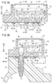
- FIG. 3A is a cross-sectional view of the sensor unit shown in FIG. 1
- FIG. 3B is a cross-sectional view taken along the line IIIB-IIIB of FIG. 3A
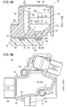
- 4A is a cross-sectional view taken along line IVA-IVA in FIG. 3A
- FIG. 4B is a front view of the throttle valve device shown in FIG. 1 as viewed from the sensor unit side.
- the throttle valve device (intake control device) 10 is mounted on, for example, a motorcycle, and as shown in FIGS. 1 and 2, between an inlet pipe connected to an internal combustion engine and an air duct into which outside air is introduced.
- a body 12 a shaft 14 rotatably supported by the body 12, a valve (valve element) 18 fixed to the shaft 14 and provided in an intake passage 16 of the body 12, and a side of the body 12
- a sensor unit 20 in which a plurality of sensors are housed.
- the body 12 is made of, for example, a metal material, and an intake passage 16 having a circular cross section extends from one end portion to the other end portion thereof, and has a cylindrical shape having the intake passage 16 therein at one end portion thereof.
- the intake pipe 22 protrudes.
- An air duct (not shown) is connected to the intake pipe 22 on the upstream side of the intake passage 16 to introduce outside air.
- the intake passage 16 has a downstream end opened to a first mounting surface 24 formed in a planar shape at the other end of the body 12.
- An inlet pipe (not shown) is connected to the first mounting surface 24 of the body 12 so that outside air is supplied from the inlet pipe to the internal combustion engine through the intake passage 16.
- a second mounting surface 26 (see FIG. 2) extending substantially in parallel with the extending direction (arrow A direction) of the intake passage 16 is formed on the side portion of the body 12, and the first opening opened substantially in the center.
- One end of the shaft 14 protrudes to the outside through the shaft hole 28, and an insertion hole 30 is formed that is located a predetermined distance away from the first shaft hole 28.
- the insertion hole 30 is formed substantially parallel to the first shaft hole 28 and penetrates to the intake passage 16 (see FIG. 3B).
- the second mounting surface 26 has a guide groove 34 that is close to the first shaft hole 28 and the insertion hole 30.
- the guide groove 34 is elongated in parallel with the direction in which the intake passage 16 extends, and is formed so as to be recessed to the intake passage 16 side with a predetermined depth.
- An intake pressure detection hole 36 communicating with the downstream side of 18 is formed.
- the second mounting surface 26 includes a seal groove 38 formed so as to surround the first shaft hole 28, the insertion hole 30, and the guide groove 34, and a seal ring (seal member) 40 is provided in the seal groove 38. .
- the seal ring 40 is formed of, for example, an elastic material and is provided so as to slightly protrude from the second mounting surface 26 in a state where the seal ring 40 is mounted in the seal groove 38, and the sensor unit 20 is provided on the second mounting surface of the body 12. When connected so as to oppose to 26, sealing is performed by being sandwiched between a unit mounting surface 66 and a second mounting surface 26 of the sensor unit 20 described later.
- the seal ring 40 has an annular first seal portion 42 formed so as to surround the outer peripheral side of the first shaft hole 28, and is adjacent to the first seal portion 42.
- a second seal portion 44 formed so as to surround the outside of the insertion hole 30 and a fourth seal portion 48 adjacent to the first and second seal portions 42 and 44 and surrounding the guide groove 34 are integrally formed.
- seal ring 40 is integrally formed with a third seal portion 46 that surrounds the surrounding surface 32 that is a surface on the outer edge side of the insertion hole 30 of the second mounting surface 26.
- the surrounding surface 32 is surrounded so as to be elongated in a direction orthogonal to the direction in which the intake passage 16 extends.
- a disc-shaped valve 18 is provided inside the intake passage 16 and is connected to a shaft 14 provided so that the central portion thereof is orthogonal to the extending direction of the intake passage 16 (the direction of arrow A).
- the shaft 14 is rotatably supported with respect to the body 12 via a bearing (not shown).
- One end of the shaft 14 projects outward from the second mounting surface 26 of the body 12, and the other end of the shaft 14 is in the body 12.
- the throttle drum 50 is connected so as to protrude to the opposite side.
- the accelerator wire (not shown) connected to the throttle drum 50 is pulled by the accelerator operation of the occupant in the vehicle, so that the shaft 14 and the valve 18 rotate by a predetermined angle against the spring force of the spring (not shown). To do.
- the sensor unit 20 includes, for example, a casing 52 formed of a resin material and formed in a bottomed box shape, and a bottom wall (inner wall surface) 54 of the casing 52 is formed. Is provided so as to face the second mounting surface 26 of the body 12, and a bolt 58 inserted through two holes 56 formed at the corners of the body 12 is screwed into a screw hole (not shown) of the body 12. Is fixed.
- the casing 52 has an opening 60 that opens to face the bottom wall 54 on the side opposite to the bottom wall 54 (in the direction of arrow B1), and a plate-like lid 62 is attached to the opening 60. Is done.
- the lid 62 is fixed to the opening end of the casing 52 by heat welding or the like, so that the opening 60 is closed, and the lid 62 is pressurized with external air pressure.
- An outside air intake port (introduction port) 64 for transmitting the gas to the inside 52 is opened (see FIGS. 1 and 4B).
- the bottom wall 54 of the casing 52 has a unit mounting surface (second mounting surface) 66 disposed so as to face the second mounting surface 26 of the body 12.
- a second shaft hole 68 (see FIG. 2) through which the other end of the shaft 14 is inserted, and a temperature protruding away from the second shaft hole 68 toward the body 12 (in the direction of arrow B2) Intake pressure opened in the vicinity of the detection tube 70, a communication groove 72 positioned on the outer edge side of the unit mounting surface 66 with respect to the temperature detection tube 70, and the second shaft hole 68 and the temperature detection tube 70.
- a detection passage 74 is provided in the vicinity of the detection tube 70, a communication groove 72 positioned on the outer edge side of the unit mounting surface 66 with respect to the temperature detection tube 70, and the second shaft hole 68 and the temperature detection tube 70.
- an opening sensor (valve opening sensor) 76 capable of detecting the opening degree (rotation amount) of the shaft 14 is accommodated in the second shaft hole 68, and the sensor unit 20 is connected to the body 12.
- the opening sensor 76 capable of detecting the opening degree (rotation amount) of the shaft 14 is accommodated in the second shaft hole 68, and the sensor unit 20 is connected to the body 12.
- the temperature detection tube 70 is formed in a hollow shape, and its distal end projects into the intake passage 16 through the insertion hole 30 of the body 12, and its proximal end extends through the bottom wall 54 of the casing 52.
- An intake air temperature sensor 78 (see FIG. 3B), which will be described later, is accommodated in the interior through the interior.
- the communication groove 72 is formed in a slit shape that is long in the direction orthogonal to the extending direction of the second shaft hole 68 and the temperature detection tube 70 (arrow B2 direction).
- the wall 54 is recessed at a predetermined depth in the thickness direction.
- the communication groove 72 is formed so as to face the surrounding surface 32 of the body 12 when the sensor unit 20 is connected to the second mounting surface 26 of the body 12 and to have substantially the same shape.
- the outer peripheral side is connected in a state surrounded by the third seal portion 46 of the seal ring 40 (see FIG. 4A).
- a first external air pressure detection passage 80 communicating with a second pressure sensing space 120 described later opens at one end portion along the extending direction of the communication groove 72, and a second external air pressure detection passage at the other end portion. (External pressure communication passage, intermediate passage) 82 is opened.
- An external air pressure enclosed space 84 is formed in communication with the air 82 and supplied with external air.
- the intake pressure detection passage 74 is provided so as to face the guide groove 34 of the body 12, extends from the unit mounting surface 66 toward the inside of the casing 52, communicates with a first pressure sensing space 112 to be described later, and When the unit 20 is connected to the second mounting surface 26 of the body 12, the fourth seal portion 48 of the seal ring 40 abuts so as to surround the opening portion of the intake pressure detection passage 74 (see FIGS. 3A and 3B). ).
- the intake pressure detection passage 74 is surrounded by the fourth seal portion 48 provided on the outer peripheral side, the second attachment surface 26 and the unit attachment surface 66, and communicates with the intake pressure detection passage 74 and the guide groove 34.
- An intake pressure surrounding space 86 to which the pressure of air (intake air) is transmitted from 16 is formed.
- an opening sensor in which a space surrounded by the first seal portion 42 of the seal ring 40 is accommodated in the second shaft hole 68 between the second mounting surface 26 of the body 12 and the unit mounting surface 66 of the casing 52.
- a space surrounded by the second seal portion 44 of the seal ring 40 becomes a second space 90 surrounding the temperature detection pipe 70 in which the intake air temperature sensor 78 is housed. That is, a plurality of enclosed spaces are formed between the body 12 and the casing 52 by the seal ring 40 in which the first to fourth seal portions 42, 44, 46, and 48 are integrally formed.
- a substrate (composite wiring member) 92, an intake pressure sensor (pressure sensor) 94, an external air pressure sensor (pressure sensor) 96, an intake air temperature sensor (temperature sensor) connected to the substrate 92.
- a substrate compact wiring member
- an intake pressure sensor pressure sensor
- an external air pressure sensor pressure sensor
- an intake air temperature sensor temperature sensor
- the substrate 92 is made of, for example, a printed circuit board on which a plurality of wirings are printed, and has a wiring surface (reference wiring surface) 98 having the plurality of wirings on one end surface thereof.
- 52 is arranged so as to be on the opening 60 side (in the direction of arrow B ⁇ b> 1), and is electrically connected to a terminal of the connector portion 100 protruding to the side of the casing 52.
- substrate 92 are electrically connected to the connector part 100 by mounting
- the intake pressure sensor 94 is provided to detect the pressure of air (intake air) in the intake passage 16, and is provided between the substrate 92 and the bottom wall 54 so that the first sensor body 102 faces the bottom wall 54.
- the first terminal portion 104 extending from the first sensor body 102 extends toward the opening 60 so as to be orthogonal to the wiring surface 98 and is electrically connected to the substrate 92.
- the tip of the first terminal portion 104 penetrates the substrate 92 and protrudes toward the wiring surface 98 (in the direction of the arrow B1), and is connected to the wiring surface 98 of the substrate 92 via a wiring connection portion 106 such as soldering. Electrically connected.
- the first sensor body 102 has a leg 108 protruding toward the bottom wall 54 (in the direction of arrow B2) at the outer edge of the first sensor body 102, and is formed at a substantially center inside the leg 108 to detect pressure.
- the intake pressure sensor 94 is fixed to the casing 52 by inserting the leg portion 108 into a recess formed in the bottom wall 54.
- the first sensor body 102 has a first pressure sensing space (intake pressure sensing space) 112 surrounded by the first pressure sensing part 110 and the leg part 108 and the bottom wall 54 of the first sensor body 102. Is communicated with the intake pressure detection passage 74 opened in the unit mounting surface 66 and is communicated with the intake passage 16 through the intake pressure detection hole 36 of the body 12 communicated with the intake pressure detection passage 74.
- intake pressure sensing space intake pressure sensing space
- the intake pressure sensor 94 detects the air pressure (intake pressure) in the first pressure sensing space 112 by the first pressure sensing unit 110 and converts it into an electrical signal, and then the substrate via the first terminal unit 104. To 92.
- the external air pressure sensor 96 is provided to detect air pressure outside the throttle valve device 10, and is provided between the substrate 92 and the bottom wall 54 so that the second sensor body 114 faces the bottom wall 54.
- the second terminal portion 116 extending from the second sensor body 114 extends toward the opening 60 so as to be orthogonal to the wiring surface 98 and is electrically connected to the substrate 92.
- the second terminal portion 116 has a tip that penetrates the substrate 92 and protrudes toward the wiring surface 98 (in the direction of arrow B 1). Are electrically connected to each other via a wiring connection part 106 such as soldering.
- the intake pressure sensor 94 and the external pressure sensor 96 are arranged in the casing 52 so as to be aligned with the position facing the bottom wall 54, and on the other end surface side (in the direction of arrow B ⁇ b> 2) facing the bottom wall 54 with respect to the substrate 92.
- First and second sensor bodies 102 and 114 are provided, respectively, and are electrically connected to the substrate 92 via first and second terminal portions 104 and 116, respectively.
- the second sensor main body 114 has a leg 108 protruding toward the bottom wall 54 (in the direction of the arrow B2) at the outer edge thereof, and is formed at a substantially center inside the leg 108 to detect pressure.
- the external pressure sensor 96 is fixed to the casing 52 by inserting the leg portion 108 into a recess formed in the bottom wall 54.
- the second sensor body 114 includes a second pressure sensing space (outside air pressure sensing space) 120 surrounded by the second pressure sensing portion 118 and the leg portion 108 of the second sensor body 114 and the bottom wall 54, and the second pressure sensing space 120. Is in communication with the first external air pressure detection passage 80 opened in the unit mounting surface 66.
- the first external air pressure detection passage 80 communicates with the second external air pressure detection passage 82 via the communication groove 72 on the unit mounting surface 66, and the second external air pressure detection passage 82 is connected to the first external air pressure detection passage 82. It extends toward the opening 60 side (arrow B1 direction) substantially parallel to the passage 80.
- the second external air pressure detection passage 82 has an intermediate introduction port (intermediate port) 122 opened at a position on the bottom wall 54 side (arrow B2 direction) by a predetermined distance from the opening 60 (see FIG. 4A). ).
- the pressure of the air (outside air) is transmitted into the casing 52 through the outside air intake port 64 opened in the lid portion 62, and the second outside air pressure detection passage 82, the communication groove 72, and the first outside air pressure detection from the intermediate introduction port 122.
- the external pressure in the second pressure-sensitive space 120 is detected by the second pressure-sensitive portion 118 of the external pressure sensor 96 and converted into an electrical signal.
- the signal is output to the substrate 92 via the two terminal portion 116.
- the intake air temperature sensor 78 is provided on the bottom wall 54 so as to face the temperature detection tube 70, and extends to the opening 60 side (in the direction of arrow B1) of the casing 52.
- the part 124 is electrically connected by soldering or the like in a state where the part 124 penetrates the substrate 92 and protrudes from the wiring surface 98.
- the temperature of the air in the intake passage 16 into which the tip of the temperature detection tube 70 is inserted is detected by the intake temperature sensor 78 and output from the third terminal portion 124 to the substrate 92 as an electrical signal.
- the opening sensor 76 is composed of, for example, a potentiometer capable of converting the rotation amount into an electric signal, and a terminal portion (not shown) thereof is electrically connected to the substrate 92.
- the rotation amount of the shaft 14 is detected by the opening sensor 76 and is output to the substrate 92 as an electrical signal, whereby the opening of the valve 18 connected to the shaft 14 is detected.
- the terminal portion of the opening sensor 76 penetrates from the other end surface of the substrate 92 toward the wiring surface 98 (in the direction of the arrow B1), like the intake pressure sensor 94, the external air pressure sensor 96, and the intake air temperature sensor 78 described above.
- the projecting portion is electrically connected to the wiring surface 98 via the wiring connecting portion 106.
- the intake pressure sensor 94, the external air pressure sensor 96, the intake air temperature sensor 78, and the opening degree sensor 76 constituting the sensor unit 20 are arranged on the other end surface side (arrow B2 direction) of the substrate 92 facing the bottom wall 54, respectively.
- the terminal portion penetrates the substrate 92 and is electrically connected to the wiring surface 98 via the wiring connection portion 106.
- a substrate 92 Inside the casing 52, a substrate 92, an intake pressure sensor 94, an external air pressure sensor 96, an intake air temperature sensor 78, and an opening sensor 76 are housed and electrically connected to the substrate 92.
- a sealing portion 126 for pouring and curing a low viscosity resin material is provided.
- the sealing portion 126 is made of a resin material different from the casing 52 that has good electrical insulation and has airtightness for preventing the wiring of the substrate 92 from being oxidized.
- the casing 52 is filled so as to cover the intake pressure sensor 94, the external air pressure sensor 96, the intake air temperature sensor 78, and the opening degree sensor 76, and is positioned lower than the intermediate inlet 122 of the second external air pressure detection passage 82. From the bottom wall 54 to the opening 60 side to a predetermined height.
- the casing 52 includes a sealing portion 126 and a lid.
- a space portion (internal space) 128 having a predetermined volume is formed between the portion 62.
- the space portion 128 is a space in which outside air can be introduced from the outside air intake port 64 and communicates with the intermediate introduction port 122.
- the outside air intake port 64 in the sensor unit 20 is connected to the intermediate introduction port (second outside air pressure detection passage) 122 as shown in FIG. 4B. It is mounted and used in a motorcycle in a state where it is arranged so as to be below the direction of gravity (in the direction of arrow C1).
- the throttle valve device 10 having the sensor unit 20 according to the embodiment of the present invention is basically configured as described above. Next, the intake pressure sensor 94 and the suction valve that constitute the sensor unit 20 are described. A case where air pressure, temperature, and the like are detected by the temperature sensor 78 will be described.
- the shaft 14 is rotated by an occupant's accelerator operation, and the valve 18 is rotated in the intake passage 16 so that the outside air taken in from the air duct through the valve 18 and the intake passage 16 passes through the inlet pipe. It is supplied to the combustion chamber in the internal combustion engine.
- the rotation amount of the shaft 14 is detected by integrally rotating the connected opening degree sensor 76, and this rotation amount is output as an electric signal from the terminal portion to the controller (not shown) via the substrate 92.
- the opening degree (rotation amount) of the valve 18 is detected based on the rotation amount.
- the pressure of the air flowing downstream of the valve 18 in the intake passage 16 is transmitted from the intake pressure detection hole 36 and is transmitted to the first pressure sensing space 112 through the guide groove 34 and the intake pressure detection passage 74 of the sensor unit 20.
- the pressure of the intake pressure is detected by the first pressure sensing unit 110 of the intake pressure sensor 94.
- the pressure of air (intake air) in the intake passage 16 is converted into an electric signal by the intake pressure sensor 94 and output as a detection signal from the first terminal portion 104 to the substrate 92, and from the substrate 92 to a controller (not shown). Is output.
- the temperature of the air in the intake passage 16 is detected by the intake air temperature sensor 78 through the temperature detection pipe 70 exposed in the intake passage 16, converted into an electrical signal and output to the substrate 92, and Output from the substrate 92 to the controller.
- the pressure of the air outside the sensor unit 20 is transmitted to the space portion 128 through the outside air intake port 64 of the lid portion 62, and through the intermediate introduction port 122, the second outside air pressure detection passage 82, the communication groove 72, the first groove.
- the pressure of the outside pressure is detected by the second pressure sensing unit 118 of the outside pressure sensor 96.
- the pressure of the air (outside air) outside the sensor unit 20 is converted into an electric signal by the external air pressure sensor 96 and output as a detection signal from the second terminal portion 116 to the substrate 92, and then illustrated from the substrate 92. Output to the controller.
- combustion control of the internal combustion engine is performed by outputting a control signal from a controller (not shown) to the internal combustion engine.
- the intake pressure sensor 94 and the external air pressure sensor 96 are electrically connected.
- a wiring surface 98 of the substrate 92 is disposed on the opposite side of the bottom wall 54 of the casing 52, and an intake pressure sensor is disposed between the bottom wall 54 and the substrate 92.
- 94 and an external atmospheric pressure sensor 96 are arranged.
- first and second pressure sensing portions 110 and 118 of the intake pressure sensor 94 and the external pressure sensor 96 are exposed to the first and second pressure sensing spaces 112 and 120 surrounded by the bottom wall 54.
- the first pressure sensitive space 112 is communicated with the intake passage 16 through the intake pressure detection passage 74 and the intake pressure detection hole 36, and the second pressure sensitive space 120 is connected to the first and second external air pressure detection passages. Communicating with the outside of the sensor unit 20 through 80 and 82.
- two pressure sensors that is, an intake pressure sensor 94 and an external pressure sensor 96 constituting the sensor unit 20 are attached to the substrate 92 from the same direction, and the first and second terminal portions 104 and 116 are connected to the wiring surface 98.
- the assembling property of the sensor unit 20 having a plurality of pressure sensors can be improved, and an atmospheric pressure sensor and an intake pressure sensor arranged in two upper and lower stages as in the sensor unit of Japanese Patent Application Laid-Open No. 2001-174355 are provided.
- the configuration since it is not necessary to form the terminal into a bifurcated shape, the configuration can be simplified and the manufacturing cost can be reduced.
- the substrate 92 is removed from the opening 60 side opposite to the bottom wall 54 from the intake pressure sensor 94 and the outside.
- the substrate 92 may be assembled and electrically connected to the atmospheric pressure sensor 96, or the substrate 92 to which the intake pressure sensor 94 and the external atmospheric pressure sensor 96 are electrically connected in advance may be assembled into the casing 52.
- the sensor unit 20 is provided with an intake air temperature sensor 78 for detecting the temperature of intake air flowing through the intake passage 16 inside the casing 52. Is disposed on the bottom wall 54 side (in the direction of arrow B2) with respect to the substrate 92 and is electrically connected to the wiring surface 98.
- the intake air temperature sensor 78 can be assembled and connected to the substrate 92 from the same direction as the intake air pressure sensor 94 and the external air pressure sensor 96, so that the intake air temperature sensor 78 can be connected in the same process. .
- an opening degree sensor 76 capable of detecting the rotational operation (opening degree) of the valve 18 in the throttle valve device 10 is provided inside the casing 52.
- the opening sensor 76 is disposed closer to the bottom wall 54 than the wiring surface 98 of the substrate 92 and is electrically connected to the wiring surface 98.
- the opening sensor 76 can be assembled and electrically connected to the substrate 92 from the same direction as the intake pressure sensor 94 and the external air pressure sensor 96, so that the opening sensor 76 is connected in the same process. Is possible.
- the assembly of the sensor unit 20 can be further improved, and the manufacturing cost can be further reduced.
- the sensor unit 20 includes a unit mounting surface 66 facing the second mounting surface 26 of the throttle valve device 10 having the intake passage 16 in the casing 52, and the second mounting surface 26, the unit mounting surface 66, A seal ring 40 is provided between the first pressure-sensitive space 112 and the intake passage 16 exposed by the first pressure-sensitive portion 110 of the intake pressure sensor 94.
- the second pressure-sensitive space 120 that is communicated and exposed by the second pressure-sensitive portion 118 of the external air pressure sensor 96 communicates with the outside of the casing 52 through the first and second external air pressure detection passages 80 and 82.
- the intake pressure detection passage 74 communicates with an intake pressure surrounding space 86 surrounded by the second mounting surface 26 of the body 12, the unit mounting surface 66 of the casing 52, and the seal ring 40, and the first and second external atmospheric pressures.
- the detection passages 80 and 82 communicate with an external pressure surrounding space 84 surrounded by the second mounting surface 26 of the body 12, the unit mounting surface 66 of the casing 52, and the seal ring 40, and the casing 52 has an external pressure surrounding space.
- a space portion 128 that passes through the inside of the casing 52 from 84 and communicates with the outside of the casing 52 is provided.
- the first external air pressure detection communicated with the second pressure sensing space 120 in the external air pressure surrounding space 84 provided between the second mounting surface 26 of the body 12 and the unit mounting surface 66 of the sensor unit 20 facing each other.
- the intake air pressure sensor 94 and the external air pressure sensor 96 are electrically connected to the wiring surface 98 of the substrate 92 by the wiring connecting portion 106, and at least the substrate 92 is made of a resin material made of a material different from the casing 52.
- the opening 60 facing the bottom wall 54 of the casing 52 is closed with a lid portion 62, and a space portion 128 is formed between the sealing portion 126 and the lid portion 62. It is provided and communicated with the outside of the casing 52 through the outside air intake 64.
- a second external air pressure detection passage 82 is provided that allows the external air pressure surrounding space 84 and the space portion 128 to communicate with each other, and the second external air pressure detection passage 82 is connected to the space portion via an intermediate introduction port 122 that opens at the end thereof.
- the space portion 128 is communicated with the outside of the casing 52 through an outside air intake 64 of the lid portion 62 formed separately from the second outside air pressure detection passage 82. Then, in a state where the sensor unit 20 is connected to the throttle valve device 10, the intermediate introduction port 122 is arranged above the outside air intake port 64 along the direction of gravity (arrow C ⁇ b> 2 direction).
- the intermediate introduction port 122 and the outside air intake port 64 are arranged with a difference in height in the direction of gravity, for example, even when a water droplet enters the space portion 128 of the casing 52, Water droplets are prevented from entering the second pressure sensing part 118 of the external air pressure sensor 96 from the introduction port 122, and are preferably discharged to the outside from the outside air intake port 64 disposed below (in the direction of arrow C1). it can.
- the sensor unit 20 is not limited to the above-described embodiment, and can of course have various configurations without departing from the gist of the present invention.
Landscapes
- Engineering & Computer Science (AREA)
- Physics & Mathematics (AREA)
- General Physics & Mathematics (AREA)
- Chemical & Material Sciences (AREA)
- Combustion & Propulsion (AREA)
- Mechanical Engineering (AREA)
- General Engineering & Computer Science (AREA)
- Measuring Fluid Pressure (AREA)
- Measuring Temperature Or Quantity Of Heat (AREA)
- Combined Controls Of Internal Combustion Engines (AREA)
Abstract
L'invention concerne une unité de capteur (20) disposée à l'intérieur d'un boîtier (52) avec un capteur de pression d'admission (94) et un capteur de pression d'air extérieur (96) et le capteur de pression d'admission (94) et le capteur de pression d'air extérieur (96) sont disposés entre une paroi inférieure (54) du boîtier (52) et une surface de câblage (98) d'une carte (92). En outre, une première partie (110) de détection de pression du capteur de pression d'admission (94) et une seconde partie (118) de détection de pression du capteur de pression d'air extérieur (96) sont découvertes respectivement dans un premier et un second espace (112, 120) de détection de pression entourés par la paroi inférieure (54), le premier espace (112) de détection de pression communique avec un passage d'admission (16) au moyen d'un passage de détection (74) de pression d'admission disposé dans le boîtier (52) et le second espace (120) de détection de pression communique avec une partie d'espace (128) du boîtier (52), qui s'ouvre vers l'extérieur, au moyen d'un premier et d'un second passage de détection de pression d'air extérieur (80, 82).
Applications Claiming Priority (2)
| Application Number | Priority Date | Filing Date | Title |
|---|---|---|---|
| JP2018-075699 | 2018-04-10 | ||
| JP2018075699A JP6892207B2 (ja) | 2018-04-10 | 2018-04-10 | センサユニット |
Publications (1)
| Publication Number | Publication Date |
|---|---|
| WO2019198720A1 true WO2019198720A1 (fr) | 2019-10-17 |
Family
ID=68164142
Family Applications (1)
| Application Number | Title | Priority Date | Filing Date |
|---|---|---|---|
| PCT/JP2019/015493 Ceased WO2019198720A1 (fr) | 2018-04-10 | 2019-04-09 | Unité de capteur |
Country Status (2)
| Country | Link |
|---|---|
| JP (1) | JP6892207B2 (fr) |
| WO (1) | WO2019198720A1 (fr) |
Cited By (1)
| Publication number | Priority date | Publication date | Assignee | Title |
|---|---|---|---|---|
| US11813558B2 (en) | 2022-04-08 | 2023-11-14 | Honda Motor Co., Ltd. | Atmospheric box |
Citations (4)
| Publication number | Priority date | Publication date | Assignee | Title |
|---|---|---|---|---|
| US7497124B2 (en) * | 2007-04-20 | 2009-03-03 | Delphi Technologies, Inc. | Dual pressure sensor apparatus |
| JP2013506857A (ja) * | 2009-10-06 | 2013-02-28 | イートン コーポレーション | 統合された流体圧検出システム |
| JP5890776B2 (ja) * | 2010-07-26 | 2016-03-22 | ナブテスコ株式会社 | 圧力検出装置およびエア回路 |
| JP5987877B2 (ja) * | 2013-10-04 | 2016-09-07 | 株式会社デンソー | 電子スロットル |
-
2018
- 2018-04-10 JP JP2018075699A patent/JP6892207B2/ja active Active
-
2019
- 2019-04-09 WO PCT/JP2019/015493 patent/WO2019198720A1/fr not_active Ceased
Patent Citations (4)
| Publication number | Priority date | Publication date | Assignee | Title |
|---|---|---|---|---|
| US7497124B2 (en) * | 2007-04-20 | 2009-03-03 | Delphi Technologies, Inc. | Dual pressure sensor apparatus |
| JP2013506857A (ja) * | 2009-10-06 | 2013-02-28 | イートン コーポレーション | 統合された流体圧検出システム |
| JP5890776B2 (ja) * | 2010-07-26 | 2016-03-22 | ナブテスコ株式会社 | 圧力検出装置およびエア回路 |
| JP5987877B2 (ja) * | 2013-10-04 | 2016-09-07 | 株式会社デンソー | 電子スロットル |
Cited By (1)
| Publication number | Priority date | Publication date | Assignee | Title |
|---|---|---|---|---|
| US11813558B2 (en) | 2022-04-08 | 2023-11-14 | Honda Motor Co., Ltd. | Atmospheric box |
Also Published As
| Publication number | Publication date |
|---|---|
| JP6892207B2 (ja) | 2021-06-23 |
| JP2019184428A (ja) | 2019-10-24 |
Similar Documents
| Publication | Publication Date | Title |
|---|---|---|
| JP4509025B2 (ja) | センサモジュールユニット及びセンサモジュールユニットを備えるスロットル装置 | |
| CN102636227B (zh) | 传感器的结构 | |
| JP2010151795A (ja) | 熱式空気流量センサ | |
| JP2010537122A (ja) | 真空ポンプのための電気的フィードスルー | |
| JP2015092072A (ja) | 電子スロットル | |
| US7437937B2 (en) | Relative pressure measuring transmitter | |
| US9441584B2 (en) | Airflow measuring device | |
| JP6892207B2 (ja) | センサユニット | |
| JP4800206B2 (ja) | スロットルシステムおよびセンサユニット | |
| JP2012068229A (ja) | 媒体の物理的な状態変数を検出するためのデバイス | |
| JP7739133B2 (ja) | スロットル装置 | |
| JP2014122811A (ja) | 温度センサ内蔵型圧力センサ | |
| JP4065115B2 (ja) | エンジンの吸気量制御装置 | |
| JP2005155515A (ja) | スロットル装置 | |
| JP4546463B2 (ja) | 燃料噴射装置用の圧力センサ装置 | |
| US9689358B2 (en) | Air flow measuring device | |
| EP4545779A1 (fr) | Unité de capteur | |
| CN223725031U (zh) | 位置控制器 | |
| EP4545780A1 (fr) | Unité de capteur et système d'admission de moteur à combustion interne | |
| CN116147822B (zh) | 压力传感器 | |
| JP2016196238A (ja) | モータアクチュエータ及びアクチュエータユニット | |
| CN117605580A (zh) | 节气门装置 | |
| KR102006850B1 (ko) | 차량용 연료탱크의 커버 어셈블리 | |
| JP2004183524A (ja) | エンジン用スロットルボディ装置 | |
| JP2018087545A (ja) | スロットルバルブ装置 |
Legal Events
| Date | Code | Title | Description |
|---|---|---|---|
| 121 | Ep: the epo has been informed by wipo that ep was designated in this application |
Ref document number: 19785627 Country of ref document: EP Kind code of ref document: A1 |
|
| NENP | Non-entry into the national phase |
Ref country code: DE |
|
| 122 | Ep: pct application non-entry in european phase |
Ref document number: 19785627 Country of ref document: EP Kind code of ref document: A1 |