WO2019202641A1 - Ventilateur à hélice - Google Patents
Ventilateur à hélice Download PDFInfo
- Publication number
- WO2019202641A1 WO2019202641A1 PCT/JP2018/015744 JP2018015744W WO2019202641A1 WO 2019202641 A1 WO2019202641 A1 WO 2019202641A1 JP 2018015744 W JP2018015744 W JP 2018015744W WO 2019202641 A1 WO2019202641 A1 WO 2019202641A1
- Authority
- WO
- WIPO (PCT)
- Prior art keywords
- blade
- pressure surface
- front edge
- propeller fan
- radius
- Prior art date
- Legal status (The legal status is an assumption and is not a legal conclusion. Google has not performed a legal analysis and makes no representation as to the accuracy of the status listed.)
- Ceased
Links
Images


Classifications
-
- F—MECHANICAL ENGINEERING; LIGHTING; HEATING; WEAPONS; BLASTING
- F04—POSITIVE - DISPLACEMENT MACHINES FOR LIQUIDS; PUMPS FOR LIQUIDS OR ELASTIC FLUIDS
- F04D—NON-POSITIVE-DISPLACEMENT PUMPS
- F04D29/00—Details, component parts, or accessories
- F04D29/26—Rotors specially for elastic fluids
- F04D29/32—Rotors specially for elastic fluids for axial flow pumps
- F04D29/38—Blades
-
- F—MECHANICAL ENGINEERING; LIGHTING; HEATING; WEAPONS; BLASTING
- F04—POSITIVE - DISPLACEMENT MACHINES FOR LIQUIDS; PUMPS FOR LIQUIDS OR ELASTIC FLUIDS
- F04D—NON-POSITIVE-DISPLACEMENT PUMPS
- F04D29/00—Details, component parts, or accessories
- F04D29/66—Combating cavitation, whirls, noise, vibration or the like; Balancing
Definitions
- the present invention relates to a propeller fan in which a plurality of blades are provided around a boss portion.
- a propeller fan provided with a plurality of blades around the boss portion may be used.
- the propeller fan blows air by flowing in the direction along the rotation axis as the boss portion and the blade rotate.
- Patent Document 1 discloses a configuration in which the blade warpage is increased at the front edge, which is the front edge in the rotation direction, to reduce noise.
- Patent Document 1 may not be able to suppress noise due to an increase in the air flow separation region at the leading edge of the rotating blade.
- the present invention has been made in view of the above, and an object thereof is to obtain a propeller fan that can more reliably suppress noise.
- the present invention provides a boss portion that rotates around a rotation shaft, and rotates around the boss portion and rotates together with the boss portion, and faces forward in the rotation direction.
- a blade having a pressure surface and a suction surface facing rearward in the rotation direction; and a protruding portion protruding from the front edge portion, which is a front edge in the rotation direction of the blade, to the pressure surface side.
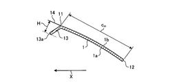
- a radial direction and the circumferential direction of a circle around the rotation axis, the radius of the outer periphery of the blade and r 1, a blade center radius r ma when the inner circumference of the radius of the blade was set to r 2 r ma ( r 1 + r 2 ) / 2, and the blade length along the circumferential direction at the blade center radius r ma is the chord length cm, and the tangent to the leading edge when viewed along the radial direction in perpendicular direction extending pressure side for a distance between the tip and the tangent of the protrusion protrusion amount H satisfies the relationship of 0 ⁇ H ⁇ 0.03 ⁇ c m .
- the propeller fan according to the present invention has an effect of more reliably suppressing noise.
- FIG. 1 is a diagram illustrating a propeller fan according to a first embodiment of the present invention.
- the propeller fan 10 includes a boss portion 2 and a blade 1.
- the boss portion 2 receives a driving force from a driving source (not shown) and rotates around the rotation shaft 3.
- the drive source is, for example, a motor.
- the blade 1 is provided around the boss portion 2 and rotates together with the boss portion 2.
- the rotation direction of the boss part 2 and the blade 1 is indicated by an arrow X.
- the radial direction of a circle around the rotation shaft 3 is simply referred to as the radial direction.
- the circumferential direction of the circle centering on the rotating shaft 3 is simply referred to as the circumferential direction.
- FIG. 2 is a cross-sectional view of the blade cut along the line II-II shown in FIG.
- a line II-II is an arc having a blade center radius rma around the rotation axis 3.
- the cross-sectional view shown in FIG. 2 can be rephrased as a cross-sectional view of the blade 1 viewed along the radial direction.
- the blade 1 is provided with an inclination with respect to the rotation direction, and has a positive pressure surface 1a that is a surface facing forward in the rotation direction and a negative pressure surface 1b that is a surface facing rearward in the rotation direction. From the front edge part 11 which is the front edge in the rotation direction of the blade 1, a protruding part 13 protruding toward the positive pressure surface 1a is provided. The rear edge in the rotation direction of the blade 1 becomes the rear edge portion 12.
- FIG. 3 is a view showing the flow field of the airflow when the blade rotates with respect to the cross-sectional view shown in FIG.
- the airflow that flows into the front edge portion 11 of the blade 1 may cause separation of the airflow on the negative pressure surface 1 b side of the front edge portion 11.
- it is effective to suppress a separation region where separation occurs. That is, if the noise is suppressed, it can be considered that the separation region is suppressed.
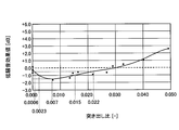
- FIG. 4 is a diagram showing the relationship between the protrusion ratio ⁇ H and the low noise effect value.
- shaft shown in FIG. 4 has shown the low noise effect value which is a difference with the noise when the protrusion part 13 is not provided.
- the low noise effect value is positive when the noise is larger than the noise when the protruding portion 13 is not provided, and is low when the noise is lower than the noise when the protruding portion 13 is not provided.
- the effect value is negative.
- the horizontal axis shown in FIG. 4 indicates the protrusion ratio ⁇ H.
- the point which plotted the result of having measured the low noise effect value by changing protrusion ratio (DELTA) H was tied and shown by the approximate curve.
- the projecting amount H ⁇ H ⁇ c m of the protruding portion 13, 0 ⁇ the provision within the H ⁇ 0.03 ⁇ c m, as compared with the case where the protrusion 13 is not provided It can be seen that noise is suppressed.
- a low noise effect of 0.5 dB or more is obtained within a range of 0.0006 ⁇ cm ⁇ H ⁇ 0.022 ⁇ cm, and a range of 0.0023 ⁇ cm ⁇ H ⁇ 0.015 ⁇ cm .
- a low noise effect of 1.0 dB or more can be obtained.
- section modulus of the blade 1 is increased by providing the protruding portion 13 at the front edge portion 11 of the blade 1, the stress generated at the root portion of the blade 1 during the rotation of the propeller fan 10 is reduced. That is, the strength of the blade 1 is improved.
- the configuration described in the above embodiment shows an example of the content of the present invention, and can be combined with another known technique, and can be combined with other configurations within the scope of the present invention. It is also possible to omit or change the part.
Landscapes
- Engineering & Computer Science (AREA)
- Mechanical Engineering (AREA)
- General Engineering & Computer Science (AREA)
- Structures Of Non-Positive Displacement Pumps (AREA)
Abstract
L'invention concerne un ventilateur à hélice ayant une partie bossage qui tourne autour d'un axe de rotation, une lame qui est disposée autour de la partie de bossage et tourne conjointement avec la partie de bossage et qui a une surface de pression positive faisant face vers l'avant dans la direction de rotation et une surface de pression négative faisant face vers l'arrière dans la direction de rotation, et une saillie qui fait saillie à partir du bord avant, qui est un bord avant dans la direction de rotation de la lame, vers le côté de surface de pression positive. Lorsque la direction radiale et la direction circonférentielle du cercle centré sur l'axe de rotation sont définies, le rayon de la circonférence extérieure de la lame est désigné par r1, le rayon de la circonférence interne de la lame est désigné par r2, le rayon de centre d'aube rma est pris comme rma = (r1 + r2)/2, et la longueur de lame le long de la direction circonférentielle au niveau du rayon central d'aube rma est prise en tant que longueur de corde cm, la quantité de saillie H, qui est la distance entre la pointe de la saillie et la tangente, dans la direction perpendiculaire s'étendant vers la surface de pression positive par rapport à la tangente du bord avant, vu le long de la direction radiale, satisfait la relation suivante: 0 < H ≤ 0,03 × cm.
Priority Applications (2)
| Application Number | Priority Date | Filing Date | Title |
|---|---|---|---|
| PCT/JP2018/015744 WO2019202641A1 (fr) | 2018-04-16 | 2018-04-16 | Ventilateur à hélice |
| TW107128442A TWI661133B (zh) | 2018-04-16 | 2018-08-15 | 螺旋槳式風扇 |
Applications Claiming Priority (1)
| Application Number | Priority Date | Filing Date | Title |
|---|---|---|---|
| PCT/JP2018/015744 WO2019202641A1 (fr) | 2018-04-16 | 2018-04-16 | Ventilateur à hélice |
Publications (1)
| Publication Number | Publication Date |
|---|---|
| WO2019202641A1 true WO2019202641A1 (fr) | 2019-10-24 |
Family
ID=67764330
Family Applications (1)
| Application Number | Title | Priority Date | Filing Date |
|---|---|---|---|
| PCT/JP2018/015744 Ceased WO2019202641A1 (fr) | 2018-04-16 | 2018-04-16 | Ventilateur à hélice |
Country Status (2)
| Country | Link |
|---|---|
| TW (1) | TWI661133B (fr) |
| WO (1) | WO2019202641A1 (fr) |
Citations (6)
| Publication number | Priority date | Publication date | Assignee | Title |
|---|---|---|---|---|
| US1815529A (en) * | 1929-02-08 | 1931-07-21 | Herman Nelson Corp | Fan construction |
| US4684324A (en) * | 1985-08-02 | 1987-08-04 | Gate S.P.A. | Axial fan, particularly for motor vehicles |
| JPH05502637A (ja) * | 1989-06-30 | 1993-05-13 | エアフロー リサーチ アンド マニュファクチュアリング コーポレーション | 軽量羽根 |
| JPH08177792A (ja) * | 1994-10-25 | 1996-07-12 | Matsushita Seiko Co Ltd | 軸流ファン |
| JPH10510021A (ja) * | 1994-11-18 | 1998-09-29 | アイティーティー・オートモーティブ・エレクトリカル・システムズ・インコーポレーテッド | 球根状先端縁を有した高揚力翼形と湾曲した平面形状とを伴った冷却ファン翼 |
| US20160102674A1 (en) * | 2014-10-10 | 2016-04-14 | Trane International Inc. | Fan Blade |
Family Cites Families (4)
| Publication number | Priority date | Publication date | Assignee | Title |
|---|---|---|---|---|
| AU2003207098B2 (en) * | 2002-02-28 | 2004-12-23 | Daikin Industries, Ltd. | Fan |
| CN201050500Y (zh) * | 2007-04-09 | 2008-04-23 | 苏跃忠 | 一种吊扇风叶 |
| CN201382021Y (zh) * | 2009-03-25 | 2010-01-13 | 广东美的电器股份有限公司 | 一种轴流风轮 |
| CN206582170U (zh) * | 2017-01-22 | 2017-10-24 | 佛山市顺德区新双岭机电科技有限公司 | 一种新型的电风扇扇叶 |
-
2018
- 2018-04-16 WO PCT/JP2018/015744 patent/WO2019202641A1/fr not_active Ceased
- 2018-08-15 TW TW107128442A patent/TWI661133B/zh not_active IP Right Cessation
Patent Citations (6)
| Publication number | Priority date | Publication date | Assignee | Title |
|---|---|---|---|---|
| US1815529A (en) * | 1929-02-08 | 1931-07-21 | Herman Nelson Corp | Fan construction |
| US4684324A (en) * | 1985-08-02 | 1987-08-04 | Gate S.P.A. | Axial fan, particularly for motor vehicles |
| JPH05502637A (ja) * | 1989-06-30 | 1993-05-13 | エアフロー リサーチ アンド マニュファクチュアリング コーポレーション | 軽量羽根 |
| JPH08177792A (ja) * | 1994-10-25 | 1996-07-12 | Matsushita Seiko Co Ltd | 軸流ファン |
| JPH10510021A (ja) * | 1994-11-18 | 1998-09-29 | アイティーティー・オートモーティブ・エレクトリカル・システムズ・インコーポレーテッド | 球根状先端縁を有した高揚力翼形と湾曲した平面形状とを伴った冷却ファン翼 |
| US20160102674A1 (en) * | 2014-10-10 | 2016-04-14 | Trane International Inc. | Fan Blade |
Also Published As
| Publication number | Publication date |
|---|---|
| TWI661133B (zh) | 2019-06-01 |
| TW201943968A (zh) | 2019-11-16 |
Similar Documents
| Publication | Publication Date | Title |
|---|---|---|
| CN111133201B (zh) | 螺旋桨式风扇以及轴流式鼓风机 | |
| CN110573746B (zh) | 螺旋桨式风扇 | |
| KR101251130B1 (ko) | 프로펠러 팬 | |
| JP4048302B2 (ja) | 軸流ファン | |
| WO2019150567A1 (fr) | Ventilateur à écoulement axial | |
| JP2016102467A (ja) | 送風装置 | |
| KR20070122376A (ko) | 축류 송풍기 | |
| CN118715376A (zh) | 叶轮、送风机及空气调节机 | |
| WO2022070500A1 (fr) | Ventilateur à hélice | |
| JP6971960B2 (ja) | プロペラファン | |
| WO2019202641A1 (fr) | Ventilateur à hélice | |
| JP2005155579A (ja) | 多翼送風ファン | |
| JP2730344B2 (ja) | 送風機の羽根車 | |
| KR20170102097A (ko) | 누류 및 와류 억제용 축류팬 | |
| JP7069406B2 (ja) | プロペラファンおよび送風装置 | |
| JP4747784B2 (ja) | 軸流送風機の羽根車 | |
| KR100852950B1 (ko) | 축류팬의 블레이드 구조 | |
| KR100487375B1 (ko) | 축류팬 | |
| KR100504480B1 (ko) | 축류팬 | |
| KR100487338B1 (ko) | 축류팬 | |
| KR100487334B1 (ko) | 축류팬 장치 | |
| JP2022075846A (ja) | 翼車および軸流送風機 | |
| JP2005201203A (ja) | 多翼ファン | |
| WO2023079697A1 (fr) | Ventilateur à hélice, soufflante et climatiseur | |
| JP2006037929A (ja) | 空調用送風機羽根車 |
Legal Events
| Date | Code | Title | Description |
|---|---|---|---|
| 121 | Ep: the epo has been informed by wipo that ep was designated in this application |
Ref document number: 18915337 Country of ref document: EP Kind code of ref document: A1 |
|
| NENP | Non-entry into the national phase |
Ref country code: DE |
|
| 122 | Ep: pct application non-entry in european phase |
Ref document number: 18915337 Country of ref document: EP Kind code of ref document: A1 |
|
| NENP | Non-entry into the national phase |
Ref country code: JP |