WO2019202731A1 - Système d'échange de chaleur de véhicule et système de climatisation de véhicule - Google Patents
Système d'échange de chaleur de véhicule et système de climatisation de véhicule Download PDFInfo
- Publication number
- WO2019202731A1 WO2019202731A1 PCT/JP2018/016284 JP2018016284W WO2019202731A1 WO 2019202731 A1 WO2019202731 A1 WO 2019202731A1 JP 2018016284 W JP2018016284 W JP 2018016284W WO 2019202731 A1 WO2019202731 A1 WO 2019202731A1
- Authority
- WO
- WIPO (PCT)
- Prior art keywords
- vehicle
- air
- heat exchanger
- heat exchange
- temperature
- Prior art date
- Legal status (The legal status is an assumption and is not a legal conclusion. Google has not performed a legal analysis and makes no representation as to the accuracy of the status listed.)
- Ceased
Links
Images

Classifications
-
- F—MECHANICAL ENGINEERING; LIGHTING; HEATING; WEAPONS; BLASTING
- F24—HEATING; RANGES; VENTILATING
- F24F—AIR-CONDITIONING; AIR-HUMIDIFICATION; VENTILATION; USE OF AIR CURRENTS FOR SCREENING
- F24F12/00—Use of energy recovery systems in air conditioning, ventilation or screening
- F24F12/001—Use of energy recovery systems in air conditioning, ventilation or screening with heat-exchange between supplied and exhausted air
- F24F12/006—Use of energy recovery systems in air conditioning, ventilation or screening with heat-exchange between supplied and exhausted air using an air-to-air heat exchanger
-
- B—PERFORMING OPERATIONS; TRANSPORTING
- B60—VEHICLES IN GENERAL
- B60H—ARRANGEMENTS OF HEATING, COOLING, VENTILATING OR OTHER AIR-TREATING DEVICES SPECIALLY ADAPTED FOR PASSENGER OR GOODS SPACES OF VEHICLES
- B60H1/00—Heating, cooling or ventilating devices
- B60H1/00007—Combined heating, ventilating, or cooling devices
- B60H1/00021—Air flow details of HVAC devices
- B60H1/00035—Air flow details of HVAC devices for sending an air stream of uniform temperature into the passenger compartment
- B60H1/00042—Air flow details of HVAC devices for sending an air stream of uniform temperature into the passenger compartment the air passing only one heat exchanger
-
- B—PERFORMING OPERATIONS; TRANSPORTING
- B60—VEHICLES IN GENERAL
- B60H—ARRANGEMENTS OF HEATING, COOLING, VENTILATING OR OTHER AIR-TREATING DEVICES SPECIALLY ADAPTED FOR PASSENGER OR GOODS SPACES OF VEHICLES
- B60H1/00—Heating, cooling or ventilating devices
- B60H1/00642—Control systems or circuits; Control members or indication devices for heating, cooling or ventilating devices
- B60H1/00735—Control systems or circuits characterised by their input, i.e. by the detection, measurement or calculation of particular conditions, e.g. signal treatment, dynamic models
- B60H1/00785—Control systems or circuits characterised by their input, i.e. by the detection, measurement or calculation of particular conditions, e.g. signal treatment, dynamic models by the detection of humidity or frost
-
- B—PERFORMING OPERATIONS; TRANSPORTING
- B60—VEHICLES IN GENERAL
- B60H—ARRANGEMENTS OF HEATING, COOLING, VENTILATING OR OTHER AIR-TREATING DEVICES SPECIALLY ADAPTED FOR PASSENGER OR GOODS SPACES OF VEHICLES
- B60H1/00—Heating, cooling or ventilating devices
- B60H1/00642—Control systems or circuits; Control members or indication devices for heating, cooling or ventilating devices
- B60H1/00814—Control systems or circuits characterised by their output, for controlling particular components of the heating, cooling or ventilating installation
- B60H1/00878—Control systems or circuits characterised by their output, for controlling particular components of the heating, cooling or ventilating installation the components being temperature regulating devices
- B60H1/00899—Controlling the flow of liquid in a heat pump system
-
- B—PERFORMING OPERATIONS; TRANSPORTING
- B60—VEHICLES IN GENERAL
- B60H—ARRANGEMENTS OF HEATING, COOLING, VENTILATING OR OTHER AIR-TREATING DEVICES SPECIALLY ADAPTED FOR PASSENGER OR GOODS SPACES OF VEHICLES
- B60H1/00—Heating, cooling or ventilating devices
- B60H1/00642—Control systems or circuits; Control members or indication devices for heating, cooling or ventilating devices
- B60H1/00814—Control systems or circuits characterised by their output, for controlling particular components of the heating, cooling or ventilating installation
- B60H1/00878—Control systems or circuits characterised by their output, for controlling particular components of the heating, cooling or ventilating installation the components being temperature regulating devices
- B60H1/00899—Controlling the flow of liquid in a heat pump system
- B60H1/00921—Controlling the flow of liquid in a heat pump system where the flow direction of the refrigerant does not change and there is an extra subcondenser, e.g. in an air duct
-
- B—PERFORMING OPERATIONS; TRANSPORTING
- B60—VEHICLES IN GENERAL
- B60H—ARRANGEMENTS OF HEATING, COOLING, VENTILATING OR OTHER AIR-TREATING DEVICES SPECIALLY ADAPTED FOR PASSENGER OR GOODS SPACES OF VEHICLES
- B60H1/00—Heating, cooling or ventilating devices
- B60H1/02—Heating, cooling or ventilating devices the heat being derived from the propulsion plant
- B60H1/03—Heating, cooling or ventilating devices the heat being derived from the propulsion plant and from a source other than the propulsion plant
- B60H1/039—Heating, cooling or ventilating devices the heat being derived from the propulsion plant and from a source other than the propulsion plant from air leaving the interior of the vehicle, i.e. heat recovery
-
- B—PERFORMING OPERATIONS; TRANSPORTING
- B60—VEHICLES IN GENERAL
- B60H—ARRANGEMENTS OF HEATING, COOLING, VENTILATING OR OTHER AIR-TREATING DEVICES SPECIALLY ADAPTED FOR PASSENGER OR GOODS SPACES OF VEHICLES
- B60H1/00—Heating, cooling or ventilating devices
- B60H1/24—Ventilating devices where the heating or cooling is irrelevant
- B60H1/248—Air-extractors, air-evacuation from the vehicle interior
-
- F—MECHANICAL ENGINEERING; LIGHTING; HEATING; WEAPONS; BLASTING
- F24—HEATING; RANGES; VENTILATING
- F24F—AIR-CONDITIONING; AIR-HUMIDIFICATION; VENTILATION; USE OF AIR CURRENTS FOR SCREENING
- F24F11/00—Control or safety arrangements
- F24F11/30—Control or safety arrangements for purposes related to the operation of the system, e.g. for safety or monitoring
- F24F11/46—Improving electric energy efficiency or saving
-
- B—PERFORMING OPERATIONS; TRANSPORTING
- B60—VEHICLES IN GENERAL
- B60H—ARRANGEMENTS OF HEATING, COOLING, VENTILATING OR OTHER AIR-TREATING DEVICES SPECIALLY ADAPTED FOR PASSENGER OR GOODS SPACES OF VEHICLES
- B60H1/00—Heating, cooling or ventilating devices
- B60H1/00357—Air-conditioning arrangements specially adapted for particular vehicles
- B60H1/00385—Air-conditioning arrangements specially adapted for particular vehicles for vehicles having an electrical drive, e.g. hybrid or fuel cell
- B60H1/00392—Air-conditioning arrangements specially adapted for particular vehicles for vehicles having an electrical drive, e.g. hybrid or fuel cell for electric vehicles having only electric drive means
-
- B—PERFORMING OPERATIONS; TRANSPORTING
- B60—VEHICLES IN GENERAL
- B60H—ARRANGEMENTS OF HEATING, COOLING, VENTILATING OR OTHER AIR-TREATING DEVICES SPECIALLY ADAPTED FOR PASSENGER OR GOODS SPACES OF VEHICLES
- B60H1/00—Heating, cooling or ventilating devices
- B60H1/00007—Combined heating, ventilating, or cooling devices
- B60H1/00021—Air flow details of HVAC devices
- B60H2001/00078—Assembling, manufacturing or layout details
- B60H2001/00085—Assembling, manufacturing or layout details of air intake
-
- B—PERFORMING OPERATIONS; TRANSPORTING
- B60—VEHICLES IN GENERAL
- B60H—ARRANGEMENTS OF HEATING, COOLING, VENTILATING OR OTHER AIR-TREATING DEVICES SPECIALLY ADAPTED FOR PASSENGER OR GOODS SPACES OF VEHICLES
- B60H1/00—Heating, cooling or ventilating devices
- B60H1/00007—Combined heating, ventilating, or cooling devices
- B60H1/00021—Air flow details of HVAC devices
- B60H2001/00114—Heating or cooling details
- B60H2001/00135—Deviding walls for separate air flows
-
- B—PERFORMING OPERATIONS; TRANSPORTING
- B60—VEHICLES IN GENERAL
- B60L—PROPULSION OF ELECTRICALLY-PROPELLED VEHICLES; SUPPLYING ELECTRIC POWER FOR AUXILIARY EQUIPMENT OF ELECTRICALLY-PROPELLED VEHICLES; ELECTRODYNAMIC BRAKE SYSTEMS FOR VEHICLES IN GENERAL; MAGNETIC SUSPENSION OR LEVITATION FOR VEHICLES; MONITORING OPERATING VARIABLES OF ELECTRICALLY-PROPELLED VEHICLES; ELECTRIC SAFETY DEVICES FOR ELECTRICALLY-PROPELLED VEHICLES
- B60L2240/00—Control parameters of input or output; Target parameters
- B60L2240/10—Vehicle control parameters
- B60L2240/36—Temperature of vehicle components or parts
-
- F—MECHANICAL ENGINEERING; LIGHTING; HEATING; WEAPONS; BLASTING
- F24—HEATING; RANGES; VENTILATING
- F24F—AIR-CONDITIONING; AIR-HUMIDIFICATION; VENTILATION; USE OF AIR CURRENTS FOR SCREENING
- F24F2110/00—Control inputs relating to air properties
- F24F2110/10—Temperature
-
- F—MECHANICAL ENGINEERING; LIGHTING; HEATING; WEAPONS; BLASTING
- F24—HEATING; RANGES; VENTILATING
- F24F—AIR-CONDITIONING; AIR-HUMIDIFICATION; VENTILATION; USE OF AIR CURRENTS FOR SCREENING
- F24F2110/00—Control inputs relating to air properties
- F24F2110/10—Temperature
- F24F2110/12—Temperature of the outside air
-
- F—MECHANICAL ENGINEERING; LIGHTING; HEATING; WEAPONS; BLASTING
- F24—HEATING; RANGES; VENTILATING
- F24F—AIR-CONDITIONING; AIR-HUMIDIFICATION; VENTILATION; USE OF AIR CURRENTS FOR SCREENING
- F24F2110/00—Control inputs relating to air properties
- F24F2110/20—Humidity
-
- F—MECHANICAL ENGINEERING; LIGHTING; HEATING; WEAPONS; BLASTING
- F24—HEATING; RANGES; VENTILATING
- F24F—AIR-CONDITIONING; AIR-HUMIDIFICATION; VENTILATION; USE OF AIR CURRENTS FOR SCREENING
- F24F2110/00—Control inputs relating to air properties
- F24F2110/20—Humidity
- F24F2110/22—Humidity of the outside air
-
- F—MECHANICAL ENGINEERING; LIGHTING; HEATING; WEAPONS; BLASTING
- F24—HEATING; RANGES; VENTILATING
- F24F—AIR-CONDITIONING; AIR-HUMIDIFICATION; VENTILATION; USE OF AIR CURRENTS FOR SCREENING
- F24F7/00—Ventilation
- F24F7/007—Ventilation with forced flow
-
- F—MECHANICAL ENGINEERING; LIGHTING; HEATING; WEAPONS; BLASTING
- F25—REFRIGERATION OR COOLING; COMBINED HEATING AND REFRIGERATION SYSTEMS; HEAT PUMP SYSTEMS; MANUFACTURE OR STORAGE OF ICE; LIQUEFACTION SOLIDIFICATION OF GASES
- F25B—REFRIGERATION MACHINES, PLANTS OR SYSTEMS; COMBINED HEATING AND REFRIGERATION SYSTEMS; HEAT PUMP SYSTEMS
- F25B2700/00—Sensing or detecting of parameters; Sensors therefor
- F25B2700/21—Temperatures
- F25B2700/2106—Temperatures of fresh outdoor air
-
- Y—GENERAL TAGGING OF NEW TECHNOLOGICAL DEVELOPMENTS; GENERAL TAGGING OF CROSS-SECTIONAL TECHNOLOGIES SPANNING OVER SEVERAL SECTIONS OF THE IPC; TECHNICAL SUBJECTS COVERED BY FORMER USPC CROSS-REFERENCE ART COLLECTIONS [XRACs] AND DIGESTS
- Y02—TECHNOLOGIES OR APPLICATIONS FOR MITIGATION OR ADAPTATION AGAINST CLIMATE CHANGE
- Y02B—CLIMATE CHANGE MITIGATION TECHNOLOGIES RELATED TO BUILDINGS, e.g. HOUSING, HOUSE APPLIANCES OR RELATED END-USER APPLICATIONS
- Y02B30/00—Energy efficient heating, ventilation or air conditioning [HVAC]
- Y02B30/56—Heat recovery units
Definitions
- the present application relates to a vehicle heat exchange system and a vehicle air conditioning system installed in a vehicle.
- the present invention is particularly effective when applied to an electric vehicle such as a plug-in hybrid vehicle and an electric vehicle. It is about the system.
- the temperature / humidity difference between the air outside the vehicle cabin (simply referred to as “outside air”) sucked into the vehicle cabin and the vehicle interior air discharged outside the vehicle cabin (also simply referred to as “exhaust”).
- exhaust air the air outside the vehicle cabin
- exhaust air the vehicle interior air discharged outside the vehicle cabin
- the energy that can be recovered by the temperature / humidity exchange function of the temperature / humidity exchanger in the vehicle interior from the discharged “exhaust” to the inhaled “outside air” discharges the “exhaust”. Since it is larger than the energy consumed by the blower and the blower that sucks the “outside air”, it contributes to the improvement of power consumption.
- the present application discloses a technique made in view of the above-described circumstances, and is based on a temperature / humidity difference or a temperature difference between the air outside the vehicle compartment that is sucked into the vehicle interior and the air inside the vehicle compartment that is discharged outside the vehicle interior.
- the purpose is to prevent or suppress the deterioration of power consumption due to this.
- the vehicle heat exchange system disclosed in the present application is: A heat exchanger that exchanges heat between the air in the passenger compartment and the air outside the passenger compartment, A suction blower for sucking air outside the vehicle compartment into the heat exchanger and feeding the heat exchanger to the heat exchanger; A discharge blower for discharging the air outside the vehicle compartment and the air outside the vehicle compartment supplied by the suction blower to the outside of the vehicle compartment after heat exchange with the heat exchanger; and the heat exchanger
- the energy recovered by the heat exchange and the energy consumed by the suction fan and the discharge fan are calculated, and the energy recovered by the heat exchange and consumed by the suction fan and the discharge fan
- a calculation unit that determines which energy is greater than the energy to be performed, and the calculation unit determines that the energy consumed by the suction fan and the discharge fan is greater than the energy recovered by the heat exchange
- a control unit that controls at least one of the suction blower and the discharge blower so that the consumed energy is reduced.
- a control device having The vehicle air conditioning system disclosed in the present application is A heat exchanger that exchanges heat between the air in the passenger compartment and the air outside the passenger compartment, A suction blower for sucking air outside the vehicle compartment into the heat exchanger and feeding the heat exchanger to the heat exchanger; A discharge blower for discharging the air outside the vehicle compartment and the air outside the vehicle compartment supplied by the suction blower to the outside of the vehicle compartment after heat exchange with the heat exchanger; and the heat exchanger
- the energy recovered by the heat exchange and the energy consumed by the suction fan and the discharge fan are calculated, and the energy recovered by the heat exchange and consumed by the suction fan and the discharge fan
- a calculation unit that determines which energy is greater than the energy to be performed, and the calculation unit determines that the energy consumed by the suction fan and the discharge fan is greater than the energy recovered by the heat exchange
- a control unit that controls at least one of the suction blower and the discharge blower so that the consumed energy is reduced.
- the energy recovered by heat exchange in the heat exchanger and the energy consumed by the suction fan and the discharge fan are calculated and recovered by the heat exchange.
- a calculation unit that determines which energy is greater, the energy consumed by the suction blower and the discharge blower, and the suction blower and the discharge blower than the energy recovered by the heat exchange.
- a controller that controls at least one of the suction blower and the discharge blower so that the consumed energy is small when the calculation unit determines that the consumed energy is large. Due to the temperature / humidity difference or temperature difference between the air outside the passenger compartment and the air discharged outside the passenger compartment. Costs can be prevented or suppressed from being deteriorated.
- the energy recovered by heat exchange by the heat exchanger and the energy consumed by the suction blower and the discharge blower are calculated and recovered by the heat exchange.
- An arithmetic unit for determining which energy is larger, energy consumed by the suction fan and the discharge fan, and consumption by the suction fan and the discharge fan than energy recovered by the heat exchange When the calculation unit determines that the energy to be consumed is large, the vehicle heat exchange has a control unit that controls at least one of the suction fan and the discharge fan so that the consumed energy is small System and a heat pump system that air-conditions the interior of the vehicle. Due to the temperature and humidity difference or a temperature difference electric power consumption of the room air discharged to the exterior of the air and the cabin can be prevented or suppressed from being deteriorated.
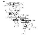
- Embodiment 1 of this application It is a figure which shows Embodiment 1 of this application, and is a figure which shows an example of a system structure at the time of using the heat exchanger of the heat exchange system for vehicles as a total heat exchanger.
- BRIEF DESCRIPTION OF THE DRAWINGS It is a figure which shows Embodiment 1 of this application, and shows an example of a system structure in the case of ventilating from the air blower for suction to the vehicle interior heat exchanger of a heat pump system through the duct which bypasses the heat exchanger of a vehicle heat exchange system.
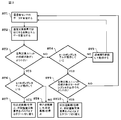
- FIG. It is a figure which shows Embodiment 1 of this application, and is operation
- Embodiment 1 FIG.
- a suction blower 1, a discharge blower 2, a temperature / humidity exchange element 3 (hereinafter referred to as “temperature / humidity exchange element 3”), which is an alias for a total heat exchanger as a heat exchanger, Intake air from outside the vehicle (outside air) 4, Exhaust air from the vehicle interior (circulation) 5, Exhaust air from outside the vehicle (exhaust) 6, Inlet air into the vehicle interior (supply air) 7, Outside heat exchange 8, vehicle interior condenser 9, vehicle interior evaporator 10, compressor 11, refrigerant pipe 12, electronic expansion valves 14 and 15, heating / cooling switching valve 16, first sensor for detecting temperature / humidity or temperature outside the vehicle interior 20.
- a unit 30 ”) and a heat pump system 31 are illustrated. Since the temperature / humidity exchange element 3 is an air resistor, it sucks outside air from the passenger compartment and draws it into the temperature / humidity exchange element 3.
- a discharge blower 2 is required for discharge, and the suction blower 1 and the discharge blower 2 consume electric energy from a battery (not shown) of a vehicle such as an electric vehicle.
- a temperature / humidity sensor 20 for measuring the temperature / humidity of the intake air 4 from outside the vehicle compartment and a temperature / humidity sensor 21 for measuring the temperature / humidity of the discharge air 5 from the vehicle compartment are provided.
- a calculation unit 22 is provided for calculating the total heat energy that can be recovered from the air 5 discharged into the vehicle interior to the air 7 sucked into the vehicle interior by the temperature / humidity exchange element 3, and the suction fan 1 and the discharge fan 2
- the calculation unit 22 of the control device 24 determines the magnitude relationship between the consumed electric energy and the total heat energy that can be recovered, and the operation of the suction fan 1 and the discharge fan 2 is controlled by the control unit 23 of the control device 24 based on the magnitude relationship. It is controlled by.
- the total heat exchange unit 30 that is a heat exchange system includes a suction blower 1, a discharge blower 2, and a temperature / humidity exchange element that is an alias for the total heat exchanger that is a heat exchanger.
- 3 includes a first sensor 20, a second sensor 21, a calculation unit 22, a control unit 23, and a control device 24.
- the heat pump system 31 includes a vehicle exterior heat exchanger 8, a vehicle interior condenser 9, a vehicle interior evaporator 10, a compressor 11, a refrigerant pipe 12, electronic expansion valves 14, 15 and a heating / cooling switching valve 16. ing.
- the vehicle air conditioning system mounted in the vehicle interior includes a total heat exchange unit 30 that exchanges temperature and humidity between the intake air 4 from outside the vehicle interior and the exhaust air 5 from the vehicle interior via the temperature and humidity exchange element 3, And a heat pump system 31 that performs air conditioning using a refrigerant.
- the total heat exchange unit 30 is an inlet (not shown) for introducing the outside air 4 into the passenger compartment, or a blowout outlet (not shown) for the blowout air 6 that blows out the passenger compartment air in the total heat exchange unit 30 to the outside of the passenger compartment.
- the temperature / humidity exchange element 3 is configured, for example, by stacking a spacing plate that separates two layers of air and a holding portion having a spacer function between the spacing plates.
- the vehicle exterior heat exchanger 8 is a refrigerant evaporator that evaporates the refrigerant and absorbs heat
- the vehicle interior condenser 9 is a refrigerant condenser that absorbs heat by condensing the refrigerant and dissipating heat. It has a function to raise the temperature of the air 7.
- the intake air 4 from the outside air dried at a low temperature passes through the temperature / humidity exchanger 3 and intersects with the discharge air 5 from the high-temperature and high-humidity vehicle interior, thereby performing sensible heat exchange and latent heat exchange.
- the intake air 7 from the outside air whose temperature and humidity have increased in the temperature / humidity exchanger 3 is blown to the heat pump system 31, passes through the second heat exchanger 9, and is air-conditioned to a predetermined temperature.
- the first heat exchanger 8 is a refrigerant condenser, which condenses the refrigerant to dissipate heat
- the vehicle interior evaporator 10 is a refrigerant condenser, which absorbs heat by evaporating the refrigerant and absorbing heat. It has a function to lower the temperature of air.
- the intake air 4 from the hot and humid outside air passes through the temperature / humidity exchanger 3 and intersects with the discharge air 5 from the passenger compartment that is dried at low temperature, thereby performing sensible heat exchange and latent heat exchange.
- the intake air 7 from the outside air whose temperature is lowered and humidity is lowered by the temperature / humidity exchanger 3 is blown to the heat pump system 31, passes through the second heat exchanger 9, and is air-conditioned to a predetermined temperature.
- the heating / cooling switching valve 16 adjusts the temperature by adjusting the ratio of the amount of air blown to the vehicle interior condenser or vehicle interior evaporator.
- the calculation unit 22 calculates the total heat energy that can be recovered by the temperature / humidity exchanger 3 from the exhaust air 5 into the vehicle interior to the intake air 7 into the vehicle interior, and is consumed by the suction fan 1 and the discharge fan 2
- the magnitude relationship between the electrical energy to be calculated and the total recoverable heat energy calculated by the calculation unit 22 is determined by the calculation unit 22, and the suction fan 1 and the discharge fan 2 are determined by the magnitude relationship determined by the calculation unit 22.
- the operation is controlled by the control unit 23.
- the total heat energy recovered by the temperature / humidity exchanger 3 includes a temperature / humidity sensor 20 that measures the temperature / humidity of the intake air 4 from the outside of the passenger compartment and a temperature / humidity sensor 21 that measures the temperature / humidity of the discharged air 5 from the passenger compartment.
- the enthalpy is calculated based on the measured values, and the difference is multiplied by the temperature and humidity recovery efficiency of the temperature and humidity exchanger 3.
- the temperature / humidity recovery efficiency ⁇ of the temperature / humidity exchanger 3 is the temperature / humidity exchange efficiency from the air 5 exhausted from the passenger compartment to the intake air 4 from outside the passenger compartment.
- the definition formula is calculated by the following formula (1) Is done.
- the temperature / humidity exchange efficiency of the temperature / humidity exchanger 3 is a value determined by the structure of the temperature / humidity exchanger 3, and the storage unit of the calculation unit 22 stores the value.
- ⁇ (h2-h1) / (h3-h1) (1)
- h1 Enthalpy of the intake air (outside air) 4 from outside the vehicle compartment
- h2 Enthalpy of exhaust air (supply air) 5 into the vehicle interior
- h3 Exhaust air from the vehicle interior (return air) ) Enthalpy of 5.
- the coefficient of performance COP of the total heat exchange unit 30 is defined by the following equation (2).
- V air volume
- h1 enthalpy of intake air (outside air) 4 from outside the vehicle compartment
- h3 enthalpy of exhaust air (circulation) 5 from the vehicle interior
- ⁇ temperature and humidity recovery efficiency
- Q Total electric energy consumed by fans 1 and 2.
- the suction fan 1 and discharge fan 2 are stopped, or only the discharge fan 2 is stopped, and the temperature and humidity exchanger Bypass 3
- the coefficient of performance is higher than 1
- the coefficient of performance is smaller than the coefficient of performance of the heat pump system 31 composed of the refrigerant circuit, it is more energy efficient to adjust the temperature with the heat pump system 31 than to the temperature adjustment with the total heat exchange unit. Therefore, the suction blower 1 and the discharge blower 2 of the total heat exchange unit 30 are stopped, or the discharge blower 2 is stopped as shown in FIG. 2, and the temperature and humidity exchanger 3 is bypassed and the suction blower 1 is used as a heat pump.
- Air is sent to the system 31 to adjust the temperature.
- the coefficient of performance of the heat pump system 31 is a value obtained by dividing the heating / cooling capacity of the vehicle interior condenser or vehicle interior evaporator by the total power consumption of the compressor 11 and the suction blower 1.
- the air discharged from the temperature / humidity exchanger 3 may reach the dew point, and the temperature / humidity exchanger 3 may freeze. If the control device 24 determines that the discharged air reaches the dew point based on the detection values of the temperature and humidity sensors 20 and 21 installed outside the vehicle interior, the suction blower 1 for suction air is stopped. By doing so, it becomes possible to control the temperature of the discharged air to be equal to or higher than the dew point, and it is possible to suppress icing of the temperature and humidity exchanger.
- It has a means to calculate the coefficient of performance of the total heat exchange unit, and when the coefficient of performance is low, it has a means to stop the discharge fan 2 or bypass the temperature / humidity exchange element 3, thereby reducing the power consumption of the electric vehicle. Can be suppressed. By controlling the discharge air so as not to reach the dew point, it is possible to suppress icing of the temperature / humidity exchange element 3.
- step ST1 when the control device 24 detects the detection data of the first sensor 20 for detecting the temperature and humidity outside the vehicle interior and the second sensor 21 for detecting the temperature and humidity inside the vehicle interior, the calculation unit 22 calculates the total heat energy that can be recovered by the temperature / humidity exchange element 3.
- step ST3 the control device 24 determines whether the coefficient of performance of the total heat exchange unit 30 calculated by the calculation unit 22 is smaller than 1, and the control device 24 calculates the total heat exchange calculated by the calculation unit 22.
- step ST4 determines whether the heat pump system 31 is operating, and when the control device 24 determines that the heat pump system 31 is not operating, Next, in step ST5, the control device 24 continuously operates the suction fan 1 and the discharge fan 2.
- step ST3 when the control device 24 determines that the coefficient of performance of the total heat exchange unit 30 calculated by the calculation unit 22 is smaller than 1,
- step ST6 the control device 24 determines whether the heat pump system 31 is operating, and when the control device 24 determines that the heat pump system 31 is operating, Next, in step ST7, the control device 24 stops the discharge fan 2 and switches to the duct 25 that bypasses the temperature / humidity exchange element 3.
- step ST6 when the control device 24 determines that the heat pump system 31 is not operating, Next, in step ST8, the control device 24 stops the suction fan 1 and the discharge fan 2.
- step ST4 when the control device 24 determines that the heat pump system 31 is operating, Next, in step ST9, the control device 24 determines whether the coefficient of performance of the total heat exchange unit 30 is smaller than that of the heat pump system 31 (coefficient of performance), and the coefficient of performance of the total heat exchange unit 30 is that of the heat pump system 31.
- step ST10 the control device 24 stops the discharge fan 2 and switches to the duct 25 that bypasses the temperature / humidity exchange element 3. As a result of this switching, air is blown from the suction blower 1 to the vehicle interior evaporator 10 of the heat pump system 31.
- the total heat exchange unit 30 in the present embodiment is exemplified for the case of a total heat exchange unit that is a temperature and humidity heat exchange device that performs heat exchange between sensible heat and latent heat using the temperature and humidity exchange element 3.
- a sensible heat exchange unit having a sensible heat exchanger capable of recovering only sensible heat also has a corresponding effect.
- a sensible heat exchange unit that is a sensible heat exchanger instead of the temperature / humidity exchange element 3 will be described as a second embodiment.
- the system configuration of the vehicle heat exchange system is the same for the total heat exchange unit and the sensible heat exchange unit. Accordingly, the system configuration diagram is also shown in FIGS. 1 and 2 in the case of the second embodiment.
- the temperature / humidity sensor in the operation flow of FIG. 3 is the sensible heat sensor, the temperature / humidity exchange element is the sensible heat exchanger, and the total heat exchange unit is revealed. What is necessary is just to read as a heat exchange unit, respectively.
- the sensible heat exchange unit has a sensible heat exchanger that exchanges sensible heat, and the sensible heat exchanger exchanges sensible heat of discharged air and sensible heat of suction air.
- the temperature exchanger and sensible heat sensor for exchanging sensible heat in the sensible heat exchange unit are less expensive than the temperature and humidity exchanger and temperature and humidity sensor for exchanging total heat in the total heat exchange unit.
- It has a calculation unit 22 that calculates the sensible heat energy that can be recovered from the discharge air 5 into the passenger compartment to the intake air 7 into the passenger compartment by the temperature exchanger 3, and is consumed by the suction fan 1 and the discharge fan 2.
- the operations of the suction fan 1 and the discharge fan 2 are controlled by the magnitude relationship between the electric energy and the sensible heat energy that can be recovered.
- the suction fan 1 and the discharge fan 2 If the sum of the electrical energy consumed by the suction fan 1 and the discharge fan 2 is larger than the sensible heat exchange energy that can be recovered by the temperature exchanger 3, stop the suction fan 1 and the discharge fan 2, or Only the discharge blower 2 is stopped, and air is blown from the suction blower 1 to the vehicle interior evaporator 10 that is the vehicle interior heat exchanger of the heat pump system 31 through the duct 25 that bypasses the heat exchanger 3 that is the sensible heat exchanger. To do.
- the sensible heat energy recovered by the temperature exchanger 3 has a temperature sensor 20 that measures the temperature of the intake air 4 from the outside of the passenger compartment, and a temperature sensor 21 that measures the temperature of the discharged air 5 from the passenger compartment.
- the sensible heat is calculated based on these measured values, and the difference is multiplied by the sensible heat recovery efficiency of the temperature exchanger 3.
- the sensible heat recovery efficiency ⁇ is the temperature exchange efficiency from the exhaled air 5 from the vehicle interior to the intake air 4 from the outside of the vehicle interior, and the definition formula is calculated by the equation (3).
- the temperature exchange efficiency is a value determined by the structure of the temperature exchanger, and the calculation unit 22 stores the value.
- T1 temperature of the intake air (outside air) 4 from outside the vehicle compartment
- T2 temperature of the exhaust air (supply air) 5 into the vehicle interior
- T3 air exhausted from the vehicle interior (return air) )
- T1 temperature of the intake air (outside air) 4 from outside the vehicle compartment
- T2 temperature of the exhaust air (supply air) 5 into the vehicle interior
- T3 air exhausted from the vehicle interior (return air) )
- Temperature of 5 The coefficient of performance COP of the sensible heat exchange unit is defined by the following equation (4).
- V air volume
- T3 temperature of the exhaust air (return air) 5 from the passenger compartment
- T1 temperature of the intake air (outside air) 4 from outside the passenger compartment
- ⁇ temperature recovery efficiency
- Q Total electric energy consumed by the blower 1 for suction and the blower 2 for discharge.
- the coefficient of performance is less than 1, the sensible heat that can be recovered for the input electric energy is small, so the suction fan 1 and discharge fan 2 are stopped, or only the discharge fan 2 is stopped and the temperature is changed.
- Bypass vessel 3 Even if the coefficient of performance is higher than 1, if the coefficient of performance is smaller than the coefficient of performance of the heat pump system 31 composed of the refrigerant circuit, the temperature adjustment with the heat pump system 31 saves energy. The blower 1 and the discharge blower 2 are stopped, or the discharge blower 2 is stopped as shown in FIG. 2, and the suction blower 1 bypasses the temperature exchanger 3 and sends air to the heat pump system 31 for temperature adjustment. .
- the coefficient of performance of the heat pump system 31 is a value obtained by dividing the heating capacity or cooling capacity of the vehicle interior condenser or vehicle interior evaporator by the total power consumption of the compressor 11 and the suction blower 1.
Landscapes
- Engineering & Computer Science (AREA)
- Mechanical Engineering (AREA)
- Physics & Mathematics (AREA)
- Thermal Sciences (AREA)
- Chemical & Material Sciences (AREA)
- Combustion & Propulsion (AREA)
- General Engineering & Computer Science (AREA)
- Air-Conditioning For Vehicles (AREA)
Abstract
La présente invention concerne un dispositif de commande (24) comprenant : une unité de calcul (22) qui calcule l'énergie récupérée par un échangeur de chaleur (3) par échange de chaleur et l'énergie consommée par un ventilateur d'admission (1) et un ventilateur de ventilation (2), et détermine si l'énergie récupérée par échange de chaleur ou l'énergie consommée par le ventilateur d'admission (1) et le ventilateur de ventilation (2) est plus importante ; et une unité de commande (23) qui, lorsque l'unité de calcul (22) détermine que l'énergie consommée par le ventilateur d'admission (1) et le ventilateur de ventilation (2) est plus importante que l'énergie récupérée par échange de chaleur, commande le ventilateur d'admission (1) et/ou le ventilateur de ventilation (2) de façon à réduire l'énergie consommée par ce dernier. Par conséquent, il est possible d'empêcher ou de supprimer une dégradation de l'efficacité énergétique provoquée par des différences de température et d'humidité ou des différences de température entre l'air provenant de l'extérieur de l'habitacle du véhicule aspiré dans l'habitacle du véhicule et l'air d'habitacle du véhicule évacué de l'habitacle du véhicule.
Priority Applications (5)
| Application Number | Priority Date | Filing Date | Title |
|---|---|---|---|
| EP18915294.5A EP3782830B1 (fr) | 2018-04-20 | 2018-04-20 | Système d'échange de chaleur de véhicule et système de climatisation de véhicule |
| PCT/JP2018/016284 WO2019202731A1 (fr) | 2018-04-20 | 2018-04-20 | Système d'échange de chaleur de véhicule et système de climatisation de véhicule |
| CN201880092438.3A CN111989233B (zh) | 2018-04-20 | 2018-04-20 | 车辆用空调系统 |
| US16/981,770 US11833884B2 (en) | 2018-04-20 | 2018-04-20 | Heat exchange system for vehicle and air conditioning system for vehicle |
| JP2020514888A JP6995192B2 (ja) | 2018-04-20 | 2018-04-20 | 車両用空調システム |
Applications Claiming Priority (1)
| Application Number | Priority Date | Filing Date | Title |
|---|---|---|---|
| PCT/JP2018/016284 WO2019202731A1 (fr) | 2018-04-20 | 2018-04-20 | Système d'échange de chaleur de véhicule et système de climatisation de véhicule |
Publications (1)
| Publication Number | Publication Date |
|---|---|
| WO2019202731A1 true WO2019202731A1 (fr) | 2019-10-24 |
Family
ID=68239517
Family Applications (1)
| Application Number | Title | Priority Date | Filing Date |
|---|---|---|---|
| PCT/JP2018/016284 Ceased WO2019202731A1 (fr) | 2018-04-20 | 2018-04-20 | Système d'échange de chaleur de véhicule et système de climatisation de véhicule |
Country Status (5)
| Country | Link |
|---|---|
| US (1) | US11833884B2 (fr) |
| EP (1) | EP3782830B1 (fr) |
| JP (1) | JP6995192B2 (fr) |
| CN (1) | CN111989233B (fr) |
| WO (1) | WO2019202731A1 (fr) |
Cited By (1)
| Publication number | Priority date | Publication date | Assignee | Title |
|---|---|---|---|---|
| EP4147892A1 (fr) * | 2021-09-10 | 2023-03-15 | Thermo King Corporation | Échangeur de chaleur de récupération dans un système de climatisation |
Families Citing this family (4)
| Publication number | Priority date | Publication date | Assignee | Title |
|---|---|---|---|---|
| WO2019202731A1 (fr) * | 2018-04-20 | 2019-10-24 | 三菱電機株式会社 | Système d'échange de chaleur de véhicule et système de climatisation de véhicule |
| US11592215B2 (en) | 2018-08-29 | 2023-02-28 | Waterfurnace International, Inc. | Integrated demand water heating using a capacity modulated heat pump with desuperheater |
| CN114459138B (zh) * | 2022-02-25 | 2023-12-12 | 智己汽车科技有限公司 | 带自主发热鼓风机的空调控制方法及设备 |
| CN115930316B (zh) * | 2022-10-31 | 2025-08-26 | 广东美的暖通设备有限公司 | 新风装置的控制方法、存储介质、新风装置 |
Citations (7)
| Publication number | Priority date | Publication date | Assignee | Title |
|---|---|---|---|---|
| JPS5640484B2 (fr) | 1975-05-15 | 1981-09-21 | ||
| JPS62123237A (ja) * | 1985-11-21 | 1987-06-04 | Matsushita Electric Ind Co Ltd | 換気装置の制御方法 |
| JPH07223538A (ja) * | 1994-02-09 | 1995-08-22 | Hitachi Ltd | 車両用換気装置 |
| JP2010076506A (ja) * | 2008-09-24 | 2010-04-08 | Calsonic Kansei Corp | 車両用空気調和装置 |
| JP2012001037A (ja) * | 2010-06-15 | 2012-01-05 | Panasonic Corp | 車両用空調装置 |
| JP2012171522A (ja) * | 2011-02-23 | 2012-09-10 | Panasonic Corp | 車両用空調装置 |
| JP2015028391A (ja) * | 2013-07-30 | 2015-02-12 | パナソニック株式会社 | 空調システム |
Family Cites Families (16)
| Publication number | Priority date | Publication date | Assignee | Title |
|---|---|---|---|---|
| EP0640503B1 (fr) * | 1993-03-22 | 1998-09-23 | Seiko Epson Corporation | Vehicule electrique |
| JP2001272086A (ja) * | 2000-03-29 | 2001-10-05 | Mitsubishi Electric Corp | 空気調和装置、空気調和方法 |
| DE602004006248T2 (de) * | 2003-04-17 | 2007-12-27 | Toyota Jidosha Kabushiki Kaisha, Toyota | Energierückgewinnungsystem |
| EP1989400B2 (fr) * | 2006-02-27 | 2023-06-28 | Highview Enterprises Limited | Procédé de stockage d'énergie et système de stockage d'énergie cryogénique |
| JP5640484B2 (ja) | 2010-06-15 | 2014-12-17 | パナソニック株式会社 | 車両用空調装置 |
| JP2013189043A (ja) * | 2012-03-13 | 2013-09-26 | Panasonic Corp | 車両用空調装置 |
| DE102013003507A1 (de) * | 2013-03-04 | 2014-09-04 | Volkswagen Aktiengesellschaft | Klimaanlage für ein Fahrzeug sowie Verfahren zum Klimatisieren eines Fahrzeugs |
| US9914338B2 (en) * | 2014-03-06 | 2018-03-13 | GM Global Technology Operations LLC | Thermal management system for a vehicle |
| DE112016002278T5 (de) * | 2015-05-19 | 2018-02-15 | Denso Corporation | Klimatisierungsvorrichtung für Fahrzeug |
| DE112016004180T5 (de) * | 2015-09-15 | 2018-06-14 | Denso Corporation | Motorcontroller, Klimatisierungssystem und Programm für einen Klimatisierungs-Controller |
| JP2017058993A (ja) * | 2015-09-17 | 2017-03-23 | 日本電気株式会社 | 冷却装置、制御方法および制御プログラム |
| US10696125B2 (en) * | 2015-10-26 | 2020-06-30 | Denso Corporation | Vehicle air conditioner |
| JP6535613B2 (ja) * | 2016-01-29 | 2019-06-26 | 株式会社デンソー | 車両用空調装置 |
| JP6680626B2 (ja) * | 2016-06-14 | 2020-04-15 | 本田技研工業株式会社 | 車両用空調装置 |
| KR102334606B1 (ko) * | 2017-04-14 | 2021-12-06 | 한온시스템 주식회사 | 차량용 공조장치의 제어 방법 |
| WO2019202731A1 (fr) * | 2018-04-20 | 2019-10-24 | 三菱電機株式会社 | Système d'échange de chaleur de véhicule et système de climatisation de véhicule |
-
2018
- 2018-04-20 WO PCT/JP2018/016284 patent/WO2019202731A1/fr not_active Ceased
- 2018-04-20 CN CN201880092438.3A patent/CN111989233B/zh not_active Expired - Fee Related
- 2018-04-20 EP EP18915294.5A patent/EP3782830B1/fr active Active
- 2018-04-20 JP JP2020514888A patent/JP6995192B2/ja active Active
- 2018-04-20 US US16/981,770 patent/US11833884B2/en active Active
Patent Citations (7)
| Publication number | Priority date | Publication date | Assignee | Title |
|---|---|---|---|---|
| JPS5640484B2 (fr) | 1975-05-15 | 1981-09-21 | ||
| JPS62123237A (ja) * | 1985-11-21 | 1987-06-04 | Matsushita Electric Ind Co Ltd | 換気装置の制御方法 |
| JPH07223538A (ja) * | 1994-02-09 | 1995-08-22 | Hitachi Ltd | 車両用換気装置 |
| JP2010076506A (ja) * | 2008-09-24 | 2010-04-08 | Calsonic Kansei Corp | 車両用空気調和装置 |
| JP2012001037A (ja) * | 2010-06-15 | 2012-01-05 | Panasonic Corp | 車両用空調装置 |
| JP2012171522A (ja) * | 2011-02-23 | 2012-09-10 | Panasonic Corp | 車両用空調装置 |
| JP2015028391A (ja) * | 2013-07-30 | 2015-02-12 | パナソニック株式会社 | 空調システム |
Cited By (2)
| Publication number | Priority date | Publication date | Assignee | Title |
|---|---|---|---|---|
| EP4147892A1 (fr) * | 2021-09-10 | 2023-03-15 | Thermo King Corporation | Échangeur de chaleur de récupération dans un système de climatisation |
| US12157346B2 (en) | 2021-09-10 | 2024-12-03 | Thermo King Llc | Recovery heat exchanger in an environmental control system |
Also Published As
| Publication number | Publication date |
|---|---|
| JPWO2019202731A1 (ja) | 2021-02-12 |
| EP3782830B1 (fr) | 2023-10-04 |
| EP3782830A4 (fr) | 2022-01-12 |
| US11833884B2 (en) | 2023-12-05 |
| EP3782830A1 (fr) | 2021-02-24 |
| CN111989233A (zh) | 2020-11-24 |
| JP6995192B2 (ja) | 2022-01-14 |
| US20210008962A1 (en) | 2021-01-14 |
| CN111989233B (zh) | 2024-04-26 |
Similar Documents
| Publication | Publication Date | Title |
|---|---|---|
| JP5297154B2 (ja) | 車両空調システムおよびその運転制御方法 | |
| CN105246718B (zh) | 车用空调装置 | |
| CN111989233B (zh) | 车辆用空调系统 | |
| JP5098346B2 (ja) | 換気空調装置 | |
| US20190241044A1 (en) | Heat pump cycle apparatus | |
| CN111615464A (zh) | 车用空调装置 | |
| WO2011086683A1 (fr) | Système de climatisation pour véhicule et procédé de commande d'entraînement associé | |
| CN105745099B (zh) | 车辆用空调装置 | |
| JP5640485B2 (ja) | 車両用空調装置 | |
| CN108688434A (zh) | 车辆用空调装置 | |
| WO2015132843A1 (fr) | Climatiseur | |
| JP5113664B2 (ja) | 空調システム | |
| WO2020053929A1 (fr) | Dispositif de climatisation | |
| WO2013005492A1 (fr) | Dispositif de climatisation pour véhicule à pile à combustible | |
| JP6938950B2 (ja) | 空気調和システム | |
| JP6907653B2 (ja) | 空調システム | |
| JP7438342B2 (ja) | 空気調和装置 | |
| KR101303239B1 (ko) | 공기조화기 및 그 제어방법 | |
| JP7013990B2 (ja) | 車両用空調装置 | |
| JP5364733B2 (ja) | 車両用空調装置 | |
| JP5066022B2 (ja) | 冷暖房システム | |
| JP6745895B2 (ja) | 空調システム | |
| JP7381207B2 (ja) | 空調システム | |
| CN100523657C (zh) | 冷冻空调装置 | |
| JP2025095462A (ja) | 空気調和装置 |
Legal Events
| Date | Code | Title | Description |
|---|---|---|---|
| 121 | Ep: the epo has been informed by wipo that ep was designated in this application |
Ref document number: 18915294 Country of ref document: EP Kind code of ref document: A1 |
|
| WWE | Wipo information: entry into national phase |
Ref document number: 2020514888 Country of ref document: JP |
|
| NENP | Non-entry into the national phase |
Ref country code: DE |
|
| WWE | Wipo information: entry into national phase |
Ref document number: 2018915294 Country of ref document: EP |