WO2019202808A1 - Dispositif de commande de mise au point - Google Patents
Dispositif de commande de mise au point Download PDFInfo
- Publication number
- WO2019202808A1 WO2019202808A1 PCT/JP2019/003126 JP2019003126W WO2019202808A1 WO 2019202808 A1 WO2019202808 A1 WO 2019202808A1 JP 2019003126 W JP2019003126 W JP 2019003126W WO 2019202808 A1 WO2019202808 A1 WO 2019202808A1
- Authority
- WO
- WIPO (PCT)
- Prior art keywords
- operation button
- displayed
- button
- condition
- display
- Prior art date
- Legal status (The legal status is an assumption and is not a legal conclusion. Google has not performed a legal analysis and makes no representation as to the accuracy of the status listed.)
- Ceased
Links
Images


Classifications
-
- G—PHYSICS
- G16—INFORMATION AND COMMUNICATION TECHNOLOGY [ICT] SPECIALLY ADAPTED FOR SPECIFIC APPLICATION FIELDS
- G16H—HEALTHCARE INFORMATICS, i.e. INFORMATION AND COMMUNICATION TECHNOLOGY [ICT] SPECIALLY ADAPTED FOR THE HANDLING OR PROCESSING OF MEDICAL OR HEALTHCARE DATA
- G16H40/00—ICT specially adapted for the management or administration of healthcare resources or facilities; ICT specially adapted for the management or operation of medical equipment or devices
- G16H40/60—ICT specially adapted for the management or administration of healthcare resources or facilities; ICT specially adapted for the management or operation of medical equipment or devices for the operation of medical equipment or devices
- G16H40/63—ICT specially adapted for the management or administration of healthcare resources or facilities; ICT specially adapted for the management or operation of medical equipment or devices for the operation of medical equipment or devices for local operation
-
- A—HUMAN NECESSITIES
- A61—MEDICAL OR VETERINARY SCIENCE; HYGIENE
- A61B—DIAGNOSIS; SURGERY; IDENTIFICATION
- A61B34/00—Computer-aided surgery; Manipulators or robots specially adapted for use in surgery
- A61B34/25—User interfaces for surgical systems
-
- A—HUMAN NECESSITIES
- A61—MEDICAL OR VETERINARY SCIENCE; HYGIENE
- A61B—DIAGNOSIS; SURGERY; IDENTIFICATION
- A61B1/00—Instruments for performing medical examinations of the interior of cavities or tubes of the body by visual or photographical inspection, e.g. endoscopes; Illuminating arrangements therefor
-
- A—HUMAN NECESSITIES
- A61—MEDICAL OR VETERINARY SCIENCE; HYGIENE
- A61B—DIAGNOSIS; SURGERY; IDENTIFICATION
- A61B1/00—Instruments for performing medical examinations of the interior of cavities or tubes of the body by visual or photographical inspection, e.g. endoscopes; Illuminating arrangements therefor
- A61B1/04—Instruments for performing medical examinations of the interior of cavities or tubes of the body by visual or photographical inspection, e.g. endoscopes; Illuminating arrangements therefor combined with photographic or television appliances
- A61B1/045—Control thereof
-
- A—HUMAN NECESSITIES
- A61—MEDICAL OR VETERINARY SCIENCE; HYGIENE
- A61B—DIAGNOSIS; SURGERY; IDENTIFICATION
- A61B17/00—Surgical instruments, devices or methods
-
- A—HUMAN NECESSITIES
- A61—MEDICAL OR VETERINARY SCIENCE; HYGIENE
- A61B—DIAGNOSIS; SURGERY; IDENTIFICATION
- A61B18/00—Surgical instruments, devices or methods for transferring non-mechanical forms of energy to or from the body
- A61B18/04—Surgical instruments, devices or methods for transferring non-mechanical forms of energy to or from the body by heating
- A61B18/12—Surgical instruments, devices or methods for transferring non-mechanical forms of energy to or from the body by heating by passing a current through the tissue to be heated, e.g. high-frequency current
-
- A—HUMAN NECESSITIES
- A61—MEDICAL OR VETERINARY SCIENCE; HYGIENE
- A61B—DIAGNOSIS; SURGERY; IDENTIFICATION
- A61B90/00—Instruments, implements or accessories specially adapted for surgery or diagnosis and not covered by any of the groups A61B1/00 - A61B50/00, e.g. for luxation treatment or for protecting wound edges
-
- A—HUMAN NECESSITIES
- A61—MEDICAL OR VETERINARY SCIENCE; HYGIENE
- A61B—DIAGNOSIS; SURGERY; IDENTIFICATION
- A61B90/00—Instruments, implements or accessories specially adapted for surgery or diagnosis and not covered by any of the groups A61B1/00 - A61B50/00, e.g. for luxation treatment or for protecting wound edges
- A61B90/30—Devices for illuminating a surgical field, the devices having an interrelation with other surgical devices or with a surgical procedure
-
- G—PHYSICS
- G06—COMPUTING OR CALCULATING; COUNTING
- G06F—ELECTRIC DIGITAL DATA PROCESSING
- G06F3/00—Input arrangements for transferring data to be processed into a form capable of being handled by the computer; Output arrangements for transferring data from processing unit to output unit, e.g. interface arrangements
- G06F3/01—Input arrangements or combined input and output arrangements for interaction between user and computer
- G06F3/048—Interaction techniques based on graphical user interfaces [GUI]
- G06F3/0484—Interaction techniques based on graphical user interfaces [GUI] for the control of specific functions or operations, e.g. selecting or manipulating an object, an image or a displayed text element, setting a parameter value or selecting a range
- G06F3/04847—Interaction techniques to control parameter settings, e.g. interaction with sliders or dials
-
- G—PHYSICS
- G16—INFORMATION AND COMMUNICATION TECHNOLOGY [ICT] SPECIALLY ADAPTED FOR SPECIFIC APPLICATION FIELDS
- G16H—HEALTHCARE INFORMATICS, i.e. INFORMATION AND COMMUNICATION TECHNOLOGY [ICT] SPECIALLY ADAPTED FOR THE HANDLING OR PROCESSING OF MEDICAL OR HEALTHCARE DATA
- G16H20/00—ICT specially adapted for therapies or health-improving plans, e.g. for handling prescriptions, for steering therapy or for monitoring patient compliance
- G16H20/40—ICT specially adapted for therapies or health-improving plans, e.g. for handling prescriptions, for steering therapy or for monitoring patient compliance relating to mechanical, radiation or invasive therapies, e.g. surgery, laser therapy, dialysis or acupuncture
-
- G—PHYSICS
- G16—INFORMATION AND COMMUNICATION TECHNOLOGY [ICT] SPECIALLY ADAPTED FOR SPECIFIC APPLICATION FIELDS
- G16H—HEALTHCARE INFORMATICS, i.e. INFORMATION AND COMMUNICATION TECHNOLOGY [ICT] SPECIALLY ADAPTED FOR THE HANDLING OR PROCESSING OF MEDICAL OR HEALTHCARE DATA
- G16H40/00—ICT specially adapted for the management or administration of healthcare resources or facilities; ICT specially adapted for the management or operation of medical equipment or devices
- G16H40/60—ICT specially adapted for the management or administration of healthcare resources or facilities; ICT specially adapted for the management or operation of medical equipment or devices for the operation of medical equipment or devices
- G16H40/67—ICT specially adapted for the management or administration of healthcare resources or facilities; ICT specially adapted for the management or operation of medical equipment or devices for the operation of medical equipment or devices for remote operation
-
- A—HUMAN NECESSITIES
- A61—MEDICAL OR VETERINARY SCIENCE; HYGIENE
- A61B—DIAGNOSIS; SURGERY; IDENTIFICATION
- A61B34/00—Computer-aided surgery; Manipulators or robots specially adapted for use in surgery
- A61B34/25—User interfaces for surgical systems
- A61B2034/254—User interfaces for surgical systems being adapted depending on the stage of the surgical procedure
-
- A—HUMAN NECESSITIES
- A61—MEDICAL OR VETERINARY SCIENCE; HYGIENE
- A61B—DIAGNOSIS; SURGERY; IDENTIFICATION
- A61B34/00—Computer-aided surgery; Manipulators or robots specially adapted for use in surgery
- A61B34/25—User interfaces for surgical systems
- A61B2034/256—User interfaces for surgical systems having a database of accessory information, e.g. including context sensitive help or scientific articles
-
- G—PHYSICS
- G16—INFORMATION AND COMMUNICATION TECHNOLOGY [ICT] SPECIALLY ADAPTED FOR SPECIFIC APPLICATION FIELDS
- G16H—HEALTHCARE INFORMATICS, i.e. INFORMATION AND COMMUNICATION TECHNOLOGY [ICT] SPECIALLY ADAPTED FOR THE HANDLING OR PROCESSING OF MEDICAL OR HEALTHCARE DATA
- G16H80/00—ICT specially adapted for facilitating communication between medical practitioners or patients, e.g. for collaborative diagnosis, therapy or health monitoring
Definitions
- Embodiments of the present invention relate to a centralized control device that centrally controls a plurality of medical devices and facility devices in an operation.
- a nurse in the sterilization area of the operating room operates various input devices such as an operation panel connected to the system controller each time various scene changes are made during the operation. Devices are turned on / off and settings are changed.
- peripheral devices are connected to the system controller. For this reason, even a skilled nurse can quickly identify peripheral devices to be operated according to the scene from a number of devices and call the setting screen of the device to the operation panel to perform the necessary operations. It was difficult. For this reason, there is a problem that the peripheral device cannot be operated quickly and the progress of the operation is delayed.
- an object of the present invention is to provide a centralized control device that can quickly operate peripheral devices and suppress a delay in the progress of surgery.
- the centralized control device includes an operation state acquisition unit that acquires operation states of a plurality of controlled devices used for a procedure, and an operation button that sets and inputs an operation for each of the plurality of controlled devices.
- the operation state of the controlled device is compared with the operation state condition of the controlled device registered in the operation button display condition, and the operation button to be displayed on the operation panel is set according to the comparison result
- an operation button display control unit for controlling the arrangement of the set operation buttons on the operation panel.
- the figure explaining an example of the operation screen of an operation panel. The figure explaining an example of the operation screen of an operation panel.
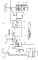
- FIG. 1 is a diagram illustrating an example of an overall configuration of a medical system including a central control device according to an embodiment of the present invention.
- a medical system 1 according to the present embodiment includes a peripheral device 2 that is a controlled device including a plurality of medical devices, an operation panel 4 that receives an operation by an operator such as a nurse, and a display.
- a panel 5 and a system controller 6 that is a centralized control device that centrally controls the peripheral devices 2 and the like are provided.
- the peripheral device 2 is composed of a plurality of medical devices that perform observation, inspection, treatment, and the like. Specifically, the endoscope camera device 7, an insufflation device 8, a light source device 9, an electric scalpel device 10, a monitor (a monitor 11a, a monitor 11b, and a monitor 11c) are configured.
- the peripheral device 2 is not limited to these medical devices, and may include a recording device, for example.
- the operation panel 4 is, for example, a touch panel display in which a liquid crystal display and a touch panel sensor arranged on the liquid crystal display are integrated. This is an operating device for a nurse or the like in a non-sterile area to operate the peripheral device 2, and the operation information is input to the system controller 6.
- the display panel 5 is display means capable of selectively displaying all data during the operation.
- the light source device 9 is connected to an endoscope (not shown) via a light guide cable that transmits illumination light. Illumination light from the light source device 9 is supplied to the endoscope, and illuminates the affected part in the abdomen of the patient into which the insertion part of the endoscope is inserted.
- a camera head equipped with an image sensor is attached to the proximal end side of the insertion portion of the endoscope, and an optical image of the affected area is captured by the image sensor in the camera head.
- An imaging signal imaged by this imaging element is transmitted to the endoscope camera device 7 via a cable.
- the endoscope camera device 7 performs predetermined signal processing on the transmitted imaging signal to generate a video signal. Then, the endoscope camera device 7 outputs the generated video signal to the monitor 11a, the monitor 11b, and the monitor 11c via the system controller 6. On the monitors 11a and 11c suspended from the ceiling and the monitor 11b attached to the wall, an input video signal, that is, an endoscopic image of an affected area or the like is displayed.
- a carbon dioxide gas cylinder (not shown) is connected to the pneumoperitoneum device 8 so that carbon dioxide gas is supplied into the abdomen of the patient through a pneumothorax tube extending from the pneumoperitoneum device 8 to the patient.
- the system controller 6, the endoscope camera device 7, the pneumoperitoneum device 8, the light source device 9, and the electric knife device 10 are installed in a rack 12.
- the system controller 6 includes a patient bed 13 on which a patient lies, an operating light suspended from the ceiling (an operating light 14a and an operating light 14b), an indoor light (not shown), and the like.
- the equipment installed in the operating room is also the peripheral device 2 and is controlled as a controlled device.
- FIG. 1 for example, assuming a surgery using an endoscope and a laparoscope, a set of a system controller 6, an endoscope camera device 7, an insufflation device 8, a light source device 9, and an electric knife device 10 is set. Although two sets are provided, only one set or three or more sets may be used.
- the medical system 1 illustrates the medical system 1 provided in an operating room where endoscopic surgery is performed, the use of the medical system 1 is not limited to endoscopic surgery, and other operations and medical examinations. May be used for Moreover, the medical system 1 may be provided in places other than the operating room such as an examination room.
- the medical system 1 may further include various devices and equipment not shown in FIG. For example, an operative field camera for observing the operative field may be included, and these may be controlled by the system controller 6.
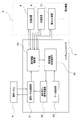
- FIG. 2 is a schematic block diagram illustrating the configuration of the system controller. As shown in FIG. 2, a peripheral device 2 that is a controlled device and an operation panel 4 that is an operation input device are connected to the system controller 6.
- the system controller 6 includes an operation panel control unit 61, an operation button display control unit 62, a data holding unit 63, a peripheral device control unit 64, and a peripheral device state control unit 65.
- the operation panel control unit 61 receives a control signal input by pressing the operation panel 4 such as on / off of a peripheral device and change of a set value.
- the received control signal is output to the peripheral device control unit 64.
- an operation screen 4a for operating peripheral devices is output and displayed on the operation panel 4.
- the peripheral device control unit 64 as an operation state acquisition unit receives various data and setting parameters representing the state of each device from the peripheral device 2 connected to the system controller 6 and capable of centralized control. Are output to the peripheral device state identification unit 65. Further, the control signal for operating the peripheral device 2 input from the operation panel control unit 61 is output to the peripheral device 2 to change the state of the peripheral device 2.
- the peripheral device state identifying unit 65 as the operation button identifying unit compares the state of the peripheral device 2 input from the peripheral device control unit 64 with the operation button display condition, and determines an operation button to be displayed on the operation screen 4a.
- the operation button display condition is set in advance in the data holding unit 63 as a condition registration unit, and is read into the peripheral state identification unit 65 as necessary. Information regarding the determined operation button is output to the operation button display control unit 62.
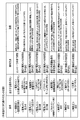
- FIG. 3 and 4 show an example of operation button display conditions.
- FIG. 3 shows an example of a condition for switching the operation button as the operation progresses
- FIG. 4 shows an example of a condition for switching the operation button when an abnormality occurs.
- the operation button display condition includes three conditions: “condition” for switching the operation button, “operation button” to be displayed when the state of the peripheral device matches the condition, and “detection method” for detecting the condition. Become.
- FIG. 3 and 4 also show “effects” obtained by switching the operation buttons according to the respective operation button display conditions.
- the “effect” item is used as a reference when reviewing or changing the table of operation button display conditions, and the content itself does not directly contribute to the operation button switching condition or the switching operation.
- the operation button to be displayed on the operation screen 4a is selected according to the description content of the “operation button” on the second line, and the operation button display control unit 62 is instructed. That is, an instruction is transmitted to the operation button display control unit 62 so that a button for changing the output value of the electric knife device 10 (output value UPDOWN button) is displayed in a shaded manner.
- the operation button to be displayed on the operation screen is selected according to the description content of the “operation button” on the first line, and the operation button display control unit 62 is instructed. That is, an instruction is transmitted to the operation button display control unit 62 so as to display a telephone button for starting communication by telephone with the outside of the operating room.
- the operation button display control unit 62 selects an operation button to be displayed on the operation screen 4a according to the instruction content input from the peripheral device state identification unit 65, and the operation button selected by the operation panel control unit 61 and the display condition of the operation button (Normal display, shaded display, etc.) are output.
- the operation panel control unit 61 generates an operation screen 4 a to be displayed on the operation panel 4 in accordance with the operation button display conditions input from the operation button display control unit 62.
- the generated operation screen 4a is output and displayed on the operation panel 4.
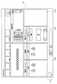
- FIG. 5 is a diagram illustrating an example of the configuration of the operation screen on the operation panel.
- an operation button display area 41 as an operation instruction area for instructing an operation on the peripheral device 2 is arranged on the operation screen 4a.
- the operation screen 4a displays a screen switching button display area 42 in which screen switching buttons for switching the screen to be displayed on the operation panel 4 are arranged, and information on various operations executed so far on the peripheral device 2 and the like.
- An operation log display area 43 for performing operation, a surgery information display area 44 for displaying information on the currently performed operation such as the name of the operation, and the like are also arranged.
- operation button display area 41 operation instruction areas 41a, 41b, 41c, and 41d in which operation buttons for instructing operations on the peripheral device 2 are arranged are arranged. That is, in the example shown in FIG. 5, operation buttons for operating up to four peripheral devices 2 can be arranged on the operation screen 4a.
- operation buttons for operating up to four peripheral devices 2 can be arranged on the operation screen 4a.
- any of the operation buttons set in the “operation button” item of the operation button display condition is selected and arranged.
- the operation buttons related to the video processor which is the endoscope camera device 7 are arranged in the operation instruction area 41 a
- the operation buttons related to the light source device 9 are arranged in the operation instruction area 41 b.
- operation buttons related to the electric knife device 10 are arranged in the operation instruction area 41c
- operation buttons related to the pneumoperitoneum apparatus 8 are arranged in the operation instruction area 41d.
- the number of operation instruction areas 41a, 41b, 41c, 41d arranged on the operation screen 4a is not limited to four, and a necessary number can be arranged.
- the operation buttons need not be displayed in all the operation instruction areas 41a, 41b, 41c, and 41d, and the operation buttons are arranged only according to the instruction of the system controller 6 only for the peripheral device 2 that needs to be operated. For example, when an operation on the peripheral device 2 is unnecessary, all the operation instruction areas 41a, 41b, 41c, and 41d are in a blank state and nothing is displayed.
- the layout of the operation screen 4a is not limited to the layout shown in FIG. 5.
- the operation button display area 41 may not be arranged in the lower half of the screen, and the four operation instruction areas 41a and 41b. 41c, 41d may not be displayed side by side.
- the left half of the operation screen 4a is used as the operation button display area 41, and the area is divided into two parts in the horizontal direction and the vertical direction to create four areas. May be arranged.
- display contents other than the operation button display area 41 on the operation screen 4a are not limited to the screen switching button display area 42, the operation log display area 43, and the surgery information display area 44, and other contents may be displayed. However, there may be areas that are not displayed.
- FIG. 6 is a flowchart for explaining an example of the display control procedure of the operation buttons.
- the peripheral device control unit 64 acquires the state of the various peripheral devices 2 connected (S1). Specifically, according to the method described in “Detection method”, the method or communication path according to each peripheral device 2 can be determined so that the contents set in “condition” of the operation button display condition can be determined. Get the status. For example, output information of the electric scalpel device 10, processing execution information in the endoscope camera device 7, information on the state of lighting / extinguishing of the surgical lights 14 a and 14 b, information on the remaining amount of gas cylinders in the pneumoperitoneum 8 are acquired. The peripheral device control unit 64 outputs the acquired information on the peripheral device 2 to the peripheral device state identification unit 65.
- the peripheral device state identification unit 65 reads the operation button display condition from the data holding unit 63, and compares the acquired state of the peripheral device 2 with the contents set in the “condition” of the display condition (S2). ). When the matching condition is not extracted (S2, No), the process returns to S1 and the state of the peripheral device 2 is acquired.
- the peripheral device state identification unit 65 extracts the contents described in the “operation button” corresponding to the extracted condition (S3). For example, when the operating lights 14a and 14b are turned on, the operating light display condition shown in FIG. Therefore, the contents set in the “operation button” on the seventh line, that is, the monopolar output UPDOWN button of the electric knife device 10 are extracted. Then, the peripheral device state identification unit 65 instructs the extracted operation button to the operation button display control unit 62.
- the operation button display control unit 62 selects the instructed operation button, and sets the selected operation button and operation button display conditions (normal display, shaded display, etc.) in the operation panel control unit 61 ( S4).
- a setting is made to normally display the monopolar output UPDOWN button of the electric knife device 10.
- the operation button display area 41 of the operation screen 4a is set so that newly selected operation buttons are displayed in the order of the operation instruction areas 41a, 41b, 41c, and 41d. That is, when all the operation instruction areas 41a, 41b, 41c, and 41d are in a blank state and no operation buttons are arranged, the operation button newly selected by the operation button display control unit 62 is displayed in the operation instruction area 41a. Set to display. Further, when an operation button is already arranged in the operation instruction area 41a, after the display position of the operation button is moved to the operation instruction area 41b, the newly selected operation button is displayed in the operation instruction area 41a. Set as follows.
- the operation buttons are already arranged in all the operation instruction areas 41a, 41b, 41c, and 41d, the operation buttons arranged in the operation instruction area 41d are deleted, and the operation buttons arranged in the operation instruction area 41c are changed.
- the operation button arranged in the operation instruction area 41b is moved to the operation instruction area 41c, and the operation button arranged in the operation instruction area 41a is moved to the operation instruction area 41b. Then, the newly selected operation button is set to be displayed in the operation instruction area 41a.
- the operation button newly selected is always displayed in the operation instruction area 41a, the operation button that is required to be operated in accordance with the state change of the peripheral device 2 is always displayed at the same position. User convenience is improved, and operation efficiency is improved.
- the operation panel control unit 61 generates an operation screen 4a to be displayed on the operation panel 4 in accordance with the operation button display conditions input from the operation button display control unit 62.
- the generated operation screen 4a is displayed on the operation panel. 4 is output and displayed (S5).
- FIG. 7 to 9 are diagrams illustrating an example of an operation screen on the operation panel.
- the display of the monopolar output UPDOWN button of the electric knife device 10 is set in the state where the operation button is not already arranged in the operation instruction area 41a as in the above example, as shown in FIG.
- the monopolar output UPDOWN button of the electric knife device 10 is displayed in the instruction area 41a, and the three areas of the operation instruction areas 41b, 41c, and 41d are blank.
- the peripheral device state identification unit 65 instructs the extracted operation button to the operation button display control unit 62 (S3).
- the operation button display control unit 62 selects the monopolar output UPDOWN button of the electric knife device 10 (S4). At this time, the monopolar output UPDOWN button of the electric knife device 10 is already displayed in the operation instruction area 41a. Thus, when the same operation button as the operation button displayed immediately before is selected, the operation screen 4a is not updated and the state as it is is continued. That is, the operation panel control unit 61 issues a display instruction to the operation panel 4 without changing the operation screen 4 a displayed on the operation panel 4. (S5).
- the operation button display control unit 62 selects a recording start button of the recording device, and performs a setting to normally display the operation button on the operation panel control unit 61 (S4). At this time, the monopolar output UPDOWN button of the electric knife device 10 is already displayed in the operation instruction area 41a. Therefore, the operation button display control unit 62 moves the display position of the monopolar output UPDOWN button of the electric knife device 10 to the operation instruction area 41b and sets the recording start button of the recording apparatus to be displayed in the operation instruction area 41a.
- the operation panel control unit 61 generates an operation screen 4a to be displayed on the operation panel 4 in accordance with the operation button display conditions input from the operation button display control unit 62.
- the generated operation screen 4a is displayed on the operation panel. 4 is output and displayed (S5). In the above case, the operation screen 4a as shown in FIG.
- the condition of the third row of the operation button display conditions shown in FIG. 3 is matched in S2. Therefore, the contents set in the “operation button” on the third line, that is, the smoke exhaust button of the pneumoperitoneum 8 is extracted. Then, the peripheral device state identification unit 65 instructs the extracted operation button to the operation button display control unit 62 (S3).
- the operation button display control unit 62 selects the smoke exhaust button of the pneumoperitoneum 8, and performs a setting to normally display the operation button on the operation panel control unit 61 (S4). At this time, the recording start button of the recording apparatus is already displayed in the operation instruction area 41a. Further, the monopolar output UPDOWN button of the electric knife device 10 is already displayed in the operation instruction area 41b. Accordingly, the operation button display control unit 62 moves the display position of the monopolar output UPDOWN button of the electric knife device 10 to the operation instruction area 41c and moves the display position of the recording start button of the recording apparatus to the operation instruction area 41b. Then, the operation instruction area 41a is set to display the smoke exhaust button of the pneumoperitoneum 8.
- the operation panel control unit 61 generates an operation screen 4a to be displayed on the operation panel 4 in accordance with the operation button display conditions input from the operation button display control unit 62.
- the generated operation screen 4a is displayed on the operation panel. 4 is output and displayed (S5). In the above case, the operation screen 4a as shown in FIG.
- Buttons are registered in advance as operation button conditions.
- the state of the peripheral device 2 is periodically acquired, and compared with the operation button condition. If the conditions match, the registered operation button is automatically displayed on the operation screen 4a.
- predetermined operation buttons of peripheral devices that need to be controlled are automatically displayed on the operation panel 4 as the procedure progresses or when an abnormality occurs. Therefore, there is no need to search for an operation button and call it on the screen, the peripheral device can be operated quickly, and the delay in the progress of surgery can be suppressed.
Landscapes
- Health & Medical Sciences (AREA)
- Engineering & Computer Science (AREA)
- Life Sciences & Earth Sciences (AREA)
- Surgery (AREA)
- Biomedical Technology (AREA)
- Public Health (AREA)
- General Health & Medical Sciences (AREA)
- Medical Informatics (AREA)
- Nuclear Medicine, Radiotherapy & Molecular Imaging (AREA)
- Animal Behavior & Ethology (AREA)
- Veterinary Medicine (AREA)
- Heart & Thoracic Surgery (AREA)
- Molecular Biology (AREA)
- Physics & Mathematics (AREA)
- Pathology (AREA)
- Human Computer Interaction (AREA)
- Primary Health Care (AREA)
- Epidemiology (AREA)
- General Engineering & Computer Science (AREA)
- Theoretical Computer Science (AREA)
- Business, Economics & Management (AREA)
- General Business, Economics & Management (AREA)
- Robotics (AREA)
- Oral & Maxillofacial Surgery (AREA)
- Biophysics (AREA)
- Optics & Photonics (AREA)
- Radiology & Medical Imaging (AREA)
- General Physics & Mathematics (AREA)
- Otolaryngology (AREA)
- Urology & Nephrology (AREA)
- Plasma & Fusion (AREA)
- Endoscopes (AREA)
- Surgical Instruments (AREA)
Abstract
L'invention concerne un dispositif de commande de mise au point comprenant : une unité de commande de machine périphérique (64) qui acquiert l'état de fonctionnement d'une pluralité de machines périphériques (2) utilisées dans une procédure ; un panneau de fonctionnement (4) affichant des boutons de fonctionnement pour régler et entrer des opérations pour chacune des machines périphériques (2) ; une unité de maintien de données (63) moyennant quoi une combinaison de boutons de fonctionnement, qui doivent être affichés sur le panneau de fonctionnement (4) dans le cas où une machine périphérique (2) a rempli une condition d'état de fonctionnement prédéfinie, est enregistrée en tant que condition d'affichage de bouton de fonctionnement ; une unité de reconnaissance d'état de machine périphérique (65), moyennant quoi l'état de fonctionnement de la machine périphérique (2) et la condition d'état de fonctionnement de la machine périphérique (2) enregistrés dans la condition d'affichage de bouton de fonctionnement sont comparés et les boutons de fonctionnement à afficher sur le panneau de fonctionnement (4) sont réglés selon le résultat de comparaison ; et une unité de commande d'affichage de bouton de fonctionnement (62) commandant le placement, dans le panneau de fonctionnement (4), des boutons de fonctionnement qui ont été réglés.
Priority Applications (1)
| Application Number | Priority Date | Filing Date | Title |
|---|---|---|---|
| US17/072,534 US11127500B2 (en) | 2018-04-19 | 2020-10-16 | Centralized control apparatus and display control method of operation panel |
Applications Claiming Priority (2)
| Application Number | Priority Date | Filing Date | Title |
|---|---|---|---|
| JP2018-080722 | 2018-04-19 | ||
| JP2018080722A JP2021151277A (ja) | 2018-04-19 | 2018-04-19 | 集中制御装置 |
Related Child Applications (1)
| Application Number | Title | Priority Date | Filing Date |
|---|---|---|---|
| US17/072,534 Continuation US11127500B2 (en) | 2018-04-19 | 2020-10-16 | Centralized control apparatus and display control method of operation panel |
Publications (1)
| Publication Number | Publication Date |
|---|---|
| WO2019202808A1 true WO2019202808A1 (fr) | 2019-10-24 |
Family
ID=68240384
Family Applications (1)
| Application Number | Title | Priority Date | Filing Date |
|---|---|---|---|
| PCT/JP2019/003126 Ceased WO2019202808A1 (fr) | 2018-04-19 | 2019-01-30 | Dispositif de commande de mise au point |
Country Status (3)
| Country | Link |
|---|---|
| US (1) | US11127500B2 (fr) |
| JP (1) | JP2021151277A (fr) |
| WO (1) | WO2019202808A1 (fr) |
Families Citing this family (1)
| Publication number | Priority date | Publication date | Assignee | Title |
|---|---|---|---|---|
| JP2024043644A (ja) * | 2022-09-20 | 2024-04-02 | 株式会社大林組 | 給気照明システム |
Citations (4)
| Publication number | Priority date | Publication date | Assignee | Title |
|---|---|---|---|---|
| JP2001029360A (ja) * | 1999-07-23 | 2001-02-06 | Olympus Optical Co Ltd | 医療制御システム |
| JP2001265432A (ja) * | 2000-03-15 | 2001-09-28 | Central Uni Co Ltd | 集中監視方法 |
| JP2006271885A (ja) * | 2005-03-30 | 2006-10-12 | Olympus Medical Systems Corp | システムコントローラ |
| WO2015142933A1 (fr) * | 2014-03-17 | 2015-09-24 | Intuitive Surgical Operations, Inc. | Installation guidée de dispositif médical commandé à distance |
Family Cites Families (3)
| Publication number | Priority date | Publication date | Assignee | Title |
|---|---|---|---|---|
| JP4236436B2 (ja) | 2002-09-19 | 2009-03-11 | オリンパス株式会社 | 内視鏡外科システム |
| US9639506B2 (en) * | 2011-07-07 | 2017-05-02 | Honeywell International Inc. | Interface for home energy manager |
| EP3392750A4 (fr) * | 2015-12-15 | 2018-12-26 | Sony Corporation | Dispositif de traitement d'informations, procédé de traitement d'informations et programme |
-
2018
- 2018-04-19 JP JP2018080722A patent/JP2021151277A/ja active Pending
-
2019
- 2019-01-30 WO PCT/JP2019/003126 patent/WO2019202808A1/fr not_active Ceased
-
2020
- 2020-10-16 US US17/072,534 patent/US11127500B2/en active Active
Patent Citations (4)
| Publication number | Priority date | Publication date | Assignee | Title |
|---|---|---|---|---|
| JP2001029360A (ja) * | 1999-07-23 | 2001-02-06 | Olympus Optical Co Ltd | 医療制御システム |
| JP2001265432A (ja) * | 2000-03-15 | 2001-09-28 | Central Uni Co Ltd | 集中監視方法 |
| JP2006271885A (ja) * | 2005-03-30 | 2006-10-12 | Olympus Medical Systems Corp | システムコントローラ |
| WO2015142933A1 (fr) * | 2014-03-17 | 2015-09-24 | Intuitive Surgical Operations, Inc. | Installation guidée de dispositif médical commandé à distance |
Also Published As
| Publication number | Publication date |
|---|---|
| US11127500B2 (en) | 2021-09-21 |
| JP2021151277A (ja) | 2021-09-30 |
| US20210035684A1 (en) | 2021-02-04 |
Similar Documents
| Publication | Publication Date | Title |
|---|---|---|
| JP5945644B1 (ja) | 医療システム | |
| CN105873539B (zh) | 医疗系统 | |
| US10042978B2 (en) | Medical system | |
| JP2004181229A (ja) | 遠隔手術支援システム及び支援方法 | |
| JP2004267461A (ja) | 内視鏡手術システム | |
| JP2008000282A (ja) | 手技画像記録制御システム及び手術システム | |
| WO2018163644A1 (fr) | Dispositif de traitement d'informations, système d'assistance et procédé de traitement d'informations | |
| JP7188083B2 (ja) | 情報処理装置、情報処理方法および情報処理プログラム | |
| CN110913787B (zh) | 手术支持系统、信息处理方法和信息处理装置 | |
| CN107105994B (zh) | 内窥镜装置 | |
| JP4776937B2 (ja) | 手術システム | |
| JP6374263B2 (ja) | 医療システム | |
| US11127500B2 (en) | Centralized control apparatus and display control method of operation panel | |
| US9782060B2 (en) | Medical system | |
| JP2005245961A (ja) | 画像処理装置 | |
| JP2005111081A (ja) | 内視鏡画像表示処理装置 | |
| JP7451707B2 (ja) | 制御装置、データログの表示方法及び医療用集中制御システム | |
| US20210274103A1 (en) | Video routing in an operating theater | |
| JP2005143918A (ja) | 遠隔手術支援システム | |
| JP2000270318A (ja) | 手術情報表示方法 | |
| JP2005111084A (ja) | 内視鏡システム |
Legal Events
| Date | Code | Title | Description |
|---|---|---|---|
| 121 | Ep: the epo has been informed by wipo that ep was designated in this application |
Ref document number: 19787692 Country of ref document: EP Kind code of ref document: A1 |
|
| NENP | Non-entry into the national phase |
Ref country code: DE |
|
| 122 | Ep: pct application non-entry in european phase |
Ref document number: 19787692 Country of ref document: EP Kind code of ref document: A1 |
|
| NENP | Non-entry into the national phase |
Ref country code: JP |