WO2019203065A1 - Procédé d'irradiation par ultraviolets pour la photophérèse, micro-dispositif pour la photophérèse, et dispositif d'irradiation par ultraviolets pour la photophérèse - Google Patents
Procédé d'irradiation par ultraviolets pour la photophérèse, micro-dispositif pour la photophérèse, et dispositif d'irradiation par ultraviolets pour la photophérèse Download PDFInfo
- Publication number
- WO2019203065A1 WO2019203065A1 PCT/JP2019/015477 JP2019015477W WO2019203065A1 WO 2019203065 A1 WO2019203065 A1 WO 2019203065A1 JP 2019015477 W JP2019015477 W JP 2019015477W WO 2019203065 A1 WO2019203065 A1 WO 2019203065A1
- Authority
- WO
- WIPO (PCT)
- Prior art keywords
- photopheresis
- ultraviolet light
- flow path
- microdevice
- liquid sample
- Prior art date
- Legal status (The legal status is an assumption and is not a legal conclusion. Google has not performed a legal analysis and makes no representation as to the accuracy of the status listed.)
- Ceased
Links
Images


Classifications
-
- A—HUMAN NECESSITIES
- A61—MEDICAL OR VETERINARY SCIENCE; HYGIENE
- A61M—DEVICES FOR INTRODUCING MEDIA INTO, OR ONTO, THE BODY; DEVICES FOR TRANSDUCING BODY MEDIA OR FOR TAKING MEDIA FROM THE BODY; DEVICES FOR PRODUCING OR ENDING SLEEP OR STUPOR
- A61M1/00—Suction or pumping devices for medical purposes; Devices for carrying-off, for treatment of, or for carrying-over, body-liquids; Drainage systems
- A61M1/36—Other treatment of blood in a by-pass of the natural circulatory system, e.g. temperature adaptation, irradiation ; Extra-corporeal blood circuits
Definitions
- the present invention relates to a photopheresis microdevice, an ultraviolet light irradiation apparatus including the microdevice, and an ultraviolet light irradiation method for photopheresis using the ultraviolet light irradiation apparatus.
- the immunity of the human body plays a role in protecting the human body from external enemies (parasites) such as bacteria, viruses, cancer, and parasites, and it can be said that immunity is an indispensable mechanism for human life.
- the immune reaction also causes autoimmune diseases such as skin diseases such as atopic dermatitis and psoriasis, and collagen diseases such as rheumatoid arthritis and systemic lupus erythematosus.
- Autoimmune disease is an immune system that recognizes and eliminates foreign substances that are different from self, such as bacteria, viruses, and tumors. It is a general term for symptoms that develop.
- Photopheresis extractory-derived photochemotherapy
- Photopheresis generally involves adding a photopharmaceutical such as a psoralen derivative to blood taken out of the body, making it absorbed by activated T cells, and then irradiating the blood with ultraviolet light. It is a method of inducing immune tolerance by activating a photopharmaceutical to cause apoptosis or damage of the T cells, thereby suppressing an excessive immune reaction.
- a photopharmaceutical such as a psoralen derivative
- photopheresis In photopheresis, it is not always necessary to add a photosensitive drug, and if the photosensitive drug is added and subjected to ultraviolet light irradiation related to photopheresis, the photosensitive drug is returned to the blood returned to the patient's body. Even if it is contained, since the activated state of the photosensitive drug is not continued once the irradiation with ultraviolet light is completed, side effects may occur in the patient as compared with the immunosuppressive method by administration of an immunosuppressive agent. Is extremely low. For this reason, photopheresis is attracting attention as an immunosuppressive method with fewer side effects than when an immunosuppressive agent is administered. In Europe and the United States, the clinical application of photopheresis for the treatment of autoimmune diseases in which immunosuppressive agents such as steroids are ineffective and the immunosuppression during transplantation treatment such as bone marrow transplantation is rapidly increasing.
- T cells which are a type of white blood cell, as described above.
- blood contains red blood cells in addition to T cells, and hemoglobin contained in red blood cells has a property of exhibiting a large absorbance to ultraviolet light.
- leukocytes are about 3%, whereas red blood cells are about 96%, and more red blood cells are contained than leukocytes.
- the ultraviolet light irradiated by hemoglobin in the red blood cells is absorbed, and as a result, the T cells that are the target to be truly irradiated with ultraviolet light are absorbed.
- Patent Document 1 discloses a photopheresis processing method that can be performed without requiring complicated and high-cost processing such as centrifugation. Specifically, a method has been proposed in which blood is introduced into a fine through-hole formed in a porous body, and in this state, ultraviolet light is irradiated from the outside of the porous body.
- the photopheresis processing method disclosed in Patent Document 1 has the following problems. For example, since a plurality of through holes formed in a porous body are not uniform in the penetrating direction, the irradiation amount of ultraviolet light to each T cell is not uniform, so that the effect of causing apoptosis of the T cell is sufficient. There is a problem that cannot be obtained.
- the diameter of the through-hole formed in the porous body is set to 15 to 50 ⁇ m, for example, in order to make it slightly larger than the diameter of white blood cells (15 ⁇ m). Since it is difficult to make the diameter of the hole uniform with high accuracy, the blood is clogged when introducing blood into the porous body, or even if it does not clog, it takes a long time to introduce blood, There is a problem.
- the present invention has been made based on the circumstances as described above, and its purpose is to provide a liquid sample for photopheresis with high accuracy even though it is not necessary to perform complicated processing such as centrifugation.
- Ultraviolet light irradiation method for photopheresis capable of inducing immune tolerance by causing apoptosis or damage of treated cells contained therein, microdevice used in the ultraviolet light irradiation method, and microdevice It is providing an ultraviolet light irradiation apparatus provided with.
- the method of irradiating ultraviolet light for photopheresis includes a step of introducing a liquid sample for photopheresis into the flow passage in a photopheresis microdevice having a flow passage in a wall, and the flow passage. Irradiating the photopheresis liquid sample introduced into the wall with ultraviolet light through the wall, and The length in the irradiation direction of the ultraviolet light in the flow path is 70 ⁇ m or more and 500 ⁇ m or less.
- the photopheresis liquid sample may be blood.
- the ultraviolet light includes light having a wavelength range of 280 nm to 320 nm.
- the ultraviolet light is irradiated in a direction different from a flow direction of the photopheresis liquid sample in the flow path.
- the photopheresis microdevice of the present invention includes a flow path in a wall portion, a photopheresis liquid sample is introduced into the flow path, and the photopheresis liquid sample introduced into the flow path In contrast, the ultraviolet light is irradiated through the wall,
- the length in the irradiation direction of the ultraviolet light in the flow path is 70 ⁇ m or more and 500 ⁇ m or less.
- the photopheresis liquid sample is blood
- the wall portion preferably transmits ultraviolet light including light having a wavelength range of 280 nm to 320 nm.
- a plurality of the flow paths can be provided independently of each other.
- the micro device for photopheresis according to the present invention is such that a cylindrical rod body having ultraviolet light permeability is provided with a plurality of flow paths made of through holes extending in the longitudinal direction of the rod body independently of each other. It can be.
- the photopheresis microdevice of the present invention includes a first substrate and a second substrate bonded to each other, and the first substrate and the second substrate have the first substrate on the bonding surface of the first substrate and the second substrate.
- a flow path forming portion that becomes a flow path by bonding the substrate and the second substrate is provided, At least one of the first substrate and the second substrate may have ultraviolet light transparency.
- An ultraviolet irradiation apparatus for photopheresis of the present invention the microdevice for photopheresis described above, A light source that transmits ultraviolet light to the flow path through the wall of the photopheresis microdevice from the outside of the photopheresis microdevice.
- the light source may be configured to emit ultraviolet light including light in a wavelength range of 280 nm to 320 nm.
- the light source is disposed so that the ultraviolet light is irradiated in a direction different from a flow direction of the photopheresis liquid sample in the flow path. preferable.
- a liquid sample for photopheresis containing cells to be treated is introduced into a flow path whose length in the ultraviolet light irradiation direction is regulated to 70 ⁇ m or more and 500 ⁇ m or less. Is done.
- the occurrence of clogging of the photopheresis liquid sample in the flow path can be suppressed, so that the photopheresis liquid can be rapidly irradiated with the ultraviolet light to the photopheresis liquid sample.
- the treated cells contained in the sample can be irradiated with ultraviolet light with high uniformity.
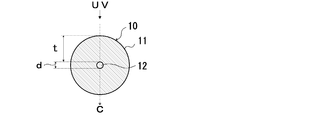
- FIG. 1 is a cross-sectional view along the flow direction of a photopheresis liquid sample, schematically showing a main part in an example of the configuration of the photopheresis ultraviolet light irradiation apparatus of the present invention.
- the ultraviolet light irradiation apparatus for photopheresis of the present invention (hereinafter simply referred to as “ultraviolet light irradiation apparatus”) is used to treat cells to be treated in a series of photopheresis processes performed in photopheresis (extracorporeal circulation photochemotherapy). It is an apparatus for irradiating the contained photopheresis liquid sample with ultraviolet light.
- the ultraviolet light irradiation apparatus is a photopheresis microdevice (hereinafter simply referred to as “microdevice”) including a wall portion 11 having ultraviolet light permeability and a flow passage 12 penetrating the wall portion 11. .) 10 and a light source 20 for irradiating the photopheresis liquid sample S introduced from the outside of the microdevice 10 through the wall 11 of the microdevice 10 into the flow passage 12 with ultraviolet light. Is provided.
- the micro device 10 is a disposable one that can be replaced for each photopheresis process.
- the liquid sample S for photopheresis is a cell-containing liquid containing cells targeted for apoptosis by irradiation with ultraviolet light (hereinafter also referred to as “treated cells”), specifically, blood, Examples include cerebrospinal fluid, lymph fluid, and liquids obtained by diluting these with physiological saline, and particularly blood (whole blood) from which blood components are not separated.
- treated cells include cerebrospinal fluid, lymph fluid, and liquids obtained by diluting these with physiological saline, and particularly blood (whole blood) from which blood components are not separated.
- the cells to be treated are, for example, white blood cells, particularly T cells.
- the microdevice 10 of the present invention includes a wall portion 11 having ultraviolet light permeability and a flow passage 12 extending through the wall portion 11.
- the photopheresis liquid sample S containing cells to be treated is introduced into the flow path 12, and the wall against the photopheresis liquid sample S introduced into the flow path 12 is provided.
- the ultraviolet light from the light source 20 is irradiated through the part 11.
- the microdevice 10 can be formed of a cylindrical thin tube. The inside of this thin tube is the flow passage 12, and the tube wall is the wall portion 11 of the microdevice 10.
- the flow passage 12 has one inlet and one outlet for the photopheresis liquid sample S at both ends, and these inlets and outlets are communicated through a single path.
- the length of the flow path 12 in the irradiation direction of the ultraviolet light from the light source 20 (hereinafter also referred to as “irradiation direction length”) is 70 ⁇ m or more and 500 ⁇ m or less, and 100 ⁇ m.
- the thickness is preferably 300 ⁇ m or less and particularly preferably 200 ⁇ m or more and 300 ⁇ m or less.
- the irradiation direction length of the flow path 12 is 500 ⁇ m or less, the ultraviolet light from the light source 20 can reach the bottom of the irradiation direction of the ultraviolet light in the flow path 12 (lower part in FIGS. 1 and 2).
- the length of the flow path 12 in the irradiation direction of the ultraviolet light is 70 ⁇ m or more, the components of the photopheresis liquid sample S in the flow path 12 regardless of the components contained in the photopheresis liquid sample S.
- the flow of the photopheresis liquid sample S is not hindered, and particularly when the photopheresis liquid sample S is blood, blood cell components of the blood are clogged in the flow path 12. Can be deterred.
- the length in the irradiation direction of the ultraviolet light (irradiation direction length) in the flow path 12 refers to the length along the traveling direction C (vertical direction in FIG. 2) of the ultraviolet light irradiated to the flow path 12.
- the traveling direction C of the ultraviolet light shown in FIG. 2 is the irradiation direction. 2
- the irradiation direction length d of the microdevice 10 is, for example, the flow direction of the photopheresis liquid sample S with respect to the microdevice 10 (the narrow tube constituting the flow path 12).
- the direction (FIG. 1) is perpendicular to the width of the flow path 12, that is, the irradiation direction of ultraviolet light (Y direction in FIG. 1) and the flow direction of the photopheresis liquid sample S (X direction in FIG. 1).
- the width (hereinafter also referred to as “flow passage width”) in the direction perpendicular to the paper surface (Z direction) is, for example, 70 to 500 ⁇ m.
- a region hereinafter also referred to as “light irradiation region”) R in the flow direction of the photopheresis liquid sample S (hereinafter also referred to as “light irradiation region”) R (hereinafter also referred to as “irradiation length”).
- irradiation region in the flow direction of the photopheresis liquid sample S (hereinafter also referred to as “light irradiation region”) R (hereinafter also referred to as “irradiation length”).
- the thickness of the wall 11, that is, the thickness t in the irradiation direction of the ultraviolet light in the wall 11 varies depending on the material constituting the wall 11, particularly the transmittance of the ultraviolet light, but is about 1 to 5 mm, for example. It is preferable.
- the thickness of the wall part 11 is too small, there exists a possibility that the microdevice 10 may become inferior to durability.
- the thickness of the wall portion 11 is excessive, ultraviolet light having an energy amount sufficient to obtain the effect of inducing immune tolerance by causing apoptosis or damage to the treated cells is circulated. There is a possibility that the bottom of the road 12 cannot be reached.
- the narrow tube constituting the microdevice 10 is, for example, glass such as quartz glass, alkali glass, borosilicate glass; silicone resin, cycloolefin resin (cycloolefin polymer (COP), cycloolefin copolymer (COC), etc.), acrylic resin, etc.
- the synthetic resin can be used.
- the light source 20 provided in the ultraviolet light irradiation apparatus of the present invention emits ultraviolet light, and preferably emits ultraviolet light including light having a wavelength range of 280 nm to 320 nm.
- the light in the wavelength region of 280 nm or more and 320 nm or less is light in the middle wavelength ultraviolet region called so-called UVB.
- UVB middle wavelength ultraviolet region
- the cells to be treated are apoptotic or damaged only by irradiating the photopheresis liquid sample S with UVB without using a photosensitizing medicine such as a psoralen derivative. Can induce immune tolerance.
- UVA ultraviolet region
- UVB light having a longer wavelength than UVB
- a photopharmaceutical such as a psoralen derivative added to the photopheresis liquid sample S.
- a light source 20 that emits UVB for example, an LED element, a XeCl excimer discharge lamp, a metal halide lamp, a fluorescent lamp, a mercury lamp, or the like can be used.
- the light source 20 may be provided with an optical filter that blocks light in a wavelength region other than UVB in a wavelength region of 280 nm to 320 nm among light emitted from the LED element and the lamp.
- the light source 20 is irradiated with light having a shape capable of irradiating ultraviolet light over the entire flow path width of the flow path 12 in the microdevice 10 and over an intended length (irradiation length of the light irradiation region R).
- a rod-shaped light source is preferably used as the light source 20 for the microdevice 10 formed of a thin tube having one flow passage 12.
- a planar light source is preferable to use as the light source.
- the light source 20 is preferably arranged so that the ultraviolet light emitted from the light source 20 is irradiated in a direction different from the flow direction of the photopheresis liquid sample S in the flow path 12 of the microdevice 10. Specifically, the irradiation is preferably performed in a direction substantially perpendicular to the flow direction of the photopheresis liquid sample S.
- the ultraviolet light irradiation method for photopheresis is a method of irradiating cells to be treated with ultraviolet light in a series of photopheresis treatments performed in photopheresis (extracorporeal circulation photochemotherapy).
- the step of introducing the photopheresis liquid sample S into the flow passage 12 of the device 10, and the photopheresis liquid sample S introduced into the flow passage 12 passes through the wall 11 and is transmitted from the light source 20 to the ultraviolet light. Irradiating with light.
- the ultraviolet light irradiation method according to the present invention is performed as follows using the ultraviolet light irradiation apparatus as described above.
- the liquid sample S for photopheresis will be described as blood.
- blood collected from a patient is introduced as a photopheresis liquid sample S into the flow path 12 of the microdevice 10 from an inlet at one end of the flow path 12 by, for example, an infusion pump.
- the blood introduced into the flow passage 12 is circulated in one direction (right direction in FIG. 1) through the flow passage 12 at a constant flow rate.
- the ultraviolet light from the light source 20 passes through the wall portion 11 of the microdevice 10 and is irradiated to the blood flowing through the light irradiation region R in the flow path 12.
- the cells to be processed (white blood cells S1) contained in the blood are circulated while being mixed with the red blood cells S2.
- the length of the irradiation direction of ultraviolet light is in the range of 70 to 500 ⁇ m, which is slightly larger than that of leukocytes, so that the white blood cells are aligned in parallel along the longitudinal direction (flow direction) of the flow path 12.
- An easy environment is created. Therefore, a part of the ultraviolet light transmitted through the wall 11 of the microdevice 10 is irradiated to the cell to be processed (white blood cell S1) without being absorbed by the red blood cell S2 in the blood flowing through the flow path 12.
- the treated cells (white blood cells S1) receive ultraviolet light from the light source 20 during the period from the start end to the end of the light irradiation region in the flow path 12.
- the leukocyte S1 is apoptotic or damaged, and immune tolerance is induced.
- the blood irradiated with ultraviolet light then flows through the flow passage 12 and then is discharged from the outlet and returned to the patient's body again.
- the flow velocity of the photopheresis liquid sample S in the flow path 12 is determined based on the type of the photopheresis liquid sample S, the type of the light source 20, the wavelength and irradiation amount of the emitted ultraviolet light, the flow path width and light in the flow path 12. Depending on the length of the irradiation area, etc., it is possible to obtain ultraviolet light (integrated light amount) with an amount of energy sufficient to obtain the effect of inducing apoptosis by damaging treated cells or inducing immune tolerance. Good.
- the photopheresis liquid sample S containing the cells to be treated is introduced into the flow passage 12 in which the length of the ultraviolet light irradiation direction is regulated to 70 ⁇ m or more and 500 ⁇ m or less.
- the occurrence of clogging of the photopheresis liquid sample S in the flow passage 12 can be suppressed, so that the photopheresis liquid sample S can be rapidly irradiated with ultraviolet light, and photo
- the liquid sample S for pheresis contains components other than the cells to be treated together with the cells to be treated and is circulated in the flow path
- the ultraviolet rays are highly uniform in the cells to be treated contained in the liquid sample S for photopheresis. Light can be irradiated. Therefore, the cells to be treated contained in the photopheresis liquid sample S are immunized by apoptosis or damage with high accuracy, even though no photopharmaceutical is used and centrifugation is not required. Tolerance can be induced.
- the time required for complicated processing such as centrifugation of the photopheresis liquid sample S can be greatly reduced, and the burden on the patient can be greatly reduced.
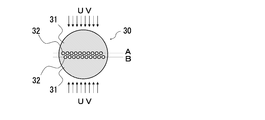
- the micro device may be provided with a plurality of flow paths independently of each other.
- the micro device 30 includes a cylindrical ultraviolet light transmitting rod body 31 having a plurality of flow passages 32 each including a through hole extending in the longitudinal direction of the rod body 31. , And can be provided independently and in parallel.
- a plurality of flow passages 32 are arranged in parallel and at equal intervals on a virtual surface A that is spaced substantially parallel to the surface including the central axis of the rod body 31, and the virtual surface A plurality of flow passages 32 are arranged in parallel and at equal intervals on a virtual plane B that is plane-symmetrical with respect to A and a plane including the central axis of the rod body 31.
- the light source is arranged so that the ultraviolet light from the light source is irradiated to all the flow paths 32 without passing through the other flow paths 32.
- the micro device 30 transmits ultraviolet light through the rod body 31 from the virtual surface A side (upper side in FIG.
- the light source for irradiating with ultraviolet light is preferably a planar light source having a width corresponding to the arrangement width of the flow passage 32.
- the irradiation direction length of all the flow paths 32 is 70 ⁇ m or more and 500 ⁇ m or less.
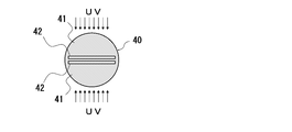
- the micro device 40 has a flow passage 42 formed of a wide slit extending in the longitudinal direction through the rod body 41 in a cylindrical ultraviolet light transmitting rod body 41.
- the surface directions in which the slits extend independently from each other can be provided so as to be parallel to each other.
- two flow passages 42 are arranged symmetrically so as to sandwich a surface including the central axis of the rod body 41.
- the light source is disposed so that the two flow paths 42 are irradiated with ultraviolet light from the light source without passing through the other flow paths 42.
- the rod body 41 is respectively connected from the upper side (upper side in FIG.
- the light source for irradiating the ultraviolet light is preferably a planar light source having a width corresponding to the width of the slit (the width in the left-right direction in FIG. 4) constituting the flow passage 42.
- the irradiation direction lengths of the two flow paths 42 are 70 ⁇ m or more and 500 ⁇ m or less, respectively.
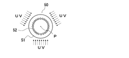
- the microdevice 50 includes a cylindrical rod body having ultraviolet light transparency, and a plurality of flow passages made of through holes extending in the longitudinal direction of the rod body. It can be provided.
- a flow passage 52 including a plurality of holes that penetrate the rod body 51 and extend in the longitudinal direction of the rod body 51 surrounds the central axis P of the rod body 51.
- the flow passages 52 in the rod body 51 are equidistant from the central axis P, and the adjacent flow passages 52 are arranged side by side so as to be equidistant from each other.
- the light sources are arranged so that all the flow paths 52 are irradiated with ultraviolet light from the light sources without passing through the other flow paths 52.
- the micro device 50 is preferably irradiated with ultraviolet light through the rod body 51 from three different directions. Specifically, three light sources (not shown) have their optical axes in the flow direction of the photopheresis liquid sample S in the flow path 52 of the microdevice 50 (direction perpendicular to the paper surface in FIG. 5). They are arranged so as to be substantially vertical and intersect each other in the central axis P at an intersection angle of 120 degrees. In this microdevice 50, it is preferable that the length of the irradiation direction of all the flow paths 52 be 70 ⁇ m or more and 500 ⁇ m or less.
- micro device may be configured by combining a plurality of thin tubes having one flow path.
- the total flow path width can be increased, so that the speed of the photopheresis process can be improved.
- the micro device is not limited to a cylindrical shape such as a thin tube or a rod body, and as shown in FIG. 6, on a small microchip substrate 61A having ultraviolet light transparency such as glass or synthetic resin, It may be composed of a flat microchip 60 in which microchannels are formed by a microfabrication technique.
- the microchip 60 includes a pair of microchip substrates 61A and 61B, and the pair of microchips in a state where a microchannel (a channel forming portion) is formed on the surface of one microchip substrate 61A.
- the substrates 61A and 61B are joined to face each other and the micro flow path is closed, the flow path 62 through which the photopheresis liquid sample S flows is formed.
- one microchip substrate 61A on which microchannels are formed is made of silicone rubber such as polydimethylsiloxane (PDMS), and the other microchip substrate 61B is made of quartz glass.
- PDMS polydimethylsiloxane
- the microchip 60 one or a plurality of flow passages 62 are formed. In FIG. 6, six flow passages 62 are formed.
- the ultraviolet light irradiation apparatus including the microchip 60 the light source is disposed so that all the flow paths 62 are irradiated with ultraviolet light from the light source without passing through the other flow paths 62.
- the microchip 60 is transmitted through the other microchip substrate 61B from the substrate side made of a material having a good ultraviolet light transmission property, that is, from the other microchip substrate 61B side to transmit ultraviolet light. Irradiation is preferred.
- the light source for irradiating the ultraviolet light is preferably a planar light source having a width corresponding to the arrangement width of the flow passage 62. In the microchip 60, it is preferable that the irradiation direction lengths of all the flow paths 62 be 70 ⁇ m or more and 500 ⁇ m or less.
- the ultraviolet irradiation method for photopheresis according to the present invention is performed by using a flow irradiation method, that is, continuously circulating a photopheresis liquid sample in the flow path of the microdevice from the viewpoint of improving the processing speed.
- a flow irradiation method that is, continuously circulating a photopheresis liquid sample in the flow path of the microdevice from the viewpoint of improving the processing speed.
- it can also be performed by a batch irradiation method.
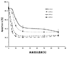
- the obtained labeled Jurkat cells were diluted with PBS (phosphate buffered saline) to 1 ⁇ 10 7 cells / mL to prepare a Jurkat cell suspension.
- Jurkat cell suspension 0% (100: 0), 5% (95: 5), 10% (90:10), 20% (80:20), 50% (50:50) blood by volume
- the mixed solutions [1] to [6] were prepared so as to have a concentration of 70% (30:70).
- Each of the mixed liquids [1] to [6] was filled in a quartz tube having a length of 50 mm and irradiated with ultraviolet light using a spectroscopic irradiator.
- the ultraviolet light to be irradiated has an irradiation wavelength of 290 nm, and the irradiation amount is 10 mJ / cm 2 (irradiance: 0.16 mW / cm 2 , irradiation time: 63 seconds).
- Quartz thin tubes having inner diameters of 200 ⁇ m, 300 ⁇ m, 600 ⁇ m, and 900 ⁇ m were used, respectively. The outer diameters of the quartz tubules are all 3 mm.
- the mixed solutions [1] to [6] were collected, added with a culture solution, cultured at 37 ° C. under 5% CO 2 for 24 hours, and then subjected to FACS (fluorescence activated cell sorting) analysis. Then, the induction ratio of AnnexinV positive, that is, apoptosis of labeled Jurkat cells was examined. The results are shown in FIG.
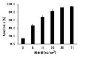
- Jurkat cell suspension A mixed solution [A] was prepared such that the blood had a volume ratio of 20% (80:20).
- the experimental photopheresis device shown in FIG. 8 was produced. Specifically, infusion tubes 73 and 74 each made of a silicon tube are attached to both ends of a quartz thin tube 70 having a length of 50 mm, an outer diameter of 3 mm, and an inner diameter of 300 ⁇ m, and one infusion tube 73 has a transport pump made of a peristaltic pump. 77 was interposed. An LED irradiator 80 is provided above the quartz thin tube 70 so that the quartz thin tube 70 is irradiated with ultraviolet light.
- an ultraviolet light irradiation treatment was performed by irradiating ultraviolet light having an irradiation wavelength of 290 nm with the LED irradiator 80 while circulating the mixed solution [A] through a quartz capillary.
- the mixed solution [A] (indicated by symbol SA in FIG. 8) put in the supply sample tube 78 is transported to the quartz capillary 70 via the infusion tube 73 by the transport pump 77, and the quartz capillary 70 and the other infusion tube 74 were collected in the collection sample tube 79 while being circulated.
- the flow rate of the mixed solution [A] was set to a flow rate at which the passage time of the quartz thin tube, that is, the ultraviolet light irradiation time was 5.6 seconds.
- the ultraviolet light irradiation treatment was performed on conditions where the irradiation amount of the ultraviolet light becomes 0mJ / cm 2, 6mJ / cm 2, 11mJ / cm 2, 20mJ / cm 2, 35mJ / cm 2, 71mJ / cm 2.
- the irradiation amount of ultraviolet light was changed by changing the irradiance by current control according to Table 1. After irradiation with ultraviolet light, the mixed solution [A] was recovered, and the culture solution was added, followed by culturing at 37 ° C.
Landscapes
- Health & Medical Sciences (AREA)
- Heart & Thoracic Surgery (AREA)
- Vascular Medicine (AREA)
- Biomedical Technology (AREA)
- Engineering & Computer Science (AREA)
- Anesthesiology (AREA)
- Cardiology (AREA)
- Hematology (AREA)
- Life Sciences & Earth Sciences (AREA)
- Animal Behavior & Ethology (AREA)
- General Health & Medical Sciences (AREA)
- Public Health (AREA)
- Veterinary Medicine (AREA)
- External Artificial Organs (AREA)
Abstract
La présente invention aborde le problème consistant à fournir : un procédé d'irradiation par ultraviolets pour la photophérèse qui peut induire une tolérance immunitaire, avec une probabilité élevée, à une cellule à traiter contenue dans un échantillon liquide pour la photophérèse par induction de l'apoptose dans la cellule ou par endommagement de la cellule même si aucun processus compliqué tel qu'une séparation centrifuge n'est nécessaire; un micro-dispositif destiné à être utilisé pour le procédé d'irradiation par ultraviolets; et un dispositif d'irradiation aux ultraviolets pour la photophérèse qui comprend le micro-dispositif. Ce procédé d'irradiation par ultraviolets comprend : une étape d'introduction d'un échantillon liquide pour la photophérèse dans un canal d'écoulement d'une partie paroi du micro-dispositif pour la photophérèse; et une étape d'irradiation de l'échantillon liquide pour la photophérèse avec un rayonnement ultraviolet à travers la partie paroi La longueur du canal d'écoulement dans une direction d'irradiation du rayonnement ultraviolet est de 70 à 500 µm.
Applications Claiming Priority (2)
| Application Number | Priority Date | Filing Date | Title |
|---|---|---|---|
| JP2018-078869 | 2018-04-17 | ||
| JP2018078869A JP7184247B2 (ja) | 2018-04-17 | 2018-04-17 | フォトフェレーシスのための紫外光照射方法、フォトフェレーシス用マイクロデバイス、および、フォトフェレーシス用紫外光照射装置 |
Publications (1)
| Publication Number | Publication Date |
|---|---|
| WO2019203065A1 true WO2019203065A1 (fr) | 2019-10-24 |
Family
ID=68240145
Family Applications (1)
| Application Number | Title | Priority Date | Filing Date |
|---|---|---|---|
| PCT/JP2019/015477 Ceased WO2019203065A1 (fr) | 2018-04-17 | 2019-04-09 | Procédé d'irradiation par ultraviolets pour la photophérèse, micro-dispositif pour la photophérèse, et dispositif d'irradiation par ultraviolets pour la photophérèse |
Country Status (2)
| Country | Link |
|---|---|
| JP (1) | JP7184247B2 (fr) |
| WO (1) | WO2019203065A1 (fr) |
Cited By (2)
| Publication number | Priority date | Publication date | Assignee | Title |
|---|---|---|---|---|
| WO2022004136A1 (fr) * | 2020-06-30 | 2022-01-06 | 公立大学法人名古屋市立大学 | Procédé d'induction de lymphocytes t régulateurs |
| WO2024176899A1 (fr) * | 2023-02-22 | 2024-08-29 | 公立大学法人名古屋市立大学 | Dispositif d'irradiation uv pour induction de lymphocytes t régulateurs et procédé de production de lymphocytes t régulateurs. |
Citations (3)
| Publication number | Priority date | Publication date | Assignee | Title |
|---|---|---|---|---|
| JPH05137784A (ja) * | 1991-11-15 | 1993-06-01 | Nissho Corp | 血液の紫外線照射方法 |
| JP2004202235A (ja) * | 2002-12-20 | 2004-07-22 | Therakos Inc | 照射チャンバー |
| WO2012114720A1 (fr) * | 2011-02-22 | 2012-08-30 | 国立大学法人信州大学 | Réacteur optique et son procédé de fabrication |
-
2018
- 2018-04-17 JP JP2018078869A patent/JP7184247B2/ja active Active
-
2019
- 2019-04-09 WO PCT/JP2019/015477 patent/WO2019203065A1/fr not_active Ceased
Patent Citations (3)
| Publication number | Priority date | Publication date | Assignee | Title |
|---|---|---|---|---|
| JPH05137784A (ja) * | 1991-11-15 | 1993-06-01 | Nissho Corp | 血液の紫外線照射方法 |
| JP2004202235A (ja) * | 2002-12-20 | 2004-07-22 | Therakos Inc | 照射チャンバー |
| WO2012114720A1 (fr) * | 2011-02-22 | 2012-08-30 | 国立大学法人信州大学 | Réacteur optique et son procédé de fabrication |
Cited By (4)
| Publication number | Priority date | Publication date | Assignee | Title |
|---|---|---|---|---|
| WO2022004136A1 (fr) * | 2020-06-30 | 2022-01-06 | 公立大学法人名古屋市立大学 | Procédé d'induction de lymphocytes t régulateurs |
| CN115349011A (zh) * | 2020-06-30 | 2022-11-15 | 公立大学法人名古屋市立大学 | 调节性t细胞的诱导方法 |
| JP7550420B2 (ja) | 2020-06-30 | 2024-09-13 | 公立大学法人名古屋市立大学 | 制御性t細胞の誘導方法 |
| WO2024176899A1 (fr) * | 2023-02-22 | 2024-08-29 | 公立大学法人名古屋市立大学 | Dispositif d'irradiation uv pour induction de lymphocytes t régulateurs et procédé de production de lymphocytes t régulateurs. |
Also Published As
| Publication number | Publication date |
|---|---|
| JP2019181054A (ja) | 2019-10-24 |
| JP7184247B2 (ja) | 2022-12-06 |
Similar Documents
| Publication | Publication Date | Title |
|---|---|---|
| US5628727A (en) | Extracorporeal virioncidal apparatus | |
| JP3051998B2 (ja) | 光活性療法及び細胞分離技術を用いる血液のような液体中の遊離の及び同伴された汚染物を同時に除去するためのシステム並びに方法 | |
| AU747412B2 (en) | Septicaemia prevention and treatment system | |
| US20160058937A1 (en) | Blood cleansing and apparatus & method | |
| CZ302538B6 (cs) | Systém pro stanovení hodnoty svetelné energie tekutiny pro prenesení na biologickou tekutinu obsahující cílové objekty | |
| CN101239075B (zh) | 血小板水溶液产品 | |
| CN1104191C (zh) | 处理体液的方法和装置 | |
| JP6756474B2 (ja) | 単核細胞の採集のための方法とシステム | |
| JP6632359B2 (ja) | 体外フォトフェレーシスにおいて照射受光部を用いて最小ヘマトクリットを検出するためのシステムと方法 | |
| EP0138489B1 (fr) | Appareil et procédés pour traiter des cellules par irradiation | |
| JPH05505128A (ja) | 液体中の汚染物を根絶するシステム及び方法 | |
| JPH11505269A (ja) | 血漿中の遊離の及び取り込まれた汚染因子を除去するためのシステム及び方法 | |
| NO803706L (no) | Fremgangsmaate og system til behandling av blod. | |
| US8454839B2 (en) | Method for modifying the properties of a fluid by irradiation, and system for implementing same | |
| WO2019203065A1 (fr) | Procédé d'irradiation par ultraviolets pour la photophérèse, micro-dispositif pour la photophérèse, et dispositif d'irradiation par ultraviolets pour la photophérèse | |
| US20150122738A1 (en) | Blood Cleansing System & Method | |
| Che et al. | Effects of cell salvage on erythrocyte 2, 3‐disphosphoglycerate and G‐6‐PD levels and phosphatidylserine expression | |
| JP7550420B2 (ja) | 制御性t細胞の誘導方法 | |
| US20150121808A1 (en) | Blood cleansing system | |
| US11672898B2 (en) | Microfluidic removal of excess bilirubin from blood | |
| Lee et al. | Engineering aspects of extracorporeal photochemotherapy | |
| JP4615211B2 (ja) | 照射チャンバー | |
| EP2859915A1 (fr) | Dispositif de photobiomodulation sanguine pendant la circulation extracorporelle | |
| US6970740B2 (en) | UVC rediation therapy for leukemia | |
| WO2001080939A2 (fr) | Therapie par rayonnement ultraviolet c pour leucemie lymphoide chronique |
Legal Events
| Date | Code | Title | Description |
|---|---|---|---|
| 121 | Ep: the epo has been informed by wipo that ep was designated in this application |
Ref document number: 19787962 Country of ref document: EP Kind code of ref document: A1 |
|
| NENP | Non-entry into the national phase |
Ref country code: DE |
|
| 122 | Ep: pct application non-entry in european phase |
Ref document number: 19787962 Country of ref document: EP Kind code of ref document: A1 |