WO2019203076A1 - Bobine et moteur utilisant cette dernière - Google Patents
Bobine et moteur utilisant cette dernière Download PDFInfo
- Publication number
- WO2019203076A1 WO2019203076A1 PCT/JP2019/015538 JP2019015538W WO2019203076A1 WO 2019203076 A1 WO2019203076 A1 WO 2019203076A1 JP 2019015538 W JP2019015538 W JP 2019015538W WO 2019203076 A1 WO2019203076 A1 WO 2019203076A1
- Authority
- WO
- WIPO (PCT)
- Prior art keywords
- coil
- conducting wire
- turn
- turns
- motor
- Prior art date
- Legal status (The legal status is an assumption and is not a legal conclusion. Google has not performed a legal analysis and makes no representation as to the accuracy of the status listed.)
- Ceased
Links
Images





Classifications
-
- H—ELECTRICITY
- H02—GENERATION; CONVERSION OR DISTRIBUTION OF ELECTRIC POWER
- H02K—DYNAMO-ELECTRIC MACHINES
- H02K1/00—Details of the magnetic circuit
- H02K1/06—Details of the magnetic circuit characterised by the shape, form or construction
- H02K1/12—Stationary parts of the magnetic circuit
- H02K1/14—Stator cores with salient poles
- H02K1/146—Stator cores with salient poles consisting of a generally annular yoke with salient poles
- H02K1/148—Sectional cores
-
- H—ELECTRICITY
- H01—ELECTRIC ELEMENTS
- H01F—MAGNETS; INDUCTANCES; TRANSFORMERS; SELECTION OF MATERIALS FOR THEIR MAGNETIC PROPERTIES
- H01F27/00—Details of transformers or inductances, in general
- H01F27/28—Coils; Windings; Conductive connections
- H01F27/2823—Wires
-
- H—ELECTRICITY
- H02—GENERATION; CONVERSION OR DISTRIBUTION OF ELECTRIC POWER
- H02K—DYNAMO-ELECTRIC MACHINES
- H02K1/00—Details of the magnetic circuit
- H02K1/06—Details of the magnetic circuit characterised by the shape, form or construction
- H02K1/12—Stationary parts of the magnetic circuit
- H02K1/14—Stator cores with salient poles
-
- H—ELECTRICITY
- H02—GENERATION; CONVERSION OR DISTRIBUTION OF ELECTRIC POWER
- H02K—DYNAMO-ELECTRIC MACHINES
- H02K3/00—Details of windings
- H02K3/04—Windings characterised by the conductor shape, form or construction, e.g. with bar conductors
-
- H—ELECTRICITY
- H02—GENERATION; CONVERSION OR DISTRIBUTION OF ELECTRIC POWER
- H02K—DYNAMO-ELECTRIC MACHINES
- H02K3/00—Details of windings
- H02K3/04—Windings characterised by the conductor shape, form or construction, e.g. with bar conductors
- H02K3/18—Windings for salient poles
-
- H—ELECTRICITY
- H02—GENERATION; CONVERSION OR DISTRIBUTION OF ELECTRIC POWER
- H02K—DYNAMO-ELECTRIC MACHINES
- H02K3/00—Details of windings
- H02K3/46—Fastening of windings on the stator or rotor structure
-
- H—ELECTRICITY
- H02—GENERATION; CONVERSION OR DISTRIBUTION OF ELECTRIC POWER
- H02K—DYNAMO-ELECTRIC MACHINES
- H02K1/00—Details of the magnetic circuit
- H02K1/06—Details of the magnetic circuit characterised by the shape, form or construction
- H02K1/22—Rotating parts of the magnetic circuit
- H02K1/32—Rotating parts of the magnetic circuit with channels or ducts for flow of cooling medium
-
- H—ELECTRICITY
- H02—GENERATION; CONVERSION OR DISTRIBUTION OF ELECTRIC POWER
- H02K—DYNAMO-ELECTRIC MACHINES
- H02K15/00—Processes or apparatus specially adapted for manufacturing, assembling, maintaining or repairing of dynamo-electric machines
- H02K15/04—Processes or apparatus specially adapted for manufacturing, assembling, maintaining or repairing of dynamo-electric machines of windings prior to their mounting into the machines
- H02K15/043—Processes or apparatus specially adapted for manufacturing, assembling, maintaining or repairing of dynamo-electric machines of windings prior to their mounting into the machines winding flat conductive wires or sheets
- H02K15/0431—Concentrated windings
-
- H—ELECTRICITY
- H02—GENERATION; CONVERSION OR DISTRIBUTION OF ELECTRIC POWER
- H02K—DYNAMO-ELECTRIC MACHINES
- H02K2203/00—Specific aspects not provided for in the other groups of this subclass relating to the windings
- H02K2203/09—Machines characterised by wiring elements other than wires, e.g. bus rings, for connecting the winding terminations
-
- H—ELECTRICITY
- H02—GENERATION; CONVERSION OR DISTRIBUTION OF ELECTRIC POWER
- H02K—DYNAMO-ELECTRIC MACHINES
- H02K3/00—Details of windings
- H02K3/32—Windings characterised by the shape, form or construction of the insulation
Definitions
- the present disclosure relates to a coil formed by winding a conducting wire having a square cross section and a motor using the coil.
- the coil is spirally wound around the teeth provided on the stator in the slot.
- the magnetic field strength generated in the coil changes in strength each time an external current is supplied and an external current is supplied.
- an eddy current as shown by an arrow A in FIG. 10 is induced in the coil.
- FIG. 10 is an explanatory diagram of the eddy current A generated in the conventional coil 5.
- the resistivity of the coil material, or the operating conditions of the coil the heat generation of the coil increases. If the loss due to the heat generation cannot be ignored, problems such as a reduction in the efficiency of the motor have occurred.
- An object of the present disclosure is to realize a coil that can reduce eddy current induced in a field magnet by energization of an armature coil and reduce power loss due to eddy current loss, and a motor using the same. is there.
- a coil according to the present disclosure includes a first to nth turns (n is an integer of 3 or more) in which conductive wires having a quadrangular cross section are spirally wound and stacked.
- n is an integer of 3 or more
- the outer surface located on the opposite side to the center of the turn train extends along a plane intersecting the turn train.
- the concave portion provided in the conductive wire inside the teeth and long in the Z-axis direction that is the motor rotation shaft is provided from both circumferential directions.
- the recess provided in the conducting wire on the top side of the coil or the bottom side of the coil is provided in the Z-axis direction that is the motor rotation axis. According to these configurations, it is possible to reduce eddy currents generated in each coil axis. Furthermore, when there are a plurality of recesses provided on the conductor of one axis, it is possible to reduce the loop length of eddy current generated in the conductor by alternately providing recesses on the conductors on each straight line. ,preferable.
- the concave portion By providing the concave portion, the eddy current generated in the linear component of the conductive wire is divided, and an eddy current reduction effect is produced. For this reason, the effect of lowering eddy current loss can be expected by providing more recesses.
- a conventional conductor is cut, a portion having a smaller cross-sectional area with respect to the direction of current flow occurs. For this reason, the resistance in a conducting wire becomes large and the generated Joule heat becomes larger. For this reason, it is preferable to provide the recesses in a balance of both the effect of reducing the eddy current by providing the recesses and the Joule heat due to the increase in the wire resistance.
- the motor of the present disclosure includes a stator having a stator core, teeth protruding from the stator core, and coils of the present disclosure wound around the teeth.
- the eddy current loss of the coil can be reduced.
- a highly efficient motor can be realized.
- FIG. 1C is a cross-sectional view taken along line 1C-1C in FIG. 1B. It is a perspective view which shows the coil which concerns on embodiment. It is a side view which shows the coil which concerns on embodiment. It is a perspective view which shows the coil for embodiment and comparison. It is a side view which shows the coil for embodiment and a comparison. It is explanatory drawing of the eddy current which generate
- FIG. 10 is a front view showing a coil according to Modification 2.
- FIG. 10 is a front view showing another coil according to Modification 2.
- FIG. It is sectional drawing which shows the coil which concerns on embodiment. 10 is a cross-sectional view showing a coil according to Modification 3.
- FIG. It is explanatory drawing of the eddy current which generate
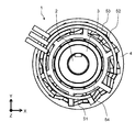
- FIG. 1A is a top view showing a motor 1 according to an embodiment.
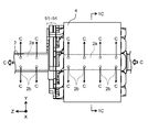
- FIG. 1B is a side view showing the motor 1 according to the embodiment.
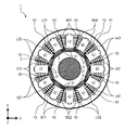
- 1C is a cross-sectional view taken along line 1C-1C in FIG. 1B.
- the motor 1 includes a shaft 2, a rotor 3, a stator 4, coils U11, U22, U32, U41, V12, V21, V31, V42, W11, W22, W32 in a cover case (not shown). W41 and bus bars 51 to 54 are provided.
- the longitudinal direction of the shaft 2 (direction perpendicular to the paper surface of FIG. 1A) is referred to as the Z-axis direction, and the direction orthogonal to this (direction parallel to the paper surface of FIG. 1A) is the X-axis direction and Y-axis direction.
- the X-axis direction and the Y-axis direction are orthogonal to each other.
- integrated or “integrated” means that a plurality of parts are not only mechanically connected by bolting or caulking, but also by material bonding such as covalent bonding, ionic bonding, and metal bonding.
- material bonding such as covalent bonding, ionic bonding, and metal bonding.
- the shaft 2 has a hollow portion 2a extending in the Z-axis direction inside.
- a plurality of through holes 2 b are provided on the side surface of the shaft 2.
- the hollow portion 2 a is a passage for the refrigerant C for cooling the inside of the motor 1.
- the refrigerant C flows in the hollow portion 2 a along the Z-axis direction, and circulates in the motor 1. Further, a part of the refrigerant C flowing through the hollow portion 2a flows out from the plurality of through holes 2b, and flows also from the center side of the motor 1 to the outside, that is, from the rotor 3 to the direction where the stator 4 is located. Cool down.
- the rotor 3 is provided in contact with the outer periphery of the shaft 2.
- the rotor 3 includes magnets 31 in which N poles and S poles are arranged alternately along the outer circumferential direction of the shaft 2 so as to face the stator 4.
- a neodymium magnet is used as the magnet 31 used in the rotor 3.
- the material, shape, and material can be appropriately changed according to the output of the motor.
- the stator 4 has a substantially annular stator core 41, a plurality of teeth 42 provided at equal intervals along the inner periphery thereof, and slots 43 provided between the teeth 42, respectively.
- the stator 4 is disposed outside the rotor 3 with a certain distance from the rotor 3 when viewed from the Z-axis direction.
- the stator core 41 is formed, for example, by punching and processing electromagnetic steel sheets containing silicon or the like.
- the number of magnetic poles of the rotor 3 is five N poles opposed to the stator 4 and five S poles, for a total of 10 poles.
- the number of slots 43 is twelve.
- the present invention is not particularly limited to this, and can be applied to other combinations of the number of magnetic poles and the number of slots.
- the stator 4 has twelve coils U11, U22, U32, U41, V12, V21, V31, V42, W11, W22, W32, and W41. These coils are attached to a predetermined tooth 42 and are disposed in a predetermined slot 43 when viewed from the Z-axis direction. That is, the coils U11, U22, U32, U41, V12, V21, V31, V42, W11, W22, W32, and W41 are concentrated with respect to the teeth 42.
- the coils U11, U22, U32, U41 are integrated with the bus bar 51
- the coils V12, V21, V31, V42 are integrated with the bus bar 52
- the coils W11, W22, W32, W41 are integrated with the bus bar 53, respectively.
- the first letter represents each phase of the motor 1 (in this embodiment, U phase, V phase, W phase).
- the second letter represents the sequence of coils in the same phase.
- the third character represents the winding direction of the coil.
- 1 is a clockwise direction and 2 is a counterclockwise direction. Therefore, the coil U11 indicates that the U-phase arrangement order is the first coil and the winding direction is the clockwise direction.
- Coil V42 is the fourth coil in the V-phase arrangement order, and represents that the winding direction is the counterclockwise direction. Note that clockwise means clockwise when viewed from the center of the motor 1, and “counterclockwise” means counterclockwise when viewed from the center of the motor 1.
- the coils U11 and U41 are U-phase coils, and the coils U22 and U32 are U-bar coils (the direction of the magnetic field generated is opposite to that of the U-phase coil). However, in the following description, unless otherwise specified, they are collectively referred to as U-phase coils.
- the coils V12, V21, V31, and V42 and the coils W11, W22, W32, and W41 are collectively referred to as a V-phase coil and a W-phase coil, respectively.
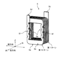
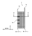
- FIG. 2 is a perspective view showing the coil 5 according to the embodiment.
- FIG. 3 is a side view showing the coil 5 according to the present embodiment.
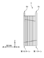
- FIG. 4 is a perspective view showing a coil 5 for comparison with the embodiment.
- FIG. 5 is a side view showing a coil 5 for comparison with the embodiment. 3 and 5 show side views of the coil 5 as seen from the circumferential direction side.
- the coil 5 which concerns on this Embodiment shown in FIG.2 and FIG.3 is the coil U11, U22, U32, U41, V12, V21, V31, V42, W11 with which the teeth 42 of the motor 1 shown to FIG. 1C were mounted
- the coil 5 includes a wound conducting wire 5a, an insulating film 5b provided on the surface of the conducting wire 5a, and lead portions 5c and 5d from the first turn and the tenth turn of the coil 5, respectively.
- the second to tenth turns of the coil 5 are wound in a rectangular shape in plan view, and are composed of four coil sides.
- the conducting wire 5a is a wire made of a conductive member having a square cross section.
- the conducting wire 5a forms a turn train that is spirally wound for 10 turns in a single layer and stacked vertically.
- the conducting wire 5a is made of, for example, copper, aluminum, zinc, magnesium, brass, iron, stainless steel (Steel Use Stainless (SUS)) or the like.
- the part wound from the tip of the drawer part 5c to the lower part of the position where the drawer part 5d is provided is referred to as a first turn, and the subsequent part wound one round at a time Count as turn 10. How to take the starting point of each turn can be determined arbitrarily.
- the side on which the first turn of the coil 5 is provided may be referred to as “outside”, and the side on which the tenth turn is provided may be referred to as “inside”. This is because the outside of the motor is “outside” and the center side of the motor is “inside” with respect to the radial direction of the motor structure.
- the insulating film 5b is provided on the entire surface of the conductive wire 5a so as to insulate the coil 5 from an external member (not shown).
- the coil 5, the stator core 41, and the teeth 42 are insulated by the insulating film 5b and an insulating member (not shown) such as insulating paper.
- an insulating film 5b is made of, for example, polyimide, nylon, polyether ether ketone (Poly Ether Ether Ketone (PEEK)), acrylic, amide imide, ester imide, enamel, heat resistant resin, or the like.
- the thickness of the insulating film 5b is about several tens of ⁇ m, for example, between 10 ⁇ m and 50 ⁇ m.
- the drawer portions 5c and 5d are both part of the conducting wire 5a.
- the lead portions 5c and 5d extend outward from the side surface of the coil 5, in other words, from the plane intersecting the turn row of the conducting wire 5a, in order to receive a current supply from the outside or to supply a current to the outside. ing.
- the lead-out portions 5c and 5d have the insulating film 5b removed in order to connect to an external member, for example, any of the bus bars 51 to 54 shown in FIGS. 1A to 1C.
- the insulating film 5b does not need to be removed in the entire region of the lead portions 5c and 5d. For example, the insulating film 5b may be removed only in a portion necessary for connection with the bus bars 51 to 54.
- an eddy current as shown in FIG. 10 is generated in the linear conductor of each turn.
- the generated eddy current becomes Joule heat, raising the temperature of the motor and lowering the motor efficiency.
- the recesses 5 e and 5 f are provided in the circumferential direction on the conductive wire in the axial direction of a part of the turns inside the teeth 42.
- the size of the provided recesses 5e and 5f is about 1/3 of the coil width so as not to impair the rigidity of the coil width.
- the recesses 5e and 5f are alternately provided in both the coil circumferential directions.
- the recesses 5e and 5f may be provided on one side of the coil circumferential direction.
- the recesses 5e and 5f are provided in both directions in one axis as shown in FIGS. Is preferred.
- the size of the cut-out recesses 5e and 5f is not limited to about ⁇ ⁇ ⁇ of the coil width, except for the concern of reduced rigidity of the conductor and increased Joule heat due to increased resistance in the conductor. The effect of reducing eddy current is higher when the notch is larger.
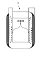
- FIG. 6 is an explanatory diagram of eddy currents generated in the coil according to the embodiment.
- An eddy current as shown by an arrow A in FIG. 6 is induced in the conducting wire provided with the recesses 5e and 5f shown in FIGS.
- the eddy current shown in FIG. 6 is smaller than the eddy current generated in the conventional coil.
- the shape of the recesses 5e and 5f shown in FIGS. 2 and 3 is a quadrangle.
- this shape may be a triangle, a trapezoid, a circle, an inverted triangle, an inverted trapezoid, or the like, and is not limited.
- the shape of the corner portion greatly affects the coil machining accuracy, it may be polygonal, such as with R chamfering or C chamfering.
- the installation of the recesses 5e and 5f shown in FIGS. 2 and 3 is a conductive wire in the axial direction of a part of the turns inside the teeth, but may be a conductive wire on the coil top side or the coil bottom side, and is not limited.
- a natural number of one or more concave portions is provided. For example, when only one is installed on the side, the effect of reducing eddy current loss is higher when the recess is provided inside the coil.
- the eddy current loss reduction effect is higher when the same number of recesses are alternately installed in the circumferential direction of the coil. This is because if the concave portion is unevenly arranged in the circumferential direction of the coil, a long eddy current loop is generated on the coil side where the concave portion is not provided, and the effect of reducing the eddy current loss is reduced.
- the coil 5 includes a first to n-th turns (n is an integer equal to or greater than 3) in which the conductive wires 5a having a quadrangular cross section are spirally wound and stacked.
- n is an integer equal to or greater than 3
- at least a part of the first to n-th turns in the coil 5 is provided with a deformed part that is a concave part having a shape different from that of the other part of the lead 5 a.
- the outer surface located on the opposite side to the center of the turn train extends along a plane intersecting the turn train.
- the number of turns of the coil 5 is 10.
- the number of turns is not particularly limited to this, and other values may be used. That is, in a coil having a turn sequence composed of first to n-th turns (n is an integer of 3 or more) in which a conducting wire having a rectangular cross section is spirally wound and laminated in the radial direction, It is sufficient that a recess is provided in at least a part of the turns, and there is no need to have a recess in all n turns. The installation of the recesses has a concern that the coil cross-sectional area decreases and the Joule heat increases due to an increase in coil conductivity.
- the deforming portion may be provided at least on the nth turn.
- the deforming portion may include a recess cut out in the circumferential direction of the conducting wire in the Z-axis conducting wire that is perpendicular to the radial direction and the circumferential direction of the coil.
- the motor 1 of the present embodiment includes the stator 3 having the rotor 3, the stator core 41, the teeth 42 protruding from the stator core 41, and the coil 5 of the present embodiment wound around the teeth 42. Including.
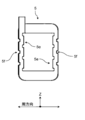
- FIG. 7A is a front view showing the coil 5 according to the embodiment.
- FIG. 7A is a front view of the coil 5 shown in FIGS. 2 and 3 as viewed from the inside to the outside in the coil radial direction.
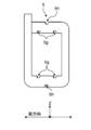
- FIGS. 7B and 7C the front view of the coil 5 according to the first modification viewed from the inner side to the outer side in the coil radial direction is shown in FIGS. 7B and 7C.
- FIG. 7B is a front view showing the coil 5 according to the first modification.
- FIG. 7C is a front view showing another coil 5 according to the first modification.
- FIG. 7A is a front view showing the coil 5 according to the embodiment.
- FIG. 7A only the innermost n-th turn conducting wire in the coil radial direction among the conducting wires with n turns is shown, and the lead wires other than the nth turn and the lead portion 5c are omitted.
- FIG. 7B and FIG. 7C show only one axis part of the conducting wire having the notched recess, omitting the other spirally formed part, the conducting wire other than the n-th turn, and the lead portions 5c and 5d. Yes.
- the coil 5 shown in FIGS. 7A, 7B, and 7C is a recess 5e that is a notch (deformed part) inside the coil inside the teeth, and a notch (deformed part) outside the coil inside the teeth. And a recess 5f.
- the concave shape may be a substantial triangle shown in FIG. 7B, a substantially semicircular shape shown in FIG. 7C, or a trapezoid.
- the recess is cut away with respect to the coil circumferential direction.
- the 7A to 7C have a plurality of recesses. In that case, it is desirable to have a recess on both sides in the coil circumferential direction.
- the number of recesses 5e on the inner side in the coil radial direction is preferably the same as or one more than the number of recesses 5f on the outer side of the conducting wire.
- the concave portion 5e is provided on the inner side of the spirally formed conducting wire.
- the recess 5e inside the conductor and the recess 5f outside the conductor should be both in the coil circumferential direction and not in the same position in the Z-axis direction. desirable.
- the number of recesses inside the coil 5 is preferably equal to or greater than the number of recesses outside the coil 5.
- the deformed portion is such that the concave portion inside the conductive wire and the concave portion outside the conductive wire are not in the same position with respect to the Z-axis direction.
- the number of turns of the coil 5 is 10.
- the number of turns is not particularly limited to this, and other values may be used.
- FIG. 8A is a front view showing the coil according to the embodiment.
- FIG. 8A is a front view of the coil 5 shown in FIGS. 2 and 3 as viewed from the inner side to the outer side in the coil radial direction.
- FIGS. 8B and 8C the front view of the coil 5 according to the second modification viewed from the inner side to the outer side in the coil radial direction is shown in FIGS. 8B and 8C.
- FIG. 8B is a front view showing a coil according to the second modification.
- FIG. 8C is a front view showing another coil according to the second modification. 8A, FIG. 8B, and FIG. 8C, only the innermost n-th turn of the conductive wires having n turns is shown in FIG. 8A, and the lead wires other than the n-th turn and the lead-out portion 5c are omitted. ing.
- the recess of the coil 5 shown in FIGS. 8A, 2 and 3 is notched only in the Z-axis direction of the conducting wire.
- FIG. 8B and FIG. 8C shown in this modified example concave portions are provided in the top portion of the coil and the bottom portion of the coil.
- the recessed part cut out inside the coil is shown as 5g
- the recessed part cut out outside the coil is shown as 5h.
- the coil 5 shown in FIGS. 8B and 8C includes a recess 5g that is a notch (deformed portion) inside the coil at the top and bottom of the teeth, and a coil outside of the coil at the top and bottom of the teeth. And a recess 5h which is a notch (deformed portion).
- the concave portion 5e, the concave portion 5f, the concave portion 5g, and the concave portion 5h may be all installed, or may be installed on a part of any one of the sides.
- FIG. 8C shows an example in which a recess 5e, a recess 5f, a recess 5g, and a recess 5h are provided on all sides.
- the locations of the recess 5e, the recess 5f, the recess 5g, and the recess 5h are not limited.
- the number of recesses is 5 or 3 on each side, but is not particularly limited to this, and may be another value.
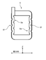
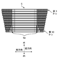
- FIG. 9A is a cross-sectional view showing the coil 5 according to the embodiment.
- FIG. 9A shows a cross section of the coil 5 taken along the line 1C-1C shown in FIG. 1B and a cut surface taken along the 1-axis shown in FIG. 3 in the Z-axis direction.
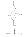
- FIG. 9B is shown for comparison of the coil 5 according to this modification.
- FIG. 9B is a cross-sectional view showing the coil 5 according to the third modification.
- illustration of the tooth part inside the coil is omitted.
- the recess 5e provided in FIG. 9A is provided from the eighth turn to the tenth turn.
- the cutouts are all the same size.
- FIG. 9B shown in this modification the notch degree of the recessed part 5e of a conducting wire is not the same, but the inner conducting wire is greatly cut out in the radial direction. Since the eddy current generated on the inner side in the coil radial direction is larger than the eddy current generated on the outer side in the coil radial direction, the notch size of the recess 5e is differentiated. Furthermore, as shown in FIG. 6, in the 8th turn to the 10th turn, also in the part where the recess 5e is not cut, the width dimension in the circumferential direction of the conducting wire is narrowed, and a gap 5j is formed between the teeth part. Form.
- the notch of the conductive wire becomes larger toward the inner side in the radial direction of the coil 5.
- the recess 5e is installed only in the three turns on the radially inner side from the eighth turn to the tenth turn of the coil 5, but is not particularly limited thereto. It may be a value.
- the number of turns of the coil 5 is 10, but the number of turns is not particularly limited to this, and other values may be used.
- the coil 5 can be formed by casting. According to this method, a conducting wire having a large cross-sectional area can be easily formed into a spiral wound coil. However, it is not limited to casting, and may be formed by other methods.
- the cutting may be performed from a solid material such as copper, aluminum, zinc, magnesium, iron, SUS, or brass. For example, you may form the components shape
- the coil according to the present disclosure can reduce the generation of eddy currents, and is useful when applied to a motor or a power device.
Landscapes
- Engineering & Computer Science (AREA)
- Power Engineering (AREA)
- Windings For Motors And Generators (AREA)
- Coils Of Transformers For General Uses (AREA)
Abstract
Priority Applications (4)
| Application Number | Priority Date | Filing Date | Title |
|---|---|---|---|
| EP19788724.3A EP3783629B1 (fr) | 2018-04-18 | 2019-04-10 | Bobine et moteur utilisant cette dernière |
| CN201980025986.9A CN111971763B (zh) | 2018-04-18 | 2019-04-10 | 线圈以及使用该线圈的电动机 |
| US17/041,019 US11411452B2 (en) | 2018-04-18 | 2019-04-10 | Coil and motor using same |
| JP2020514098A JP7257602B2 (ja) | 2018-04-18 | 2019-04-10 | コイル |
Applications Claiming Priority (2)
| Application Number | Priority Date | Filing Date | Title |
|---|---|---|---|
| JP2018-079731 | 2018-04-18 | ||
| JP2018079731 | 2018-04-18 |
Publications (1)
| Publication Number | Publication Date |
|---|---|
| WO2019203076A1 true WO2019203076A1 (fr) | 2019-10-24 |
Family
ID=68239510
Family Applications (1)
| Application Number | Title | Priority Date | Filing Date |
|---|---|---|---|
| PCT/JP2019/015538 Ceased WO2019203076A1 (fr) | 2018-04-18 | 2019-04-10 | Bobine et moteur utilisant cette dernière |
Country Status (5)
| Country | Link |
|---|---|
| US (1) | US11411452B2 (fr) |
| EP (1) | EP3783629B1 (fr) |
| JP (1) | JP7257602B2 (fr) |
| CN (1) | CN111971763B (fr) |
| WO (1) | WO2019203076A1 (fr) |
Cited By (6)
| Publication number | Priority date | Publication date | Assignee | Title |
|---|---|---|---|---|
| WO2021117320A1 (fr) * | 2019-12-12 | 2021-06-17 | パナソニックIpマネジメント株式会社 | Bobine et moteur la comprenant |
| EP3958442A3 (fr) * | 2020-08-19 | 2022-03-02 | Honeywell International Inc. | Enroulement de stator de machine électrique |
| JP2023140069A (ja) * | 2022-03-22 | 2023-10-04 | 三菱重工業株式会社 | コイルの製造方法、コイル、及び電動機 |
| EP4160878A4 (fr) * | 2020-05-29 | 2023-12-06 | Panasonic Intellectual Property Management Co., Ltd. | Bobine, stator comprenant ladite bobine et moteur |
| WO2024154677A1 (fr) * | 2023-01-17 | 2024-07-25 | パナソニックIpマネジメント株式会社 | Moteur |
| WO2026126661A1 (fr) * | 2024-12-10 | 2026-06-18 | 三菱電機株式会社 | Induit, moteur et procédé de production d'induit |
Families Citing this family (4)
| Publication number | Priority date | Publication date | Assignee | Title |
|---|---|---|---|---|
| CN111971763B (zh) * | 2018-04-18 | 2024-06-14 | 松下知识产权经营株式会社 | 线圈以及使用该线圈的电动机 |
| CN114846728A (zh) * | 2019-12-27 | 2022-08-02 | 松下知识产权经营株式会社 | 线圈以及具备该线圈的定子、马达 |
| US11894756B2 (en) * | 2021-01-25 | 2024-02-06 | Honeywell International Inc. | Systems and methods for electric propulsion systems for electric engines |
| US12633791B2 (en) | 2023-11-15 | 2026-05-19 | General Electric Deutschland Holding Gmbh | Electric machine coil configuration and electric machines having the same |
Citations (5)
| Publication number | Priority date | Publication date | Assignee | Title |
|---|---|---|---|---|
| JPS539595B2 (fr) | 1973-10-26 | 1978-04-06 | ||
| JPS56164656U (fr) * | 1980-05-07 | 1981-12-07 | ||
| JPS56164654U (fr) * | 1980-05-07 | 1981-12-07 | ||
| WO2003041244A1 (fr) * | 2001-11-08 | 2003-05-15 | Matsushita Electric Industrial Co., Ltd. | Moteur |
| JP2015228476A (ja) * | 2014-06-03 | 2015-12-17 | 株式会社デンソー | コイル装置およびコイル装置の製造方法 |
Family Cites Families (17)
| Publication number | Priority date | Publication date | Assignee | Title |
|---|---|---|---|---|
| JPS56164654A (en) * | 1980-05-23 | 1981-12-17 | Tech Res & Dev Inst Of Japan Def Agency | Data transmitting and receiving device |
| CN2289288Y (zh) * | 1997-01-30 | 1998-08-26 | 华中理工大学 | 箔式空心电抗器 |
| JPH1198744A (ja) * | 1997-09-19 | 1999-04-09 | Toshiba Corp | 回転電機の回転子 |
| JP4581188B2 (ja) * | 2000-06-13 | 2010-11-17 | 日産自動車株式会社 | 平角線構造及び平角線の巻線方法 |
| JP3618079B2 (ja) * | 2000-07-11 | 2005-02-09 | 株式会社モステック | 多本線台形状コイルと、そのコイルの製造方法および製造装置 |
| JP4691275B2 (ja) * | 2001-06-28 | 2011-06-01 | 澤藤電機株式会社 | スタータの巻線構造 |
| DE102004044986A1 (de) * | 2004-09-16 | 2006-04-06 | Siemens Ag | Permanenterregte Synchronmaschine mit Flachdrahtwicklungen |
| JP5309595B2 (ja) | 2008-02-19 | 2013-10-09 | 住友電気工業株式会社 | 導線をコイルとして用いてなるモータ、リアクトル、前記導線の製造方法 |
| JP5434227B2 (ja) * | 2009-04-20 | 2014-03-05 | トヨタ自動車株式会社 | ステータ、及びステータ製造方法 |
| JP2011234443A (ja) * | 2010-04-26 | 2011-11-17 | Aisin Seiki Co Ltd | コイルおよび電機子 |
| DE102012212637A1 (de) | 2012-07-18 | 2014-01-23 | Fraunhofer-Gesellschaft zur Förderung der angewandten Forschung e.V. | Gießtechnisch hergestellte elektrische Spule |
| KR101565700B1 (ko) * | 2014-06-24 | 2015-11-03 | 삼성전기주식회사 | 칩 전자부품, 이의 제조방법 및 그 실장기판 |
| CN204242763U (zh) * | 2014-09-12 | 2015-04-01 | 昱京科技股份有限公司 | 适用于片状卷绕绕组的铁芯结构 |
| CN206758245U (zh) * | 2017-06-15 | 2017-12-15 | 深圳市信维通信股份有限公司 | 一种用于无线充电设备的感应线圈结构 |
| CN111971763B (zh) * | 2018-04-18 | 2024-06-14 | 松下知识产权经营株式会社 | 线圈以及使用该线圈的电动机 |
| JP2020137371A (ja) * | 2019-02-25 | 2020-08-31 | 株式会社デンソー | 電機子及び回転電機 |
| US20200328011A1 (en) * | 2019-04-12 | 2020-10-15 | Goto Denshi Co., Ltd. | Electric wire for high frequency, high voltage and large current |
-
2019
- 2019-04-10 CN CN201980025986.9A patent/CN111971763B/zh active Active
- 2019-04-10 US US17/041,019 patent/US11411452B2/en active Active
- 2019-04-10 EP EP19788724.3A patent/EP3783629B1/fr active Active
- 2019-04-10 JP JP2020514098A patent/JP7257602B2/ja active Active
- 2019-04-10 WO PCT/JP2019/015538 patent/WO2019203076A1/fr not_active Ceased
Patent Citations (5)
| Publication number | Priority date | Publication date | Assignee | Title |
|---|---|---|---|---|
| JPS539595B2 (fr) | 1973-10-26 | 1978-04-06 | ||
| JPS56164656U (fr) * | 1980-05-07 | 1981-12-07 | ||
| JPS56164654U (fr) * | 1980-05-07 | 1981-12-07 | ||
| WO2003041244A1 (fr) * | 2001-11-08 | 2003-05-15 | Matsushita Electric Industrial Co., Ltd. | Moteur |
| JP2015228476A (ja) * | 2014-06-03 | 2015-12-17 | 株式会社デンソー | コイル装置およびコイル装置の製造方法 |
Cited By (12)
| Publication number | Priority date | Publication date | Assignee | Title |
|---|---|---|---|---|
| WO2021117320A1 (fr) * | 2019-12-12 | 2021-06-17 | パナソニックIpマネジメント株式会社 | Bobine et moteur la comprenant |
| JPWO2021117320A1 (fr) * | 2019-12-12 | 2021-06-17 | ||
| JP7599070B2 (ja) | 2019-12-12 | 2024-12-13 | パナソニックIpマネジメント株式会社 | コイル及びそれを備えたモータ |
| EP4160878A4 (fr) * | 2020-05-29 | 2023-12-06 | Panasonic Intellectual Property Management Co., Ltd. | Bobine, stator comprenant ladite bobine et moteur |
| US12273001B2 (en) | 2020-05-29 | 2025-04-08 | Panasonic Intellectual Property Management Co., Ltd. | Coil, stator comprising same, and motor |
| EP3958442A3 (fr) * | 2020-08-19 | 2022-03-02 | Honeywell International Inc. | Enroulement de stator de machine électrique |
| US11949302B2 (en) | 2020-08-19 | 2024-04-02 | Honeywell International Inc. | Electric machine stator winding |
| JP2023140069A (ja) * | 2022-03-22 | 2023-10-04 | 三菱重工業株式会社 | コイルの製造方法、コイル、及び電動機 |
| JP7798638B2 (ja) | 2022-03-22 | 2026-01-14 | 三菱重工業株式会社 | コイルの製造方法 |
| US12603553B2 (en) | 2022-03-22 | 2026-04-14 | Mitsubishi Heavy Industries, Ltd. | Method of manufacturing coil, coil, and electric motor |
| WO2024154677A1 (fr) * | 2023-01-17 | 2024-07-25 | パナソニックIpマネジメント株式会社 | Moteur |
| WO2026126661A1 (fr) * | 2024-12-10 | 2026-06-18 | 三菱電機株式会社 | Induit, moteur et procédé de production d'induit |
Also Published As
| Publication number | Publication date |
|---|---|
| EP3783629B1 (fr) | 2025-08-20 |
| US11411452B2 (en) | 2022-08-09 |
| CN111971763A (zh) | 2020-11-20 |
| EP3783629A1 (fr) | 2021-02-24 |
| CN111971763B (zh) | 2024-06-14 |
| JPWO2019203076A1 (ja) | 2021-05-13 |
| JP7257602B2 (ja) | 2023-04-14 |
| EP3783629A4 (fr) | 2021-05-26 |
| US20210021167A1 (en) | 2021-01-21 |
Similar Documents
| Publication | Publication Date | Title |
|---|---|---|
| JP7257602B2 (ja) | コイル | |
| JP4699961B2 (ja) | 回転電機用コイルとその製造方法、並びに回転電機とその製造方法 | |
| JP7426558B2 (ja) | モータ | |
| JP7300585B2 (ja) | モータ | |
| CN110476326B (zh) | 线圈和使用该线圈的马达 | |
| US11929654B2 (en) | Coil mounting structure | |
| CN110771007A (zh) | 定子和马达 | |
| JP7050234B2 (ja) | モータ | |
| JPWO2018135094A1 (ja) | モータ | |
| JP2016129447A (ja) | 回転電機 | |
| JPWO2018155221A1 (ja) | モータ | |
| JP7386399B2 (ja) | コイルの装着構造、ステータ及びモータ | |
| JP7445926B2 (ja) | コイル装置 | |
| JP7535686B2 (ja) | モータ | |
| JPWO2021095343A5 (fr) |
Legal Events
| Date | Code | Title | Description |
|---|---|---|---|
| 121 | Ep: the epo has been informed by wipo that ep was designated in this application |
Ref document number: 19788724 Country of ref document: EP Kind code of ref document: A1 |
|
| ENP | Entry into the national phase |
Ref document number: 2020514098 Country of ref document: JP Kind code of ref document: A |
|
| NENP | Non-entry into the national phase |
Ref country code: DE |
|
| ENP | Entry into the national phase |
Ref document number: 2019788724 Country of ref document: EP Effective date: 20201118 |
|
| WWG | Wipo information: grant in national office |
Ref document number: 2019788724 Country of ref document: EP |