WO2019203121A1 - Plaque polarisante à couche de différence de phase fixée à celle-ci, et dispositif d'affichage électroluminescent organique - Google Patents
Plaque polarisante à couche de différence de phase fixée à celle-ci, et dispositif d'affichage électroluminescent organique Download PDFInfo
- Publication number
- WO2019203121A1 WO2019203121A1 PCT/JP2019/015822 JP2019015822W WO2019203121A1 WO 2019203121 A1 WO2019203121 A1 WO 2019203121A1 JP 2019015822 W JP2019015822 W JP 2019015822W WO 2019203121 A1 WO2019203121 A1 WO 2019203121A1
- Authority
- WO
- WIPO (PCT)
- Prior art keywords
- layer
- retardation layer
- polarizing plate
- sensitive adhesive
- pressure
- Prior art date
- Legal status (The legal status is an assumption and is not a legal conclusion. Google has not performed a legal analysis and makes no representation as to the accuracy of the status listed.)
- Ceased
Links
Images
Classifications
-
- G—PHYSICS
- G02—OPTICS
- G02B—OPTICAL ELEMENTS, SYSTEMS OR APPARATUS
- G02B5/00—Optical elements other than lenses
- G02B5/30—Polarising elements
- G02B5/3083—Birefringent or phase retarding elements
-
- B—PERFORMING OPERATIONS; TRANSPORTING
- B32—LAYERED PRODUCTS
- B32B—LAYERED PRODUCTS, i.e. PRODUCTS BUILT-UP OF STRATA OF FLAT OR NON-FLAT, e.g. CELLULAR OR HONEYCOMB, FORM
- B32B7/00—Layered products characterised by the relation between layers; Layered products characterised by the relative orientation of features between layers, or by the relative values of a measurable parameter between layers, i.e. products comprising layers having different physical, chemical or physicochemical properties; Layered products characterised by the interconnection of layers
- B32B7/02—Physical, chemical or physicochemical properties
- B32B7/023—Optical properties
-
- B—PERFORMING OPERATIONS; TRANSPORTING
- B32—LAYERED PRODUCTS
- B32B—LAYERED PRODUCTS, i.e. PRODUCTS BUILT-UP OF STRATA OF FLAT OR NON-FLAT, e.g. CELLULAR OR HONEYCOMB, FORM
- B32B7/00—Layered products characterised by the relation between layers; Layered products characterised by the relative orientation of features between layers, or by the relative values of a measurable parameter between layers, i.e. products comprising layers having different physical, chemical or physicochemical properties; Layered products characterised by the interconnection of layers
- B32B7/04—Interconnection of layers
- B32B7/12—Interconnection of layers using interposed adhesives or interposed materials with bonding properties
-
- C—CHEMISTRY; METALLURGY
- C09—DYES; PAINTS; POLISHES; NATURAL RESINS; ADHESIVES; COMPOSITIONS NOT OTHERWISE PROVIDED FOR; APPLICATIONS OF MATERIALS NOT OTHERWISE PROVIDED FOR
- C09J—ADHESIVES; NON-MECHANICAL ASPECTS OF ADHESIVE PROCESSES IN GENERAL; ADHESIVE PROCESSES NOT PROVIDED FOR ELSEWHERE; USE OF MATERIALS AS ADHESIVES
- C09J133/00—Adhesives based on homopolymers or copolymers of compounds having one or more unsaturated aliphatic radicals, each having only one carbon-to-carbon double bond, and at least one being terminated by only one carboxyl radical, or of salts, anhydrides, esters, amides, imides, or nitriles thereof; Adhesives based on derivatives of such polymers
- C09J133/04—Homopolymers or copolymers of esters
-
- C—CHEMISTRY; METALLURGY
- C09—DYES; PAINTS; POLISHES; NATURAL RESINS; ADHESIVES; COMPOSITIONS NOT OTHERWISE PROVIDED FOR; APPLICATIONS OF MATERIALS NOT OTHERWISE PROVIDED FOR
- C09J—ADHESIVES; NON-MECHANICAL ASPECTS OF ADHESIVE PROCESSES IN GENERAL; ADHESIVE PROCESSES NOT PROVIDED FOR ELSEWHERE; USE OF MATERIALS AS ADHESIVES
- C09J7/00—Adhesives in the form of films or foils
- C09J7/30—Adhesives in the form of films or foils characterised by the adhesive composition
- C09J7/38—Pressure-sensitive adhesives [PSA]
-
- G—PHYSICS
- G02—OPTICS
- G02B—OPTICAL ELEMENTS, SYSTEMS OR APPARATUS
- G02B1/00—Optical elements characterised by the material of which they are made; Optical coatings for optical elements
- G02B1/10—Optical coatings produced by application to, or surface treatment of, optical elements
- G02B1/14—Protective coatings, e.g. hard coatings
-
- G—PHYSICS
- G02—OPTICS
- G02B—OPTICAL ELEMENTS, SYSTEMS OR APPARATUS
- G02B5/00—Optical elements other than lenses
- G02B5/30—Polarising elements
-
- G—PHYSICS
- G02—OPTICS
- G02B—OPTICAL ELEMENTS, SYSTEMS OR APPARATUS
- G02B5/00—Optical elements other than lenses
- G02B5/30—Polarising elements
- G02B5/3025—Polarisers, i.e. arrangements capable of producing a definite output polarisation state from an unpolarised input state
- G02B5/3033—Polarisers, i.e. arrangements capable of producing a definite output polarisation state from an unpolarised input state in the form of a thin sheet or foil, e.g. Polaroid
-
- G—PHYSICS
- G09—EDUCATION; CRYPTOGRAPHY; DISPLAY; ADVERTISING; SEALS
- G09F—DISPLAYING; ADVERTISING; SIGNS; LABELS OR NAME-PLATES; SEALS
- G09F9/00—Indicating arrangements for variable information in which the information is built-up on a support by selection or combination of individual elements
- G09F9/30—Indicating arrangements for variable information in which the information is built-up on a support by selection or combination of individual elements in which the desired character or characters are formed by combining individual elements
-
- H—ELECTRICITY
- H05—ELECTRIC TECHNIQUES NOT OTHERWISE PROVIDED FOR
- H05B—ELECTRIC HEATING; ELECTRIC LIGHT SOURCES NOT OTHERWISE PROVIDED FOR; CIRCUIT ARRANGEMENTS FOR ELECTRIC LIGHT SOURCES, IN GENERAL
- H05B33/00—Electroluminescent light sources
- H05B33/02—Details
-
- H—ELECTRICITY
- H10—SEMICONDUCTOR DEVICES; ELECTRIC SOLID-STATE DEVICES NOT OTHERWISE PROVIDED FOR
- H10K—ORGANIC ELECTRIC SOLID-STATE DEVICES
- H10K59/00—Integrated devices, or assemblies of multiple devices, comprising at least one organic light-emitting element covered by group H10K50/00
- H10K59/50—OLEDs integrated with light modulating elements, e.g. with electrochromic elements, photochromic elements or liquid crystal elements
-
- B—PERFORMING OPERATIONS; TRANSPORTING
- B32—LAYERED PRODUCTS
- B32B—LAYERED PRODUCTS, i.e. PRODUCTS BUILT-UP OF STRATA OF FLAT OR NON-FLAT, e.g. CELLULAR OR HONEYCOMB, FORM
- B32B2457/00—Electrical equipment
- B32B2457/20—Displays, e.g. liquid crystal displays, plasma displays
- B32B2457/206—Organic displays, e.g. OLED
-
- H—ELECTRICITY
- H10—SEMICONDUCTOR DEVICES; ELECTRIC SOLID-STATE DEVICES NOT OTHERWISE PROVIDED FOR
- H10K—ORGANIC ELECTRIC SOLID-STATE DEVICES
- H10K59/00—Integrated devices, or assemblies of multiple devices, comprising at least one organic light-emitting element covered by group H10K50/00
- H10K59/80—Constructional details
- H10K59/8791—Arrangements for improving contrast, e.g. preventing reflection of ambient light
Definitions
- the present invention relates to a polarizing plate with a retardation layer and an organic EL display device.
- organic EL display devices In recent years, along with the widespread use of thin displays, image display devices (organic EL display devices) equipped with organic EL panels have been proposed.
- the organic EL panel has a highly reflective metal layer, and is likely to cause problems such as external light reflection and background reflection. Therefore, it is known to prevent these problems by providing a polarizing plate with a retardation layer (circular polarizing plate) on the viewing side.
- a polarizing plate with a retardation layer a laminate in which two retardation layers containing a liquid crystal compound are bonded with an adhesive is used, and the polarizing plate with a retardation layer is used as an adhesive.
- the heat resistance is low, and there may be a problem that a crack occurs in the retardation layer or unevenness occurs. Furthermore, the polarizing plate with a retardation layer is likely to be scratched and may cause problems such as curling.
- the present invention has been made to solve the above-described conventional problems, and its main purpose is to provide a polarizing plate with a retardation layer that has excellent heat resistance, is resistant to scratching, and is unlikely to curl, and such retardation.
- the object is to provide an organic EL display device using a polarizing plate with a layer.
- the polarizing plate with a retardation layer of the present invention comprises a polarizing plate, a first retardation layer, a first adhesive layer, a second retardation layer, and a second adhesive layer in this order.
- the first retardation layer and the second retardation layer contain a liquid crystal compound
- the first pressure-sensitive adhesive layer has a thickness of 8 ⁇ m or less and an elastic modulus at 25 ° C. of 10 5 Pa or more.
- the second pressure-sensitive adhesive layer is composed of a pressure-sensitive adhesive containing 70% by weight or more of alkyl (meth) acrylate in the base polymer, and an elastic modulus at 25 ° C. of 5.0 ⁇ 10 5 Pa or less. It is.
- the polarizing plate with a retardation layer further has a surface protective film on the viewing side of the polarizing plate, and the thickness of the surface protective film is 40 ⁇ m to 90 ⁇ m.
- an organic EL display device is provided. This organic EL display device has the above polarizing plate with a retardation layer.
- the thickness of the first pressure-sensitive adhesive layer is 8 ⁇ m or less
- the elastic modulus at 25 ° C. is from 10 5 Pa to 10 6 Pa
- the second pressure-sensitive adhesive layer has an alkyl ( By including 70% by weight or more of (meth) acrylate and having an elastic modulus at 25 ° C. of 5.0 ⁇ 10 5 Pa or less, a polarizing plate with a retardation layer that is excellent in heat resistance, hardly scratches, and does not curl easily is realized. We were able to.
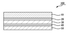
- FIG. 1 is a schematic cross-sectional view of a polarizing plate with a retardation layer according to one embodiment of the present invention.
- the polarizing plate 100 with a retardation layer includes a polarizing plate 10, a first retardation layer 20, a first pressure-sensitive adhesive layer 30, a second retardation layer 40, and a second retardation layer.
- the adhesive layer 50 in this order. That is, the first retardation layer 20 and the second retardation layer 40 are laminated via the first pressure-sensitive adhesive layer 30.
- the first retardation layer 20 and the second retardation layer 40 are configured to include a liquid crystal compound.
- the first pressure-sensitive adhesive layer 30 has an elastic modulus at 25 ° C. of 10 5 Pa to 10 6 Pa.
- the first pressure-sensitive adhesive layer 30 has a thickness of 5 to 30 ⁇ m in one embodiment, and has a thickness of 8 ⁇ m or less in another embodiment.
- the second pressure-sensitive adhesive layer 50 is composed of a pressure-sensitive adhesive containing 70% by weight or more of alkyl (meth) acrylate in the base polymer.
- the second adhesive layer 50 has an elastic modulus at 25 ° C. of 9.0 ⁇ 10 4 Pa or less, and in another embodiment, the elastic modulus at 25 ° C. is 5.0 ⁇ . 10 5 Pa or less.
- the polarizing plate with a retardation layer may further have a surface protective film (not shown) on the viewing side of the polarizing plate.
- the thickness of the surface protective film is 40 ⁇ m to 90 ⁇ m.
- the polarizing plate with a retardation layer 100 is excellent in heat resistance, hardly causes curling, has scratches in the first retardation layer 20 and / or the second retardation layer 40, cracks, and unevenness. The generation of can be suppressed.
- the polarizing plate 10 typically has a polarizer, a first protective layer disposed on one side of the polarizer, and a second protective layer disposed on the other side of the polarizer. .
- the polarizer is typically an absorptive polarizer.
- One of the first protective layer and the second protective layer may be omitted.
- the resin film forming the polarizer may be a single-layer resin film or a laminate of two or more layers.
- polarizers composed of a single-layer resin film include hydrophilic polymer films such as polyvinyl alcohol (PVA) films, partially formalized PVA films, and ethylene / vinyl acetate copolymer partially saponified films.
- PVA polyvinyl alcohol
- polyene-based oriented films such as those subjected to dyeing treatment and stretching treatment with dichroic substances such as iodine and dichroic dyes, PVA dehydrated products and polyvinyl chloride dehydrochlorinated products.
- a polarizer obtained by dyeing a PVA film with iodine and uniaxially stretching is used because of excellent optical properties.
- the dyeing with iodine is performed, for example, by immersing a PVA film in an aqueous iodine solution.
- the stretching ratio of the uniaxial stretching is preferably 3 to 7 times.
- the stretching may be performed after the dyeing treatment or may be performed while dyeing. Moreover, you may dye
- the PVA film is subjected to swelling treatment, crosslinking treatment, washing treatment, drying treatment and the like. For example, by immersing the PVA film in water and washing it before dyeing, not only can the surface of the PVA film be cleaned of dirt and anti-blocking agents, but the PVA film can be swollen to cause uneven staining. Can be prevented.
- a polarizer obtained by using a laminate a laminate of a resin substrate and a PVA resin layer (PVA resin film) laminated on the resin substrate, or a resin substrate and the resin
- a polarizer obtained by using a laminate with a PVA resin layer applied and formed on a substrate examples thereof include a polarizer obtained by using a laminate with a PVA resin layer applied and formed on a substrate.
- a polarizer obtained by using a laminate of a resin base material and a PVA resin layer applied and formed on the resin base material may be obtained by, for example, applying a PVA resin solution to a resin base material and drying it.
- a PVA-based resin layer is formed thereon to obtain a laminate of a resin base material and a PVA-based resin layer; the laminate is stretched and dyed to make the PVA-based resin layer a polarizer; obtain.
- stretching typically includes immersing the laminate in an aqueous boric acid solution and stretching.
- the stretching may further include, if necessary, stretching the laminate in the air at a high temperature (for example, 95 ° C. or higher) before stretching in the aqueous boric acid solution.
- the obtained resin base material / polarizer laminate may be used as it is (that is, the resin base material may be used as a protective layer of the polarizer), and the resin base material is peeled from the resin base material / polarizer laminate.
- Any appropriate protective layer according to the purpose may be laminated on the release surface. Details of a method for manufacturing such a polarizer are described in, for example, Japanese Patent Application Laid-Open No. 2012-73580. This publication is incorporated herein by reference in its entirety.
- the thickness of the polarizer is, for example, 1 ⁇ m to 35 ⁇ m. In one embodiment, the thickness of the polarizer is preferably 1 ⁇ m to 15 ⁇ m, more preferably 3 ⁇ m to 10 ⁇ m, and particularly preferably 3 ⁇ m to 8 ⁇ m. When the thickness of the polarizer is in such a range, curling during heating can be satisfactorily suppressed, and good appearance durability during heating can be obtained.
- the first and second protective layers are formed of any suitable protective film that can be used as a film for protecting the polarizer.
- suitable protective film include cellulose resins such as triacetyl cellulose (TAC), polyester-based, polyvinyl alcohol-based, polycarbonate-based, polyamide-based, polyimide-based, polyethersulfone-based, and polysulfone-based materials.
- transparent resins such as those based on polystyrene, polystyrene, polynorbornene, polyolefin, (meth) acryl, and acetate.
- thermosetting resins such as (meth) acrylic, urethane-based, (meth) acrylurethane-based, epoxy-based, and silicone-based or ultraviolet curable resins are also included.
- a glassy polymer such as a siloxane polymer is also included.
- a polymer film described in JP-A-2001-343529 (WO01 / 37007) can also be used.
- a resin composition containing a thermoplastic resin having a substituted or unsubstituted imide group in the side chain and a thermoplastic resin having a substituted or unsubstituted phenyl group and nitrile group in the side chain for example, a resin composition having an alternating copolymer of isobutene and N-methylmaleimide and an acrylonitrile / styrene copolymer can be mentioned.
- the polymer film can be, for example, an extruded product of the resin composition.
- the thickness of the protective film is preferably 10 ⁇ m to 100 ⁇ m.
- the protective film may be laminated to the polarizer via an adhesive layer (specifically, an adhesive layer or an adhesive layer), or may be adhered to the polarizer (without an adhesive layer). Good.
- the adhesive layer is formed of any appropriate adhesive.
- the water-soluble adhesive agent which has a polyvinyl alcohol-type resin as a main component is mentioned, for example.
- the water-soluble adhesive mainly composed of a polyvinyl alcohol-based resin can preferably further contain a metal compound colloid.
- the metal compound colloid can be one in which metal compound fine particles are dispersed in a dispersion medium, and can be electrostatically stabilized due to mutual repulsion of the same kind of charge of the fine particles, and can have permanent stability. .
- the average particle size of the fine particles forming the metal compound colloid can be any appropriate value as long as it does not adversely affect the optical properties such as polarization properties.
- the thickness is preferably 1 nm to 100 nm, more preferably 1 nm to 50 nm. This is because the fine particles can be uniformly dispersed in the adhesive layer, the adhesion can be ensured, and the nick can be suppressed.
- the “knic” refers to a local uneven defect generated at the interface between the polarizer and the protective film.
- the pressure-sensitive adhesive layer is composed of any appropriate pressure-sensitive adhesive.
- the first and second retardation layers include a liquid crystal compound.
- the first and second retardation layers can be constituted by an alignment solidified layer of a liquid crystal composition containing a liquid crystal compound.
- the “alignment solidified layer” refers to a layer in which a liquid crystal compound is aligned in a predetermined direction in the layer and the alignment state is fixed.
- the alignment solidified layer of the liquid crystal compound is subjected to an alignment treatment on the surface of a predetermined substrate, and a coating liquid containing the liquid crystal compound is applied to the surface to align the liquid crystal compound in a direction corresponding to the alignment treatment, It can be formed by fixing the alignment state.
- the substrate is any suitable resin film
- the alignment solidified layer formed on the substrate can be transferred to the surface of the other layer constituting the polarizing plate with a retardation layer.
- Specific examples of the liquid crystal compound and details of the method of forming the alignment solidified layer are described in JP-A No. 2006-163343. The description in this publication is incorporated herein by reference.
- the in-plane retardation Re (550) of the first retardation layer is preferably 200 nm to 300 nm
- the in-plane retardation Re (550) of the second retardation layer is preferably Is between 100 nm and 150 nm. Therefore, in this case, the first retardation layer can function as a ⁇ / 2 plate, and the second retardation layer can function as a ⁇ / 4 plate.
- the angle formed between the absorption axis of the polarizer and the slow axis of the first retardation layer is preferably 5 ° to 25 °, and particularly preferably about 15 °.
- the angle formed between the absorption axis of the polarizer and the slow axis of the second retardation layer is preferably 65 ° to 85 °, particularly preferably about 75 °.
- the angle formed between the absorption axis of the polarizer and the slow axis of the first retardation layer is preferably 39 ° to 51 °, particularly preferably about 45 °.
- the first retardation layer may be constituted by an alignment solidified layer of a liquid crystalline composition containing a discotic liquid crystal compound aligned substantially vertically.
- the “discotic liquid crystal compound” has a disc-shaped mesogenic group in the molecular structure, and 2 to 8 side differences in the mesogenic group are radially formed by an ether bond or an ester bond. This is what is connected.
- the thickness of the first retardation layer can be set so as to obtain a desired in-plane retardation, and is preferably 1 ⁇ m to 20 ⁇ m, more preferably 1 ⁇ m to 12 ⁇ m.
- the liquid crystalline composition containing the above discotic liquid crystal compound is not particularly limited as long as it contains a discotic liquid crystal compound and exhibits liquid crystallinity.
- the content of the discotic liquid crystal compound in the liquid crystal composition is preferably 40 parts by weight or more and less than 100 parts by weight with respect to 100 parts by weight of the total solid content of the liquid crystal composition.
- a retardation film comprising an alignment solidified layer of a liquid crystalline composition containing a substantially vertically aligned discotic liquid crystal compound can be obtained by the method described in JP-A-2001-56411.
- the first retardation layer may be composed of an alignment solidified layer in which rod-like liquid crystal compounds are aligned in a state of being aligned in the slow axis direction of the retardation layer (homogeneous alignment).
- the liquid crystal compound include a liquid crystal compound (nematic liquid crystal) whose liquid crystal phase is a nematic phase.
- a liquid crystal compound for example, a liquid crystal polymer or a liquid crystal monomer can be used.
- the liquid crystal compound may exhibit liquid crystallinity either lyotropic or thermotropic.
- the liquid crystal monomer is preferably a polymerizable monomer and a crosslinkable monomer.
- the thickness of the first retardation layer can be set so as to obtain a desired in-plane retardation, and is preferably 1 ⁇ m to 10 ⁇ m, more preferably 1 ⁇ m to 6 ⁇ m.
- the second retardation layer that can function as a ⁇ / 4 plate can be formed by the materials and methods described in the above section C-1 for the first retardation layer.
- the second retardation layer has the following chemical formula (I) (numbers 65 and 35 in the formula indicate mol% of the monomer unit, and are represented by a block polymer body for convenience: weight average) A side chain type liquid crystal polymer represented by a molecular weight of 5000) and a polymerizable liquid crystal exhibiting a nematic liquid crystal phase.
- the first pressure-sensitive adhesive layer has an elastic modulus of 10 5 Pa to 10 6 Pa at 25 ° C.
- the first pressure-sensitive adhesive has a thickness of 5 ⁇ m to 30 ⁇ m, preferably 10 ⁇ m to 25 ⁇ m.
- the first pressure-sensitive adhesive layer has a thickness of 8 ⁇ m or less, preferably 5 ⁇ m to 8 ⁇ m.
- the elastic modulus is preferably 1.1 ⁇ 10 5 Pa to 1.9 ⁇ 10 5 Pa, more preferably 1.2 ⁇ 10 5 Pa to 1.8 ⁇ 10 5 Pa.
- the second pressure-sensitive adhesive layer is composed of a pressure-sensitive adhesive containing 70% by weight or more of alkyl (meth) acrylate in the base polymer.
- the content of the alkyl (meth) acrylate in the base polymer of the pressure-sensitive adhesive constituting the second pressure-sensitive adhesive layer is preferably 75% by weight to 99% by weight, more preferably 80% by weight to 95% by weight.
- the second pressure-sensitive adhesive layer has an elastic modulus at 25 ° C. of 9.0 ⁇ 10 4 Pa or less, preferably 1.0 ⁇ 10 3 Pa to 9.0 ⁇ 10 4 Pa. More preferably, it is 1.0 ⁇ 10 4 Pa to 8.5 ⁇ 10 4 Pa.
- the elastic modulus is 5.0 ⁇ 10 5 Pa or less, preferably 1.0 ⁇ 10 3 Pa to 2.0 ⁇ 10 5 Pa, and more preferably 1.0 ⁇ 10 5 Pa. 10 4 Pa to 1.6 ⁇ 10 5 Pa.
- the gel fraction of the first and second pressure-sensitive adhesive layers is preferably 40% to 95%, more preferably 50% to 95%, still more preferably 65% to 93%, and particularly preferably 80% to 93%.
- the gel fraction immediately after forming the pressure-sensitive adhesive layer is preferably 60% or more, more preferably 63% or more, and 66% or more from the viewpoint of preventing appearance defects such as glue marks. It is more preferable that it is 70% or more.
- the pressure-sensitive adhesive constituting the first pressure-sensitive adhesive layer and / or the second pressure-sensitive adhesive layer may contain a crosslinking agent, an ultraviolet absorber, a dye compound and the like in the pressure-sensitive adhesive composition depending on the purpose and application.
- the pressure-sensitive adhesive constituting the first and second pressure-sensitive adhesive layers (hereinafter sometimes simply referred to as “pressure-sensitive adhesive layer”) is formed of any appropriate material as long as it satisfies the above characteristics.
- examples of the base polymer of the pressure-sensitive adhesive constituting the pressure-sensitive adhesive layer include (meth) acrylic polymers and rubber-based polymers.
- the base polymer is a (meth) acrylic polymer.
- (Meth) acrylic polymer contains alkyl (meth) acrylate as a main component as a monomer unit.
- alkyl (meth) acrylate examples include those having a linear or branched alkyl group having 1 to 24 carbon atoms at the ester terminal.
- Alkyl (meth) acrylate can be used individually by 1 type or in combination of 2 or more types. “Alkyl (meth) acrylate” refers to alkyl acrylate and / or alkyl methacrylate.
- the alkyl (meth) acrylate having an alkyl group having 1 to 24 carbon atoms at the ester terminal is used in the total amount of the monofunctional monomer component forming the (meth) acrylic polymer.
- it is preferably 40% by weight or more, more preferably 50% by weight or more, and further preferably 60% by weight or more.
- alkyl (meth) acrylate is 70 weight% or more with respect to the whole quantity of the monofunctional monomer component which forms a (meth) acrylic-type polymer.
- the monomer component may contain a copolymerization monomer other than alkyl (meth) acrylate as a monofunctional monomer component.
- a copolymerization monomer can be used as the remainder of the alkyl (meth) acrylate in a monomer component.
- a cyclic nitrogen-containing monomer may be included.
- said cyclic nitrogen containing monomer what has a polymerizable functional group which has unsaturated double bonds, such as a (meth) acryloyl group or a vinyl group, and has a cyclic nitrogen structure can be especially used without a restriction
- the cyclic nitrogen structure preferably has a nitrogen atom in the cyclic structure.
- the content of the cyclic nitrogen-containing monomer is preferably 0.5 to 50% by weight, more preferably 0.5 to 40% by weight, based on the total amount of the monofunctional monomer component forming the (meth) acrylic polymer. %, Even more preferably 0.5 to 30% by weight.
- the monomer component forming the (meth) acrylic polymer may include other functional group-containing monomers.
- examples of such a monomer include a carboxyl group-containing monomer and a monomer having a cyclic ether group.
- the content is preferably 0.05 to 10% by weight, more preferably 0.1 to 8% by weight, and further preferably 0.2 to 6% by weight. .
- the gel fraction of the pressure-sensitive adhesive layer can be set to a value within a preferable range, and as a result, generation of cracks in the retardation layer can be suppressed.
- the monomer component may include a hydroxyl group-containing monomer.
- a hydroxyl group-containing monomer a monomer having a polymerizable functional group having an unsaturated double bond such as a (meth) acryloyl group or a vinyl group and having a hydroxyl group can be used without particular limitation.
- the content of the hydroxyl group-containing monomer is preferably 1% by weight or more based on the total amount of the monofunctional monomer component forming the (meth) acrylic polymer, from the viewpoint of increasing the adhesive force and cohesive force. Preferably it is 2 weight% or more, More preferably, it is 3 weight% or more.
- the upper limit of the content of the hydroxyl group-containing monomer is preferably 30% by weight, more preferably 27% by weight, based on the total amount of the monofunctional monomer component forming the (meth) acrylic polymer, More preferably, it is 25% by weight. If the amount of the hydroxyl group-containing monomer is too large, the pressure-sensitive adhesive layer becomes hard, the adhesive force may be reduced, and the viscosity of the pressure-sensitive adhesive may become too high.
- the monomer component that forms the (meth) acrylic polymer contains any appropriate multifunctional monomer as necessary to adjust the cohesive strength of the pressure-sensitive adhesive. can do.
- (Meth) acrylic polymers having a weight average molecular weight in the range of 500,000 to 3,000,000 are usually used. In view of durability, particularly heat resistance, it is preferable to use those having a weight average molecular weight of 700,000 to 2,700,000. Further, it is preferably 800,000 to 2.5 million. A weight average molecular weight of less than 500,000 is not preferable in terms of heat resistance. On the other hand, if the weight average molecular weight is more than 3 million, a large amount of a diluting solvent is required to adjust the viscosity to be suitable for coating, which is not preferable.
- the weight average molecular weight is a value measured by GPC (gel permeation chromatography) and calculated in terms of polystyrene.
- the weight average molecular weight of the (meth) acrylic polymer of the pressure-sensitive adhesive constituting the first pressure-sensitive adhesive layer is preferably 1.5 million to 2.5 million, more preferably 1.8 million to 2.3 million.
- the weight average molecular weight of the (meth) acrylic polymer of the pressure-sensitive adhesive constituting the second pressure-sensitive adhesive layer is preferably 1 million to 2 million, more preferably 1.2 million to 1.8 million.
- the (meth) acrylic polymer As a method for producing the (meth) acrylic polymer, any appropriate method such as radiation polymerization such as solution polymerization, ultraviolet (UV) polymerization, various radical polymerizations such as bulk polymerization and emulsion polymerization can be employed. Further, the (meth) acrylic polymer obtained may be any of a random copolymer, a block copolymer, a graft copolymer, and the like.
- polymerization can be carried out by appropriately adding a polymerization initiator, a chain transfer agent, an emulsifier and the like used for radical polymerization to the monomer component.
- the polymerization initiator, chain transfer agent, emulsifier and the like used for radical polymerization are not particularly limited and can be appropriately selected and used.
- the weight average molecular weight of a (meth) acrylic-type polymer can be controlled by the usage-amount of a polymerization initiator and a chain transfer agent, and reaction conditions, and the usage-amount is suitably adjusted according to these kinds.
- the (meth) acrylic polymer When the (meth) acrylic polymer is produced by radiation polymerization, it can be produced by polymerizing the monomer component by irradiating the monomer component with radiation such as an electron beam or ultraviolet rays (UV). Among these, ultraviolet polymerization is preferable. When performing the ultraviolet polymerization, it is preferable to contain a photopolymerization initiator in the monomer component because of the advantage that the polymerization time can be shortened.
- photoinitiator Although it does not specifically limit as a photoinitiator, It is preferable that it is a photoinitiator which has an absorption band in wavelength 400nm or more.
- a photopolymerization initiator examples include bis (2,4,6-trimethylbenzoyl) -phenylphosphine oxide (manufactured by BASF, product name “Irgacure 819”), and 2,4,6-trimethylbenzoyl-diphenyl-phosphine.
- fin oxide manufactured by BASF, “LUCIRIN TPO”.
- the photopolymerization initiator can contain a photopolymerization initiator having an absorption band at a wavelength of less than 400 nm.
- a photopolymerization initiator is not particularly limited as long as it generates radicals by ultraviolet rays and initiates photopolymerization and has an absorption band at a wavelength of less than 400 nm. Any agent can be suitably used.
- benzoin ether photopolymerization initiator acetophenone photopolymerization initiator, ⁇ -ketol photopolymerization initiator, photoactive oxime photopolymerization initiator, benzoin photopolymerization initiator, benzyl photopolymerization initiator, benzophenone A photopolymerization initiator, a ketal photopolymerization initiator, a thioxanthone photopolymerization initiator, an acylphosphine oxide photopolymerization initiator, or the like can be used.
- crosslinking agents As crosslinking agents, isocyanate crosslinking agents, epoxy crosslinking agents, silicone crosslinking agents, oxazoline crosslinking agents, aziridine crosslinking agents, silane crosslinking agents, alkyl etherified melamine crosslinking agents, metal chelate crosslinking agents
- the cross-linking agent is included.
- a crosslinking agent can be used alone or in combination of two or more. Among these, an isocyanate type crosslinking agent is preferably used.
- the content of the isocyanate crosslinking agent with respect to 100 parts by weight of the base polymer is preferably 0.1 to 12 parts by weight.
- the isocyanate cross-linking agent refers to a compound having two or more isocyanate groups (including an isocyanate regenerating functional group in which the isocyanate group is temporarily protected by a blocking agent or quantification) in one molecule.
- the isocyanate crosslinking agent include aromatic isocyanates such as tolylene diisocyanate and xylene diisocyanate, alicyclic isocyanates such as isophorone diisocyanate, and aliphatic isocyanates such as hexamethylene diisocyanate.
- lower aliphatic polyisocyanates such as butylene diisocyanate and hexamethylene diisocyanate
- alicyclic isocyanates such as cyclopentylene diisocyanate, cyclohexylene diisocyanate and isophorone diisocyanate
- 2,4-tolylene diisocyanate Aromatic diisocyanates such as 4,4′-diphenylmethane diisocyanate, xylene diisocyanate, polymethylene polyphenyl isocyanate, trimethylolpropane / tolylene diisocyanate trimer adduct (product name “Coronate L” manufactured by Nippon Polyurethane Industry Co., Ltd.) , Trimethylolpropane / hexamethylene diisocyanate trimer adduct (manufactured by Nippon Polyurethane Industry Co., Ltd., product name “Coronate HL”), hexa Is
- trimethylolpropane tolylene diisocyanate is preferably used as a crosslinking agent for the pressure-sensitive adhesive constituting the first pressure-sensitive adhesive layer
- trimethylolpropane xylene is used as the crosslinking agent for the pressure-sensitive adhesive constituting the second pressure-sensitive adhesive layer.
- Diisocyanate is preferably used, and trimethylolpropane xylene diisocyanate is preferably used.
- UV absorber Any appropriate ultraviolet absorber can be used as the ultraviolet absorber.
- the ultraviolet absorber preferably has 0 to 3 hydroxyl groups in the molecular structure. Specific examples include triazine ultraviolet absorbers, benzotriazole ultraviolet absorbers, benzophenone ultraviolet absorbers, oxybenzophenone ultraviolet absorbers, salicylic acid ester ultraviolet absorbers, and cyanoacrylate ultraviolet absorbers. These can be used singly or in combination of two or more. Among these, triazine-based UV absorbers and benzotriazole-based UV absorbers are preferable, triazine-based UV absorbers having 2 or less hydroxyl groups in one molecule, and benzones having one benzotriazole skeleton in one molecule.
- An ultraviolet absorber may be used independently and may mix and use 2 or more types.
- the dye compound is preferably present in the wavelength region where the maximum absorption wavelength of the absorption spectrum is 380 nm to 430 nm.
- the maximum absorption wavelength of the absorption spectrum is 380 nm to 430 nm.
- the full width at half maximum of the dye compound is preferably 80 nm or less, more preferably 5 nm to 70 nm, and further preferably 10 nm to 60 nm.
- the pressure-sensitive adhesive composition may contain other components such as a silane coupling agent, an antioxidant, an anti-aging agent, and a plasticizer as necessary.
- a silane coupling agent examples include phenol-based, phosphorus-based, sulfur-based, and amine-based antioxidants.
- the silane coupling agent examples include epoxy group-containing silane coupling agents such as 3-glycidoxypropyltrimethoxysilane, amino group-containing silane coupling agents such as 3-aminopropyltrimethoxysilane, and 3-acryloxypropyl.
- Examples include (meth) acryl group-containing silane coupling agents such as trimethoxysilane, isocyanate group-containing silane coupling agents such as 3-isocyanatopropyltriethoxysilane, and acetoacetyl group-containing silane coupling agents.
- the polarizing plate with a phase difference layer may have further the surface protective film in the visual recognition side of a polarizing plate.
- the surface protective film typically includes a base material and an adhesive layer. Since the base material and the pressure-sensitive adhesive layer of the surface protective film can employ configurations well known in the industry, detailed description thereof is omitted.
- the thickness of the surface protective film (total thickness of the base material and the pressure-sensitive adhesive layer) is preferably 40 ⁇ m to 90 ⁇ m, more preferably 60 ⁇ m to 90 ⁇ m. If the thickness of the surface protective film is in such a range, a polarizing plate with a retardation layer that is difficult to be scratched can be obtained.
- Organic EL Display Device The polarizing plate with a retardation layer described in the above items A to D can be used in an image display device. Therefore, the present invention also includes an image display device using such an optical laminate. Typical examples of the image display device include a liquid crystal display device and an organic electroluminescence (EL) display device.
- An image display device (organic EL display device) according to an embodiment of the present invention includes the optical layered body described in the items A to D.
- the thickness direction retardation Rth was calculated.
- Elastic modulus of pressure-sensitive adhesive layer About the pressure-sensitive adhesive used in Examples and Comparative Examples, the temperature dependence of storage elastic modulus G ′ was measured by a dynamic viscoelasticity measuring device (trade name: ARES, manufactured by Rheometrics). The measured value G ′ (25 ° C.) at 25 ° C. was defined as the elastic modulus.
- ⁇ Production Example 1> (Preparation of polarizing plate) A long roll of polyvinyl alcohol film (product name “PE3000” manufactured by Kuraray Co., Ltd.) having a thickness of 30 ⁇ m is simultaneously swollen and dyed while being uniaxially stretched in the longitudinal direction so as to be 5.9 times in the longitudinal direction by a roll stretching machine. A cross-linking and cleaning treatment was performed, and finally a drying treatment was performed to produce a polarizer having a thickness of 12 ⁇ m. Specifically, the swelling treatment was stretched 2.2 times while being treated with pure water at 20 ° C. Next, the dyeing treatment is performed in an aqueous solution at 30 ° C.
- PE3000 polyvinyl alcohol film manufactured by Kuraray Co., Ltd.
- the weight ratio of iodine and potassium iodide is 1: 7 and the iodine concentration is adjusted so that the transmittance of the produced polarizing film is 45.0%.
- the film was stretched 1.4 times.
- the crosslinking treatment employed a two-stage crosslinking treatment, and the first-stage crosslinking treatment was stretched 1.2 times while being treated in an aqueous solution in which boric acid and potassium iodide were dissolved at 40 ° C.
- the boric acid content of the aqueous solution of the first-stage crosslinking treatment was 5.0% by weight, and the potassium iodide content was 3.0% by weight.
- the film was stretched 1.6 times while being treated in an aqueous solution in which boric acid and potassium iodide were dissolved at 65 ° C.
- the boric acid content of the aqueous solution of the second crosslinking treatment was 4.3% by weight, and the potassium iodide content was 5.0% by weight.
- the cleaning treatment was performed with an aqueous potassium iodide solution at 20 ° C.
- the potassium iodide content of the aqueous solution for the washing treatment was 2.6% by weight.
- the drying process was performed at 70 ° C. for 5 minutes to obtain a polarizer.
- ⁇ Production Example 2> 10 g of a polymerizable liquid crystal exhibiting a nematic liquid crystal phase (manufactured by BASF, trade name “Pariocolor LC242”, represented by the following formula) and a photopolymerization initiator for the polymerizable liquid crystal compound (manufactured by Ciba Specialty Chemicals, trade name “ 3 g of Irgacure 907 ”) was dissolved in 40 g of toluene to prepare a liquid crystal composition (coating solution). The surface of a polyethylene terephthalate (PET) film (thickness 38 ⁇ m) was rubbed with a rubbing cloth and subjected to orientation treatment.
- PTA polyethylene terephthalate
- rubbing frequency (number of rubbing rolls) is 1, rubbing roll radius r is 76.89 mm, rubbing roll rotation speed nr is 1500 rpm, film transport speed v is 83 mm / sec, rubbing strength RS and indentation amount M was performed under five conditions (a) to (e) as shown in Table 1.
- the direction of the orientation treatment was set to a ⁇ 75 ° direction as viewed from the viewing side with respect to the direction of the absorption axis of the polarizer when being attached to the polarizing plate.
- the liquid coating compound was aligned by applying the coating liquid onto the alignment-treated surface with a bar coater and heating and drying at 90 ° C. for 2 minutes. Under the conditions (a) to (c), the alignment state of the liquid crystal compound was very good. Under the conditions (d) and (e), a slight disturbance occurred in the alignment of the liquid crystal compound, but the level was not problematic for practical use.
- the liquid crystal layer thus formed was irradiated with 1 mJ / cm 2 of light using a metal halide lamp to cure the liquid crystal layer, thereby forming a retardation layer A on the PET film.
- the retardation layer A was used as the first retardation layer.
- ⁇ Production Example 3> (Preparation of retardation layer B) The surface of a polyethylene terephthalate (PET) film (thickness 38 ⁇ m) was rubbed with a rubbing cloth and subjected to orientation treatment. The direction of the orientation treatment was set to ⁇ 15 ° when viewed from the viewing side with respect to the direction of the absorption axis of the polarizer when being attached to the polarizing plate. A liquid crystal coating liquid similar to that described above was applied to the surface subjected to the alignment treatment, and the liquid crystal was aligned and cured in the same manner as described above to form a retardation layer B on the PET film.
- PET polyethylene terephthalate
- Example 1 The TAC film surface of the polarizing plate and the first retardation layer are bonded via an ultraviolet curable adhesive so that the angle between the absorption axis of the polarizer and the slow axis of the first retardation layer is 75 °. And pasted together. Next, the first retardation layer and the second retardation layer are combined with a pressure-sensitive adhesive having a thickness of 5 ⁇ m so that the angle between the absorption axis of the polarizing plate and the slow axis of the second retardation layer is 15 °. It bonded together through A (1st adhesive layer).
- a 10 ⁇ m-thick adhesive A (second adhesive layer) was bonded to the surface of the second retardation layer, and a surface protective film (E-MASK RP109F manufactured by Nitto Denko Corporation, A substrate (PET) having a thickness of 38 ⁇ m and a pressure-sensitive adhesive layer having a thickness of 10 ⁇ m was bonded to obtain a polarizing plate 1 with a retardation layer.
- a surface protective film (E-MASK RP109F manufactured by Nitto Denko Corporation, A substrate (PET) having a thickness of 38 ⁇ m and a pressure-sensitive adhesive layer having a thickness of 10 ⁇ m was bonded to obtain a polarizing plate 1 with a retardation layer.
- Example 2 A polarizing plate 2 with a retardation layer was obtained in the same manner as in Example 1 except that a 15 ⁇ m thick adhesive B (second adhesive layer) was bonded to the surface of the second retardation layer.
- Example 3 A polarizing plate 3 with a retardation layer was obtained in the same manner as in Example 1 except that a 15 ⁇ m thick adhesive A (second adhesive layer) was bonded to the surface of the second retardation layer.
- Example 4 A polarizing plate 4 with a retardation layer was obtained in the same manner as in Example 1 except that a 20 ⁇ m thick adhesive B (second adhesive layer) was bonded to the surface of the second retardation layer.
- Example 5 A polarizing plate 5 with a retardation layer was obtained in the same manner as in Example 1, except that a pressure-sensitive adhesive A (second pressure-sensitive adhesive layer) having a thickness of 20 ⁇ m was bonded to the surface of the second retardation layer.
- a pressure-sensitive adhesive A second pressure-sensitive adhesive layer
- Example 6 The first retardation layer and the second retardation layer were bonded together via an adhesive A (first adhesive layer) having a thickness of 8 ⁇ m, and the thickness of the second retardation layer was 20 ⁇ m.
- the polarizing plate 6 with a phase difference layer was obtained by the method similar to Example 1 except having adhered the adhesive B (2nd adhesive layer) of this.
- Example 7 The first retardation layer and the second retardation layer were bonded together via a 10 ⁇ m thick adhesive A (first adhesive layer), and the surface of the second retardation layer was 20 ⁇ m thick.
- a polarizing plate 7 with a retardation layer was obtained in the same manner as in Example 1 except that the pressure-sensitive adhesive B (second pressure-sensitive adhesive layer) was bonded.
- Example 8 The first retardation layer and the second retardation layer were bonded together via a pressure-sensitive adhesive A (first pressure-sensitive adhesive layer) having a thickness of 12 ⁇ m, and the thickness of the second retardation layer was 20 ⁇ m.
- the polarizing plate 8 with a phase difference layer was obtained by the method similar to Example 1 except having adhered the adhesive B (2nd adhesive layer) of this.
- Example 9 The phase difference is obtained in the same manner as in Example 1 except that the first retardation layer and the second retardation layer are bonded together via a pressure-sensitive adhesive A (first pressure-sensitive adhesive layer) having a thickness of 20 ⁇ m. A polarizing plate 9 with a layer was obtained.
- Example 10 The first retardation layer and the second retardation layer were bonded to each other via a pressure-sensitive adhesive A (first pressure-sensitive adhesive layer) having a thickness of 20 ⁇ m, and the surface of the second retardation layer had a thickness of 15 ⁇ m.
- the polarizing plate 10 with a phase difference layer was obtained by the method similar to Example 1 except having adhered the adhesive B (2nd adhesive layer) of this.
- Example 11 The first retardation layer and the second retardation layer were bonded to each other via a pressure-sensitive adhesive A (first pressure-sensitive adhesive layer) having a thickness of 20 ⁇ m, and the surface of the second retardation layer had a thickness of 15 ⁇ m.
- the polarizing plate 11 with a phase difference layer was obtained by the method similar to Example 1 except having adhered the adhesive A (2nd adhesive layer) of this.
- Example 12 The first retardation layer and the second retardation layer were bonded together via an adhesive A (first adhesive layer) having a thickness of 20 ⁇ m, and the thickness of the second retardation layer was 20 ⁇ m.
- a polarizing plate 12 with a retardation layer was obtained in the same manner as in Example 1 except that the adhesive B (second adhesive layer) was bonded.
- Example 13 The first retardation layer and the second retardation layer were bonded together via an adhesive A (first adhesive layer) having a thickness of 20 ⁇ m, and the thickness of the second retardation layer was 20 ⁇ m.
- a polarizing plate 13 with a retardation layer was obtained in the same manner as in Example 1 except that the pressure-sensitive adhesive A (second pressure-sensitive adhesive layer) was bonded.
- Example 14 Using the same method as in Example 1 of Japanese Patent No. 62588681, a surface protective film having a base material (PET) thickness of 75 ⁇ m and an adhesive layer thickness of 10 ⁇ m was obtained. The first retardation layer and the second retardation layer were bonded together via an adhesive A (first adhesive layer) having a thickness of 20 ⁇ m, and the surface of the second retardation layer having a thickness of 20 ⁇ m. A polarizing plate 14 with a retardation layer was obtained in the same manner as in Example 1 except that the pressure-sensitive adhesive B (second pressure-sensitive adhesive layer) was bonded and the surface protective film was used.
- PTT base material
- a polarizing plate 17 with a retardation layer was obtained in the same manner as in Example 1 except that a 20 ⁇ m thick adhesive B (second adhesive layer) was bonded to the surface of the second retardation layer. Further, in the scratch test described later, the surface protective film was not laminated and subjected to the scratch test.
- the first retardation layer and the second retardation layer were bonded together via an adhesive A (first adhesive layer) having a thickness of 20 ⁇ m, and the thickness of the second retardation layer was 20 ⁇ m.
- the polarizing plate 18 with a phase difference layer was obtained by the method similar to Example 1 except having adhered the adhesive B (2nd adhesive layer) of this. Further, in the scratch test described later, the surface protective film was not laminated and subjected to the scratch test.
- NZD-UFQAMEGQ1773VDUHC An inverted circularly polarizing plate (NZD-UFQAMEGQ1773VDUHC) of the circularly polarizing plate used for the test was sandwiched between the backlight and the test sample to cancel the circularly polarized light. Since this state is an orthogonal state, the bright spot where light is lost was evaluated as a scratch. A case where the number of scratches was 0 to 3 was marked as ⁇ , and a case where the number of scratches was four or more. At a load of 150 g, the number of scratches was 0 to 3 in any of the polarizing plates with a retardation layer.
- the number of scratches is 0 to 3 in the polarizing plates 1 to 7, 14 and 16 to 17 with the retardation layer, and the polarizing plates 8 to 13, 15 and 18 to 19 with the retardation layer are The number of scratches was 4 or more. Further, at a load of 500 g, the number of scratches was only 0 to 3 in the polarizing plate 16 with the retardation layer, and the number of scratches was 4 or more in the polarizing plates 1 to 15 and 17 to 19 with the retardation layer. . ⁇ Curl test> In the polarizing plate with a retardation layer, the surface protective film and the protective layer of the polarizing plate were peeled off. The size of the polarizing plate used for the test was 120 mm ⁇ 60 mm.
- the polarizing plate was placed on a horizontal surface, and the height (curl value) from the horizontal plane at the center was measured using a steel metal ruler. When the curl value was within 10 mm, it was marked as ⁇ when it exceeded 10 mm. Curling was confirmed in the polarizing plate 16 with the retardation layer, but no curling was confirmed in the polarizing plates 1 to 15 and 17 to 19 with the retardation layer.
- ⁇ Heat shock resistance> The polarizing plate with a retardation layer was cut into a size of 120 mm ⁇ 60 mm, and bonded to glass via the outermost adhesive layer B to obtain a test sample. This test sample was put into a heat shock tester, and after performing a heat shock test in which 100 cycles of holding at ⁇ 40 ° C.
- the polarizing plate with retardation layer of the example hardly causes scratches, curls are suppressed, cracks in the retardation layer are suppressed, and occurrence of unevenness is suppressed. Further, it can be seen that the polarizing plate with a retardation layer is less likely to be scratched as the thickness of the first pressure-sensitive adhesive layer is thinner, and is less likely to be scratched as the thickness of the surface protective film is thicker.
- the optical laminate of the present invention is suitably used for an image display device such as an organic EL display device.
Landscapes
- Physics & Mathematics (AREA)
- General Physics & Mathematics (AREA)
- Optics & Photonics (AREA)
- Chemical & Material Sciences (AREA)
- Organic Chemistry (AREA)
- Engineering & Computer Science (AREA)
- Theoretical Computer Science (AREA)
- Polarising Elements (AREA)
- Electroluminescent Light Sources (AREA)
- Adhesive Tapes (AREA)
- Adhesives Or Adhesive Processes (AREA)
- Laminated Bodies (AREA)
Abstract
Priority Applications (3)
| Application Number | Priority Date | Filing Date | Title |
|---|---|---|---|
| KR1020247003618A KR20240017140A (ko) | 2018-04-20 | 2019-04-11 | 위상차층 부착 편광판 및 유기 el 표시 장치 |
| KR1020207028092A KR20200127017A (ko) | 2018-04-20 | 2019-04-11 | 위상차층 부착 편광판 및 유기 el 표시 장치 |
| CN201980026963.XA CN112005138A (zh) | 2018-04-20 | 2019-04-11 | 带相位差层的偏振片以及有机el显示装置 |
Applications Claiming Priority (4)
| Application Number | Priority Date | Filing Date | Title |
|---|---|---|---|
| JP2018081256 | 2018-04-20 | ||
| JP2018-081256 | 2018-04-20 | ||
| JP2019061379A JP7441610B2 (ja) | 2018-04-20 | 2019-03-27 | 位相差層付き偏光板および有機el表示装置 |
| JP2019-061379 | 2019-03-27 |
Publications (1)
| Publication Number | Publication Date |
|---|---|
| WO2019203121A1 true WO2019203121A1 (fr) | 2019-10-24 |
Family
ID=68239995
Family Applications (1)
| Application Number | Title | Priority Date | Filing Date |
|---|---|---|---|
| PCT/JP2019/015822 Ceased WO2019203121A1 (fr) | 2018-04-20 | 2019-04-11 | Plaque polarisante à couche de différence de phase fixée à celle-ci, et dispositif d'affichage électroluminescent organique |
Country Status (4)
| Country | Link |
|---|---|
| JP (2) | JP2024050947A (fr) |
| KR (1) | KR20240017140A (fr) |
| TW (1) | TWI854712B (fr) |
| WO (1) | WO2019203121A1 (fr) |
Cited By (4)
| Publication number | Priority date | Publication date | Assignee | Title |
|---|---|---|---|---|
| JP2023107217A (ja) * | 2022-01-21 | 2023-08-02 | 日東電工株式会社 | 偏光フィルム積層体 |
| JP7529932B1 (ja) | 2023-03-31 | 2024-08-06 | 住友化学株式会社 | 光学積層体 |
| WO2025126844A1 (fr) * | 2023-12-15 | 2025-06-19 | 日東電工株式会社 | Stratifié optique, stratifié optique équipé d'un film polarisant, dispositif d'affichage d'image et feuille adhésive |
| US12398297B2 (en) | 2020-07-22 | 2025-08-26 | Nitto Denko Corporation | Polarizing film laminate |
Citations (5)
| Publication number | Priority date | Publication date | Assignee | Title |
|---|---|---|---|---|
| JP2009244486A (ja) * | 2008-03-31 | 2009-10-22 | Toagosei Co Ltd | 位相差一体型複合偏光板及びそれを用いた画像表示装置 |
| JP2016118771A (ja) * | 2014-12-18 | 2016-06-30 | 住友化学株式会社 | プロテクトフィルム付偏光板及びそれを含む積層体 |
| JP2017054093A (ja) * | 2015-07-22 | 2017-03-16 | 日東電工株式会社 | 位相差層付偏光板および画像表示装置 |
| JP2017204007A (ja) * | 2017-08-09 | 2017-11-16 | 住友化学株式会社 | 偏光板及びそれを用いた液晶表示パネル |
| WO2018066200A1 (fr) * | 2016-10-04 | 2018-04-12 | 日東電工株式会社 | Stratifié optique et dispositif d'affichage d'image |
Family Cites Families (5)
| Publication number | Priority date | Publication date | Assignee | Title |
|---|---|---|---|---|
| JP5098593B2 (ja) * | 2006-12-04 | 2012-12-12 | 住友化学株式会社 | 楕円偏光板及び液晶表示装置 |
| JP6463192B2 (ja) * | 2015-03-03 | 2019-01-30 | リンテック株式会社 | 粘着剤層付き光学フィルム |
| KR102513258B1 (ko) * | 2016-02-29 | 2023-03-23 | 토요잉크Sc홀딩스주식회사 | 점착제 및 점착 시트 |
| JP7042020B2 (ja) * | 2016-08-15 | 2022-03-25 | 日東電工株式会社 | フレキシブル画像表示装置用積層体、及び、フレキシブル画像表示装置 |
| KR102027566B1 (ko) * | 2016-09-30 | 2019-10-01 | 삼성에스디아이 주식회사 | 편광판 및 이를 포함하는 광학표시장치 |
-
2019
- 2019-04-11 KR KR1020247003618A patent/KR20240017140A/ko not_active Ceased
- 2019-04-11 WO PCT/JP2019/015822 patent/WO2019203121A1/fr not_active Ceased
- 2019-04-18 TW TW112122888A patent/TWI854712B/zh active
-
2024
- 2024-02-19 JP JP2024022802A patent/JP2024050947A/ja active Pending
-
2025
- 2025-09-19 JP JP2025155718A patent/JP2025178361A/ja active Pending
Patent Citations (5)
| Publication number | Priority date | Publication date | Assignee | Title |
|---|---|---|---|---|
| JP2009244486A (ja) * | 2008-03-31 | 2009-10-22 | Toagosei Co Ltd | 位相差一体型複合偏光板及びそれを用いた画像表示装置 |
| JP2016118771A (ja) * | 2014-12-18 | 2016-06-30 | 住友化学株式会社 | プロテクトフィルム付偏光板及びそれを含む積層体 |
| JP2017054093A (ja) * | 2015-07-22 | 2017-03-16 | 日東電工株式会社 | 位相差層付偏光板および画像表示装置 |
| WO2018066200A1 (fr) * | 2016-10-04 | 2018-04-12 | 日東電工株式会社 | Stratifié optique et dispositif d'affichage d'image |
| JP2017204007A (ja) * | 2017-08-09 | 2017-11-16 | 住友化学株式会社 | 偏光板及びそれを用いた液晶表示パネル |
Cited By (8)
| Publication number | Priority date | Publication date | Assignee | Title |
|---|---|---|---|---|
| US12398297B2 (en) | 2020-07-22 | 2025-08-26 | Nitto Denko Corporation | Polarizing film laminate |
| JP2023107217A (ja) * | 2022-01-21 | 2023-08-02 | 日東電工株式会社 | 偏光フィルム積層体 |
| JP7503668B2 (ja) | 2022-01-21 | 2024-06-20 | 日東電工株式会社 | 偏光フィルム積層体 |
| JP7529932B1 (ja) | 2023-03-31 | 2024-08-06 | 住友化学株式会社 | 光学積層体 |
| JP7551014B1 (ja) | 2023-03-31 | 2024-09-13 | 住友化学株式会社 | 光学積層体 |
| JP2024146782A (ja) * | 2023-03-31 | 2024-10-15 | 住友化学株式会社 | 光学積層体 |
| JP2024146741A (ja) * | 2023-03-31 | 2024-10-15 | 住友化学株式会社 | 光学積層体 |
| WO2025126844A1 (fr) * | 2023-12-15 | 2025-06-19 | 日東電工株式会社 | Stratifié optique, stratifié optique équipé d'un film polarisant, dispositif d'affichage d'image et feuille adhésive |
Also Published As
| Publication number | Publication date |
|---|---|
| TW202414002A (zh) | 2024-04-01 |
| JP2024050947A (ja) | 2024-04-10 |
| KR20240017140A (ko) | 2024-02-06 |
| JP2025178361A (ja) | 2025-12-05 |
| TWI854712B (zh) | 2024-09-01 |
Similar Documents
| Publication | Publication Date | Title |
|---|---|---|
| JP7441610B2 (ja) | 位相差層付き偏光板および有機el表示装置 | |
| CN112334801B (zh) | 光学层叠体及有机el显示装置 | |
| WO2019203122A1 (fr) | Lame polarisante à couche de différence de phase fixée à celle-ci, et dispositif d'affichage électroluminescent organique | |
| JP2024050947A (ja) | 位相差層付き偏光板および有機el表示装置 | |
| JPWO2015163224A1 (ja) | 高耐久ヨウ素系偏光素子 | |
| WO2019203008A1 (fr) | Plaque polarisante avec couche de déphasage et dispositif d'affichage el organique | |
| TW202248018A (zh) | 附相位差層之偏光板 | |
| TWI830227B (zh) | 光學積層體 | |
| TW202426983A (zh) | 附相位差層之偏光板及包含附相位差層之偏光板的影像顯示裝置 | |
| CN115997160A (zh) | 偏光板、带相位差层的偏光板和图像显示装置 | |
| JP2022141116A (ja) | 位相差層付偏光板 | |
| WO2023176590A1 (fr) | Stratifié optique avec films de protection de surface et procédé de fabrication de système d'affichage | |
| CN119105122A (zh) | 光学层叠体、图像显示装置 | |
| CN115700404A (zh) | 光学层叠体 |
Legal Events
| Date | Code | Title | Description |
|---|---|---|---|
| 121 | Ep: the epo has been informed by wipo that ep was designated in this application |
Ref document number: 19789067 Country of ref document: EP Kind code of ref document: A1 |
|
| ENP | Entry into the national phase |
Ref document number: 20207028092 Country of ref document: KR Kind code of ref document: A |
|
| NENP | Non-entry into the national phase |
Ref country code: DE |
|
| 122 | Ep: pct application non-entry in european phase |
Ref document number: 19789067 Country of ref document: EP Kind code of ref document: A1 |
|
| WWR | Wipo information: refused in national office |
Ref document number: 1020247003618 Country of ref document: KR |