WO2019203264A1 - Système de gestion d'appareil, dispositif de gestion, procédé de gestion, et programme d'application - Google Patents
Système de gestion d'appareil, dispositif de gestion, procédé de gestion, et programme d'application Download PDFInfo
- Publication number
- WO2019203264A1 WO2019203264A1 PCT/JP2019/016450 JP2019016450W WO2019203264A1 WO 2019203264 A1 WO2019203264 A1 WO 2019203264A1 JP 2019016450 W JP2019016450 W JP 2019016450W WO 2019203264 A1 WO2019203264 A1 WO 2019203264A1
- Authority
- WO
- WIPO (PCT)
- Prior art keywords
- management
- information
- management device
- control server
- user
- Prior art date
- Legal status (The legal status is an assumption and is not a legal conclusion. Google has not performed a legal analysis and makes no representation as to the accuracy of the status listed.)
- Ceased
Links
Images





Classifications
-
- G—PHYSICS
- G06—COMPUTING OR CALCULATING; COUNTING
- G06F—ELECTRIC DIGITAL DATA PROCESSING
- G06F13/00—Interconnection of, or transfer of information or other signals between, memories, input/output devices or central processing units
-
- H—ELECTRICITY
- H04—ELECTRIC COMMUNICATION TECHNIQUE
- H04M—TELEPHONIC COMMUNICATION
- H04M11/00—Telephonic communication systems specially adapted for combination with other electrical systems
Definitions
- the present invention relates to a device management system, a management device, a management method, and an application program.
- Patent Literature 1 includes at least one sensor that detects a predetermined event, a parent device that can communicate with the sensor, and a mobile phone terminal that can wirelessly communicate with the parent device using a wireless router.
- the base unit transfers information about the sensor to the mobile phone terminal, and the mobile phone terminal displays information about the sensor that has detected the predetermined event transferred from the base unit.
- a device management system is a device management system including a management device that manages one or more managed devices, and a control server that controls the management device.
- the connection means for establishing a wireless connection with the mobile terminal operated by the user, and the control server according to an instruction from the mobile terminal via the wireless connection Management means for collecting communication settings for performing communication between the devices, and collecting the operation status of one or more managed devices and transmitting management information including the collected operation status of the one or more managed devices to the control server
- a management apparatus is a management apparatus that manages one or more devices to be managed, and transmits identification information assigned to the management apparatus so that a mobile terminal operated by a user operates.
- a management device that manages one or more devices to be managed transmits identification information assigned to the management device, so that the mobile terminal operated by the user operates.
- An application program is based on identification information received from a management apparatus that manages one or more managed devices, and based on wireless connection with a connection unit that performs wireless connection with the management apparatus, From the management device or the control server to the management device, a setting unit for performing communication settings for connecting the management device to the control server, a transmission unit for transmitting user information including identification information assigned to the management device to the control server, An acquisition means for acquiring management information including an operation state of one or more managed devices managed by the control device and a control instruction for controlling one or more managed devices managed by the managing device to the management device or the control server. And causing the portable terminal to execute the instruction means.
- “part”, “means”, “apparatus”, and “system” do not simply mean physical means, but “part”, “means”, “apparatus”, “system”. This includes the case where the functions possessed by "are realized by software. Further, even if the functions of one “unit”, “means”, “apparatus”, and “system” are realized by two or more physical means or devices, two or more “parts” or “means”, The functions of “device” and “system” may be realized by a single physical means or device.
- FIGS. 1 to 11 are diagrams for explaining the embodiment. Hereinafter, embodiments will be described along the following flow with reference to these drawings.
- the configuration of the device management system according to the embodiment will be described with “1”. Subsequently, in “2”, the appearance and functions of the management apparatus included in the device management system will be described. “3” describes the control server, and “4” describes the management application. “5” describes the flow of processing in the device management system. In “6”, a specific example of a hardware configuration capable of realizing each device constituting the device management system will be described. Finally, the effects and the like according to the present embodiment will be described after “7”.
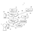
- the device management system 1 includes a control server 10, a user terminal 20, a management device 30, and a management target device 40. Although a plurality of management target devices 40 are illustrated in FIG. 1, one management target device 40 may be connected to one management device 30.
- Each management range T includes a management device 30, one or more managed devices 40, and one or more user terminals 20.
- the management range T indicates the range of the management target device 40 that is managed by the management apparatus 30.
- the management range T corresponds to, for example, a building where the management device 30 is installed, but is not limited thereto.
- the management device 30 is a device that manages (monitors and controls) the management target device 40 existing in the management range T in which the management device 30 is installed.
- the control server 10 is a device that performs user registration of a user who uses the management device 30 installed in each management range T and management (monitoring and control) of the management device 30.
- the user terminal 20 is a terminal used by a user who uses the management device 30, and monitors and controls the management device 30 and the management target device 40 by directly communicating with the management device 30 using short-range wireless communication. It plays a role as a user IF (Interface). Further, the user terminal 20 can communicate with the control server 10 as necessary, for example, when communication using the short-range wireless communication with the management apparatus 30 is not possible. The user terminal 20 can also communicate with the management apparatus 30 using a wireless LAN.
- the device management system 1 shown in FIG. 2 further includes an IoT (Internet of Things) device 50 and an IoT server 60.
- IoT Internet of Things
- the management device 30, the management target device 40, and the IoT device 50 are assumed to be installed at the home of the user U (hereinafter simply referred to as “user home”).
- the user's home corresponds to one management range T in FIG.
- the user terminal 20 is, for example, a portable portable terminal operated by the user U.
- the control server 10, the user terminal 20, the management device 30, and the management target device 40 can communicate with each other via the communication network N1 and the communication network N2.
- the IoT device 50 and the IoT server 60 can communicate with each other via the communication network N1 and the communication network N2. Further, the control server 10 and the IoT server 60 can communicate with each other via the communication network N1.
- the user terminal 20 can perform direct short-range wireless communication with the management apparatus 30 through, for example, Bluetooth (registered trademark) without using the communication network N1 and the communication network N2.
- Bluetooth registered trademark
- the management device 30 manages the management target devices 40 such as various home appliances installed in the user's home.
- the management target device 40 may be any device.
- an air conditioner an electric water heater, a household solar power generation system, a fuel cell ( Examples include fuel cells, storage batteries, electric vehicle charger-dischargers, lighting devices, smart meters, and the like.
- the management apparatus 30 collects “information regarding the operation state of the management target device 40” from the management target device 40 and transmits it to the control server 10.
- the management device 30 provides information on the environment in the user's home (hereinafter referred to as “environment information”), such as temperature, humidity, illuminance, amount of floating dust (floating dust), TVOC amount (total volatile organic compound, Total Volatile Organic Compounds), a plurality of sensors that measure the CO2 concentration, the atmospheric pressure, and the like, and environment information measured by these sensors is transmitted to the control server 10.
- environment information information including both or at least one of environment information and “information regarding the operation state of the management target device 40” is referred to as “management information”.
- the control server 10 collects environmental information related to each user's home from each management device 30 installed in a plurality of different user homes, and information related to the operating state of the management target device 40 installed in each user home, Accumulate the collected information (management information) in the database.
- the control server 10 also has a function of registering a user U who has installed the management device 30 at home, and a function of statistically analyzing the accumulated management information.
- a management application (hereinafter referred to as “management application”) for displaying management information and monitoring and controlling the management target device 40 is installed in the user terminal 20.
- Various settings for the control server 10 and the management device 30 can be performed by executing the application.
- the management device 30 does not have any operation buttons other than those for activation / reset. Display of information related to the operation state of the management target device 40, reception of control performed on the management target device 40, and the like are performed on the user terminal 20 side.
- the user terminal 20 can be realized by, for example, a mobile phone called a so-called smartphone, a tablet-type terminal, a PDA (Personal Digital Assistant), or the like.
- connection settings for example, SSID and password settings
- connection settings for example, SSID and password settings
- a user terminal 20 that is a mobile phone performs communication settings for connecting to a wireless LAN or a wired LAN or performing user registration to the management apparatus 30.
- the communication network N1 is the Internet composed of a wired network and a wireless network, and can include a public wireless LAN access point, a mobile phone base station, and the like.
- the communication network N2 is a communication network in a user's home composed of a wired network and a wireless network, and can include a wireless LAN access point, a LAN switch, and the like.
- the communication path when the user terminal 20 and the management apparatus 30 communicate via short-range wireless is referred to as a communication path R1 (first communication path).
- a communication path when the control server 10 and the management apparatus 30 communicate via the communication network N1 and the communication network N2 is referred to as a communication path R2 (second communication path).
- a communication path when the management apparatus 30 and the management target device 40 communicate via the communication network N2 is referred to as a communication path R3 (third communication path).
- a communication path when the user terminal 20 and the control server 10 communicate is referred to as a communication path R4 (fourth communication path). More specifically, a communication path when communicating via the communication network N1 and the communication network N2 is referred to as a communication path R4a, and a communication path when communicating via the communication network N1 is referred to as a communication path R4b. That is, the communication route R4a is a communication route that is used when the user terminal 20 is in the user's home and is not performing short-range wireless communication with the management device 30, and the communication route R4b is the user This is a communication path used when the terminal 20 is outside the user's home (that is, when connected to a mobile communication network such as LTE (Long Term Evolution)).
- LTE Long Term Evolution
- a communication path when the IoT device 50 and the IoT server 60 communicate via the communication network N1 and the communication network N2 is referred to as a communication path R5.
- a communication path when the IoT server 60 and the control server 10 communicate via the communication network N1 is referred to as a communication path R6.
- a communication path when the user terminal 20 and the management apparatus 30 communicate via the communication network N2 is referred to as a communication path R7.
- the management device 30 can be monitored and controlled without performing a procedure of individually registering the management target device 40 to be monitored in the management device 30 so that the management target device 40 can be easily managed. You may make it communicate with the management object apparatus 40 using a protocol. As an example of such a protocol, for example, a protocol called ECHONET Lite (registered trademark) may be used. In the following description, it is assumed that the management device 30 monitors and controls the management target device 40 using ECHONET Lite (registered trademark), but this embodiment is intended to be limited to this. It is not. Any protocol may be used between the management apparatus 30 and the management target device 40.
- the IoT device 50 is a device for third party (3 rd Party) to utilize the service provided.
- the IoT server 60 is a server provided by the third party, and the IoT device 50 provides a service to the user in cooperation with the IoT server 60.
- the IoT device 50 may be any device, and examples thereof include an AI (Artificial Intelligence) speaker that responds to a user's inquiry by voice or the like.
- the IoT server 60 provides an external cooperation API (Application Programmable Interface) capable of operating an external device using the IoT device 50, and the control server 10 uses the API to In response to the user's inquiry input to the IoT device 50, the management information content is made to respond from the IoT device 50.
- the user is provided with a function capable of operating the management target device 40 by voice.
- FIG. 3 is a diagram illustrating an appearance of the management device 30.
- the management device 30 includes a housing 301, an LED indicator 302, a display device 350, an optical sensor 363, and a dust sensor 364. Sensors other than the optical sensor 363 and the dust sensor 364 are stored in the housing 301.
- the LED indicator 302 mainly notifies the user of the operation state of the main body of the management apparatus 30 such as the power supply state and the operation status of each sensor.
- a plurality of LEDs are arranged in the display device 350, and the display device 350 realizes a display function as a whole by switching on / off of the plurality of LEDs.
- the display device 350 can display the time and weather, the state of the user's home, and the like with icons and characters.
- the optical sensor 363 is attached obliquely to the upper surface of the housing 301 (the surface where the display device 350 exists). Since the management device 30 can be installed not only on the floor but also on a wall, the optical sensor 363 is attached obliquely, so that the measurement result of the illuminance in the user's home is greatly increased by the installation method of the management device 30. The change is suppressed.
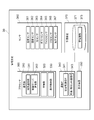
- the management device 30 includes a processor 300, a communication IF (Interface) 340, a display device 350, a sensor 360, and a storage device 370.
- a communication IF Interface
- the processor 300 is a device for integrally controlling each function in the management device 30 such as a CPU (Central Processing Unit).
- the communication IF 340 can include, for example, a near field communication IF 341 that communicates with the user terminal 20 by near field communication such as Bluetooth, and a wired / wireless LAN communication IF 343 that is an interface connected to the communication network N2.
- the near field communication IF 341 is a communication interface for connecting to the user terminal 20 by near field wireless such as Bluetooth.
- the short-range communication IF 341 transmits, for example, identification information assigned to the management device 30 to a surrounding device as a beacon signal when activated.
- the wired / wireless LAN communication IF 343 is a communication interface for connecting to the communication network N2. Specifically, the wired / wireless LAN communication IF 343 has a function of connecting to a wireless LAN and a function of connecting to Ethernet (Ethernet) that is a wired LAN.
- Ethernet Ethernet
- the sensor 360 includes various sensors for the management device 30 to measure the user's home.
- the sensor 360 includes a temperature sensor 361, a humidity sensor 362, an optical sensor 363, a dust sensor 364, a TVOC sensor 365, a CO2 sensor 366, and an atmospheric pressure sensor 367.
- the sensors included in the sensor 360 are not limited to these, and may include other sensors for measuring the user's home.
- Various numerical values detected by the sensor 360 are stored in the management apparatus 30 and transmitted to the control server 10 as environmental information of a place (user's home) where the management apparatus 30 is installed.
- the temperature sensor 361 measures the temperature of the room where the management device 30 is installed.
- the humidity sensor 362 measures the humidity in the room where the management device 30 is installed.
- the optical sensor 363 measures the illuminance in the room where the management device 30 is installed.
- the dust sensor 364 measures the amount of dust floating in the room where the management device 30 is installed.
- the TVOC sensor 365 measures the amount of total volatile organic compounds such as formaldehyde present in the room where the management device 30 is installed.
- the CO2 sensor 366 measures the content rate of oxygen dioxide in the room where the management device 30 is installed.
- the atmospheric pressure sensor 367 measures the atmospheric pressure in the room where the management device 30 is installed.
- the storage device 370 includes a memory and an SSD (Solid State Drive) or an eMMC (embedded Multi Media Card), and stores management information 373 managed by the management device 30.
- the management information 373 includes information related to the operation state of the management target device 40 collected by the management device 30, environmental information collected by the sensor 360 and where the management device 30 is installed (in the user's home), and Or at least one of them.
- the processor 300 implements each function included in the communication unit 310, the management unit 320, and the display control unit 330 by executing a program stored in the storage device 370.
- the program can be stored in a storage medium.
- the storage medium storing the program may be a computer-readable non-transitory storage medium (Non-transitory computer readable medium).
- the non-transitory storage medium is not particularly limited, but may be a storage medium such as a USB memory or a CD-ROM.
- the DB 371 can be realized by using the storage device 370.
- the communication unit 310 includes a terminal communication unit 311 and a control server communication unit 313.
- the terminal communication unit 311 performs a process of establishing a communication path (communication path R1) between the user terminal 20 and the management apparatus 30, and a process of transmitting and receiving data using the established communication path.
- the terminal communication unit 311 transmits identification information assigned to the management device 30 itself to the user terminal 20 and receives a connection request from the user terminal 20 that has received the identification information, whereby the terminal communication unit 311 manages the user terminal 20.
- a wireless connection is established with the device 30 via the communication path R1.
- the identification information assigned to the management device 30 itself may be an ID (for example, a MAC address) for uniquely identifying the user terminal 20 used in short-range wireless communication such as Bluetooth.
- the terminal communication unit 311 may be referred to as a “connection unit” or a “connection unit”.
- the control server communication unit 313 performs a process of establishing a communication path (communication path R2) between the control server 10 and the management apparatus 30, and a process of transmitting and receiving data using the established communication path.
- the control server communication unit 313 performs communication settings for performing communication with the control server 10 via the communication path R2 in response to an instruction from the user terminal 20 via the wireless connection via the communication path R1.
- the communication setting is, for example, connection setting to a wireless LAN access point or a wired LAN included in the communication network N2.
- the control server communication unit 313 may be referred to as “setting unit” or “setting unit”.
- the management unit 320 collects the operation state of the management target device 40 through the communication path R3. In addition, the management unit 320 collects environmental information detected by the sensor 360. The management unit 320 transmits management information 373 including the operating state and / or environment information of the management target device 40 to the control server 10 via the control server communication unit 313 via the communication path R2. When receiving a request from the user terminal 20, the management information 373 including the operation state and / or environment information of the management target device 40 is transmitted to the user terminal 20 through the communication path R1. In addition, the management unit 320 manages the control target device specified by the user terminal 20 with control information (control message) for controlling each of the management target devices 40 based on an instruction from the user terminal 20 or the control server 10. 40 through the communication path R3. The management unit 320 supports ECHONET Lite (registered trademark), and uses ECHONET Lite (registered trademark) to collect the operation state of the management target device 40 and transmit control information.
- ECHONET Lite registered trademark
- ECHONET Lite registered trademark
- the management unit 320 determines whether it is necessary to control the management target device 40 based on the environmental information collected from the sensor 360, and determines that it is necessary to control the management target device 40.
- the control information may be transmitted to the management target device 40 via the communication path R3. For example, when the management unit 320 detects that the room temperature measured by the temperature sensor 361 is equal to or higher than a predetermined threshold, the management unit 320 controls the cooling target device 40 that is an air conditioner to turn on the cooling. May be.
- the management device 30 communicates with the control server 10 when the communication setting for the control server communication unit 313 to communicate with the control server 10 via the communication path R2 is completed. It becomes possible. Therefore, the management unit 320 may start processing for transmitting the management information 373 to the control server 10 after the communication setting for performing communication between the management device 30 and the control server 10 is completed.
- the display control unit 330 controls the content of the screen displayed on the display of the user terminal 20 communicating via the communication path R1, the content of the icon displayed on the display device 350, and the like.
- FIG. 5 is a functional block diagram illustrating a specific example of a functional configuration of the control server 10.
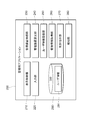
- the control server 10 includes a management device control unit 110, a user registration unit 120, a user terminal control unit 130, an IoT device cooperation unit 140, and a database (DB) 150.
- the database (DB) 150 stores user information 151 and management information 153.
- the management device control unit 110 controls the management device 30 by communicating with the management device 30 using the communication path R2.
- the management device control unit 110 includes a control instruction unit 111 and a management information management unit 113.
- the control instruction unit 111 instructs the management apparatus 30 to control the management target device 40.
- the control instruction unit 111 may instruct to control the management target device 40 based on an instruction from the user terminal 20 received by a control instruction receiving unit 135 described later.
- the control instruction unit 111 automatically determines whether it is necessary to control the management target device 40 based on the environment information included in the management information 153 acquired from the management device 30, and controls the management target device 40. If it is determined that it is necessary to do so, the management target device 40 may be instructed to be controlled. For example, when the control instruction unit 111 detects that the room temperature of the room included in the environment information is equal to or higher than a predetermined threshold, the management apparatus 30 turns on the cooling for the management target device 40 that is an air conditioner. You may make it instruct
- the management information management unit 113 acquires the management information 153 from the management device 30 and stores the acquired management information 153 in the DB 150.
- the management information 153 received by the management information management unit 113 includes information regarding the operating state of the management target device 40 and environmental information of the location where the management device 30 is installed.
- the management information management unit 113 analyzes the management information 153 stored in the DB 150, generates information to be notified to the user U as necessary, and passes it to the state notification unit 133.
- the analysis performed by the analysis unit 115 not only analyzes the management information 153 at the present time, but also statistically analyzes changes from the past to the present in the management information 153 collected from one management device 30, and controls This includes cross-sectional analysis of management information 153 collected from a plurality of management devices 30 connected to the server 10.
- the information to be notified to the user U is, for example, an analysis result that the usage amount of the air conditioner that is the management target device 40 is significantly larger than the usage amount of the previous year at the user U's home, or the management target device 40. An analysis result or the like that the usage amount of the air conditioner is significantly larger than the average of other users may be used.
- the user registration unit 120 registers the user information 151 including the identification information of the management apparatus 30 and the information for identifying the user U received by the user information acquisition unit 131 described later from the user terminal 20 in the DB 150. That is, in the DB 150, information for identifying the user U who performs user registration for using the management device 30 at home and the identification information of the management device 30 installed at the home by the user U are registered in association with each other.
- the DB 150 information for identifying the user U who performs user registration for using the management device 30 at home and the identification information of the management device 30 installed at the home by the user U are registered in association with each other.
- the DB 150 stores a list in which identification information of all management devices 30 that have been manufactured or shipped is recorded.
- the user registration unit 120 may confirm whether or not the identification information of the management device 30 received from the user terminal 20 is included in the list before registering the user information 151 in the DB 150. If the identification information of the management device 30 received from the user terminal 20 is not included in the list, it may be regarded as an unauthorized management device 30 and registration of the user information 151 may be rejected.
- the user terminal control unit 130 controls the user terminal 20 by communicating with the user terminal 20.
- the user terminal control unit 130 includes a user information acquisition unit 131, a status notification unit 133, and a control instruction reception unit 135.
- the user information acquisition unit 131 receives the user information 151 from the user terminal 20 via the communication path R4a or the communication path R4b, and passes the received user information 151 to the user registration unit 120.
- the user information 151 received from the user terminal 20 includes identification information of the management device 30 and information for identifying the user U.
- the user information 151 may further include an IP address (IP address of the management device 30) for communicating with the management device 30 and the like.
- the user information 151 may include identification information assigned to the user terminal 20.
- the status notification unit 133 notifies the management information 153 received by the management information management unit 113 to the user terminal 20 through the communication path Ra, the communication path R4b, or the communication path R2.
- the timing at which the state notification unit 133 notifies the user terminal 20 of the management information 153 may be a timing at which a request from the user terminal 20 operated by the user U is received, for example.
- the status notification unit 133 may notify the user terminal 20 of information to be notified to the user, which is obtained by analyzing the management information 153 by the management information management unit 113.
- the control instruction receiving unit 135 receives an instruction regarding control of the management target device 40 from the user terminal 20 and notifies the control instruction unit 111 of the content of the received control.
- the management target device 40 is an air conditioner
- the control instruction receiving unit 135 notifies the control instruction unit 111 of the instruction, and the control instruction unit 111 turns on / off the switch of the management target device 40 that is an air conditioner with respect to the management device 30. Instruct to turn off.
- the IoT device cooperation unit 140 includes an instruction reception unit 141 and a management information notification unit 143.
- the instruction receiving unit 141 receives from the IoT server 60 an instruction regarding control of the management target device 40 input to the IoT device 50.
- the IoT device cooperation unit 140 notifies the control instruction unit 111 of the content of the received control.
- the control instruction unit 111 instructs the management apparatus 30 to control the management target device 40.
- the management information notification unit 143 notifies the IoT device 50 of the management information 153 stored in the DB 150 via the IoT server 60.
- the timing at which the management information notification unit 143 notifies the management information 153 may be, for example, when a management information inquiry is received from the IoT device 50 via the IoT server 60.
- the management application 200 includes a display control unit 210, an input unit 220, a management device connection unit 230, a management device setting unit 240, a user information registration unit 250, a management information acquisition unit 260, a control instruction unit 270, a notification unit 280, and a database ( DB) 290.
- the DB 290 stores user information 291 in a storage area managed by the management application 200.
- the display control unit 210 controls display on the display of the user terminal 20.
- the display control unit 210 causes the display to display various settings for the management device 30 and various settings for the control server 10.
- the display control unit 210 can also display management information received from the control server 10 or the management apparatus 30 and including management information including information related to the operating state of the management target device 40 and environmental information measured by the management apparatus 30.
- the display control unit 210 displays the information on the display.
- the display control unit 210 may display a display screen configuring a GUI (Graphical User Interface) for controlling the management apparatus 30 and the management target device 40 on the display.
- GUI Graphic User Interface
- the input unit 220 receives an input operation from the user U to, for example, an operation button or a touch panel provided on the user terminal 20, and transmits the operation content to the related functional block. For example, when a communication setting for the management device 30 to communicate with the control server 10 or an operation input for user registration is made, the input unit 220 notifies the management device setting unit 240 and the control instruction unit 270 to that effect. introduce.
- the management device connection unit 230 performs short-distance wireless connection with the management device 30 using, for example, Bluetooth. More specifically, if the user U receives an identification information (for example, UUID) transmitted by the management device 30 and an operation input indicating that the connection with the identification information may be performed, the management device connection unit 230 establishes a wireless connection with the management apparatus 30. Thereafter, for example, communication and various settings performed by the management device setting unit 240 to the management device 30 are performed via the wireless connection.
- an identification information for example, UUID
- the management device setting unit 240 performs various settings necessary for the operation of the management device 30 in response to an operation input from the user U to the input unit 220.
- the management apparatus setting unit 240 performs connection setting to the wireless access point for the management apparatus 30 to connect to the communication network N ⁇ b> 2 with respect to the management apparatus 30.
- short-distance wireless communication such as Bluetooth established by the management device connection unit 230 can be used for various settings performed by the management device setting unit 240 on the management device 30.
- the user information registration unit 250 performs registration processing of the user information 291 in response to an operation input from the user U to the input unit 220. More specifically, when an input of a user ID (for example, an e-mail address) and a password, which are account information relating to a service provided by the SNS or third party of the user U, is received from the input unit 220, the user information registration unit 250 The SNS server (not shown) or the IoT server 60 is accessed via N2, and the validity of the account information is confirmed. When the validity of the account information is confirmed, the user information registration unit 250 uses the communication path R4a to obtain information for identifying the user U and identification information for the management device 30 acquired by the management device connection unit 230. The user information 291 is transmitted to the control server 10.
- a user ID for example, an e-mail address
- a password which are account information relating to a service provided by the SNS or third party of the user U
- the user information 291 is registered in the DB 290.
- the information for identifying the user U may specifically be a user ID (for example, an e-mail address) related to a service provided by the SNS of the user U or a third party.
- the management application 200 confirms the validity of the account information on the SNS included in the user information 291, and thus the management application 200, for example, the screen capture image of the user terminal 20. It is also possible to perform processing such as posting to SNS.
- the management information acquisition unit 260 acquires management information from the management device 30 using the communication path R1 when short-range wireless communication is established with the management device 30. Moreover, the management information acquisition part 260 acquires management information from the control server 10 using communication path R4a or communication path R4b, when short-distance wireless communication with the management apparatus 30 is not established.
- the control instruction unit 270 receives a control instruction for the management target device 40 from the user U, and manages the content of the received control using the communication path R1 when short-range wireless communication is established with the management apparatus 30. Notify device 30. If short-distance wireless communication has not been established with the management apparatus 30, the control instruction unit 270 notifies the control server 10 of the content of the received control using the communication path R4a or the communication path R4b.
- the notification unit 280 notifies the user U of information to be notified to the user in response to a request from the control server 10. For example, the user U is notified of information that the usage amount of the air conditioner that is the management target device 40 is significantly larger than the previous year's usage amount for the user or that the usage amount is significantly higher than the average of other users. By receiving such notification, the user U can take measures such as frequently turning off the air conditioner switch.
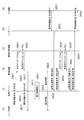
- FIG. 7 is a sequence diagram showing a processing flow (part 1) of the device management system 1 according to the present embodiment.
- FIG. 7 shows a processing procedure from when the management apparatus 30 is activated until management information is collected and notified to the control server 10.
- Each processing step to be described later can be executed in any order or in parallel as long as there is no contradiction in processing contents, and other steps can be added between the processing steps. good. Further, a step described as a single step for convenience can be executed by being divided into a plurality of steps, and a step described as being divided into a plurality of steps for convenience can be executed as one step.
- the management apparatus 30 When the management apparatus 30 is activated, for example, when the management apparatus 30 is connected to a power source or the activation button of the management apparatus 30 is pressed, the management apparatus 30 transmits a beacon signal including identification information (UUID) of the own apparatus. Transmission is started (S701).
- the management application 200 of the user terminal 20 receives the beacon signal, the identification information included in the received beacon signal is displayed on the display, so that the user U can select a device to be connected for Bluetooth (registered trademark) communication. Prompt.
- the management application 200 Upon receiving an input from the user U as the device to be connected on the screen (S703), the management application 200 performs a pairing process for establishing a wireless connection with the management device 30 (S705). ).
- the management application 200 displays a display screen that prompts the management device 30 to input information to be set on the display.
- the management application 200 receives input of account information (user ID (for example, email address) and password) related to a service provided by the user SNS or a third party by the user U (S707).
- the management application 200 authenticates the user U by inquiring the SNS server or the IoT server 60 about the validity of the received account information (S709).
- the management application 200 identifies the identification information of the management device 30 and the information identifying the user U (related to the SNS or third party service) input as the connection target in S703.
- User information 291 including a user ID (for example, mail address) is registered in the control server 10 (S711).
- the control server 10 registers the information identifying the user U received from the user terminal 20 and the identification information of the management device 30 in the DB 150 as the user information 151 (S713). If the registration is completed, the control server 10 notifies the user terminal 20 to that effect (S715).
- the management application 200 receives input of setting information for the management device 30 to connect to the wired LAN or the wireless LAN from the user U (S717). Using the setting information, the management application 200 performs settings for connecting to the wired LAN or the wireless LAN via the Bluetooth communication with the management apparatus 30 (S719).
- the settings for connecting to a wired LAN or a wireless LAN include, for example, SSID selection, encryption key input, management device 30 IP address setting, DHCP usage setting, and the like.
- the management apparatus 30 can access the Internet.
- the URL of the control server 10 is set in advance in the management device 30, and the management device 30 can start communication with the control server 10 by accessing the URL.
- control server 10 transmits account information (ID and password) for connecting to the IoT server 60 to the IoT server 60 (S725).
- account information ID and password
- the IoT server 60 confirms that the account information exists, the IoT server 60 notifies the control server 10 that the authentication is successful, and the IoT server 60 provides the control server 10 with the authentication information.
- the use of the external cooperation API is permitted (S727).
- the management device 30 collects environmental information by performing measurement in the home where the management device 30 is installed using each sensor 360 provided in the management device 30 (S731).
- the management device 30 may collect environment information in a predetermined cycle and store the management information 373 including the collected environment information in the storage device 370 in time series.
- the management device 30 transmits a status request message to the communication network N2 in order to search for the management target device 40 connected to the communication network N2 (S733).
- the status request message is obtained by specifying a multicast address defined in the specification as a destination address in a Get message (property value read request) defined in the specification of ECHONET Lite (registered trademark).
- the status request message is broadcast to all the management target devices 40 connected to the communication network N2.
- Each managed device 40 that has received the status request message transmits a response message to the management apparatus 30 (S735).
- the status response message is, for example, a Get_Res message (property value read response) defined in the specification of ECHONET Lite (registered trademark).
- the status response message includes information (class) indicating the type of the management target device 40 in addition to the operation state (property) of the management target device 40, and the management device 30 manages the management target based on the information. It is possible to identify whether the device 40 is an air conditioner, a lighting device, or a smart meter.
- the management apparatus 30 stores the management target device 40 that has received the response message as a management target device 40 to be managed.
- the management target device 40 can spontaneously transmit a notification message indicating its own operation state (property) to the management device 30 (S737).
- the notification message is, for example, an INF message (property value notification) defined in the specification of ECHONET Lite (registered trademark).
- the management target device 40 can transmit a notification message to the management device 30 when its operation state changes.
- the case where the own operation state has changed is, for example, a case where the user adjusts the temperature setting of the management target device 40 which is an air conditioner using a direct remote controller.
- the management target device 40 sends a notification message by itself. It transmits to the management apparatus 30.
- the notification message is appropriately transmitted from the management target device 40 to the management device 30 as necessary.
- the management device 30 transmits the management information including the environment information collected in S731 and the operation state of the managed device 40 collected in S735 or S737 to the control server 10 (S739).
- the processing procedure of S739 is appropriately performed when the management apparatus 30 detects a change in the environmental information or the operating state of the management target device 40.
- FIG. 8 is a sequence diagram showing a process flow (part 2) of the device management system 1 according to the present embodiment.
- FIG. 8 shows a processing procedure when the management information is displayed on the screen of the user terminal 20 and a processing procedure when the management target device 40 is controlled from the user terminal 20 or the IoT device 50.
- the user U selects display of management information on the screen of the management application 200, or the user U selects an operation on a predetermined management target device 40 on the screen of the management application 200.
- the user terminal 20 and the management device 30 have established short-range wireless communication
- the user terminal 20 transmits a management information request message / control request message to the management device 30 using the communication path R1 (S801).
- the user terminal 20 and the management apparatus 30 have not established near field communication, the user terminal 20 transmits a management information request message / control request message to the control server 10 using the communication path R4a or the communication path R4b. (S803).
- control server 10 transmits the management information request message / control request message received from the user terminal 20 to the management apparatus 30 using the communication path R2 (S805).
- the user terminal 20 and the management apparatus 30 have not established near field communication, the user terminal 20 transmits a management information request message / control request message to the management apparatus 30 using the communication path R7. May be.
- the management apparatus 30 executes the operation on the predetermined management target device 40 instructed by the user.
- a control message including the content of the control instructed by the user is transmitted to the management target device 40 (S807).
- the control message is, for example, a Set message (property value write request) defined in the specification of ECHONET Lite (registered trademark).
- Each managed device 40 that has received the control message transmits a control response message to the management apparatus 30 (S809).
- the control response message is, for example, a Set_Res message (property value write response) defined in the specification of ECHONET Lite (registered trademark).
- the control response message includes the control result, and the management device 30 can grasp the control result (for example, the switch of the device is turned on).
- the management device 30 transmits management information or a control result to the user terminal 20.
- the management device 30 transmits a management information response message / control response message to the control server 10 using the communication path R2 (S811). ).
- the control server 10 transmits the management information response message / control response message received from the management device 30 to the user terminal 20 using the communication path R4a or the communication path R4b (S813).
- the management apparatus 30 transmits a management information response message / control response message to the user terminal 20 using the communication path R1 (S815).
- the management device 30 transmits a management information response message / control response message to the user terminal 20 using the communication path R7. May be.
- the management information 373 stored in the management device 30 is transmitted to the user terminal 20.
- the processing procedures of S805 and S811 are omitted, and the management information 153 stored in the control server 10 is transmitted to the user terminal 20. You may do it.
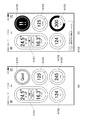
- FIG. 9 shows a screen display example of the management application 200.
- FIG. 9A is a display example of a state in which the indoor environment is determined to be good
- FIG. 9B shows that the amount of floating dust (floating dust) is large in the indoor environment and ventilation is required. It is a display example of a certain state.
- the display area A101 is notified of the indoor temperature measured by the temperature sensor 361, the operating state of the management target device 40 that is an air conditioner, on / off of cooling, and the management target device 40 that is an air conditioner.
- the outside air temperature and ON / OFF of the management target device 40 that is a humidifier are displayed.
- the display area A102 the illuminance in the room measured by the optical sensor 363 is displayed.
- the display area A103 the amount of indoor floating dust measured by the dust sensor 364 is displayed.
- the display area A104 the amount of indoor floating dust measured by the TVOC sensor 365 is displayed.
- a comprehensive evaluation result of the indoor environment is displayed.
- FIG. 9A the display area A101 is notified of the indoor temperature measured by the temperature sensor 361, the operating state of the management target device 40 that is an air conditioner, on / off of cooling, and the management target device 40 that is an air conditioner.
- the outside air temperature and ON / OFF of the management target device 40 that is a humidifier are displayed.
- the control server 10 When the user terminal 20 and the management device 30 have not established near field communication, the control server 10 notifies the user terminal 20 of information to be notified to the user U using the communication path R4a or the communication path R4b ( S823). Note that the control server 10 may notify the management apparatus 30 of information to be notified to the user U using the communication path R2 (S825). In this case, when the short-distance wireless communication is established between the user terminal 20 and the management apparatus 30, the management apparatus 30 transfers information to be notified to the user U to the user terminal 20 using the communication path R1. When short-range wireless communication has not been established, information to be notified to the user U may be transferred to the user terminal 20 using the communication path R7 (S827).
- the management unit 320 of the management device 30 generates information to be notified to the user U (such as information that is significantly larger than the usage amount of the user U last year) by statistically analyzing the management information 373.
- the user terminal 20 may be notified.
- the management apparatus 30 notifies the user terminal 20 of information to be notified to the user U using the communication path R7. It may be.
- the management apparatus 30 may notify the user terminal 20 of information to be notified to the user U using the communication path R1. .
- the user U requests the notification of management information by voice toward the IoT device, or requests the operation of the predetermined management target device 40 by voice.
- the IoT device 50 transmits a voice requesting management information or a voice requesting an operation of a predetermined management target device 40 to the IoT server 60 (S831).
- the IoT server 60 transmits a management information request message / control request message to the control server 10 using the external cooperation API (S833).
- the control server 10 transmits a management information request message / control request message using the communication path R2 (S835).
- the management apparatus 30 executes the operation on the predetermined management target device 40 instructed by the user.
- a control message including the content of control instructed by the user is transmitted (S837).
- Each managed device 40 that has received the control message transmits a control response message to the management apparatus 30 (S839).
- the processing procedures of S837 and S839 are the same as the processing procedures of S807 and S809, respectively, and the details are omitted.
- the management device 30 transmits management information or a control result to the IoT server 60 (S843).
- the IoT server 60 transmits audio data indicating management information or a control result to the IoT device 50, and the IoT device 50 outputs the audio data from the speaker (S845).
- the user terminal 20 may notify the control server 10 of the location information of the user terminal 20 in the processing procedure of S711 in FIG. Further, when storing the management information 153 in the DB 150, the control server 10 may store the notified position information in association with the management information 153. When analyzing the management information 153, the control server 10 may perform the analysis by regarding the position information as a place where the management device 30 is installed. Since the control server 10 can collect management information from a plurality of management devices 30 installed in a plurality of user homes, the control server 10 can statistically analyze the management information collected from the plurality of user homes. Thus, it is possible to perform analysis in consideration of the installation location of the management device 30.
- control server 10 includes a control unit 171, a communication interface (I / F) unit 175, a storage unit 177, a display unit 181, and an input unit 183, and each unit is a bus line 185. Connected through.
- I / F communication interface
- the control unit 171 includes a CPU (Central Processing Unit, not shown), a ROM (Read Only Memory, not shown), a RAM (Random Access Memory) 153, and the like.
- the control unit 171 is configured to execute the control program 179 stored in the storage unit 177 so that, in addition to the function as a general information processing apparatus, the processing related to the control server 10 described above can be realized.
- the management device control unit 110, the user registration unit 120, and the user terminal control unit 130 described with reference to FIG. 5 can be realized as a control program 179 that is temporarily stored in the RAM 173 and operates on the CPU. is there.
- the RAM 173 temporarily holds a part or all of the DB 150 storing the user information 151 and the management information 153 shown in FIG. 5 in addition to the code included in the control program 179. Further, the RAM 173 is used as a work area when the CPU executes various processes.
- the communication I / F unit 175 is a device for performing data communication with external devices including the user terminal 20 and the management device 30 via the communication network N1. Communication performed by the management device control unit 110, the user registration unit 120, and the user terminal control unit 130 shown in FIG. 5 between the user terminal 20, the management device 30, and the IoT server 60 are all communication I / F units 175. Do.
- the storage unit 177 is a nonvolatile storage medium (for example, a computer-readable non-transitory storage medium) such as an HDD (Hard Disk Drive) or a flash memory.
- the storage unit 177 stores an operating system (OS), applications, and data (not shown) for realizing a function as a general information processing apparatus.
- the storage unit 177 stores the control program 179 and the DB 150. As described above, the management apparatus control unit 110, the user registration unit 120, and the user terminal control unit 130 illustrated in FIG. 5 are included in the control program 179.
- DB 150 can include, for example, user information 151 and management information 153 shown in FIG.
- Various data included in the DB 150 is loaded into the RAM 173 as necessary, and is referred to by the CPU included in the control unit 171.
- the display unit 181 is a display device for displaying information to the administrator.
- Specific examples of the display unit 181 include a liquid crystal display and an organic EL (Electro-Luminescence) display.
- the input unit 183 is a device for receiving input from the administrator.
- Specific examples of the input unit 183 include a keyboard, a mouse, and a touch panel.
- control server 10 does not necessarily include the display unit 181 and the input unit 183.
- the display unit 181 and the input unit 183 may be connected to the control server 10 from the outside via various interfaces such as a USB (Universal Serial Bus) or a display port.
- USB Universal Serial Bus
- the control server 10 is not limited to the hardware configuration shown in FIG.
- the control server 10 may be realized using a cloud server or a virtual server.
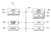
- the user terminal 20 includes a control unit 901, a short-range wireless communication unit 905, a wireless communication unit 907, a storage unit 909, a display unit 911, and an input unit 913. Connection is made via a bus line 915.
- the control unit 901 includes a CPU (not shown), a ROM (not shown), a RAM 903, and the like. By executing the management application 200 stored in the storage unit 909, the control unit 901 is configured to realize the processing according to the present embodiment in addition to the function as a general information processing apparatus.
- the unit 280 can be realized as a part of the management application 200 operating on the CPU after being temporarily stored in the RAM 903.
- the RAM 903 temporarily holds a part or all of the DB 290 storing the user information 291 shown in FIG. 6 in addition to the code included in the management application 200.
- the RAM 903 is also used as a work area when the CPU executes various processes.
- the short-range wireless communication unit 905 is a device for receiving a beacon signal by, for example, Bluetooth communication periodically transmitted from the management device 30 and communicating with the management device 30.
- the wireless communication unit 907 is a device for performing data communication with an external device including the control server 10 via the communication network N1 or the communication network N2.
- the storage unit 909 is a non-volatile storage medium (for example, a computer-readable non-transitory storage medium) such as an HDD or a flash memory.
- the storage unit 909 stores an operating system, applications, and data for realizing functions as a general information processing apparatus.
- the storage unit 909 stores the management application 200.
- the management application 200 includes a display control unit 210, an input unit 220, a management device connection unit 230, a management device setting unit 240, a user information registration unit 250, a management information acquisition unit 260, a control instruction unit 270, and a notification unit 280. included.
- the storage unit 909 also has a storage area for storing the DB 290 managed by the management application 200.
- the DB 290 includes user information 291 as described with reference to FIG. Various data included in the DB 290 is loaded into the RAM 903 as necessary, and is referred to by the CPU included in the control unit 901.
- the display unit 911 is a display device for displaying information notified to the user U.
- Specific examples of the display unit 911 include a liquid crystal display and an organic EL display.
- the input unit 913 is a device for receiving input from the user U.
- Specific examples of the input unit 913 include a touch panel and various operation buttons.
- the display unit 911 and the input unit 913 can be realized as an external device or the like with which the short-range wireless communication unit 905 can communicate, for example.
- the management device 30 can acquire environmental information such as the temperature of the room of the user U in which the management device 30 is installed, and is installed in the user U's room. It is possible to collect and control the operation state of the management target device 40 such as a home appliance.
- the reference of the environment information and the operation state of the management target device 40 and the user interface for controlling the management target device 40 are provided on the user terminal 20 that the user U is familiar with. That is, since it is not necessary to provide an input interface such as an operation button on the management device 30, the user U can suitably perform an operation input.
- the management device 30 since the management device 30 collectively transmits information about the operation state of the management target device 40 such as a home appliance installed in the room of the user U to the control server 10, the control server 10 operates the operation of the management target device 40. Compared with the method of collecting information on the state individually, the processing load on the control server 10 can be suppressed.
- the information to be notified to the user U is generated by analyzing the management information including the environmental information and the operation state of the management target device 40, the information is notified from the user terminal 20 carried by the user U. Thereby, even if the user U is not in the vicinity of the management device 30, the user U can grasp information related to the user U's home.
Landscapes
- Engineering & Computer Science (AREA)
- Theoretical Computer Science (AREA)
- Physics & Mathematics (AREA)
- General Engineering & Computer Science (AREA)
- General Physics & Mathematics (AREA)
- Signal Processing (AREA)
- Telephonic Communication Services (AREA)
- Computer And Data Communications (AREA)
Abstract
L'invention concerne un système de gestion d'appareil (1), un dispositif de gestion (30) comprenant : un moyen de connexion (311) qui transmet des informations d'identification attribuées au dispositif de gestion, permettant ainsi une connexion sans fil à un terminal portable (20) actionné par un utilisateur ; un moyen de réglage (313) qui effectue, conformément à une instruction envoyée par le terminal portable par l'intermédiaire de la connexion sans fil, des paramètres de communication pour communiquer avec un serveur de commande (10); et un moyen de gestion (320) qui collecte l'état de fonctionnement d'un ou de plusieurs appareils à gérer, et transmet, au serveur de commande, des informations de gestion comprenant l'état de fonctionnement collecté d'un ou de plusieurs appareils à gérer. Le serveur de commande comprend : un moyen d'enregistrement (120) qui enregistre des informations d'utilisateur comprenant les informations d'identification du dispositif de gestion, lesdites informations d'identification ayant été reçues en provenance du terminal portable ; et un moyen de stockage (150) qui stocke les informations de gestion reçues en provenance du dispositif de gestion.
Applications Claiming Priority (2)
| Application Number | Priority Date | Filing Date | Title |
|---|---|---|---|
| JP2018079387A JP2019185677A (ja) | 2018-04-17 | 2018-04-17 | 機器管理システム、管理装置、管理方法及びアプリケーションプログラム |
| JP2018-079387 | 2018-04-17 |
Publications (1)
| Publication Number | Publication Date |
|---|---|
| WO2019203264A1 true WO2019203264A1 (fr) | 2019-10-24 |
Family
ID=68238954
Family Applications (1)
| Application Number | Title | Priority Date | Filing Date |
|---|---|---|---|
| PCT/JP2019/016450 Ceased WO2019203264A1 (fr) | 2018-04-17 | 2019-04-17 | Système de gestion d'appareil, dispositif de gestion, procédé de gestion, et programme d'application |
Country Status (2)
| Country | Link |
|---|---|
| JP (1) | JP2019185677A (fr) |
| WO (1) | WO2019203264A1 (fr) |
Cited By (2)
| Publication number | Priority date | Publication date | Assignee | Title |
|---|---|---|---|---|
| CN116888945A (zh) * | 2021-03-02 | 2023-10-13 | 大金工业株式会社 | 信息处理装置、信息处理方法、程序及信息处理系统 |
| US20240106896A1 (en) * | 2022-09-23 | 2024-03-28 | T-Mobile Innovations Llc | Iot device one tap activation |
Families Citing this family (3)
| Publication number | Priority date | Publication date | Assignee | Title |
|---|---|---|---|---|
| CN111764688A (zh) * | 2020-06-09 | 2020-10-13 | 南京景玉信息科技有限公司 | 一种基于升降设计的智能房屋收纳方法及其系统 |
| JP7324468B2 (ja) * | 2021-05-31 | 2023-08-10 | 独立行政法人国立病院機構 | 評価システム、オゾン発生器、加湿器、電子看板システム、及び情報提供システム |
| JP2023088763A (ja) * | 2021-12-15 | 2023-06-27 | パナソニックIpマネジメント株式会社 | 制御装置、機器 |
Citations (3)
| Publication number | Priority date | Publication date | Assignee | Title |
|---|---|---|---|---|
| JP2002238081A (ja) * | 2001-02-09 | 2002-08-23 | Mitsubishi Electric Corp | 電化製品の制御システム及びその制御方法 |
| JP2006129184A (ja) * | 2004-10-29 | 2006-05-18 | Toshiba Corp | ネットワーク家電制御システム |
| JP2015082782A (ja) * | 2013-10-23 | 2015-04-27 | 三菱電機株式会社 | 機器制御システム |
Family Cites Families (1)
| Publication number | Priority date | Publication date | Assignee | Title |
|---|---|---|---|---|
| JP6275756B2 (ja) * | 2016-01-18 | 2018-02-07 | デルタ電子株式会社 | 植物栽培システム、植物栽培装置、アプリケーションプログラム、及び植物栽培制御方法 |
-
2018
- 2018-04-17 JP JP2018079387A patent/JP2019185677A/ja active Pending
-
2019
- 2019-04-17 WO PCT/JP2019/016450 patent/WO2019203264A1/fr not_active Ceased
Patent Citations (3)
| Publication number | Priority date | Publication date | Assignee | Title |
|---|---|---|---|---|
| JP2002238081A (ja) * | 2001-02-09 | 2002-08-23 | Mitsubishi Electric Corp | 電化製品の制御システム及びその制御方法 |
| JP2006129184A (ja) * | 2004-10-29 | 2006-05-18 | Toshiba Corp | ネットワーク家電制御システム |
| JP2015082782A (ja) * | 2013-10-23 | 2015-04-27 | 三菱電機株式会社 | 機器制御システム |
Cited By (3)
| Publication number | Priority date | Publication date | Assignee | Title |
|---|---|---|---|---|
| CN116888945A (zh) * | 2021-03-02 | 2023-10-13 | 大金工业株式会社 | 信息处理装置、信息处理方法、程序及信息处理系统 |
| US20240106896A1 (en) * | 2022-09-23 | 2024-03-28 | T-Mobile Innovations Llc | Iot device one tap activation |
| US12244669B2 (en) * | 2022-09-23 | 2025-03-04 | T-Mobile Innovations Llc | IoT device one tap activation |
Also Published As
| Publication number | Publication date |
|---|---|
| JP2019185677A (ja) | 2019-10-24 |
Similar Documents
| Publication | Publication Date | Title |
|---|---|---|
| WO2019203264A1 (fr) | Système de gestion d'appareil, dispositif de gestion, procédé de gestion, et programme d'application | |
| RU2697642C1 (ru) | ЭФФЕКТИВНЫЙ СЕТЕВОЙ УРОВЕНЬ ДЛЯ ПРОТОКОЛА IPv6 | |
| US10156377B2 (en) | Distributed heating, ventilation, and air conditioning system with concurrent network connections | |
| US9646489B2 (en) | Remote control method and apparatus for home appliances | |
| CN104714412B (zh) | 对家用电器进行管理的方法、系统和移动终端 | |
| JP6197372B2 (ja) | 情報処理装置、情報処理方法及び情報処理プログラム | |
| KR101795025B1 (ko) | 네트워크 시스템 및 그 제어방법 | |
| TW201419797A (zh) | 智慧閘道、智慧家居系統及家電設備的智慧控制方法 | |
| CN110223495A (zh) | 用于在家庭网络系统中远程控制家庭设备的方法和设备 | |
| CN102736526A (zh) | 控制装置、控制方法、程序和系统 | |
| CN204926478U (zh) | 控制装置、控制系统 | |
| JP2015231226A5 (fr) | ||
| JP2018048774A (ja) | 情報提供システム、情報提供方法及び制御プログラム | |
| JP2014095685A (ja) | 配信装置、配信方法及び配信プログラム | |
| WO2017037327A1 (fr) | Accès à distance à un dispositif d'accessoire | |
| JP2014183430A (ja) | 電源遠隔制御システム | |
| CN103916815A (zh) | 通讯终端、位置管理系统以及通讯方法 | |
| KR102569400B1 (ko) | 허브 장치 및 이의 서비스 제공 방법 | |
| CN105915416B (zh) | 一种信息处理方法及终端设备 | |
| JP2014121122A (ja) | 電力制御サーバ、電力制御プログラム及び電力制御システム | |
| JP2020110006A (ja) | 機器管理システム、管理装置、管理方法及びアプリケーションプログラム | |
| JP6320049B2 (ja) | 遠隔制御システム及び家電機器 | |
| KR102165151B1 (ko) | 에어컨을 제어하는 장치 및 방법 | |
| KR101975537B1 (ko) | 시리얼-로라 통신 변환 장치 | |
| CN204884164U (zh) | 通信系统 |
Legal Events
| Date | Code | Title | Description |
|---|---|---|---|
| 121 | Ep: the epo has been informed by wipo that ep was designated in this application |
Ref document number: 19789354 Country of ref document: EP Kind code of ref document: A1 |
|
| NENP | Non-entry into the national phase |
Ref country code: DE |
|
| 122 | Ep: pct application non-entry in european phase |
Ref document number: 19789354 Country of ref document: EP Kind code of ref document: A1 |