WO2019207399A1 - Procédé d'estimation d'état de charge d'accumulateur et système d'estimation d'état de charge d'accumulateur - Google Patents
Procédé d'estimation d'état de charge d'accumulateur et système d'estimation d'état de charge d'accumulateur Download PDFInfo
- Publication number
- WO2019207399A1 WO2019207399A1 PCT/IB2019/053018 IB2019053018W WO2019207399A1 WO 2019207399 A1 WO2019207399 A1 WO 2019207399A1 IB 2019053018 W IB2019053018 W IB 2019053018W WO 2019207399 A1 WO2019207399 A1 WO 2019207399A1
- Authority
- WO
- WIPO (PCT)
- Prior art keywords
- data
- time
- battery
- storage device
- series data
- Prior art date
- Legal status (The legal status is an assumption and is not a legal conclusion. Google has not performed a legal analysis and makes no representation as to the accuracy of the status listed.)
- Ceased
Links
Images




Classifications
-
- G—PHYSICS
- G01—MEASURING; TESTING
- G01R—MEASURING ELECTRIC VARIABLES; MEASURING MAGNETIC VARIABLES
- G01R31/00—Arrangements for testing electric properties; Arrangements for locating electric faults; Arrangements for electrical testing characterised by what is being tested not provided for elsewhere
- G01R31/36—Arrangements for testing, measuring or monitoring the electrical condition of accumulators or electric batteries, e.g. capacity or state of charge [SoC]
- G01R31/367—Software therefor, e.g. for battery testing using modelling or look-up tables
-
- B—PERFORMING OPERATIONS; TRANSPORTING
- B60—VEHICLES IN GENERAL
- B60L—PROPULSION OF ELECTRICALLY-PROPELLED VEHICLES; SUPPLYING ELECTRIC POWER FOR AUXILIARY EQUIPMENT OF ELECTRICALLY-PROPELLED VEHICLES; ELECTRODYNAMIC BRAKE SYSTEMS FOR VEHICLES IN GENERAL; MAGNETIC SUSPENSION OR LEVITATION FOR VEHICLES; MONITORING OPERATING VARIABLES OF ELECTRICALLY-PROPELLED VEHICLES; ELECTRIC SAFETY DEVICES FOR ELECTRICALLY-PROPELLED VEHICLES
- B60L3/00—Electric devices on electrically-propelled vehicles for safety purposes; Monitoring operating variables, e.g. speed, deceleration or energy consumption
- B60L3/12—Recording operating variables ; Monitoring of operating variables
-
- B—PERFORMING OPERATIONS; TRANSPORTING
- B60—VEHICLES IN GENERAL
- B60L—PROPULSION OF ELECTRICALLY-PROPELLED VEHICLES; SUPPLYING ELECTRIC POWER FOR AUXILIARY EQUIPMENT OF ELECTRICALLY-PROPELLED VEHICLES; ELECTRODYNAMIC BRAKE SYSTEMS FOR VEHICLES IN GENERAL; MAGNETIC SUSPENSION OR LEVITATION FOR VEHICLES; MONITORING OPERATING VARIABLES OF ELECTRICALLY-PROPELLED VEHICLES; ELECTRIC SAFETY DEVICES FOR ELECTRICALLY-PROPELLED VEHICLES
- B60L50/00—Electric propulsion with power supplied within the vehicle
- B60L50/50—Electric propulsion with power supplied within the vehicle using propulsion power supplied by batteries or fuel cells
- B60L50/60—Electric propulsion with power supplied within the vehicle using propulsion power supplied by batteries or fuel cells using power supplied by batteries
- B60L50/64—Constructional details of batteries specially adapted for electric vehicles
-
- H—ELECTRICITY
- H01—ELECTRIC ELEMENTS
- H01M—PROCESSES OR MEANS, e.g. BATTERIES, FOR THE DIRECT CONVERSION OF CHEMICAL ENERGY INTO ELECTRICAL ENERGY
- H01M10/00—Secondary cells; Manufacture thereof
- H01M10/42—Methods or arrangements for servicing or maintenance of secondary cells or secondary half-cells
- H01M10/425—Structural combination with electronic components, e.g. electronic circuits integrated to the outside of the casing
-
- H—ELECTRICITY
- H01—ELECTRIC ELEMENTS
- H01M—PROCESSES OR MEANS, e.g. BATTERIES, FOR THE DIRECT CONVERSION OF CHEMICAL ENERGY INTO ELECTRICAL ENERGY
- H01M10/00—Secondary cells; Manufacture thereof
- H01M10/42—Methods or arrangements for servicing or maintenance of secondary cells or secondary half-cells
- H01M10/48—Accumulators combined with arrangements for measuring, testing or indicating the condition of cells, e.g. the level or density of the electrolyte
-
- H—ELECTRICITY
- H01—ELECTRIC ELEMENTS
- H01M—PROCESSES OR MEANS, e.g. BATTERIES, FOR THE DIRECT CONVERSION OF CHEMICAL ENERGY INTO ELECTRICAL ENERGY
- H01M10/00—Secondary cells; Manufacture thereof
- H01M10/42—Methods or arrangements for servicing or maintenance of secondary cells or secondary half-cells
- H01M10/48—Accumulators combined with arrangements for measuring, testing or indicating the condition of cells, e.g. the level or density of the electrolyte
- H01M10/482—Accumulators combined with arrangements for measuring, testing or indicating the condition of cells, e.g. the level or density of the electrolyte for several batteries or cells simultaneously or sequentially
-
- H—ELECTRICITY
- H02—GENERATION; CONVERSION OR DISTRIBUTION OF ELECTRIC POWER
- H02J—ELECTRIC POWER NETWORKS; CIRCUIT ARRANGEMENTS OR SYSTEMS FOR SUPPLYING OR DISTRIBUTING ELECTRIC POWER; SYSTEMS FOR STORING ELECTRIC ENERGY
- H02J7/00—Circuit arrangements for charging or discharging batteries or for supplying loads from batteries
- H02J7/34—Parallel operation in networks using both storage and other DC sources, e.g. providing buffering
- H02J7/342—The other DC source being a battery actively interacting with the first one, i.e. battery to battery charging
-
- H—ELECTRICITY
- H02—GENERATION; CONVERSION OR DISTRIBUTION OF ELECTRIC POWER
- H02J—ELECTRIC POWER NETWORKS; CIRCUIT ARRANGEMENTS OR SYSTEMS FOR SUPPLYING OR DISTRIBUTING ELECTRIC POWER; SYSTEMS FOR STORING ELECTRIC ENERGY
- H02J7/00—Circuit arrangements for charging or discharging batteries or for supplying loads from batteries
- H02J7/80—Circuit arrangements for charging or discharging batteries or for supplying loads from batteries including monitoring or indicating arrangements
- H02J7/82—Control of state of charge [SOC]
-
- B—PERFORMING OPERATIONS; TRANSPORTING
- B60—VEHICLES IN GENERAL
- B60L—PROPULSION OF ELECTRICALLY-PROPELLED VEHICLES; SUPPLYING ELECTRIC POWER FOR AUXILIARY EQUIPMENT OF ELECTRICALLY-PROPELLED VEHICLES; ELECTRODYNAMIC BRAKE SYSTEMS FOR VEHICLES IN GENERAL; MAGNETIC SUSPENSION OR LEVITATION FOR VEHICLES; MONITORING OPERATING VARIABLES OF ELECTRICALLY-PROPELLED VEHICLES; ELECTRIC SAFETY DEVICES FOR ELECTRICALLY-PROPELLED VEHICLES
- B60L2240/00—Control parameters of input or output; Target parameters
- B60L2240/40—Drive Train control parameters
- B60L2240/54—Drive Train control parameters related to batteries
- B60L2240/547—Voltage
-
- B—PERFORMING OPERATIONS; TRANSPORTING
- B60—VEHICLES IN GENERAL
- B60L—PROPULSION OF ELECTRICALLY-PROPELLED VEHICLES; SUPPLYING ELECTRIC POWER FOR AUXILIARY EQUIPMENT OF ELECTRICALLY-PROPELLED VEHICLES; ELECTRODYNAMIC BRAKE SYSTEMS FOR VEHICLES IN GENERAL; MAGNETIC SUSPENSION OR LEVITATION FOR VEHICLES; MONITORING OPERATING VARIABLES OF ELECTRICALLY-PROPELLED VEHICLES; ELECTRIC SAFETY DEVICES FOR ELECTRICALLY-PROPELLED VEHICLES
- B60L2240/00—Control parameters of input or output; Target parameters
- B60L2240/40—Drive Train control parameters
- B60L2240/54—Drive Train control parameters related to batteries
- B60L2240/549—Current
-
- G—PHYSICS
- G01—MEASURING; TESTING
- G01R—MEASURING ELECTRIC VARIABLES; MEASURING MAGNETIC VARIABLES
- G01R31/00—Arrangements for testing electric properties; Arrangements for locating electric faults; Arrangements for electrical testing characterised by what is being tested not provided for elsewhere
- G01R31/36—Arrangements for testing, measuring or monitoring the electrical condition of accumulators or electric batteries, e.g. capacity or state of charge [SoC]
- G01R31/382—Arrangements for monitoring battery or accumulator variables, e.g. SoC
- G01R31/3842—Arrangements for monitoring battery or accumulator variables, e.g. SoC combining voltage and current measurements
-
- H—ELECTRICITY
- H01—ELECTRIC ELEMENTS
- H01M—PROCESSES OR MEANS, e.g. BATTERIES, FOR THE DIRECT CONVERSION OF CHEMICAL ENERGY INTO ELECTRICAL ENERGY
- H01M10/00—Secondary cells; Manufacture thereof
- H01M10/42—Methods or arrangements for servicing or maintenance of secondary cells or secondary half-cells
- H01M10/425—Structural combination with electronic components, e.g. electronic circuits integrated to the outside of the casing
- H01M2010/4278—Systems for data transfer from batteries, e.g. transfer of battery parameters to a controller, data transferred between battery controller and main controller
-
- H—ELECTRICITY
- H01—ELECTRIC ELEMENTS
- H01M—PROCESSES OR MEANS, e.g. BATTERIES, FOR THE DIRECT CONVERSION OF CHEMICAL ENERGY INTO ELECTRICAL ENERGY
- H01M2220/00—Batteries for particular applications
- H01M2220/20—Batteries in motive systems, e.g. vehicle, ship, plane
-
- H—ELECTRICITY
- H02—GENERATION; CONVERSION OR DISTRIBUTION OF ELECTRIC POWER
- H02J—ELECTRIC POWER NETWORKS; CIRCUIT ARRANGEMENTS OR SYSTEMS FOR SUPPLYING OR DISTRIBUTING ELECTRIC POWER; SYSTEMS FOR STORING ELECTRIC ENERGY
- H02J2105/00—Networks for supplying or distributing electric power characterised by their spatial reach or by the load
- H02J2105/30—Networks for supplying or distributing electric power characterised by their spatial reach or by the load the load networks being external to vehicles, i.e. exchanging power with vehicles
- H02J2105/33—Networks for supplying or distributing electric power characterised by their spatial reach or by the load the load networks being external to vehicles, i.e. exchanging power with vehicles exchanging power with road vehicles
- H02J2105/37—Networks for supplying or distributing electric power characterised by their spatial reach or by the load the load networks being external to vehicles, i.e. exchanging power with vehicles exchanging power with road vehicles exchanging power with electric vehicles [EV] or with hybrid electric vehicles [HEV]
-
- H—ELECTRICITY
- H02—GENERATION; CONVERSION OR DISTRIBUTION OF ELECTRIC POWER
- H02J—ELECTRIC POWER NETWORKS; CIRCUIT ARRANGEMENTS OR SYSTEMS FOR SUPPLYING OR DISTRIBUTING ELECTRIC POWER; SYSTEMS FOR STORING ELECTRIC ENERGY
- H02J50/00—Circuit arrangements or systems for wireless supply or distribution of electric power
- H02J50/10—Circuit arrangements or systems for wireless supply or distribution of electric power using inductive coupling
-
- H—ELECTRICITY
- H02—GENERATION; CONVERSION OR DISTRIBUTION OF ELECTRIC POWER
- H02J—ELECTRIC POWER NETWORKS; CIRCUIT ARRANGEMENTS OR SYSTEMS FOR SUPPLYING OR DISTRIBUTING ELECTRIC POWER; SYSTEMS FOR STORING ELECTRIC ENERGY
- H02J50/00—Circuit arrangements or systems for wireless supply or distribution of electric power
- H02J50/10—Circuit arrangements or systems for wireless supply or distribution of electric power using inductive coupling
- H02J50/12—Circuit arrangements or systems for wireless supply or distribution of electric power using inductive coupling of the resonant type
-
- Y—GENERAL TAGGING OF NEW TECHNOLOGICAL DEVELOPMENTS; GENERAL TAGGING OF CROSS-SECTIONAL TECHNOLOGIES SPANNING OVER SEVERAL SECTIONS OF THE IPC; TECHNICAL SUBJECTS COVERED BY FORMER USPC CROSS-REFERENCE ART COLLECTIONS [XRACs] AND DIGESTS
- Y02—TECHNOLOGIES OR APPLICATIONS FOR MITIGATION OR ADAPTATION AGAINST CLIMATE CHANGE
- Y02E—REDUCTION OF GREENHOUSE GAS [GHG] EMISSIONS, RELATED TO ENERGY GENERATION, TRANSMISSION OR DISTRIBUTION
- Y02E60/00—Enabling technologies; Technologies with a potential or indirect contribution to GHG emissions mitigation
- Y02E60/10—Energy storage using batteries
-
- Y—GENERAL TAGGING OF NEW TECHNOLOGICAL DEVELOPMENTS; GENERAL TAGGING OF CROSS-SECTIONAL TECHNOLOGIES SPANNING OVER SEVERAL SECTIONS OF THE IPC; TECHNICAL SUBJECTS COVERED BY FORMER USPC CROSS-REFERENCE ART COLLECTIONS [XRACs] AND DIGESTS
- Y02—TECHNOLOGIES OR APPLICATIONS FOR MITIGATION OR ADAPTATION AGAINST CLIMATE CHANGE
- Y02T—CLIMATE CHANGE MITIGATION TECHNOLOGIES RELATED TO TRANSPORTATION
- Y02T10/00—Road transport of goods or passengers
- Y02T10/60—Other road transportation technologies with climate change mitigation effect
- Y02T10/70—Energy storage systems for electromobility, e.g. batteries
-
- Y—GENERAL TAGGING OF NEW TECHNOLOGICAL DEVELOPMENTS; GENERAL TAGGING OF CROSS-SECTIONAL TECHNOLOGIES SPANNING OVER SEVERAL SECTIONS OF THE IPC; TECHNICAL SUBJECTS COVERED BY FORMER USPC CROSS-REFERENCE ART COLLECTIONS [XRACs] AND DIGESTS
- Y02—TECHNOLOGIES OR APPLICATIONS FOR MITIGATION OR ADAPTATION AGAINST CLIMATE CHANGE
- Y02T—CLIMATE CHANGE MITIGATION TECHNOLOGIES RELATED TO TRANSPORTATION
- Y02T90/00—Enabling technologies or technologies with a potential or indirect contribution to GHG emissions mitigation
- Y02T90/10—Technologies relating to charging of electric vehicles
- Y02T90/16—Information or communication technologies improving the operation of electric vehicles
- Y02T90/167—Systems integrating technologies related to power network operation and communication or information technologies for supporting the interoperability of electric or hybrid vehicles, i.e. smartgrids as interface for battery charging of electric vehicles [EV] or hybrid vehicles [HEV]
-
- Y—GENERAL TAGGING OF NEW TECHNOLOGICAL DEVELOPMENTS; GENERAL TAGGING OF CROSS-SECTIONAL TECHNOLOGIES SPANNING OVER SEVERAL SECTIONS OF THE IPC; TECHNICAL SUBJECTS COVERED BY FORMER USPC CROSS-REFERENCE ART COLLECTIONS [XRACs] AND DIGESTS
- Y04—INFORMATION OR COMMUNICATION TECHNOLOGIES HAVING AN IMPACT ON OTHER TECHNOLOGY AREAS
- Y04S—SYSTEMS INTEGRATING TECHNOLOGIES RELATED TO POWER NETWORK OPERATION, COMMUNICATION OR INFORMATION TECHNOLOGIES FOR IMPROVING THE ELECTRICAL POWER GENERATION, TRANSMISSION, DISTRIBUTION, MANAGEMENT OR USAGE, i.e. SMART GRIDS
- Y04S30/00—Systems supporting specific end-user applications in the sector of transportation
- Y04S30/10—Systems supporting the interoperability of electric or hybrid vehicles
- Y04S30/12—Remote or cooperative charging
Definitions
- One embodiment of the present invention relates to an object, a method, or a manufacturing method. Or this invention relates to a process, a machine, a manufacture, or a composition (composition of matter).
- One embodiment of the present invention relates to a semiconductor device, a display device, a light-emitting device, a power storage device, a lighting device, an electronic device, or a manufacturing method thereof.
- One embodiment of the present invention relates to a vehicle or a vehicle electronic device provided in the vehicle.
- a power storage device refers to all elements and devices having a power storage function.
- a storage battery also referred to as a secondary battery
- a lithium ion secondary battery such as a lithium ion secondary battery, a lithium ion capacitor, an all-solid battery, and an electric double layer capacitor are included.
- One embodiment of the present invention relates to a neural network and a power storage system using the neural network. Another embodiment of the present invention relates to a vehicle using a neural network. Another embodiment of the present invention relates to an electronic device using a neural network. Another embodiment of the present invention relates to a charging control system using a neural network.
- lithium ion secondary batteries with high output and high energy density are portable information terminals such as mobile phones, smartphones, tablets, or notebook computers, portable music players, digital cameras, medical devices, or hybrid vehicles (HEV).
- EVs electric vehicles
- PHEVs plug-in hybrid vehicles
- a plurality of secondary batteries are connected in series or in parallel to provide a protection circuit and used as a battery pack (also called an assembled battery).
- neural networks In recent years, machine learning techniques such as artificial neural networks (hereinafter referred to as neural networks) have been actively developed.
- Patent Document 1 shows an example in which a neural network is used for calculating the remaining capacity of a secondary battery.
- a vehicle equipped with a secondary battery can charge regenerative power generated during braking or the like to the secondary battery, and the secondary battery may not be used properly due to overcharging.
- the secondary battery In order to prevent the problem of overcharge and overdischarge in advance, it is required to estimate the remaining amount of the secondary battery, that is, the SOC of the secondary battery with high accuracy.
- a secondary battery state of charge estimation method or a power storage device control method with high estimation accuracy is provided.
- the SOC is defined as the ratio of the remaining capacity to the maximum capacity of the secondary battery.
- a method for estimating a charged state of a secondary battery with high estimation accuracy even when the deterioration of the secondary battery is advanced is provided.
- a secondary battery capacity measuring system that estimates SOC with high accuracy in a short time at low cost is provided.
- the data of the rest period is removed.
- normalization is performed by setting the voltage on the vertical axis of the first charging characteristic data to 1 and the current on the vertical axis of the second charging characteristic data to 1, and a square matrix (n rows and n columns, where n is an integer of 50 or more) ) Data.
- one of the two data whose horizontal axis is time is rotated by 90 degrees (that is, the vertical axis is time), and one learning image data obtained by superimposing the two data is labeled ( Here, evaluation and learning are performed separately.
- a plurality of such learning image data is prepared and a database is constructed.
- the SOC of the secondary battery is calculated based on the learned content using a neural network (NN) model or a convolutional neural network (CNN) model.
- NN neural network
- CNN convolutional neural network
- the configuration disclosed in this specification includes means for acquiring time series data of voltage measurement values and current measurement values of the first power storage device, means for normalizing time series data of voltage measurement values, A database that creates means for normalizing time-series data and a database that associates time series data with a time axis on the vertical axis and time series data with a time axis on the horizontal axis in association with the SOC of the first power storage device
- a neural network is configured using the creation unit and a database created in advance as learning data, and the time series data of the second power storage device is overlapped with time series data with the vertical axis and time series data with the horizontal axis of the time axis.
- a neural network unit that inputs data and outputs an estimated value of the SOC of the second power storage device.
- normalization means that data and the like are transformed based on a certain rule, arranged for efficient handling, and easy to use.
- the normalization includes processing the data so that both become the data of the same number of square matrices.
- normalization includes deleting a region with little change (such as a pause period or a period during which CCCV charging is performed) from the data.
- learning data is prepared by superimposing temperature data, and the first charging characteristic data in which the vertical axis is voltage and the horizontal axis is time, and the second charging characteristic is that the vertical axis is current and the horizontal axis is time.
- the SOC calculation or the like may be performed using one piece of data and a total of three pieces of temperature data.
- the second power storage device is not limited to one battery cell, and may be a battery pack including a plurality of battery cells.
- the database creation unit has the voltage value of the first power storage device on the vertical axis, the data on the time axis on the horizontal axis, the current value of the first power storage device on the horizontal axis, and the time axis on the time axis. Overlay the data on the vertical axis.
- the method of superimposing data is not particularly limited as long as the time axes do not overlap.
- the database creation unit includes data having the current value of the first power storage device on the vertical axis and the time axis on the horizontal axis.
- the voltage value of one power storage device may be overlapped with the data with the horizontal axis representing the voltage value and the vertical axis representing the time axis.
- the estimation accuracy of the SOC increases.
- the algorithm is not limited to NN, and CNN, SVR, RVM (Relevance Vector Machine), random forest, or the like may be used. Further, although the circuit configuration becomes large, calculation may be performed by combining CNN and LSTM (Long Short-Term Memory).
- the lithium ion secondary battery has been described as an example, but the present invention can also be applied to other batteries (for example, all solid state batteries).
- the SOC can be estimated with high accuracy by appropriately changing the battery model according to the type of the battery.
- the charging rate is expressed as a percentage of the sum of the remaining capacity and the amount of charged electricity with respect to the capacity when the secondary battery is fully charged.
- SOC the charging rate
- the amount of charged electricity can be calculated using the number of pulses per short time, the current value of the charging current, and the on-duty ratio.
- a neural network can be configured by performing learning for each type of power storage device, and a system that outputs a highly accurate SOC can be provided.
- FIG. 6 is a flowchart illustrating one embodiment of the present invention.
- FIG. 6 is a flowchart illustrating one embodiment of the present invention. It is a graph which shows an example of the time series data of a secondary battery, and the inferred value of SOC. It is another example of the time series data of a secondary battery.
- the figure which shows the structure of a secondary battery. It is a block diagram of a mobile body and a perspective view of an assembled battery.
- the figure which shows the structure of a moving body. is a block diagram of a moving body. It is a graph which shows the inferred value of SOC of a comparative example.
- FIG. 1 is an example of a configuration diagram of a storage device charge state estimation system according to one embodiment of the present invention.
- the power storage device charging state estimation system first uses the database creation unit 14 using the current time series data, voltage time series data, and learning SOC data of the secondary battery 10 for learning, and the neural network unit 23. Create Secondly, the current time series data and voltage time series data of the secondary battery 20 are input to the created learned neural network unit 23, and the SOC of the target secondary battery 20 is output. The current time series data and the voltage time series data are measured and stored in a memory or the like by the data acquisition unit 11.
- the data creation unit 12 stores the acquired data in the database creation unit 14 as normalized data. Further, the learning SOC data corresponding to the normalized data is stored in the label storage unit 13 and is associated by the database creation unit 14.
- the power storage device charge state estimation system includes a data acquisition unit 21, a data creation unit 22, and a neural network unit 23.
- the neural network unit 23 includes a circuit (microcomputer) that performs a neural network operation, and is, for example, an IC in which an AI (Artificial Intelligence) system is incorporated.
- AI Artificial Intelligence
- the charge state estimation system for the power storage device can output an estimated value of the SOC according to the flowchart shown in FIG.
- the data acquisition unit 21 that acquires parameters such as electrical characteristics and temperature of the secondary battery acquires voltage time-series data and current time-series data, and normalizes each data.
- the order of normalization of voltage characteristics (voltage time series data) (S1) and normalization of current characteristics (current time series data) (S2) may be reversed.
- a part of a small change area for example, a pause period
- one data also called two-dimensional data or image pattern
- one data is created by superimposing the voltage time series data with the time axis of the normalized current time series data as the vertical axis (S3).
- the lengths of the vertical axis and the horizontal axis are substantially matched, and the data is appropriately adjusted so that the blank portion of the data is not too large.
- FIG. 3A is an example of a learning flowchart.
- FIG. 3B shows normalized voltage time series data
- FIG. 3C shows normalized current time series data
- the description is made using the charge / discharge cycle pattern described in IEC62660-01, but it is preferable to use the charge / discharge data corresponding to the actual behavior of the assumed application for learning.
- the secondary battery for learning is the same size and type as the secondary battery to be investigated, and it is preferable that the SOC be output with higher accuracy when the battery is preferably close in production time, more preferably the same lot. Can do.
- FIG. 3D is a conceptual diagram in which the time axis of the normalized current time series data is set as the vertical axis and superimposed with the voltage time series data.
- learning data is stored as a learning image data by labeling the corresponding SOC, and a database is created.
- the learning image data is encoded digital data.
- the digital data can also represent a time axis according to lightness (grayscale value).
- This learning image data uses the same method as that of a data set called MNIST.
- the learning unit learns which feature is which correct answer label (here, the SOC value) by generalizing the feature amount of the image (pixel information of the image (range of 0 to 255)).
- FIG. 4A a large amount of data is prepared as shown in FIG.
- 100 pieces of data for 100 seconds are prepared for a total of 10,000 rows.
- a neural network is constructed based on this database (S5).
- the corresponding SOC is a value in the last data on the time axis.
- FIG. 5 shows an example different from FIG. 4A in which the data field and the time are expressed in line light and dark so that they can be set separately.
- a large amount of data is prepared with the maximum lightness being line-shaped data at the point of 100 seconds and the maximum darkness being line-shaped data at the time of 1 second.
- data having a total of 10,000 columns may be used as learning data. In this way, learning data can be efficiently prepared by processing data so that features appear in an image in which data is superimposed.
- FIG. 4B shows the result of outputting the SOC of the secondary battery to be investigated.
- FIG. 11A shows one piece of graphic data overlaid for 100 seconds.
- FIG. 11B the accuracy of the inferred value of SOC is lower than that in FIG. 4B, and it can be said that the method shown in this embodiment is effective.
- the target of the survey is actually periodically or in real time.
- the secondary battery usage history data can be acquired and the SOC can be accurately estimated.
- steps S4 and S5 shown in FIG. 2 in the first embodiment that is, an example of the configuration of the neural network NN used for the neural network processing when classifying the state of the secondary battery is shown.
- the neural network processing may be performed using a tool implemented in Python (registered trademark) or Matlab (registered trademark).
- FIG. 6 shows an example of a neural network according to one embodiment of the present invention.
- the neural network NN shown in FIG. 6 has an input layer IL, an output layer OL, and a hidden layer (intermediate layer) HL.
- the neural network NN can be configured by a neural network having a plurality of hidden layers HL, that is, a deep neural network. Note that learning in a deep neural network is sometimes called deep learning.
- the output layer OL, the input layer IL, and the hidden layer HL each have a plurality of neuron circuits, and neuron circuits provided in different layers are connected via a synapse circuit.
- the neural network NN a function of analyzing the state of the storage battery is added by learning.
- arithmetic processing is performed in each layer. Arithmetic processing in each layer is executed by, for example, a product-sum operation between the output of the neuron circuit included in the previous layer and the weight coefficient.
- the coupling between layers may be a total coupling in which all the neuron circuits are coupled, or a partial coupling in which some neuron circuits are coupled.
- a convolutional neural network in which only a specific unit has a connection between adjacent layers and has a convolutional layer and a pooling layer may be used.
- the CNN is used, for example, for classification of image data converted from charging characteristic data.
- the convolution layer for example, a product-sum operation between the image data and the weight parameter is performed.
- the pooling layer is preferably disposed immediately after the convolution layer.
- the convolution layer has a function of performing convolution on image data.
- the convolution is performed by repeating a product-sum operation between part of the image data and the filter value of the weight parameter.
- the features of the image data are extracted by convolution in the convolution layer.
- a weight parameter also called a weight filter
- the image data input to the convolution layer is subjected to filter processing using weight parameters.
- the convolved data is converted by the activation function and then output to the pooling layer.
- the activation function ReLU (Rectified Linear Units) or the like can be used.
- ReLU is a normalized linear function that outputs “0” when the input value is negative, and outputs the input value as it is when the input value is “0” or more.
- a sigmoid function, a tanh function, etc. can also be used as an activation function.
- the pooling layer has a function of pooling image data input from the convolution layer. Pooling is a process of dividing image data into a plurality of regions, extracting predetermined data for each region, and arranging the data in a matrix. Pooling reduces the image data while leaving the features extracted by the convolutional layer. As pooling, maximum pooling, average pooling, Lp pooling, or the like can be used.
- the convolutional neural network extracts features by the above convolution processing and pooling processing.
- the CNN can be composed of a plurality of convolution layers and pooling layers.
- the entire bonding layer is arranged.
- a plurality of all bonding layers may be arranged. It is preferable that the all coupling layer has a function of determining whether the secondary battery is normal or abnormal by using the image data that has been convolved and pooled.
- the cylindrical secondary battery 600 has a positive electrode cap (battery cover) 601 on the top surface and a battery can (outer can) 602 on the side surface and the bottom surface.
- the positive electrode cap 601 and the battery can (outer can) 602 are insulated by a gasket (insulating packing) 610.
- FIG. 7B is a diagram schematically showing a cross section of a cylindrical secondary battery.
- a battery element in which a strip-like positive electrode 604 and a negative electrode 606 are wound with a separator 605 interposed therebetween is provided inside the hollow cylindrical battery can 602.
- the battery element is wound around a center pin.
- the battery can 602 has one end closed and the other end open.
- a metal such as nickel, aluminum, titanium, or the like having corrosion resistance to the electrolytic solution, or an alloy thereof or an alloy of these with another metal (for example, stainless steel) can be used. .
- the secondary battery includes a positive electrode containing an active material such as lithium cobaltate (LiCoO 2 ) and lithium iron phosphate (LiFePO 4 ), a negative electrode made of a carbon material such as graphite capable of occluding and releasing lithium ions, and ethylene. It is composed of a non-aqueous electrolyte solution in which an electrolyte composed of a lithium salt such as LiBF 4 or LiPF 6 is dissolved in an organic solvent such as carbonate or diethyl carbonate.
- an active material such as lithium cobaltate (LiCoO 2 ) and lithium iron phosphate (LiFePO 4 )
- LiFePO 4 lithium iron phosphate
- a positive electrode terminal (positive electrode current collecting lead) 603 is connected to the positive electrode 604, and a negative electrode terminal (negative electrode current collecting lead) 607 is connected to the negative electrode 606. Both the positive electrode terminal 603 and the negative electrode terminal 607 can use a metal material such as aluminum.
- the positive terminal 603 is resistance-welded to the safety valve mechanism 612, and the negative terminal 607 is resistance-welded to the bottom of the battery can 602.
- the safety valve mechanism 612 is electrically connected to the positive electrode cap 601 via a PTC element (Positive Temperature Coefficient) 611.
- the safety valve mechanism 612 disconnects the electrical connection between the positive electrode cap 601 and the positive electrode 604 when the increase in the internal pressure of the battery exceeds a predetermined threshold value.
- the PTC element 611 is a heat-sensitive resistance element that increases in resistance when the temperature rises, and prevents abnormal heat generation by limiting the amount of current by increasing the resistance.
- barium titanate (BaTiO 3 ) -based semiconductor ceramics or the like can be used.
- a lithium ion secondary battery using an electrolytic solution has a positive electrode, a negative electrode, a separator, an electrolytic solution, and an outer package.
- the anode (anode) and cathode (cathode) are interchanged by charging and discharging, and the oxidation reaction and reduction reaction are interchanged. Therefore, the electrode having a high reaction potential is called the positive electrode, and the reaction potential An electrode with a low is called a negative electrode. Therefore, in the present specification, the positive electrode is referred to as “positive electrode” or “whether the battery is being charged, discharged, a reverse pulse current is applied, or a charge current is applied.
- the positive electrode is referred to as “positive electrode”, and the negative electrode is referred to as “negative electrode” or “ ⁇ negative electrode”. If the terms anode (anode) and cathode (cathode) related to the oxidation reaction or reduction reaction are used, the charge and discharge are reversed, which may cause confusion. Therefore, the terms anode (anode) and cathode (cathode) are not used in this specification. If the terms anode (anode) or cathode (cathode) are used, specify whether charging or discharging, and indicate whether it corresponds to the positive electrode (positive electrode) or the negative electrode (negative electrode). To do.
- a charger is connected to the two terminals illustrated in FIG. 7C, and the storage battery 1400 is charged. As the charging of the storage battery 1400 proceeds, the potential difference between the electrodes increases. In FIG. 7C, the battery flows from the external terminal of the storage battery 1400 toward the positive electrode 1402, flows in the storage battery 1400 from the positive electrode 1402 toward the negative electrode 1404, and flows from the negative electrode toward the external terminal of the storage battery 1400.
- the direction of current is positive. That is, the direction in which the charging current flows is the current direction.
- the present invention is not limited to a lithium ion secondary battery, and a material having, for example, an element A, an element X, and oxygen is used as a positive electrode material of the secondary battery.
- the element A is preferably one or more selected from Group 1 elements and Group 2 elements.
- an alkali metal such as lithium, sodium, or potassium can be used as the Group 1 element.
- the Group 2 element for example, calcium, beryllium, magnesium, or the like can be used.
- the element X for example, one or more selected from metal elements, silicon, and phosphorus can be used.
- the element X is preferably one or more selected from cobalt, nickel, manganese, iron, and vanadium.
- lithium cobalt composite oxide (LiCoO 2 ) and lithium iron phosphate (LiFePO 4 ) can be given.
- the negative electrode has a negative electrode active material layer and a negative electrode current collector.
- the negative electrode active material layer may have a conductive support agent and a binder.
- an element capable of performing a charge / discharge reaction by an alloying / dealloying reaction with lithium can be used.
- a material containing at least one of silicon, tin, gallium, aluminum, germanium, lead, antimony, bismuth, silver, zinc, cadmium, indium, and the like can be used.
- Such an element has a larger capacity than carbon.
- silicon has a high theoretical capacity of 4200 mAh / g.
- the secondary battery preferably has a separator.
- a separator for example, fibers including cellulose such as paper, nonwoven fabric, glass fiber, ceramics, nylon (polyamide), vinylon (polyvinyl alcohol fiber), polyester, acrylic, polyolefin, synthetic fiber using polyurethane, etc. Can be used.
- FIG. 8A is an example of a block diagram of an electric vehicle.
- the electric vehicle is provided with a first battery 301 as a main driving secondary battery and a second battery 311 for supplying electric power to an inverter 312 for starting a motor 304.
- the neural network unit 300 driven by the power source of the second battery 311 individually selects and uses a plurality of secondary batteries constituting the first battery 301.
- the first battery 301 mainly supplies power to a 42V system (high voltage system) vehicle-mounted device, and the second battery 311 supplies power to a 14V system (low voltage system) vehicle device.
- the second battery 311 is often employed because a lead storage battery is advantageous in terms of cost.
- Lead-acid batteries have larger self-discharge than lithium-ion secondary batteries, and have a drawback that they are easily deteriorated by a phenomenon called sulfation.
- There is a merit that maintenance is free by using the second battery 311 as a lithium ion secondary battery.
- an abnormality that cannot be identified during manufacture may occur.
- the second battery 311 is a lead-acid battery in order to prevent the motor from starting up even if the first battery 301 has a remaining capacity. In such a case, power is supplied from the first battery to the second battery, and the battery is charged so as to always maintain a fully charged state.
- the second battery 311 may be a lead storage battery or an all solid state battery.
- the regenerative energy generated by the rotation of the tire 316 is sent to the motor 304 via the gear 305, and the second battery 311 is charged from the motor controller 303 and the battery controller 302 or the first battery 301 is charged.
- the first battery 301 is mainly used for rotating the motor 304, and supplies power to 42V-system in-vehicle components (electric power steering 307, heater 308, defogger 309, etc.) via the DCDC circuit 306. . Even when the rear wheel has a rear motor, the first battery 301 is used to rotate the rear motor.
- the second battery 311 supplies power to 14V-system in-vehicle components (audio 313, power window 314, lamps 315, etc.) via the DCDC circuit 310.
- the first battery 301 is composed of a plurality of secondary batteries. As shown in FIG. 8B, a first battery 301 may be configured in which a cylindrical secondary battery 600 is sandwiched between a conductive plate 613 and a conductive plate 614 to form a module. FIG. 8B does not show a switch between the secondary batteries.
- the plurality of secondary batteries 600 may be connected in parallel, may be connected in series, or may be connected in series after being connected in parallel. By configuring a module having a plurality of secondary batteries 600, large electric power can be taken out.
- the in-vehicle secondary battery has a service plug or a circuit breaker that can cut off a high voltage without using a tool in order to cut off power from the plurality of secondary batteries, and is provided in the first battery 301.
- a service plug or a circuit breaker is provided between the 24th and 25th cells.
- a circuit that performs a neural network operation may be mounted on a vehicle component other than the battery controller, or may be mounted on a passenger's portable information terminal.
- the microcomputer has a CPU, ROM, RAM, and the like.
- the neural network operation may communicate with another computer and use data stored in the other computer. When communicating with other computers and performing a neural network operation using data stored in the other computer, the neural network operation can be performed using a huge amount of data.
- the neural network unit 300 learns in advance using a battery of the same type as the first battery 301, the SOC of the first battery 301 can be output with high accuracy.
- Embodiment 1 can be freely combined with Embodiment 1 or Embodiment 2.
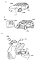
- FIG. 9 illustrates a vehicle using the secondary battery charge state estimation device which is one embodiment of the present invention.
- a secondary battery 8024 of the automobile 8400 illustrated in FIG. 9A can not only drive the electric motor 8406 but also supply power to a light-emitting device such as a headlight 8401 or a room light (not shown).
- the cylindrical secondary battery 600 illustrated in FIG. 7B may be used as the first battery 301 with the conductive plate 613 and the conductive plate 614 interposed therebetween. Good.
- the automobile 8500 shown in FIG. 9B can charge the secondary battery 8024 of the automobile 8500 by receiving power from an external charging facility by a plug-in method, a non-contact power supply method, or the like.
- FIG. 9B illustrates a state where the secondary battery 8024 mounted on the automobile 8500 is charged through the cable 8022 from the ground-installed charging device 8021.
- the charging method, connector standard, and the like may be appropriately performed by a predetermined method such as CHAdeMO (registered trademark) or a combo.
- the charging device 8021 may be a charging station provided in a commercial facility, or may be a household power source.
- the secondary battery 8024 mounted on the automobile 8500 can be charged by power supply from the outside by plug-in technology. Charging can be performed by converting AC power into DC power via a converter such as an ACDC converter.
- the power receiving device can be mounted on the vehicle and charged by supplying power from the ground power transmitting device in a non-contact manner.
- charging can be performed not only when the vehicle is stopped but also during traveling by incorporating a power transmission device on a road or an outer wall.
- this non-contact power feeding method may be used to transmit and receive power between vehicles.
- a solar battery may be provided in the exterior part of the vehicle, and the secondary battery may be charged when the vehicle is stopped or traveling.
- An electromagnetic induction method or a magnetic field resonance method can be used for such non-contact power supply.
- FIG. 9C illustrates an example of a two-wheeled vehicle using the secondary battery charge state estimation device of one embodiment of the present invention.
- a scooter 8600 illustrated in FIG. 9C includes a secondary battery 8602, a side mirror 8601, and a direction indicator lamp 8603.
- the secondary battery 8602 can supply electricity to the direction indicator lamp 8603.
- the scooter 8600 shown in FIG. 9C can store the secondary battery 8602 in the under-seat storage 8604.
- the secondary battery 8602 can be stored in the under-seat storage 8604 even if the under-seat storage 8604 is small.
- FIG. 10 shows an example of a block diagram of the scooter 8600.
- the voltage of the secondary battery 8602 of the scooter 8600 is 48 V or 60 V, and power is supplied to the motor 8606.
- Electric components such as a direction indicator lamp 8603 are supplied with electric power after being stepped down to 12V by a converter.
- An in-wheel motor in which a motor is directly set on a wheel serving as a drive wheel can also be used.
- Charging of the secondary battery 8602 of the scooter 8600 is controlled by the charge control circuit 8608, and the SOC of the secondary battery 8602 is estimated by the neural network unit 8607.
- a regenerative circuit 8621 and a regenerative battery 8622 may be provided.
- the regenerative circuit 8621 and the regenerative battery 8622 can be omitted.
- a signal from the accelerator operation detection unit 8610 is transmitted to the control circuit 8609, and the power of the secondary battery is transmitted to the motor in accordance with the opening of the accelerator.
- a signal from the brake operation detection unit 8611 is transmitted to the control circuit 8609, and the regenerative power at the time of deceleration is once charged in the regenerative battery 8622, and the secondary battery is connected via the charge control circuit 8608.
- Charging to 8602 is performed. These charging histories are learned by the neural network unit 8607, and feedback is performed.
- This embodiment mode can be combined with any of the other embodiment modes as appropriate.
Landscapes
- Engineering & Computer Science (AREA)
- Manufacturing & Machinery (AREA)
- Chemical & Material Sciences (AREA)
- Chemical Kinetics & Catalysis (AREA)
- Electrochemistry (AREA)
- General Chemical & Material Sciences (AREA)
- Power Engineering (AREA)
- Physics & Mathematics (AREA)
- General Physics & Mathematics (AREA)
- Microelectronics & Electronic Packaging (AREA)
- Life Sciences & Earth Sciences (AREA)
- Transportation (AREA)
- Mechanical Engineering (AREA)
- Sustainable Energy (AREA)
- Sustainable Development (AREA)
- Secondary Cells (AREA)
- Measurement Of Resistance Or Impedance (AREA)
- Devices For Checking Fares Or Tickets At Control Points (AREA)
Abstract
La présente invention concerne un système de mesure de capacité de pile rechargeable pour estimer avec une grande précision un état de charge dans un temps court et à un coût faible. Un système d'estimation d'état de charge d'accumulateur selon la présente invention comprend : un moyen d'acquisition de données de séries chronologiques pour des valeurs de tension mesurées et des valeurs de courant mesurées pour un premier accumulateur ; un moyen de normalisation des données de séries chronologiques pour les valeurs de tension mesurées ; un moyen de normalisation des données chronologiques pour les valeurs de courant mesurées ; une unité de création de base de données pour créer une base de données dans laquelle des données résultant de la superposition de données de séries chronologiques ayant un axe de temps vertical et des données de séries chronologiques ayant un axe de temps horizontal sont associées à l'état de charge du premier accumulateur ; et une unité de réseau neuronal pour configurer un réseau neuronal au moyen d'une base de données créée préalablement en tant que données d'apprentissage, recevoir de données pour un deuxième accumulateur résultant de la superposition de données de séries chronologiques ayant un axe de temps vertical et des données de séries chronologiques ayant un axe de temps horizontal, et délivrer en sortie une valeur estimée pour l'état de charge du deuxième accumulateur.
Priority Applications (3)
| Application Number | Priority Date | Filing Date | Title |
|---|---|---|---|
| JP2020515307A JP7337781B2 (ja) | 2018-04-27 | 2019-04-12 | 蓄電装置の充電状態推定システム |
| CN201980027358.4A CN112020656B (zh) | 2018-04-27 | 2019-04-12 | 蓄电装置的充电状态推测的方法以及蓄电装置的充电状态推测系统 |
| US17/050,388 US11493558B2 (en) | 2018-04-27 | 2019-04-12 | Estimation method of state of charge of power storage device and estimation system of state of charge of power storage device |
Applications Claiming Priority (2)
| Application Number | Priority Date | Filing Date | Title |
|---|---|---|---|
| JP2018-086611 | 2018-04-27 | ||
| JP2018086611 | 2018-04-27 |
Publications (1)
| Publication Number | Publication Date |
|---|---|
| WO2019207399A1 true WO2019207399A1 (fr) | 2019-10-31 |
Family
ID=68293770
Family Applications (1)
| Application Number | Title | Priority Date | Filing Date |
|---|---|---|---|
| PCT/IB2019/053018 Ceased WO2019207399A1 (fr) | 2018-04-27 | 2019-04-12 | Procédé d'estimation d'état de charge d'accumulateur et système d'estimation d'état de charge d'accumulateur |
Country Status (5)
| Country | Link |
|---|---|
| US (1) | US11493558B2 (fr) |
| JP (1) | JP7337781B2 (fr) |
| CN (1) | CN112020656B (fr) |
| TW (1) | TWI803623B (fr) |
| WO (1) | WO2019207399A1 (fr) |
Cited By (8)
| Publication number | Priority date | Publication date | Assignee | Title |
|---|---|---|---|---|
| CN112269137A (zh) * | 2020-10-19 | 2021-01-26 | 中山大学 | 一种基于动态参数识别的电池健康状态估算方法 |
| KR20210054467A (ko) * | 2019-11-05 | 2021-05-13 | 도요타 지도샤(주) | 전지 관리 시스템, 전지 관리 방법, 및 세트 전지의 제조 방법 |
| EP3955450A1 (fr) * | 2020-08-12 | 2022-02-16 | SKAIChips Co., Ltd. | Convertisseur cc-cc avec contrôleur intelligent |
| JPWO2022130095A1 (fr) * | 2020-12-16 | 2022-06-23 | ||
| JP2024033844A (ja) * | 2022-08-31 | 2024-03-13 | トヨタ自動車株式会社 | 畳み込みニューラルネットワーク用行列データの生成方法、ならびに、畳み込みニューラルネットワークを用いた学習システムおよび学習装置 |
| CN118659360A (zh) * | 2024-06-21 | 2024-09-17 | 北京智芯微电子科技有限公司 | 光伏功率预测方法、装置、馈线终端、系统、介质及芯片 |
| JP2025518228A (ja) * | 2022-06-02 | 2025-06-12 | エルジー エナジー ソリューション リミテッド | 電池セル寿命診断装置およびその動作方法 |
| JP2025112317A (ja) * | 2021-02-04 | 2025-07-31 | 株式会社野村総合研究所 | 情報処理装置、情報処理方法、プログラム及びデータ構造 |
Families Citing this family (14)
| Publication number | Priority date | Publication date | Assignee | Title |
|---|---|---|---|---|
| US11791640B2 (en) | 2018-12-19 | 2023-10-17 | Semiconductor Energy Laboratory Co., Ltd. | Overdischarge prevention circuit of secondary battery and secondary battery module |
| EP3696744B1 (fr) * | 2019-02-13 | 2026-04-29 | Robert Bosch GmbH | Sauvegarde des ressources des entités physiques dans un environnement partagé |
| US12351044B2 (en) * | 2019-07-30 | 2025-07-08 | Briggs & Stratton, Llc | Battery system and related management system |
| US12660239B2 (en) | 2020-04-24 | 2026-06-16 | Semiconductor Energy Laboratory Co., Ltd. | Imaging device |
| CN112949931B (zh) * | 2021-03-19 | 2024-03-08 | 北京交通大学 | 数据驱动和模型混合的充电站数据的预测方法和装置 |
| JP7408594B2 (ja) * | 2021-03-25 | 2024-01-05 | 本田技研工業株式会社 | 車両及び制御装置 |
| CN114417948B (zh) * | 2021-06-18 | 2025-12-30 | 重庆长安汽车股份有限公司 | 一种基于神经网络预测电池热失控的方法 |
| CN113702836B (zh) * | 2021-07-23 | 2023-08-18 | 国家电网有限公司西北分部 | 一种基于emd-gru锂离子电池荷电状态估计方法 |
| JP7630632B2 (ja) * | 2021-09-28 | 2025-02-17 | 本田技研工業株式会社 | バッテリ特性推定装置、バッテリ特性推定方法、およびプログラム |
| CN114779082B (zh) * | 2022-03-23 | 2023-07-25 | 泉州装备制造研究所 | 一种锂电池单体电压差预测方法及装置 |
| US12700754B2 (en) | 2023-02-07 | 2026-08-04 | Fluid Power Ai, Llc | Systems and methods for monitoring equipment |
| CN115877223B (zh) * | 2023-03-03 | 2023-07-04 | 浙江天能新材料有限公司 | 锂电池检测方法、装置、设备及存储介质 |
| CN116577677B (zh) * | 2023-07-14 | 2023-09-29 | 赣州吉锐新能源科技股份有限公司 | 退役动力电池的放电测试系统及其方法 |
| KR20250114766A (ko) * | 2024-01-22 | 2025-07-29 | 주식회사 배러머신 | 배터리 상태 추정을 위한 심층뉴럴네트워크 학습모델의 학습데이터 레이블링 방법 및 이를 통한 학습 방법 |
Citations (5)
| Publication number | Priority date | Publication date | Assignee | Title |
|---|---|---|---|---|
| JP2004333472A (ja) * | 2003-04-15 | 2004-11-25 | Nippon Soken Inc | 車両用蓄電装置の内部状態検出システム |
| JP2007518973A (ja) * | 2003-12-18 | 2007-07-12 | エルジー・ケム・リミテッド | 神経網を用いたバッテリ残存量推定装置及び方法 |
| JP2007240308A (ja) * | 2006-03-08 | 2007-09-20 | Toyota Motor Corp | バッテリーの制御装置 |
| JP2008232758A (ja) * | 2007-03-19 | 2008-10-02 | Nippon Soken Inc | 二次電池の内部状態検出装置及びニューラルネット式状態量推定装置 |
| WO2018203170A1 (fr) * | 2017-05-03 | 2018-11-08 | Semiconductor Energy Laboratory Co., Ltd. | Réseau neuronal, système de stockage d'énergie, véhicule et dispositif électronique |
Family Cites Families (7)
| Publication number | Priority date | Publication date | Assignee | Title |
|---|---|---|---|---|
| KR100395516B1 (ko) * | 1998-11-19 | 2003-12-18 | 금호석유화학 주식회사 | 비선형등가회로모형을이용한축전장치의특성인자수치화방법및장치 |
| US6794844B2 (en) * | 2001-08-31 | 2004-09-21 | Visteon Global Technologies, Inc. | Method and system for fuel cell control |
| US7554296B2 (en) * | 2005-02-14 | 2009-06-30 | Denso Corporation | Method and apparatus for detecting charged state of secondary battery based on neural network calculation |
| WO2007032382A1 (fr) * | 2005-09-16 | 2007-03-22 | The Furukawa Electric Co., Ltd | Méthode d’estimation de dégradation de cellule secondaire, dispositif d’estimation de dégradation de cellule secondaire et système d’alimentation |
| TW200919210A (en) | 2007-07-18 | 2009-05-01 | Steven Kays | Adaptive electronic design |
| KR102332399B1 (ko) * | 2015-02-06 | 2021-11-29 | 삼성전자주식회사 | 배터리 상태 추정 장치 및 방법 |
| JP7393102B2 (ja) * | 2018-03-16 | 2023-12-06 | 株式会社半導体エネルギー研究所 | 二次電池の異常検出装置 |
-
2019
- 2019-04-12 WO PCT/IB2019/053018 patent/WO2019207399A1/fr not_active Ceased
- 2019-04-12 JP JP2020515307A patent/JP7337781B2/ja active Active
- 2019-04-12 CN CN201980027358.4A patent/CN112020656B/zh not_active Expired - Fee Related
- 2019-04-12 US US17/050,388 patent/US11493558B2/en active Active
- 2019-04-18 TW TW108113517A patent/TWI803623B/zh not_active IP Right Cessation
Patent Citations (5)
| Publication number | Priority date | Publication date | Assignee | Title |
|---|---|---|---|---|
| JP2004333472A (ja) * | 2003-04-15 | 2004-11-25 | Nippon Soken Inc | 車両用蓄電装置の内部状態検出システム |
| JP2007518973A (ja) * | 2003-12-18 | 2007-07-12 | エルジー・ケム・リミテッド | 神経網を用いたバッテリ残存量推定装置及び方法 |
| JP2007240308A (ja) * | 2006-03-08 | 2007-09-20 | Toyota Motor Corp | バッテリーの制御装置 |
| JP2008232758A (ja) * | 2007-03-19 | 2008-10-02 | Nippon Soken Inc | 二次電池の内部状態検出装置及びニューラルネット式状態量推定装置 |
| WO2018203170A1 (fr) * | 2017-05-03 | 2018-11-08 | Semiconductor Energy Laboratory Co., Ltd. | Réseau neuronal, système de stockage d'énergie, véhicule et dispositif électronique |
Cited By (16)
| Publication number | Priority date | Publication date | Assignee | Title |
|---|---|---|---|---|
| JP7151689B2 (ja) | 2019-11-05 | 2022-10-12 | トヨタ自動車株式会社 | 電池管理システム、電池管理方法、及び組電池の製造方法 |
| KR20210054467A (ko) * | 2019-11-05 | 2021-05-13 | 도요타 지도샤(주) | 전지 관리 시스템, 전지 관리 방법, 및 세트 전지의 제조 방법 |
| JP2021077450A (ja) * | 2019-11-05 | 2021-05-20 | トヨタ自動車株式会社 | 電池管理システム、電池管理方法、及び組電池の製造方法 |
| CN112825167A (zh) * | 2019-11-05 | 2021-05-21 | 丰田自动车株式会社 | 电池管理系统、电池管理方法以及电池组的制造方法 |
| KR102587694B1 (ko) | 2019-11-05 | 2023-10-12 | 도요타 지도샤(주) | 전지 관리 시스템, 전지 관리 방법, 및 세트 전지의 제조 방법 |
| EP3955450A1 (fr) * | 2020-08-12 | 2022-02-16 | SKAIChips Co., Ltd. | Convertisseur cc-cc avec contrôleur intelligent |
| US11955888B2 (en) | 2020-08-12 | 2024-04-09 | Skaichips Co., Ltd. | DC-DC converter with intelligent controller |
| CN112269137A (zh) * | 2020-10-19 | 2021-01-26 | 中山大学 | 一种基于动态参数识别的电池健康状态估算方法 |
| WO2022130095A1 (fr) * | 2020-12-16 | 2022-06-23 | 株式会社半導体エネルギー研究所 | Système de batterie de stockage, batterie secondaire et procédé de fonctionnement de système de batterie de stockage |
| JPWO2022130095A1 (fr) * | 2020-12-16 | 2022-06-23 | ||
| JP7721575B2 (ja) | 2020-12-16 | 2025-08-12 | 株式会社半導体エネルギー研究所 | 蓄電池システム、二次電池及び蓄電池システムの動作方法 |
| JP2025112317A (ja) * | 2021-02-04 | 2025-07-31 | 株式会社野村総合研究所 | 情報処理装置、情報処理方法、プログラム及びデータ構造 |
| JP2025518228A (ja) * | 2022-06-02 | 2025-06-12 | エルジー エナジー ソリューション リミテッド | 電池セル寿命診断装置およびその動作方法 |
| JP2024033844A (ja) * | 2022-08-31 | 2024-03-13 | トヨタ自動車株式会社 | 畳み込みニューラルネットワーク用行列データの生成方法、ならびに、畳み込みニューラルネットワークを用いた学習システムおよび学習装置 |
| JP7708045B2 (ja) | 2022-08-31 | 2025-07-15 | トヨタ自動車株式会社 | 畳み込みニューラルネットワークを用いた学習システムおよび学習装置 |
| CN118659360A (zh) * | 2024-06-21 | 2024-09-17 | 北京智芯微电子科技有限公司 | 光伏功率预测方法、装置、馈线终端、系统、介质及芯片 |
Also Published As
| Publication number | Publication date |
|---|---|
| JPWO2019207399A1 (ja) | 2021-07-01 |
| CN112020656B (zh) | 2024-04-19 |
| TWI803623B (zh) | 2023-06-01 |
| US20210116511A1 (en) | 2021-04-22 |
| JP7337781B2 (ja) | 2023-09-04 |
| US11493558B2 (en) | 2022-11-08 |
| TW201945986A (zh) | 2019-12-01 |
| CN112020656A (zh) | 2020-12-01 |
Similar Documents
| Publication | Publication Date | Title |
|---|---|---|
| JP7337781B2 (ja) | 蓄電装置の充電状態推定システム | |
| TWI814765B (zh) | 二次電池的異常檢測裝置、異常檢測方法、充電狀態推測方法、充電狀態推測裝置以及電腦可讀取媒體 | |
| JP7134981B2 (ja) | 二次電池の異常検知システム及び二次電池の異常検出方法 | |
| CN111919128B (zh) | 蓄电装置的充电状态推测方法及蓄电装置的充电状态推测系统 | |
| US11480621B2 (en) | Capacity estimation method and capacity estimation system for power storage device | |
| JP7104065B2 (ja) | 充電制御装置 | |
| CN114402473B (zh) | 全固态锂离子二次电池系统和全固态锂离子二次电池用充电装置 | |
| US9350055B2 (en) | Electric vehicle propulsion system and method utilizing solid-state rechargeable electrochemical cells | |
| US20160344065A1 (en) | Electric vehicle propulsion system and method utilizing solid-state rechargeable electrochemical cells | |
| WO2019175707A1 (fr) | Appareil d'estimation d'état de charge pour batterie secondaire, appareil de détection d'anomalie pour batterie secondaire, procédé de détection d'anomalie pour batterie secondaire et système de gestion pour batterie secondaire | |
| JP7344724B2 (ja) | 全固体リチウムイオン二次電池システム、および全固体リチウムイオン二次電池用充電装置 | |
| JP7787825B2 (ja) | 二次電池の監視システム、及び電気自動車 | |
| CN111133616A (zh) | 固态可充电电化学电池单元 | |
| WO2025088459A1 (fr) | Système de commande de recharge | |
| DE102023136818A1 (de) | Träger für batteriezellen |
Legal Events
| Date | Code | Title | Description |
|---|---|---|---|
| 121 | Ep: the epo has been informed by wipo that ep was designated in this application |
Ref document number: 19793916 Country of ref document: EP Kind code of ref document: A1 |
|
| ENP | Entry into the national phase |
Ref document number: 2020515307 Country of ref document: JP Kind code of ref document: A |
|
| NENP | Non-entry into the national phase |
Ref country code: DE |
|
| 122 | Ep: pct application non-entry in european phase |
Ref document number: 19793916 Country of ref document: EP Kind code of ref document: A1 |