WO2019207672A1 - Mécanisme d'étanchéité, procédé d'étanchéité et machine d'emballage à remplissage vertical - Google Patents
Mécanisme d'étanchéité, procédé d'étanchéité et machine d'emballage à remplissage vertical Download PDFInfo
- Publication number
- WO2019207672A1 WO2019207672A1 PCT/JP2018/016756 JP2018016756W WO2019207672A1 WO 2019207672 A1 WO2019207672 A1 WO 2019207672A1 JP 2018016756 W JP2018016756 W JP 2018016756W WO 2019207672 A1 WO2019207672 A1 WO 2019207672A1
- Authority
- WO
- WIPO (PCT)
- Prior art keywords
- pressing surface
- heater bar
- overlapping portion
- pressing
- seal
- Prior art date
- Legal status (The legal status is an assumption and is not a legal conclusion. Google has not performed a legal analysis and makes no representation as to the accuracy of the status listed.)
- Ceased
Links
Images






Classifications
-
- B—PERFORMING OPERATIONS; TRANSPORTING
- B65—CONVEYING; PACKING; STORING; HANDLING THIN OR FILAMENTARY MATERIAL
- B65B—MACHINES, APPARATUS OR DEVICES FOR, OR METHODS OF, PACKAGING ARTICLES OR MATERIALS; UNPACKING
- B65B51/00—Devices for, or methods of, sealing or securing package folds or closures; Devices for gathering or twisting wrappers, or necks of bags
- B65B51/10—Applying or generating heat or pressure or combinations thereof
Definitions
- the present invention relates to a sealing mechanism, a vertical filling and packaging machine using the sealing mechanism, and a sealing method.
- Japanese Patent No. 2598879 discloses a sealing mechanism having a heater bar and a heater bar receiver. By sandwiching the tubular film between the high-temperature heater bar and the heater bar receiver and pressing the heater bar against the tubular film, the adhesive layers of the tubular film are fused to form a heat seal.
- the heat seal formed in this way usually has a strength that can withstand an impact such as a drop, but may break in a packaging bag filled with a large amount of liquid.
- An object of the present invention is to provide a sealing mechanism and a sealing method capable of forming a heat seal that is strong and hardly breaks.
- the sealing mechanism of the present invention has a heater bar and a heater bar receiver that sandwich the overlapping portion from both sides of the overlapping portion of the film and form a heat seal at the overlapping portion.
- the heater bar is positioned on at least one side of the elongated first pressing surface that heats and melts the overlapping portion while pressing the overlapping portion toward the heater bar receiver, and the short side direction of the first pressing surface, And a second pressing surface having a temperature lower than that of the first pressing surface that presses the overlapping portion toward the heater bar receiver when the pressing surface presses the overlapping portion.
- the overlapping portion of the film is passed between the elongated first pressing surface of the heater bar and the heater bar receiver, and the overlapping portion is pressed against the heater bar receiver by the first pressing surface.
- the first pressing surface is positioned on at least one side in the short direction, Pressing the overlapping portion toward the heater bar receiver with the second pressing surface having a temperature lower than that of the first pressing surface.
- the second pressing surface is provided on at least one side in the short direction of the first pressing surface for heat sealing. Since the second pressing surface is lower in temperature than the first pressing surface, the portion pressed by the second pressing surface of the overlapping portion has a degree of melting higher than the portion heated and melted by the first pressing surface. Small or not melt at all. There is a possibility that a part of the overlapping portion heated and melted by the first pressing surface is thinned by being pushed out of the first pressing surface by the pressing force of the first pressing surface. The meat phenomenon is one factor that reduces the strength of the heat seal. According to the present invention, it is difficult for the heated and melted portion of the overlapping portion to escape to the outside of the first pressing surface, so that the thickness reduction is suppressed. Therefore, it is possible to form a heat seal that is high in strength and hardly breaks.
- FIG. 4 is an enlarged view of a heater bar and a heater bar receiver of the lateral seal mechanism shown in FIG. 3. It is the A section enlarged view of FIG. 4A. It is the binarized photograph of the cross section of the horizontal seal
- FIG. 5A It is the A section enlarged view of FIG. 5A. It is the binarized photograph of the cross section of the horizontal seal of a comparative example. It is a side view of the heater bar and heater bar receiver of the vertical filling packaging machine which concerns on the 2nd Embodiment of this invention. It is a principal part perspective view of the vertical filling packaging machine which concerns on the 3rd Embodiment of this invention.
- the X direction is the horizontal direction in which the horizontal sealing device moves
- the Y direction is the horizontal direction perpendicular to the X direction, that is, the direction parallel to the width direction of the horizontal sealing device or the tubular film
- the Z direction Means a vertical direction orthogonal to the X direction and the Y direction.
- FIG. 1 is a perspective view of a main part of a vertical filling and packaging machine 1.
- the vertical filling and packaging machine 1 includes a bag making guide 2, a vertical sealing mechanism 3, a conveying roller pair 4, a feeding pipe 5, a squeeze roller 6, and a horizontal sealing mechanism 7.
- the bag-making guide 2 has a three-dimensional surface shape, and the sheet-like film F1 is folded into a cylindrical shape so that both side edges in the width direction overlap each other, and the transport direction of the folded film is directed downward in the vertical direction. Change.
- the vertical seal mechanism 3 is disposed below the bag making guide 2 and heat seals both side edges of the sheet-like film F1 that are overlapped with each other.
- the vertical seal mechanism 3 includes a heater bar 3a in which a heater (not shown) is incorporated, and a heater bar receiver 3b.
- the vertical seal mechanism 3 heats both side edges extending in the vertical direction of the film F1 with the heater bar 3a, melts the film F1, and forms a vertical seal, that is, a heat seal extending in the vertical direction.
- the film on which the vertical seal is formed is referred to as a cylindrical film F2.
- the horizontal cross section of the tubular film F2 is not limited to a circular shape, and may be an oval shape or the like as long as the shape is continuous in the circumferential direction.
- the vertical sealing mechanism 3 is provided only on one edge in the Y direction (width direction) of the tubular film F2, but may be provided on both edges.
- the conveying roller pair 4 (conveying means) is disposed below the vertical seal mechanism 3.
- the conveyance roller pair 4 is provided on both sides in the Y direction of the tubular film F2 to avoid interference with the contents, and grips both side edges in the Y direction of the tubular film F2 to hold the tubular film F2 in the vertical direction. Transport downward.
- the charging pipe 5 extends vertically from above the bag making guide 2 to the inside of the tubular film F2, and fills the inside of the tubular film F2 with contents such as liquid.
- the lower end of the input pipe 5 is located below the conveying roller pair 4 and above the squeeze roller 6.
- the squeeze roller 6 is disposed below the lower end of the input pipe 5 and the conveying roller pair 4 and above the lateral seal mechanism 7.
- the squeeze roller 6 presses the tubular film F2 from both sides in the Y direction (width direction) when the tubular film F2 is being transported by the transport roller pair 4, and the contents filled in the tubular film F2 are vertically moved.
- Divide into The squeeze roller 6 forms an empty filling portion where a horizontal seal is formed on the tubular film F2. In other words, the squeeze roller 6 eliminates the contents at the place where the horizontal seal is to be formed, thereby improving the reliability of the horizontal seal.
- the horizontal seal mechanism 7 is disposed below the squeeze roller 6 and forms a horizontal seal.
- the horizontal sealing mechanism 7 uses heat conduction from a heater, unlike an impulse method in which a heat ray directly heats a film. That is, the cylindrical film F2 is heated by the heater bar 8 that has been heated to a high temperature by the heater. Since the heat stored in the heater bar 8 is used, a sufficient amount of heat can be given to the tubular film F2 even when impurities such as water remain in the place where the horizontal seal is to be formed. Further, the lateral seal mechanism 7 that utilizes heat conduction from the heater is superior in production efficiency compared to the impulse method.
- the horizontal seal mechanism 7 is provided with a cooling mechanism, and immediately cools the high-temperature horizontal seal to express the sealing performance of the horizontal seal at an early stage. Further, the horizontal seal mechanism 7 includes a cutter (not shown), and the horizontal seal is cut at an intermediate position in the vertical direction of the horizontal seal to separate the tubular film F2 filled with the contents into individual packages. To do. Details of the lateral seal mechanism 7 will be described later.
- step (d) of FIG. 2 in the process of making the previous package of the target package (hereinafter referred to as the preceding package), the tubular film F ⁇ b> 2 is subjected to the first lateral by the lateral seal mechanism 7.
- a seal LS1 (described as LS1 / LS2 in step (d) in FIG. 2) is formed.
- the first horizontal seal LS1 is a portion that becomes the upper horizontal seal of the preceding package and the lower horizontal seal of the target package.
- step (e) of FIG. 2 the horizontal sealing mechanism 7 and the squeeze roller 6 are separated from the cylindrical film F2, and the charging pipe 5 (FIG. 2) is disposed above the first horizontal seal LS1 of the cylindrical film F2. Is filled with the contents C.
- the preceding package is separated by a cutter built in the horizontal seal mechanism 7.
- steps (d) and (e) in FIG. 2 the conveying roller pair 4 (not shown in FIG. 2) is stopped and the tubular film F2 is stationary.
- step (a) of FIG. 2 the cylindrical film F ⁇ b> 2 is conveyed downward by the conveying roller pair 4, and the conveyance of the cylindrical film F ⁇ b> 2 is temporarily stopped, and the contents C are further removed from the charging pipe 5. Fill. Although not shown, a vertical seal is formed on the upstream side at this time.
- steps (b) and (c) of FIG. 2 the cylindrical film F ⁇ b> 2 is pressed by the squeeze roller 6 while the cylindrical roller F ⁇ b> 2 is conveyed downward by the conveying roller pair 4. Thereby, a part of the contents C filled in the tubular film F2 is separated into an amount for one package.
- step (d) of FIG. 2 the second horizontal seal LS ⁇ b> 2 is formed in the upper region of the contents C of the target package by the horizontal seal mechanism 7.
- the squeeze roller 6 is separated from the tubular film F2, and the center of the second horizontal seal LS2 in the vertical direction is cut with a cutter built in the horizontal seal mechanism 7 to A target package filled with the object C is formed.
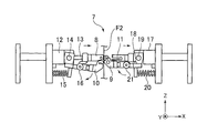
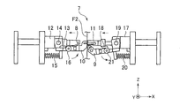
- FIG. 3A and 3B are side views of the lateral seal mechanism 7.
- FIG. 3A shows a state where the heater bar 8 and the heater bar receiver 9 face each other
- FIG. 3B shows a state where the cooling bar 10 and the cooling bar receiver 11 face each other.
- the horizontal sealing mechanism 7 includes a heater bar 8 and a heater bar receiver 9 that faces the heater bar 8.
- the heater bar 8 and the heater bar receiver 9 sandwich the tubular film F2 from both sides in the X direction of the tubular film F2, and form a horizontal seal on the tubular film F2, that is, a heat seal extending in the Y direction.
- the horizontal seal mechanism 7 further includes a cooling bar 10 and a cooling bar receiver 11 facing the cooling bar 10.
- the cooling bar 10 and the cooling bar receiver 11 constitute a cooling means for a lateral seal.
- the cooling bar 10 and the cooling bar receiver 11 sandwich the horizontal seal immediately after being formed by the heater bar 8 and the heater bar receiver 9, and cool the horizontal seal.
- the heater bar 8 is driven by the cylinder 12 so as to be movable back and forth in the X direction with respect to the tubular film F2.
- a cam 13 is provided below the heater bar 8.
- the cooling bar 10 is supported so as to be rotatable around the rotation shaft 14 and is urged counterclockwise by a spring 15.
- a roller 16 is provided at a position facing the cam 13 of the cooling bar 10.
- the cooling bar receiver 11 is driven by the cylinder 17 so as to be movable back and forth in the X direction with respect to the tubular film F2.
- a cam 18 is provided below the cooling bar receiver 11.
- the heater bar receiver 9 is supported so as to be rotatable around a rotation shaft 19 and is urged clockwise by a spring 20.
- a roller 21 is provided at a position facing the cam 18 of the heater bar receiver 9.
- the heater bar 8 is driven to a forward position where the cylindrical film F2 is pressed.
- the roller 16 of the cooling bar 10 rides on the cam 13 of the heater bar 8, and the cooling bar 10 rotates clockwise against the urging force of the spring 15 and moves to the retracted position.
- the cooling bar receiver 11 is driven to the retracted position away from the tubular film F2.
- the roller 21 of the heater bar receiver 9 is disengaged from the cam 18, and the heater bar receiver 9 is rotated clockwise by the urging force of the spring 20 and moves to a position facing the heater bar 8.
- the tubular film F2 is sandwiched between the heater bar 8 and the heater bar receiver 9, and a horizontal seal is formed on the tubular film F2 by the heat of the heater bar 8.
- the cooling bar receiver 11 is driven to a forward position where the tubular film F2 is pressed.
- the roller 21 of the heater bar receiver 9 rides on the cam 18 of the cooling bar receiver 11 against the urging force of the spring 20, and the heater bar receiver 9 rotates counterclockwise and moves to the retracted position.
- the heater bar 8 is driven to a retracted position away from the tubular film F2.
- the roller 16 of the cooling bar 10 is disengaged from the cam 13 of the heater bar 8, and the cooling bar 10 is rotated counterclockwise by the urging force of the spring 15 and moves to a position facing the cooling bar receiver 11.
- the tubular film F2 is sandwiched between the cooling bar 10 and the cooling bar receiver 11, and the heated horizontal seal is cooled by the heater bar 8.
- One packaging bag is separated from the tubular film F2 by advancing a cutter (not shown) built in the cooling bar receiver 11 toward the tubular film F2. Since the horizontal seal is sandwiched between the cooling bar 10 and the cooling bar receiver 11, the cutting position is stable, and the deviation of the cutting position can be suppressed. When the nipping by the cooling bar 10 and the cooling bar receiver 11 is released, the separated packaging bag falls downward.
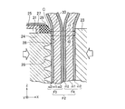
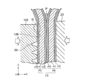
- FIG. 4A is an enlarged view of the heater bar 8 and the heater bar receiver 9, and FIG. 4B is an enlarged view of a portion A in FIG. 4A.
- FIG. 4C is a photograph of a cross section of the created horizontal seal, which is binarized.
- FIG. 4A shows a state when the heater bar 8 and the heater bar receiver 9 are in contact with the tubular film F2, and the pressing member 26 of the heater bar 8 is separated from the tubular film F2.
- the tubular film F2 is actually pressed by the heater bar 8 and the heater bar receiver 9, the pressing member 26 of the heater bar 8 comes into contact with the tubular film F2.
- the cylindrical film F2 entering between the heater bar 8 and the heater bar receiver 9 is composed of two sheet-like films F3 and F4, and a horizontal seal is formed by heat-sealing them.
- the configuration of the films F3 and F4 is not particularly limited, but is an example of a multilayer film in which an adhesive layer m2 is laminated on both sides of a base material m1 such as nylon.
- the adhesive layer m2 is made of, for example, polyethylene (PE) or polypropylene (PP), and is fused to each other by melting at a high temperature and then solidifying. PE has high adhesive strength but has a peculiar odor, and is not preferred when water or the like is filled as the contents.
- PP has a low adhesive strength but has little odor and is preferably used when water or the like is filled. Therefore, breakage of the lateral seal is more likely to occur with PP than with PE.
- water is filled as the contents, and PP is used as the adhesive layer m2.
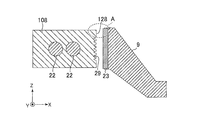
- FIGS. 4A to 4C are views similar to FIGS. 4A to 4C showing the heater bar 108 of the comparative example.
- the heater bar 108 has a built-in heater 22 and a pressing surface 128 that faces the receiving mat 23 of the heater bar receiver 9.
- a plurality of grooves 29 extending in the Y direction are formed on the pressing surface 128.
- the pressing surface 128 is flat except for the region where the groove 29 is formed.
- FIG. 5B since the two films F3 and F4 are pressed while being heated, a part of the melted adhesive layer m2 in the vicinity of the end of the heater bar 108 in the Z direction is indicated by an arrow. And the heater bar receiver 9 are pushed out of the space.
- the extruded adhesive layer m2 accumulates in the vicinity of the Y-shaped intersection of the two films F3 and F4 (indicated by reference numeral P in FIGS. 5B and 5C) and solidifies as it is. A portion of the adhesive layer m2 in the vicinity of the end portion in the Z direction of the heater bar 108 flows out of the heater bar 108, so that the thickness decreases after solidification. In particular, since the adhesive layer m2 in contact with the heater bar 108 is heated to the highest temperature and fluidization proceeds, this phenomenon appears remarkably, and an uneven thinning portion Q appears on the surface facing the heater bar 108.
- the film thickness of the adhesive layer m2 increases immediately outside the heater bar 108, the film thickness decreases near the edge of the heater bar 108 inside the heater bar 108, and the film thickness becomes substantially constant at the center in the Z direction.
- the film F3, F4 has non-uniform film thickness, and breakage tends to occur.
- the heater bar 8 of the present embodiment has a main body 24, a pair of heat insulating materials 25, and a pair of pressing members 26.
- the pair of heat insulating materials 25 and the pair of pressing members 26 are held by the main body 24 by a pressing plate 27.
- the main body 24 is made of a metal such as brass, has a built-in heater 22, and has a first pressing surface 28 facing the heater bar receiver 9. Similar to the heater bar 108, a plurality of grooves 29 extending in the Y direction are formed on the first pressing surface 28.
- the first pressing surface 28 heats and melts the tubular film F ⁇ b> 2 while pressing the tubular film F ⁇ b> 2 toward the receiving mat 23 of the heater bar receiver 9.
- the receiving mat 23 is made of silicon rubber.
- the pair of pressing members 26 are located on both sides in the short direction (Z direction) of the first pressing surface 28, and when the first pressing surface 28 presses the cylindrical film F 2, the cylindrical film F 2 is attached to the heater bar receiver 9. Press toward the receiving mat 23.
- the surface on which the pressing member 26 presses the tubular film F ⁇ b> 2 (hereinafter referred to as the second pressing surface 30) has a rectangular shape whose longitudinal direction is the Y direction, and the dimension in the Y direction is substantially the same as that of the first pressing surface 28. The same.
- the Z-direction dimension of the second pressing surface 30 is much smaller than the Z-direction dimension of the first pressing surface 28, and is about 2 mm in one example.
- the pressing member 26 is not limited as long as it has elasticity and has heat resistance to a temperature of about 190 ° C., but is preferably made of silicon rubber.
- the heat insulating material 25 is formed of a material having a lower thermal conductivity than the main body 24 such as a glass cloth base epoxy resin laminate, and is located on the back surface of the pressing member 26 when viewed from the heater bar receiver 9. For this reason, the heat transmitted from the heater 22 to the holding member 26 is reduced as compared with the case where the heat insulating material 25 is not provided. Furthermore, the heat insulating material 25 has a concave portion 31 that opens to face the main body 24, and heat transmitted from the heater 22 to the pressing member 26 is further suppressed by the heat insulating performance of the air in the concave portion 31.
- the recess 31 is a groove extending over the entire length of the heat insulating material 25 in the X direction.
- the second pressing surface 30 is cooler than the first pressing surface 28. Therefore, the amount of heat input to the adhesive layer m2 in contact with the second pressing surface 30 is smaller than that in the comparative example, and the adhesive layer m2 remains at a position facing the pressing member 26 with almost no flow.
- the adhesive layer m ⁇ b> 2 in contact with the second pressing surface 30 functions as a barrier that blocks the flow of the molten adhesive layer m ⁇ b> 2 that is about to be pushed out of the heater bar 8 in the vicinity of the end of the heater bar 8 in the Z direction. As a result, as shown in FIG. 4C, the film thickness of the adhesive layer m2 is less likely to be uneven, and the possibility of breakage is reduced.
- the temperature of the holding member 26 is approximately the same as that of the main body 24 even if the heat insulating material 25 is provided after the heater 22 is energized. May reach up to. However, since the heat of the pressing member 26 escapes to the tubular film F2 by forming the horizontal seal several times, and the heat from the heater 22 is blocked by the heat insulating material 25, the temperature of the second pressing surface 30 decreases. To do.
- the distance d1 between the second pressing surface 30 and the receiving mat 23 of the heater bar receiver 9 is the first pressing surface 28 and the heater bar.
- the distance between the receiving 9 and the receiving mat 23 is larger than the distance d2.
- the distance d1 is preferably about 0.1 to 0.3 mm larger than the distance d2, and it is preferable that at least the second pressing surface 30 does not protrude from the first pressing surface 28 toward the tubular film F2.
- some liquid may remain at a position where a horizontal seal is to be formed even if the squeeze roller 6 is used.
- the interval d1 By setting the interval d1 to be slightly larger than the interval d2, it becomes easy for the liquid to be discharged out of the heater bar 8, and it is possible to prevent the liquid from remaining in the horizontal seal, which causes a decrease in the seal strength.
- both end regions in the short direction (Z direction) of the first pressing surface 28 are flat, the distance in the X direction between the heater bar 8 and the heater bar receiver 9 is substantially constant. Further, since the pressing member 26 is in close contact with the main body 24 in the short direction (Z direction) of the heater bar 8, the molten adhesive layer m ⁇ b> 2 does not enter between the pressing member 26 and the main body 24. Accordingly, the fluidity of the adhesive layer m2 melted between the heater bar 8 and the heater bar receiver 9 is ensured, and the film thickness of the lateral seal becomes substantially constant.
- the pressing member 26 Since the pressing member 26 is made of silicon rubber, it is elastically deformed when the cylindrical film F2 is pressed. Thus, the pressing member 26 can hold the tubular film F2 while applying a pressing force that does not become excessive to the tubular film F2. Therefore, the presser member 26 is prevented from biting into the tubular film F2, and leakage from the adhesive layer m2 due to the presser member 26 biting is less likely to occur. Further, the pressing member 26 is chamfered (indicated by reference numeral C in FIG. 4B) at the corner opposite to the main body 24. As described above, the second pressing surface 30 is colder than the first pressing surface 28, but the chamfering C reduces the contact area between the pressing member 26 and the cylindrical film F2, so that the pressing member 26 has a cylindrical shape. The possibility that the film F2 is fused can be further reduced.
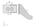
- FIG. 6 is a view similar to FIG. 4A of the heater bar 208 of the vertical filling and packaging machine 1 according to the second embodiment of the present invention.
- the heat insulation part 86 is used as a pressing member. That is, the pressing member 26 made of silicon rubber according to the first embodiment is omitted, and the heat insulating portion 83 faces the receiving mat 23 of the heater bar receiver 9. Since the presser member 26 is omitted, the presser plate 27 is also omitted. In this embodiment, since the pressing member 26 made of silicon rubber is not necessary, the number of parts is reduced and the configuration is simplified. Further, it is not necessary to periodically replace the presser member 26, and maintenance work is reduced.
- FIG. 7 is a view similar to FIG. 1 of the vertical filling and packaging machine 1 according to the third embodiment of the present invention.
- the cooling bar 10 / cooling bar receiver 11 is separated from the heater bar 8 / heater bar receiver 9. That is, the cooling bar 10 is installed below the heater bar 8, and the cooling bar receiver 11 is installed below the heater bar receiver 9. Since the heater bar 8 / heater bar receiver 9 and the cooling bar 10 / cooling bar receiver 11 only need to be able to perform simple forward and backward movements in the X direction, these structures are simplified.
- the structures of the main body 24, the heat insulating material 25, and the pressing member 26 are the same as those in the first embodiment and the second embodiment, and the effects thereof are the same as those in these embodiments.
- the advantages of the vertical filling and packaging machine 1 according to each embodiment described above are as follows. (1) As described above, the film thickness of the horizontal seal is made uniform, and the possibility of breakage is reduced. As a result, a thinner film can be used, thereby reducing packaging costs. (2) Since a thin film can be used, the film length per roll can be increased, and the frequency of roll replacement is reduced. For this reason, the number of packages that can be produced per unit time increases. In addition, since a thin film can be used, the amount of heat (heating time) input to the heater bar is reduced. For this reason, the number of packages that can be produced per unit time is further increased, and the electricity bill can be saved. (3) Since a thin film requires less heat input for forming a horizontal seal, the adhesive layer is more unlikely to melt.
- Example 2 A package body filled with 15 ° C. water was prepared using the heater bar 108 (comparative example) shown in FIG. 5A, and the package body was dropped by 50 cm after a predetermined time (less than 1 hour), and the presence or absence of damage was examined.
- the packaging speed (the number of packages produced per minute) was 14.
- the temperature of the heater bar was 155 ° C.
- the temperature of the heat bar receiver (silicon mat) was 185 ° C.
- a drop test was performed on 20 packages, and 7 packages were damaged.
- a package filled with water at 14 ° C. was prepared, and after a certain time (less than 1 hour), the package was dropped by 50 cm and examined for damage.
- the temperature of the heater bar was 165 ° C.
- the temperature of the heater bar receiver (silicon mat) was 175 ° C.
- a drop test was performed on 20 packages, and none of the packages was damaged.
- the sealing mechanism of the present invention can be applied to a vertical seal.
- the pressing member 26 is provided on both sides of the first pressing surface 28 in the short direction (Z direction), but may be provided only on one side.
- the heat insulating material 25 on the back surface of the pressing member 26 may be omitted, and only the pressing member 26 that is long in the X direction may be provided on the main body 24.
- this invention is not limited to formation of the heat seal to a cylindrical film, but is widely applied to formation of the heat seal to the overlap part of a film.
- the overlapping portion of the film is the cylindrical film F2 itself, but the present invention can be similarly applied to the formation of a heat seal to the overlapping portions of a plurality of independent films.
Landscapes
- Engineering & Computer Science (AREA)
- Mechanical Engineering (AREA)
- Package Closures (AREA)
- Containers And Plastic Fillers For Packaging (AREA)
Abstract
La présente invention a pour objet de former un joint thermosoudé qui présente une résistance élevée et ne se rompt pas facilement. Le mécanisme d'étanchéité selon l'invention comprend : une barre chauffante (8) et un récepteur de barre chauffante (9) qui prennent en sandwich une partie en chevauchement d'un film (F2) à partir des deux surfaces de la partie en chevauchement et forment un joint thermosoudé au niveau de la partie en chevauchement. La barre chauffante (8) comprend : une première surface de pressage mince (28) qui chauffe et fait fondre la partie en chevauchement tout en pressant la partie en chevauchement vers le récepteur de barre chauffante (9) ; et une deuxième surface de pressage (30) qui est positionnée sur au moins un côté dans le sens de la largeur de la première surface de pressage (28), presse la partie en chevauchement vers le récepteur de barre de chauffage (9) lorsque la première surface de pressage (28) a pressé la partie en chevauchement, et présente une température inférieure à celle de la première surface de pressage (28).
Priority Applications (1)
| Application Number | Priority Date | Filing Date | Title |
|---|---|---|---|
| PCT/JP2018/016756 WO2019207672A1 (fr) | 2018-04-25 | 2018-04-25 | Mécanisme d'étanchéité, procédé d'étanchéité et machine d'emballage à remplissage vertical |
Applications Claiming Priority (1)
| Application Number | Priority Date | Filing Date | Title |
|---|---|---|---|
| PCT/JP2018/016756 WO2019207672A1 (fr) | 2018-04-25 | 2018-04-25 | Mécanisme d'étanchéité, procédé d'étanchéité et machine d'emballage à remplissage vertical |
Publications (1)
| Publication Number | Publication Date |
|---|---|
| WO2019207672A1 true WO2019207672A1 (fr) | 2019-10-31 |
Family
ID=68294870
Family Applications (1)
| Application Number | Title | Priority Date | Filing Date |
|---|---|---|---|
| PCT/JP2018/016756 Ceased WO2019207672A1 (fr) | 2018-04-25 | 2018-04-25 | Mécanisme d'étanchéité, procédé d'étanchéité et machine d'emballage à remplissage vertical |
Country Status (1)
| Country | Link |
|---|---|
| WO (1) | WO2019207672A1 (fr) |
Cited By (1)
| Publication number | Priority date | Publication date | Assignee | Title |
|---|---|---|---|---|
| US12012249B2 (en) | 2017-06-08 | 2024-06-18 | Orihiro Engineering Co., Ltd. | Vertical bag-making/filling/packaging machine, manufacturing method of film packaging bag with content |
Citations (3)
| Publication number | Priority date | Publication date | Assignee | Title |
|---|---|---|---|---|
| JP2003118745A (ja) * | 2001-10-11 | 2003-04-23 | Asahi Kasei Pax Corp | 雑菌遮断性口栓付き密封袋及びその製造方法 |
| JP2006347601A (ja) * | 2005-06-17 | 2006-12-28 | Tokyo Autom Mach Works Ltd | 縦形製袋充填機 |
| JP2014129133A (ja) * | 2012-12-29 | 2014-07-10 | Uni Charm Corp | 帯状シートにシールを施す融着装置 |
-
2018
- 2018-04-25 WO PCT/JP2018/016756 patent/WO2019207672A1/fr not_active Ceased
Patent Citations (3)
| Publication number | Priority date | Publication date | Assignee | Title |
|---|---|---|---|---|
| JP2003118745A (ja) * | 2001-10-11 | 2003-04-23 | Asahi Kasei Pax Corp | 雑菌遮断性口栓付き密封袋及びその製造方法 |
| JP2006347601A (ja) * | 2005-06-17 | 2006-12-28 | Tokyo Autom Mach Works Ltd | 縦形製袋充填機 |
| JP2014129133A (ja) * | 2012-12-29 | 2014-07-10 | Uni Charm Corp | 帯状シートにシールを施す融着装置 |
Cited By (1)
| Publication number | Priority date | Publication date | Assignee | Title |
|---|---|---|---|---|
| US12012249B2 (en) | 2017-06-08 | 2024-06-18 | Orihiro Engineering Co., Ltd. | Vertical bag-making/filling/packaging machine, manufacturing method of film packaging bag with content |
Similar Documents
| Publication | Publication Date | Title |
|---|---|---|
| US5678392A (en) | Residual product removing apparatus | |
| US8376923B2 (en) | Bag-making packaging machine | |
| CN104853900B (zh) | 纵向封缄装置 | |
| JP7407816B2 (ja) | 製袋機、製袋方法 | |
| JP6651540B2 (ja) | 折り畳み可能型の柔軟なパッケージを密封する為の方法 | |
| JP7262146B1 (ja) | 縦型製袋充填包装機、内容物入りフィルム包装袋の製造方法、内容物入りフィルム包装袋 | |
| KR101253662B1 (ko) | 초음파 융착기가 구성된 스틱형 제품 포장기 | |
| WO2019207672A1 (fr) | Mécanisme d'étanchéité, procédé d'étanchéité et machine d'emballage à remplissage vertical | |
| JP6349653B2 (ja) | ジッパー付パウチおよびその製造方法 | |
| KR20150028038A (ko) | 2단 분리형 가로 실링 접합장치를 구비한 2열 공급식 스틱형 제품 포장기 | |
| JP4418085B2 (ja) | 包装体のシール装置 | |
| JP2012254602A (ja) | 熱接着方法および熱接着装置 | |
| JP2002523258A (ja) | 熱封止パックを製造する方法およびその方法を実施する用具 | |
| EP3228549B1 (fr) | Appareil d'emballage d'oreillers à agencement horizontal et procédé d'emballage d'oreillers à agencement horizontal | |
| JP2020050374A (ja) | ヒートシールロール用シール刃 | |
| JPH0315297Y2 (fr) | ||
| JP4610045B2 (ja) | ハーフカット形成装置 | |
| JP7653232B2 (ja) | 包装用フィルムの超音波シール方法および包装機 | |
| JP3025266B1 (ja) | 縦型充填包装機の横シ―ル装置 | |
| AU2020419611B2 (en) | Sealing element for sealing a package and device for sealing a package | |
| JP6980057B2 (ja) | 内容物入りフィルム包装袋、縦型製袋充填包装機、内容物入りフィルム包装袋の製造方法 | |
| US20050167040A1 (en) | Layered web sealing and severing head | |
| JP2019031014A (ja) | 易カット構造を有する包装袋の製造方法 | |
| JPH10203502A (ja) | 縦型製袋充填包装方法におけるエンドシールの強化方法 | |
| KR101629685B1 (ko) | 다층 복합 비닐 및 합성수지 포대 |
Legal Events
| Date | Code | Title | Description |
|---|---|---|---|
| 121 | Ep: the epo has been informed by wipo that ep was designated in this application |
Ref document number: 18916809 Country of ref document: EP Kind code of ref document: A1 |
|
| NENP | Non-entry into the national phase |
Ref country code: DE |
|
| 122 | Ep: pct application non-entry in european phase |
Ref document number: 18916809 Country of ref document: EP Kind code of ref document: A1 |
|
| NENP | Non-entry into the national phase |
Ref country code: JP |