WO2019207756A1 - 空間光通信装置 - Google Patents
空間光通信装置 Download PDFInfo
- Publication number
- WO2019207756A1 WO2019207756A1 PCT/JP2018/017163 JP2018017163W WO2019207756A1 WO 2019207756 A1 WO2019207756 A1 WO 2019207756A1 JP 2018017163 W JP2018017163 W JP 2018017163W WO 2019207756 A1 WO2019207756 A1 WO 2019207756A1
- Authority
- WO
- WIPO (PCT)
- Prior art keywords
- signal
- light
- optical
- unit
- phase
- Prior art date
- Legal status (The legal status is an assumption and is not a legal conclusion. Google has not performed a legal analysis and makes no representation as to the accuracy of the status listed.)
- Ceased
Links
Images


Classifications
-
- H—ELECTRICITY
- H04—ELECTRIC COMMUNICATION TECHNIQUE
- H04B—TRANSMISSION
- H04B10/00—Transmission systems employing electromagnetic waves other than radio-waves, e.g. infrared, visible or ultraviolet light, or employing corpuscular radiation, e.g. quantum communication
- H04B10/11—Arrangements specific to free-space transmission, i.e. transmission through air or vacuum
- H04B10/112—Line-of-sight transmission over an extended range
- H04B10/1123—Bidirectional transmission
- H04B10/1127—Bidirectional transmission using two distinct parallel optical paths
-
- H—ELECTRICITY
- H04—ELECTRIC COMMUNICATION TECHNIQUE
- H04B—TRANSMISSION
- H04B10/00—Transmission systems employing electromagnetic waves other than radio-waves, e.g. infrared, visible or ultraviolet light, or employing corpuscular radiation, e.g. quantum communication
- H04B10/11—Arrangements specific to free-space transmission, i.e. transmission through air or vacuum
- H04B10/118—Arrangements specific to free-space transmission, i.e. transmission through air or vacuum specially adapted for satellite communication
-
- H—ELECTRICITY
- H04—ELECTRIC COMMUNICATION TECHNIQUE
- H04B—TRANSMISSION
- H04B10/00—Transmission systems employing electromagnetic waves other than radio-waves, e.g. infrared, visible or ultraviolet light, or employing corpuscular radiation, e.g. quantum communication
- H04B10/11—Arrangements specific to free-space transmission, i.e. transmission through air or vacuum
- H04B10/112—Line-of-sight transmission over an extended range
- H04B10/1123—Bidirectional transmission
- H04B10/1125—Bidirectional transmission using a single common optical path
-
- H—ELECTRICITY
- H04—ELECTRIC COMMUNICATION TECHNIQUE
- H04B—TRANSMISSION
- H04B10/00—Transmission systems employing electromagnetic waves other than radio-waves, e.g. infrared, visible or ultraviolet light, or employing corpuscular radiation, e.g. quantum communication
- H04B10/29—Repeaters
- H04B10/291—Repeaters in which processing or amplification is carried out without conversion of the main signal from optical form
- H04B10/297—Bidirectional amplification
- H04B10/2972—Each direction being amplified separately
-
- H—ELECTRICITY
- H04—ELECTRIC COMMUNICATION TECHNIQUE
- H04B—TRANSMISSION
- H04B10/00—Transmission systems employing electromagnetic waves other than radio-waves, e.g. infrared, visible or ultraviolet light, or employing corpuscular radiation, e.g. quantum communication
- H04B10/50—Transmitters
- H04B10/516—Details of coding or modulation
- H04B10/548—Phase or frequency modulation
-
- H—ELECTRICITY
- H04—ELECTRIC COMMUNICATION TECHNIQUE
- H04B—TRANSMISSION
- H04B10/00—Transmission systems employing electromagnetic waves other than radio-waves, e.g. infrared, visible or ultraviolet light, or employing corpuscular radiation, e.g. quantum communication
- H04B10/60—Receivers
- H04B10/61—Coherent receivers
- H04B10/614—Coherent receivers comprising one or more polarization beam splitters, e.g. polarization multiplexed [PolMux] X-PSK coherent receivers, polarization diversity heterodyne coherent receivers
-
- G—PHYSICS
- G02—OPTICS
- G02B—OPTICAL ELEMENTS, SYSTEMS OR APPARATUS
- G02B27/00—Optical systems or apparatus not provided for by any of the groups G02B1/00 - G02B26/00, G02B30/00
- G02B27/0087—Phased arrays
-
- G—PHYSICS
- G02—OPTICS
- G02F—OPTICAL DEVICES OR ARRANGEMENTS FOR THE CONTROL OF LIGHT BY MODIFICATION OF THE OPTICAL PROPERTIES OF THE MEDIA OF THE ELEMENTS INVOLVED THEREIN; NON-LINEAR OPTICS; FREQUENCY-CHANGING OF LIGHT; OPTICAL LOGIC ELEMENTS; OPTICAL ANALOGUE/DIGITAL CONVERTERS
- G02F1/00—Devices or arrangements for the control of the intensity, colour, phase, polarisation or direction of light arriving from an independent light source, e.g. switching, gating or modulating; Non-linear optics
- G02F1/29—Devices or arrangements for the control of the intensity, colour, phase, polarisation or direction of light arriving from an independent light source, e.g. switching, gating or modulating; Non-linear optics for the control of the position or the direction of light beams, i.e. deflection
- G02F1/292—Devices or arrangements for the control of the intensity, colour, phase, polarisation or direction of light arriving from an independent light source, e.g. switching, gating or modulating; Non-linear optics for the control of the position or the direction of light beams, i.e. deflection by controlled diffraction or phased-array beam steering
-
- H—ELECTRICITY
- H04—ELECTRIC COMMUNICATION TECHNIQUE
- H04B—TRANSMISSION
- H04B10/00—Transmission systems employing electromagnetic waves other than radio-waves, e.g. infrared, visible or ultraviolet light, or employing corpuscular radiation, e.g. quantum communication
- H04B10/11—Arrangements specific to free-space transmission, i.e. transmission through air or vacuum
- H04B10/112—Line-of-sight transmission over an extended range
Definitions
- the present invention relates to a spatial optical communication apparatus that performs communication by outputting laser light to a space.
- Spatial optical communication device is a small and excellent portability for microwave communication device that communicates using a general microwave, has a small beam spread and concealment, is not restricted by the Radio Law, Further, there is an advantage that a wide frequency band can be used and high-speed communication is possible.
- the spatial light communication apparatus since the spatial light communication apparatus has a small beam spread, in order to establish and maintain communication, it is necessary to capture the reception light coming from the communication partner and control the output angle of the transmission light.
- the spatial light communication device needs to have a light source and an optical antenna for outputting beacon light separately from a light source and an optical antenna for outputting transmission light. Therefore, in the system using beacon light, there is a problem that the spatial optical communication device is enlarged and the power consumption of the spatial optical communication device is increased.
- the present invention has been made to solve the above-described problems, and an object of the present invention is to provide a spatial optical communication device capable of outputting communication light and beacon light using a single optical antenna.
- a spatial light communication device includes an optical distributor that branches modulated light into a local light and a plurality of signal lights, a phase adjustment unit that adjusts the phase of each signal light obtained by the optical distributor, and a phase adjustment unit
- An optical amplifying unit that amplifies each signal light after phase adjustment by the optical phased array antenna that outputs each signal light amplified by the optical amplifying unit to space, and is output from the optical phased array antenna by control of the phase adjustment unit
- the phase control unit that synchronizes each signal light combined with the local light obtained by the optical distributor with the reference signal, and the acquisition tracking that adjusts the output angle of each signal light output by the optical phased array antenna
- an angle detection unit that detects an arrival angle of received light that has arrived from the outside
- a reference signal used in the phase control unit is a plurality of first reference signals having different frequencies for each signal light.
- the received light is supplemented by controlling the acquisition and tracking mechanism based on the output result.
- the reference signal is set as a second reference signal having the same frequency as each signal light, and the detection result by the angle detection unit is used.
- a control unit that performs tracking of received light by controlling the phase adjustment unit based thereon.
- FIGS. 5A to 5C are diagrams showing an operation example in the ICBC mode of the spatial optical communication apparatus according to Embodiment 1 of the present invention
- FIG. 5A is a diagram showing an example of an optical spectrum
- FIG. 5C is a diagram illustrating an example of a pattern
- FIG. 5C is a diagram illustrating an example of a positional relationship between an angle sensor and received light.
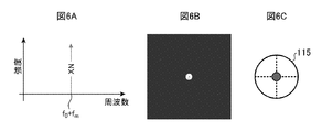
- 6A to 6C are diagrams showing an operation example in the CBC mode of the spatial optical communication apparatus according to Embodiment 1 of the present invention
- FIG. 6A is a diagram showing an example of an optical spectrum
- FIG. FIG. 6C is a diagram illustrating an example of a pattern
- FIG. 6C is a diagram illustrating an example of a positional relationship between an angle sensor and received light.
- It is a figure which shows the structural example of the space optical communication apparatus which concerns on Embodiment 2 of this invention.
- 8A and 8B are diagrams showing examples of simulation results of the output light intensity in the spatial optical communication apparatus according to Embodiment 2 of the present invention
- FIG. 8A is a diagram showing a case where there are two signal lights.
- FIG. 8B is a diagram showing a case where there are three signal lights. It is a figure which shows the operation example in the CBC mode of the space optical communication apparatus which concerns on Embodiment 2 of this invention, and is a figure which shows an example of a distant pattern.
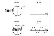
- 10A to 10D are diagrams showing an operation example in the ICBC mode of the spatial light communication apparatus according to Embodiment 2 of the present invention, and FIG. 10A is a diagram showing an example of the positional relationship between the angle sensor and the received light.
- 10B is a diagram illustrating an output example of the center of gravity calculation (before control), and FIG.
- FIG. 10C is a diagram illustrating an example of the positional relationship between the angle sensor and the received light (after control).
- 10D is a diagram (after control) showing an output example of the gravity center calculation.
- FIG. 11A is a diagram illustrating an arrangement example of a plurality of elements included in the optical phased array antenna according to Embodiment 3 of the present invention
- FIG. 11B is an image diagram illustrating an example of a temporal change in a peak position of a distant pattern.
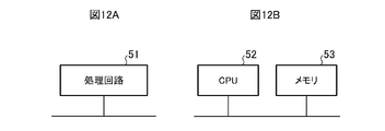
- 12A and 12B are diagrams showing a hardware configuration example of the signal processing unit in the first to third embodiments of the present invention.
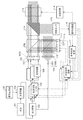
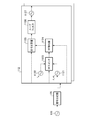
- FIG. 1 is a diagram showing a configuration example of a spatial light communication apparatus according to Embodiment 1 of the present invention.
- the spatial optical communication device is a phased array type spatial optical communication device that performs communication by outputting laser light to a space.
- the spatial optical communication apparatus includes a light source 101, a signal generation unit 102, an optical modulator 103, an optical distributor 104, n optical frequency shifters 105, n optical amplifiers 106, an optical phased array.
- n is an integer of 2 or more, and is the same number as the number of elements that the optical phased array antennas 107 and 111 have.
- the light source 101 emits laser light. Laser light emitted from the light source 101 is output to the optical modulator 103.
- the signal generator 102 generates a communication signal.
- the communication signal generated by the signal generation unit 102 is output to the optical modulator 103.
- the optical modulator 103 generates modulated light by superimposing the communication signal generated by the signal generator 102 on the laser light emitted from the light source 101.
- the optical modulator 103 for example, a Mach-Zehnder optical modulator is used.
- the modulated light generated by the optical modulator 103 is output to the optical distributor 104.
- the optical distributor 104 branches the modulated light generated by the optical modulator 103 into one local light and n signal lights.
- the optical distributor 104 for example, a polarization maintaining optical coupler is used.
- the local light obtained by the optical distributor 104 is output to the collimator 109, and the n signal lights obtained by the optical distributor 104 are distributed one by one to the n optical frequency shifters 105.
- the optical frequency shifter 105 adjusts the phase of the signal light distributed by the optical distributor 104 according to control by the phase control circuit 112.
- the signal light after the phase adjustment by the optical frequency shifter 105 is output to the optical amplifier 106 connected to the own device (optical frequency shifter 105).
- the n optical frequency shifters 105 constitute a “phase adjusting unit that adjusts the phase of each signal light obtained by the optical distributor 104”.
- the optical amplifier 106 amplifies the power of the signal light output from the optical frequency shifter 105 connected to the optical amplifier 106 (the optical amplifier 106).
- the optical amplifier 106 for example, an optical fiber amplifier or a semiconductor optical amplifier is used.
- the signal light amplified by the optical amplifier 106 is output to the optical phased array antenna 107.
- the n optical amplifiers 106 constitute “an optical amplification unit that amplifies each signal light after phase adjustment by the phase adjustment unit”.
- the optical phased array antenna 107 outputs the signal light output from each optical amplifier 106 to the space as collimated light.
- the optical phased array antenna 107 includes n collimators (elements) each including an optical fiber 1071 and a collimator lens 1072, and the n collimators are arranged in an array.
- One end of the optical fiber 1071 faces the output end of one optical amplifier 106, and the incident surface of the collimator lens 1072 faces the other end of the optical fiber 1071.
- the beam splitter 108 divides each of the n signal lights output from the optical phased array antenna 107 into two parts by transmitting a part of the incident light and reflecting the rest.
- the n signal lights that have passed through the beam splitter 108 are used for communication in the spatial light communication device. Further, the n signal lights reflected by the beam splitter 108 are used for phase error detection in the spatial light communication device.
- the collimator 109 outputs the local light output from the light distributor 104 to the space as collimated light.
- the collimator 109 includes an optical fiber 1091 having one end facing one of a plurality of output ends of the light distributor 104, and a collimator lens 1092 having an incident surface facing the other end of the optical fiber 1091.
- the beam splitter 110 transmits the n signal lights reflected by the beam splitter 108 and reflects the local light transmitted by the collimator 109, thereby combining the local light with the n signal lights. .
- the n signal lights combined with the local lights by the beam splitter 110 are output to the optical phased array antenna 111.
- the optical phased array antenna 111 receives n signal lights combined with local light emitted by the beam splitter 110.
- the optical phased array antenna 111 includes n collimators (elements) each including a collimator lens 1111 and a photodiode 1112, and the n collimators are arranged in an array.
- the collimator lens 1111 condenses one signal light combined with the local light by the beam splitter 110.
- the photodiode 1112 is an optical receiver that receives the signal light collected by the collimator lens 1111 and converts it into an electrical signal.
- a reception signal (electric signal) as a reception result by the optical phased array antenna 111 is output to each phase control circuit 112.
- the phase control circuit 112 is controlled by the signal processing unit 116 and the signal switching circuit 117, and based on the received signal output from the optical phased array antenna 111, the optical frequency shifter 105 connected to the own device (phase control circuit 112). Controls the amount of phase shift. At this time, the phase control circuit 112 detects the phase error between the reference signal and the received signal output from the optical phased array antenna 111, and outputs the phase error compensation signal for controlling the phase shift amount so as to eliminate this phase error. Output to the optical frequency shifter 105. Details of the phase control circuit 112 will be described later.
- the beam splitter 108, the collimator 109, the beam splitter 110, the optical phased array antenna 111, and the n phase control circuits 112 are “output by the optical phased array antenna 107 and controlled by the optical distributor 104 under the control of the phase adjustment unit. It constitutes a “phase control unit” that synchronizes each signal light combined with the obtained local light with a reference signal.
- the acquisition and tracking mechanism 113 adjusts the output angle (propagation angle) of n signal lights output from the optical phased array antenna 107 and transmitted through the wavelength separation splitter 114 according to control by the control circuit 118.
- an adaptive mirror is used as the capture and tracking mechanism 113.
- the wavelength separation splitter 114 is an optical path separation splitter that transmits the signal light that has passed through the beam splitter 108 and reflects received light that has arrived from the outside.
- the angle sensor 115 detects the arrival angle of the received light reflected by the wavelength separation splitter 114.
- a four-quadrant angle sensor is used as the angle sensor 115.
- a reception angle signal that is a detection result by the angle sensor 115 is output to the signal processing unit 116.
- the wavelength separation splitter 114 and the angle sensor 115 constitute an “angle detection unit that detects an arrival angle of received light that has arrived from the outside”.
- the signal processing unit 116 controls the phase control circuit 112, the signal switching circuit 117, and the control circuit 118 based on the detection result by the angle sensor 115. Details of the signal processing unit 116 will be described later.
- the signal switching circuit 117 switches the reference signal used in the phase control circuit 112 to the first reference signal or the second reference signal according to control by the signal processing unit 116.
- the first reference signal is a reference signal for capturing received light (initial capturing), and has a different frequency for each signal light. In the first embodiment, each first reference signal is set to a random frequency.
- the second reference signal is a communication reference signal and has the same frequency for each signal light.
- the control circuit 118 controls the capture and tracking mechanism 113 according to the control by the signal processing unit 116.
- the signal processing unit 116, the signal switching circuit 117, and the control circuit 118 indicate that “the reference signal used in the phase control unit is a plurality of first reference signals having different frequencies for each signal light, and is based on the detection result by the angle detection unit.
- the received light is supplemented by control of the acquisition and tracking mechanism 113, and after the acquisition is completed, the reference signal is set as a second reference signal having the same frequency as each signal light, and phase adjustment based on the detection result by the angle detection unit A control unit that performs tracking of the received light ”.
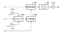
- the phase control circuit 112 includes a signal source 1121, a signal source 1122, an RF (Radio Frequency) switch 1123, an RF phase shifter 1124, a phase comparator 1125, a loop filter 1126, and a VCO (Voltage Controlled Oscillator). 1127.
- RF Radio Frequency
- the signal source 1121 generates a first reference signal.
- the first reference signal generated by the signal source 1121 is output to the RF switch 1123.
- the signal source 1122 generates a second reference signal.
- the second reference signal generated by the signal source 1122 is output to the RF switch 1123.
- the RF switch 1123 controls the RF phase shifter 1124 with one of the first reference signal output from the signal source 1121 and the second reference signal output from the signal source 1122 as a reference signal according to control by the signal switching circuit 117. Output.
- the RF phase shifter 1124 adjusts the phase of the reference signal output by the RF switch 1123 according to the control by the signal processing unit 116.
- the reference signal after the phase adjustment by the RF phase shifter 1124 is output to the phase comparator 1125.
- the phase comparator 1125 detects a phase error between the reference signal output from the RF phase shifter 1124 and the received signal output from the optical phased array antenna 111.
- a phase comparison signal that is a comparison result by the phase comparator 1125 is output to the loop filter 1126.
- the loop filter 1126 smoothes the phase comparison signal output from the phase comparator 1125.
- the phase comparison signal smoothed by the loop filter 1126 is output to the VCO 1127.
- the VCO 1127 Based on the phase comparison signal output from the loop filter 1126, the VCO 1127 generates a high-frequency signal for making the reception signal output from the optical phased array antenna 111 equal to the frequency of the reference signal output from the RF phase shifter 1124. Generate.
- the phase error compensation signal which is a high frequency signal generated by the VCO 1127, is output to the optical frequency shifter 105.
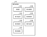
- the signal processing unit 116 includes a synchronization unit 1161, a first switching unit 1162, a first determination unit 1163, a first control unit 1164, a second switching unit 1165, a second determination unit 1166, and a second control. Part 1167.
- the synchronization unit 1161 controls the signal switching circuit 117 to synchronize each signal light with the frequency of the second reference signal.
- the first switching unit 1162 synchronizes each signal light with the frequency of the first reference signal by controlling the signal switching circuit 117 after the processing by the synchronization unit 1161 is completed.
- the first determination unit 1163 determines whether the detection result (the incoming angle of the received light) by the angle sensor 115 is within the first threshold after the processing by the first switching unit 1162 is completed.
- the first threshold is a value within a range in which the angle sensor 115 can detect the arrival angle of the received light.
- the first control unit 1164 controls the control circuit 118 to determine the arrival angle of the received light. Move towards the center of the.
- the second switching unit 1165 controls the signal switching circuit 117 to set each signal light to the second reference signal. Synchronize with the frequency.
- the second determination unit 1166 determines whether the detection result (the incoming angle of the received light) by the angle sensor 115 is within the second threshold after the processing by the second switching unit 1165 is completed.
- the second threshold value is a value within a range narrower than the first threshold value.
- the second control unit 1167 controls the RF phase shifter 1124 included in the phase control circuit 112 when the second determination unit 1166 determines that the arrival angle of the received light is not within the second threshold value.
- the light arrival angle is moved toward the center of the angle sensor 115.
- the light source 101 emits laser light
- the signal generation unit 102 generates a communication signal.
- the center frequency of the laser light emitted from the light source 101 is f 0 .
- the optical modulator 103 generates modulated light by superimposing the communication signal generated by the signal generator 102 on the laser light emitted from the light source 101.
- the optical distributor 104 branches the modulated light generated by the optical modulator 103 into one local light and n signal lights.
- the phase adjustment unit (n optical frequency shifters 105) adjusts the phase of the n signal lights obtained by the optical distributor 104.
- the optical amplification unit (n optical amplifiers 106) amplifies the n signal lights after the phase adjustment by the phase adjustment unit.
- the optical phased array antenna 107 outputs n signal lights amplified by the optical amplification unit to the space.
- the phase control unit (beam splitter 108, collimator 109, beam splitter 110, optical phased array antenna 111, and n phase control circuits 112) is output from the optical phased array antenna 107 and obtained by the optical distributor 104.
- the n signal lights combined with the local light are synchronized with the reference signal.
- the acquisition and tracking mechanism 113 adjusts the output angles of the n signal lights output from the optical phased array antenna 107.
- the angle detection unit (the wavelength separation splitter 114 and the angle sensor 115) detects the arrival angle of the received light coming from the outside. The detection result by the angle detection unit is notified to the signal processing unit 116, and the signal processing unit 116 captures and tracks the received light.
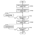
- the synchronization unit 1161 controls the signal switching circuit 117 to synchronize the n signal lights with the frequency of the second reference signal (step) ST401). That is, since the phase of n signal lights changes randomly depending on the optical path, the synchronization unit 1161 compensates for this phase fluctuation.
- the signal switching circuit 117 causes the reference signal used in each phase control circuit 112 to be the second reference signal in accordance with control by the synchronization unit 1161.
- the second reference signal is the same frequency for n of the signal light, the center frequency and f m.
- the spatial light communication apparatus performs the overall operation described above. As a result, the spatial light communication apparatus compensates for the phase error between the signal lights and makes the frequency and phase of the n signal lights the same.
- the first switching unit 1162 controls the signal switching circuit 117 to synchronize each signal light with the frequency of the first reference signal (step ST402).
- the operation mode of the spatial light communication device is set to the initial acquisition mode (ICBC mode).
- the signal switching circuit 117 causes the reference signal used in each phase control circuit 112 to be the first reference signal in accordance with the control by the first switching unit 1162.
- the first reference signal has a different frequency for each signal light, and the center frequency thereof is (f m + f n ).
- the optical spectrum of the output light from the optical phased array antenna 107 is shown in FIG. 5A.
- each phase control circuit 112 of the first embodiment the difference between adjacent frequencies of each first reference signal is set randomly so as not to be constant.
- the received light input to the angle sensor 115 of the spatial optical communication apparatus that is the communication partner becomes incoherent combination (ICBC) of n signal lights, and has a beam spread like a distant pattern shown in FIG. 5B. Light.
- ICBC incoherent combination
- the spatial light communication apparatus performs the overall operation described above, and starts supplementing received light (initial capture).
- first determination section 1163 determines whether the detection result (angle of arrival of received light) by angle sensor 115 is within the first threshold (step ST403).
- the first determination unit 1163 roughly determines the stability of signal light transmission and reception.
- the first control unit 1164 controls the control circuit 118 to control the received light.
- the arrival angle is moved toward the center of the angle sensor 115 (step ST404).
- FIG. 5C shows an example of the positional relationship between the angle sensor 115 and the received light. Thereafter, the sequence returns to step ST403.
- the second switching unit 1165 controls the signal switching circuit 117 to The signal light is synchronized with the frequency of the second reference signal (step ST405).
- the operation mode of the spatial light communication device is the tracking mode (CBC mode).
- the signal switching circuit 117 causes the reference signal used in each phase control circuit 112 to be the second reference signal according to the control by the second switching unit 1165.
- the optical spectrum of the output light from the optical phased array antenna 107 is shown in FIG. 6A.
- the received light input to the angle sensor 115 of the spatial light communication apparatus that is the communication partner is light having a sharp beam size with respect to the far pattern shown in FIG. 5B, like the far pattern shown in FIG. 6B. Therefore, the angle sensor 115 can detect the angle with high accuracy as compared with the case of capturing the received light.
- second determination section 1166 determines whether or not the detection result (angle of arrival of received light) by angle sensor 115 is within the second threshold (step ST406).
- the second determination unit 1166 determines the stability of signal light transmission and reception with high accuracy.
- the second control unit 1167 controls the phase control circuit 112 to receive the received light. Is moved toward the center of the angle sensor 115 (step ST407).
- FIG. 6C shows an example of the positional relationship between the angle sensor 115 and the received light. Thereafter, the sequence returns to step ST406.
- the signal processing unit 116 ends the sequence assuming that the tracking of the received light is completed. Thereafter, the spatial optical communication device starts optical communication with the spatial optical communication device that is the communication partner.
- the spatial optical communication device includes the optical distributor 104 that branches the modulated light into the local light and the plurality of signal lights, and each signal light obtained by the optical distributor 104.
- a phase adjustment unit that adjusts the phase
- an optical amplification unit that amplifies each signal light after phase adjustment by the phase adjustment unit
- an optical phased array antenna 107 that outputs each signal light amplified by the optical amplification unit to space
- a phase control unit that synchronizes each signal light, which is output from the optical phased array antenna 107 and obtained by the optical distributor 104 and combined with the local light, by a control of the phase adjustment unit with a reference signal, and an optical phased array antenna 107
- a capture and tracking mechanism 113 that adjusts the output angle of each signal light output from the signal 107
- an angle detection unit that detects the arrival angle of received light that has arrived from the outside, and a reference signal used in the phase control unit.
- the received light is supplemented by control of the acquisition and tracking mechanism 113 based on the detection result by the angle detection unit, and after the acquisition is completed, the reference signal is used as each signal light.
- a control unit for tracking the received light by controlling the phase adjustment unit based on the detection result by the angle detection unit.
- FIG. 7 is a diagram showing a configuration example of a spatial optical communication apparatus according to Embodiment 2 of the present invention.
- the spatial optical communication apparatus according to the second embodiment shown in FIG. 7 has a signal source 119 and a signal distributor 120 added to the spatial optical communication apparatus according to the first embodiment shown in FIG.
- FIG. 7 illustrates only the signal source 119, the signal distributor 120, and each phase control circuit 112 in the spatial optical communication apparatus according to the second embodiment.
- Other configurations of the spatial optical communication apparatus according to the second embodiment are the same as those of the spatial optical communication apparatus according to the first embodiment shown in FIG. 1, and only different parts will be described.
- the signal source 119 generates a third reference signal.
- the third reference signal is a reference signal for synchronizing each first reference signal.
- the third reference signal generated by the signal source 119 is output to the signal distributor 120.
- the signal distributor 120 branches the third reference signal generated by the signal source 119 into n pieces.
- the n third reference signals obtained by the signal distributor 120 are distributed one by one to the signal sources 1121 included in the n phase control circuits 112.
- the signal source 1121 generates a first reference signal synchronized with the third reference signal obtained by the signal distributor 120.
- the difference between adjacent frequencies is set to be constant for each first reference signal.
- the first determination unit 1163 performs a centroid operation on the detection result (arrival angle of received light) by the angle sensor 115, and the average value of the centroid operation is the first value. It is determined whether it is within one threshold.
- the first control unit 1164 controls the control circuit 118 to obtain the average value of the center of gravity calculation. It is moved toward the center of the angle sensor 115.
- the phase difference of each signal light periodically changes according to the difference in frequency.
- the phase difference of each signal light vibrates in the range of ⁇ ⁇ at 10 MHz.
- FIG. 8B shows a case where the spatial optical communication apparatus uses three signal lights and the frequency difference is 10 MHz.
- phased array type spatial optical communication apparatus that captures received light in a beaconless manner by performing beam scanning by electronically controlling the phase of each signal light.
- the scan rate is limited by the loop bandwidth of the PLL (Phase Locked Loop).
- the spatial light communication device when capturing received light, the frequency difference of each signal light is made constant so that the phase of each signal light is not electrically controlled. , Sweep.
- the spatial optical communication apparatus is not limited to the loop bandwidth of the PLL, and can perform high-speed beam scanning in the MHz band or higher.
- the difference between adjacent frequencies of the first reference signals is equal to or less than the reception band of the angle sensor 115.
- f d is several tens of MHz to several GHz when the angle sensor 115 is a four-quadrant photodiode.
- the scan rate is limited to the loop bandwidth of the PLL of less than 100 kHz.
- FIG. 9 shows a temporal change of the far pattern when the spatial light communication apparatus uses four signal lights.
- each signal light is instantaneously coherently combined with the supplement of the received light in the first embodiment, so that the peak intensity is the number of signal lights. Only increase.
- a received signal having a certain width as shown in FIG. 10B is obtained.
- the signal processing unit 116 controls the acquisition and tracking mechanism 113 so that the average value of the center of gravity calculation of the received signal approaches the center of the angle sensor 115 so that the average value is within the first threshold (see FIG. 10A to FIG. 10D).
- the subsequent processing is the same as in the first embodiment.
- the present invention is not limited to this, and a plurality of elements included in the optical phased array antenna 107 may be two-dimensionally arranged.
- the first reference signals used in the phase control unit are synchronized with each other, and the difference between adjacent frequencies is constant.
- the spatial optical communication apparatus according to the second embodiment is 10 times faster than the conventional beam scan rate in which the phase of each signal light is electronically controlled in analog in addition to the effects of the first embodiment. Beam scanning can be realized.
- Embodiment 3 In the spatial optical communication apparatus according to the second embodiment, the case where a plurality of elements included in the optical phased array antenna 107 is one-dimensionally arranged or two-dimensionally arranged is shown.
- a plurality of elements included in the optical phased array antenna 107 are arranged in a triangle, and each first reference signal has a frequency spirally with respect to the plurality of elements. The case where it becomes large is shown.
- the configuration example of the spatial optical communication apparatus according to Embodiment 3 is the same as the configuration example of the spatial optical communication apparatus according to Embodiment 2 shown in FIG.
- FIG. 11A shows an arrangement example of a plurality of elements included in the optical phased array antenna 107
- FIG. 11B shows an example of a time change of a peak position in a distant pattern by arrows.
- Reference signs f 0 to f 18 in FIG. 11A indicate the frequency of the signal light for each element.
- the plurality of elements included in the optical phased array antenna 107 are arranged in a triangular arrangement as shown in FIG. 11A, and the frequency of each first reference signal corresponding to each element is expressed by the following formula ( 4).
- f i is the frequency of the i-th first reference signal
- f i-1 is the frequency of the i-1th first reference signal.
- f i f i ⁇ 1 + ⁇ f (4)
- the distant pattern is scanned in a spiral shape (spiral shape) at a rate of 2 ⁇ f.
- the spatial light communication apparatus according to Embodiment 3 can capture received light without omission of scanning by performing a spiral scan.
- the functions of the synchronization unit 1161, the first switching unit 1162, the first determination unit 1163, the first control unit 1164, the second switching unit 1165, the second determination unit 1166, and the second control unit 1167 in the signal processing unit 116 are processing. This is realized by the circuit 51.
- the processing circuit 51 may be dedicated hardware as shown in FIG. 12A, or as shown in FIG.
- a CPU Central Processing Unit
- a central processing unit It may be a processing device, an arithmetic device, a microprocessor, a microcomputer, a processor, or a DSP (Digital Signal Processor)) 52.
- the processing circuit 51 may be, for example, a single circuit, a composite circuit, a programmed processor, a parallel programmed processor, an ASIC (Application Specific Integrated Circuit), or an FPGA (Field Programmable Gate). Array) or a combination thereof.
- the processing circuit 51 implements the functions of the synchronization unit 1161, the first switching unit 1162, the first determination unit 1163, the first control unit 1164, the second switching unit 1165, the second determination unit 1166, and the second control unit 1167. Alternatively, the functions of the respective units may be integrated and realized by the processing circuit 51.
- the processing circuit 51 When the processing circuit 51 is the CPU 52, the functions of the synchronization unit 1161, the first switching unit 1162, the first determination unit 1163, the first control unit 1164, the second switching unit 1165, the second determination unit 1166, and the second control unit 1167 are as follows. , Software, firmware, or a combination of software and firmware. Software and firmware are described as programs and stored in the memory 53.
- the processing circuit 51 implements the functions of each unit by reading and executing the program stored in the memory 53. That is, the signal processing unit 116 includes a memory 53 for storing a program that, when executed by the processing circuit 51, for example, causes each step shown in FIG. 4 to be executed as a result.
- these programs are the procedures and methods of the synchronization unit 1161, the first switching unit 1162, the first determination unit 1163, the first control unit 1164, the second switching unit 1165, the second determination unit 1166, and the second control unit 1167. It can be said that it is what makes a computer execute.
- the memory 53 for example, a nonvolatile or volatile semiconductor memory such as a RAM (Random Access Memory), a ROM (Read Only Memory), a flash memory, an EPROM (Erasable Programmable ROM), an EEPROM (Electrically EPROM), or the like.
- a magnetic disk, a flexible disk, an optical disk, a compact disk, a mini disk, a DVD (Digital Versatile Disc), or the like is applicable.
- a part of each function of the synchronization unit 1161, the first switching unit 1162, the first determination unit 1163, the first control unit 1164, the second switching unit 1165, the second determination unit 1166, and the second control unit 1167 is dedicated. It may be realized by hardware of the above, and a part may be realized by software or firmware.
- the function of the synchronization unit 1161 is realized by the processing circuit 51 as dedicated hardware, and the first switching unit 1162, the first determination unit 1163, the first control unit 1164, the second switching unit 1165, and the second determination.
- the functions of the unit 1166 and the second control unit 1167 can be realized by the processing circuit 51 reading and executing the program stored in the memory 53.
- the processing circuit 51 can realize the above-described functions by hardware, software, firmware, or a combination thereof.
- the spatial optical communication apparatus can output communication light and beacon light using a single optical antenna, and is suitable for use in a spatial optical communication apparatus that performs communication by outputting laser light to space. Yes.
Landscapes
- Physics & Mathematics (AREA)
- Electromagnetism (AREA)
- Engineering & Computer Science (AREA)
- Computer Networks & Wireless Communication (AREA)
- Signal Processing (AREA)
- Astronomy & Astrophysics (AREA)
- General Physics & Mathematics (AREA)
- Optical Communication System (AREA)
- Variable-Direction Aerials And Aerial Arrays (AREA)
- Radio Transmission System (AREA)
Abstract
変調光を局発光及び複数の信号光に分岐する光分配器(104)と、光分配器(104)により得られた各信号光を位相調整する位相調整部と、位相調整部による位相調整後の各信号光を増幅する光増幅部と、光増幅部による増幅後の各信号光を空間に出力する光フェーズドアレイアンテナ(107)と、位相調整部の制御により、光フェーズドアレイアンテナ(107)により出力されて光分配器(104)により得られた局発光が合波された各信号光を、基準信号に同期させる位相制御部と、光フェーズドアレイアンテナ(107)により出力された各信号光の出力角度を調整する捕捉追尾機構(113)と、外部から到来した受信光の到来角を検出する角度検出部と、位相制御部で用いられる基準信号を信号光毎に周波数が異なる複数の第1基準信号とし、角度検出部による検出結果に基づく捕捉追尾機構(113)の制御により受信光の補足を行い、捕捉の完了後、当該基準信号を各信号光に対して周波数が同一である第2基準信号とし、角度検出部による検出結果に基づく位相調整部の制御により受信光の追尾を行う制御部とを備えた。
Description
この発明は、空間にレーザ光を出力して通信を行う空間光通信装置に関する。
空間光通信装置は、一般的なマイクロ波を用いて通信を行うマイクロ波通信装置に対し、小型且つ可搬性に優れ、ビームの広がりが小さく秘匿性を有し、電波法による制限を受けず、また、広い周波数帯域を利用可能であり高速な通信が可能といった利点がある。
一方、空間光通信装置は、ビームの広がりが小さいことから、通信を確立及び維持するために、通信相手から到来する受信光を捕捉し、送信光の出力角度を制御する必要がある。
これに対し、通信光とは別に高出力且つ広角であるビーコン光を出力して受信光の初期補足を行う空間光通信装置が知られている(例えば特許文献1参照)。
しかしながら、ビーコン光を用いる方式では、空間光通信装置が、送信光を出力する光源及び光アンテナとは別に、ビーコン光を出力する光源及び光アンテナを有する必要がある。よって、ビーコン光を用いる方式では、空間光通信装置が大型化し、また、空間光通信装置の消費電力が増大するといった課題がある。
この発明は、上記のような課題を解決するためになされたもので、単一の光アンテナを用いて通信光及びビーコン光を出力可能な空間光通信装置を提供することを目的としている。
この発明に係る空間光通信装置は、変調光を局発光及び複数の信号光に分岐する光分配器と、光分配器により得られた各信号光を位相調整する位相調整部と、位相調整部による位相調整後の各信号光を増幅する光増幅部と、光増幅部による増幅後の各信号光を空間に出力する光フェーズドアレイアンテナと、位相調整部の制御により、光フェーズドアレイアンテナにより出力されて光分配器により得られた局発光が合波された各信号光を、基準信号に同期させる位相制御部と、光フェーズドアレイアンテナにより出力された各信号光の出力角度を調整する捕捉追尾機構と、外部から到来した受信光の到来角を検出する角度検出部と、位相制御部で用いられる基準信号を信号光毎に周波数が異なる複数の第1基準信号とし、角度検出部による検出結果に基づく捕捉追尾機構の制御により受信光の補足を行い、捕捉の完了後、当該基準信号を各信号光に対して周波数が同一である第2基準信号とし、角度検出部による検出結果に基づく位相調整部の制御により受信光の追尾を行う制御部とを備えたことを特徴とする。
この発明によれば、上記のように構成したので、単一の光アンテナを用いて通信光及びビーコン光を出力可能となる。
以下、この発明の実施の形態について図面を参照しながら詳細に説明する。
実施の形態1.
図1はこの発明の実施の形態1に係る空間光通信装置の構成例を示す図である。
空間光通信装置は、空間にレーザ光を出力して通信を行うフェーズドアレイ型の空間光通信装置である。この空間光通信装置は、図1に示すように、光源101、信号生成部102、光変調器103、光分配器104、n個の光周波数シフタ105、n個の光増幅器106、光フェーズドアレイアンテナ107、ビームスプリッタ108、コリメータ109、ビームスプリッタ110、光フェーズドアレイアンテナ111、n個の位相制御回路112、捕捉追尾機構113、波長分離スプリッタ114、角度センサ115、信号処理部116、信号切替回路117及び制御回路118を備えている。nは2以上の整数であり、光フェーズドアレイアンテナ107,111が有する素子の数と同数である。
光源101は、レーザ光を発光する。光源101により発光されたレーザ光は、光変調器103に出力される。
信号生成部102は、通信信号を生成する。信号生成部102により生成された通信信号は、光変調器103に出力される。
光変調器103は、光源101により発光されたレーザ光に信号生成部102により生成された通信信号を重畳して変調光を生成する。光変調器103としては、例えばマッハツェンダ型光変調器が用いられる。光変調器103により生成された変調光は、光分配器104に出力される。
光分配器104は、光変調器103により生成された変調光を1個の局発光とn個の信号光とに分岐する。光分配器104としては、例えば偏波保持光カプラが用いられる。光分配器104により得られた局発光はコリメータ109に出力され、光分配器104により得られたn個の信号光はn個の光周波数シフタ105に1つずつ分配される。
光周波数シフタ105は、位相制御回路112による制御に従い、光分配器104により分配された信号光を位相調整する。光周波数シフタ105による位相調整後の信号光は、自機(光周波数シフタ105)に接続された光増幅器106に出力される。
なお、n個の光周波数シフタ105は、「光分配器104により得られた各信号光を位相調整する位相調整部」を構成する。
なお、n個の光周波数シフタ105は、「光分配器104により得られた各信号光を位相調整する位相調整部」を構成する。
光増幅器106は、自機(光増幅器106)に接続された光周波数シフタ105により出力された信号光のパワーを増幅する。光増幅器106としては、例えば光ファイバ増幅器又は半導体光増幅器が用いられる。光増幅器106による増幅後の信号光は、光フェーズドアレイアンテナ107に出力される。
なお、n個の光増幅器106は、「位相調整部による位相調整後の各信号光を増幅する光増幅部」を構成する。
なお、n個の光増幅器106は、「位相調整部による位相調整後の各信号光を増幅する光増幅部」を構成する。
光フェーズドアレイアンテナ107は、各光増幅器106により出力された信号光をコリメート光として空間に出力する。光フェーズドアレイアンテナ107は、光ファイバ1071及びコリメータレンズ1072から成るコリメータ(素子)をn個有し、このn個のコリメータがアレイ状に配置されることで構成される。なお、光ファイバ1071の一端は1つの光増幅器106の出力端に対向し、コリメータレンズ1072の入射面は光ファイバ1071の他端に対向している。
ビームスプリッタ108は、入射光の一部を透過させて残りを反射することで、光フェーズドアレイアンテナ107により出力されたn個の信号光をそれぞれ2分岐する。ビームスプリッタ108を透過したn個の信号光は、空間光通信装置において通信用として用いられる。また、ビームスプリッタ108により反射されたn個の信号光は、空間光通信装置において位相誤差検出用として用いられる。
コリメータ109は、光分配器104により出力された局発光をコリメート光として空間に出力する。コリメータ109は、一端が光分配器104が有する複数の出力端のうちの1つに対向した光ファイバ1091と、入射面が光ファイバ1091の他端に対向したコリメータレンズ1092とから構成される。
ビームスプリッタ110は、ビームスプリッタ108により反射されたn個の信号光を透過させ、コリメータ109により送信された局発光を反射することで、n個の信号光に対して局発光をそれぞれ合波する。ビームスプリッタ110により局発光が合波されたn個の信号光は、光フェーズドアレイアンテナ111に出力される。
光フェーズドアレイアンテナ111は、ビームスプリッタ110により局発光が合波されたn個の信号光を受信する。光フェーズドアレイアンテナ111は、コリメータレンズ1111及びフォトダイオード1112から成るコリメータ(素子)をn個有し、このn個のコリメータがアレイ状に配置されることで構成される。なお、コリメータレンズ1111は、ビームスプリッタ110により局発光が合波された1つの信号光を集光する。また、フォトダイオード1112は、コリメータレンズ1111により集光された信号光を受信して電気信号に変換する光受信器である。光フェーズドアレイアンテナ111による受信結果である受信信号(電気信号)は、各位相制御回路112に出力される。
位相制御回路112は、信号処理部116及び信号切替回路117による制御に従い、光フェーズドアレイアンテナ111により出力された受信信号に基づいて、自機(位相制御回路112)に接続された光周波数シフタ105の位相シフト量を制御する。この際、位相制御回路112は、基準信号と光フェーズドアレイアンテナ111により出力された受信信号との位相誤差を検出し、この位相誤差を無くすように位相シフト量を制御する位相誤差補償信号を上記光周波数シフタ105に出力する。位相制御回路112の詳細については後述する。
なお、ビームスプリッタ108、コリメータ109、ビームスプリッタ110、光フェーズドアレイアンテナ111及びn個の位相制御回路112は、「位相調整部の制御により、光フェーズドアレイアンテナ107により出力されて光分配器104により得られた局発光が合波された各信号光を、基準信号に同期させる位相制御部」を構成する。
捕捉追尾機構113は、制御回路118による制御に従い、光フェーズドアレイアンテナ107により出力されて波長分離スプリッタ114を透過したn個の信号光の出力角度(伝搬角度)を調整する。捕捉追尾機構113としては、例えばアダプティブミラーが用いられる。
波長分離スプリッタ114は、ビームスプリッタ108を透過した信号光を透過させ、外部から到来した受信光を反射する光路分離スプリッタである。
角度センサ115は、波長分離スプリッタ114により反射された受信光の到来角を検出する。角度センサ115としては、例えば4象限角度センサが用いられる。角度センサ115による検出結果である受信角信号は、信号処理部116に出力される。
なお、波長分離スプリッタ114及び角度センサ115は、「外部から到来した受信光の到来角を検出する角度検出部」を構成する。
信号処理部116は、角度センサ115による検出結果に基づいて、位相制御回路112、信号切替回路117及び制御回路118を制御する。信号処理部116の詳細については後述する。
信号切替回路117は、信号処理部116による制御に従い、位相制御回路112で用いられる基準信号を第1基準信号又は第2基準信号に切替える。第1基準信号は、受信光の捕捉(初期捕捉)用の基準信号であり、信号光毎に周波数が異なる。実施の形態1では、各第1基準信号は、ランダムな周波数に設定されている。第2基準信号は、通信用の基準信号であり、各信号光に対して周波数が同一である。
制御回路118は、信号処理部116による制御に従い、捕捉追尾機構113を制御する。
なお、信号処理部116、信号切替回路117及び制御回路118は、「位相制御部で用いられる基準信号を信号光毎に周波数が異なる複数の第1基準信号とし、角度検出部による検出結果に基づく捕捉追尾機構113の制御により受信光の補足を行い、捕捉の完了後、当該基準信号を各信号光に対して周波数が同一である第2基準信号とし、角度検出部による検出結果に基づく位相調整部の制御により受信光の追尾を行う制御部」を構成する。
次に、位相制御回路112の構成例について、図2を参照しながら説明する。
位相制御回路112は、図2に示すように、信号源1121、信号源1122、RF(Radio Frequency)スイッチ1123、RF移相器1124、位相比較器1125、ループフィルタ1126及びVCO(Voltage Controlled Oscillator)1127を有している。
位相制御回路112は、図2に示すように、信号源1121、信号源1122、RF(Radio Frequency)スイッチ1123、RF移相器1124、位相比較器1125、ループフィルタ1126及びVCO(Voltage Controlled Oscillator)1127を有している。
信号源1121は、第1基準信号を生成する。信号源1121により生成された第1基準信号は、RFスイッチ1123に出力される。
信号源1122は、第2基準信号を生成する。信号源1122により生成された第2基準信号は、RFスイッチ1123に出力される。
RFスイッチ1123は、信号切替回路117による制御に従い、信号源1121により出力された第1基準信号又は信号源1122により出力された第2基準信号のうちの一方を基準信号としてRF移相器1124に出力する。
RF移相器1124は、信号処理部116による制御に従い、RFスイッチ1123により出力された基準信号を位相調整する。RF移相器1124による位相調整後の基準信号は、位相比較器1125に出力される。
位相比較器1125は、RF移相器1124により出力された基準信号と、光フェーズドアレイアンテナ111により出力された受信信号との位相誤差を検出する。位相比較器1125による比較結果である位相比較信号は、ループフィルタ1126に出力される。
ループフィルタ1126は、位相比較器1125により出力された位相比較信号を平滑する。ループフィルタ1126による平滑後の位相比較信号は、VCO1127に出力される。
VCO1127は、ループフィルタ1126により出力された位相比較信号に基づいて、光フェーズドアレイアンテナ111により出力された受信信号をRF移相器1124により出力された基準信号の周波数と等しくするための高周波信号を生成する。このVCO1127により生成された高周波信号である位相誤差補償信号は、光周波数シフタ105に出力される。
次に、信号処理部116の構成例について、図3を参照しながら説明する。
信号処理部116は、図3に示すように、同期部1161、第1切替部1162、第1判定部1163、第1制御部1164、第2切替部1165、第2判定部1166及び第2制御部1167を有している。
信号処理部116は、図3に示すように、同期部1161、第1切替部1162、第1判定部1163、第1制御部1164、第2切替部1165、第2判定部1166及び第2制御部1167を有している。
同期部1161は、信号切替回路117を制御することで、各信号光を第2基準信号の周波数に同期させる。
第1切替部1162は、同期部1161による処理が完了した後、信号切替回路117を制御することで、各信号光を第1基準信号の周波数に同期させる。
第1判定部1163は、第1切替部1162による処理が完了した後、角度センサ115による検出結果(受信光の到来角)が第1閾値内であるかを判定する。第1閾値は、角度センサ115において受信光の到来角を検出可能な範囲内の値である。
第1制御部1164は、第1判定部1163により受信光の到来角が第1閾値内ではないと判定された場合に、制御回路118を制御することで、受信光の到来角を角度センサ115の中心に向けて移動させる。
第2切替部1165は、第1判定部1163により受信光の到来角が第1閾値内であると判定された場合に、信号切替回路117を制御することで、各信号光を第2基準信号の周波数に同期させる。
第2判定部1166は、第2切替部1165による処理が完了した後、角度センサ115による検出結果(受信光の到来角)が第2閾値内であるかを判定する。第2閾値は、第1閾値よりも狭い範囲内の値である。
第2制御部1167は、第2判定部1166により受信光の到来角が第2閾値内ではないと判定された場合に、位相制御回路112が有するRF移相器1124を制御することで、受信光の到来角を角度センサ115の中心に向けて移動させる。
次に、実施の形態1に係る空間光通信装置の全体動作例について、図1を参照しながら説明する。
空間光通信装置の全体動作例では、まず、光源101はレーザ光を発光し、また、信号生成部102は通信信号を生成する。なお、光源101が発光するレーザ光の中心周波数をf0とする。
次いで、光変調器103は、光源101により発光されたレーザ光に信号生成部102により生成された通信信号を重畳して変調光を生成する。
空間光通信装置の全体動作例では、まず、光源101はレーザ光を発光し、また、信号生成部102は通信信号を生成する。なお、光源101が発光するレーザ光の中心周波数をf0とする。
次いで、光変調器103は、光源101により発光されたレーザ光に信号生成部102により生成された通信信号を重畳して変調光を生成する。
次いで、光分配器104は、光変調器103により生成された変調光を1個の局発光及びn個の信号光に分岐する。
次いで、位相調整部(n個の光周波数シフタ105)は、光分配器104により得られたn個の信号光を位相調整する。
次いで、光増幅部(n個の光増幅器106)は、位相調整部による位相調整後のn個の信号光を増幅する。
次いで、位相調整部(n個の光周波数シフタ105)は、光分配器104により得られたn個の信号光を位相調整する。
次いで、光増幅部(n個の光増幅器106)は、位相調整部による位相調整後のn個の信号光を増幅する。
次いで、光フェーズドアレイアンテナ107は、光増幅部による増幅後のn個の信号光を空間に出力する。
また、位相制御部(ビームスプリッタ108、コリメータ109、ビームスプリッタ110、光フェーズドアレイアンテナ111及びn個の位相制御回路112)は、光フェーズドアレイアンテナ107により出力されて光分配器104により得られた局発光が合波されたn個の信号光を、基準信号に同期させる。
また、捕捉追尾機構113は、光フェーズドアレイアンテナ107により出力されたn個の信号光の出力角度を調整する。
また、角度検出部(波長分離スプリッタ114及び角度センサ115)は、外部から到来した受信光の到来角を検出する。この角度検出部による検出結果は信号処理部116に通知され、信号処理部116は受信光の捕捉及び追尾を実施する。
次に、実施の形態1における信号処理部116の動作例について、図4を参照しながら説明する。
信号処理部116の動作例では、図4に示すように、まず、同期部1161は、信号切替回路117を制御することで、n個の信号光を第2基準信号の周波数に同期させる(ステップST401)。すなわち、n個の信号光は光路によって位相がランダムに変化するため、同期部1161はこの位相変動を補償する。この際、信号切替回路117は、同期部1161による制御に従い、各位相制御回路112で用いられる基準信号を第2基準信号とさせる。第2基準信号はn個の信号光に対して同一の周波数であり、その中心周波数をfmとする。その後、空間光通信装置は、上記に示した全体動作を行う。これにより、空間光通信装置は、信号光間の位相誤差を補償し、n個の信号光の周波数及び位相を同一とする。
信号処理部116の動作例では、図4に示すように、まず、同期部1161は、信号切替回路117を制御することで、n個の信号光を第2基準信号の周波数に同期させる(ステップST401)。すなわち、n個の信号光は光路によって位相がランダムに変化するため、同期部1161はこの位相変動を補償する。この際、信号切替回路117は、同期部1161による制御に従い、各位相制御回路112で用いられる基準信号を第2基準信号とさせる。第2基準信号はn個の信号光に対して同一の周波数であり、その中心周波数をfmとする。その後、空間光通信装置は、上記に示した全体動作を行う。これにより、空間光通信装置は、信号光間の位相誤差を補償し、n個の信号光の周波数及び位相を同一とする。
次いで、第1切替部1162は、信号切替回路117を制御することで、各信号光を第1基準信号の周波数に同期させる(ステップST402)。この第1切替部1162の動作により、空間光通信装置は、動作モードが初期捕捉モード(ICBCモード)となる。この際、信号切替回路117は、第1切替部1162による制御に従い、各位相制御回路112で用いられる基準信号を第1基準信号とさせる。第1基準信号は信号光毎に異なる周波数であり、その中心周波数を(fm+fn)とする。光フェーズドアレイアンテナ107による出力光の光スペクトルを図5Aに示す。また、角度センサ115の受信帯域をfdとした場合、次式(1),(2)のように、各第1基準信号の隣り合う周波数の差は角度センサ115における受信帯域以上となっている。式(1),(2)において、Δfiは、i+1番目の第1基準信号の周波数であるfi+1とi番目の第1基準信号の周波数であるfiとの差である。
fd<Δfi (1)
Δfi=fi+1-fi (2)
fd<Δfi (1)
Δfi=fi+1-fi (2)
更に、実施の形態1の各位相制御回路112では、各第1基準信号の隣り合う周波数の差が一定とならないようにランダムに設定されている。これにより、通信相手である空間光通信装置の角度センサ115に入力される受信光は、n個の信号光のインコヒーレント合成(ICBC)となり、図5Bに示す遠方パターンのようにビーム広がりを持った光となる。
その後、空間光通信装置は、上記に示した全体動作を行い、受信光の補足(初期捕捉)を開始する。
次いで、第1判定部1163は、角度センサ115による検出結果(受信光の到来角)が第1閾値内であるかを判定する(ステップST403)。この第1判定部1163により、信号光の送受信の安定性を粗く判定する。
このステップST403において、第1判定部1163が角度センサ115による検出結果が第1閾値内ではないと判定した場合には、第1制御部1164は、制御回路118を制御することで、受信光の到来角を角度センサ115の中心に向けて移動させる(ステップST404)。図5Cに角度センサ115と受信光との位置関係の一例を示す。その後、シーケンスはステップST403に戻る。
このステップST403において、第1判定部1163が角度センサ115による検出結果が第1閾値内ではないと判定した場合には、第1制御部1164は、制御回路118を制御することで、受信光の到来角を角度センサ115の中心に向けて移動させる(ステップST404)。図5Cに角度センサ115と受信光との位置関係の一例を示す。その後、シーケンスはステップST403に戻る。
一方、ステップST403において、第1判定部1163が角度センサ115による検出結果が第1閾値内であると判定した場合には、第2切替部1165は、信号切替回路117を制御することで、各信号光を第2基準信号の周波数に同期させる(ステップST405)。この第2切替部1165の動作により、空間光通信装置は、動作モードが追尾モード(CBCモード)となる。この際、信号切替回路117は、第2切替部1165による制御に従い、各位相制御回路112で用いられる基準信号を第2基準信号とさせる。光フェーズドアレイアンテナ107による出力光の光スペクトルを図6Aに示す。また、通信相手である空間光通信装置の角度センサ115に入力される受信光は、図6Bに示す遠方パターンのように、図5Bに示す遠方パターンに対してシャープなビームサイズの光となる。よって、角度センサ115は、受信光の捕捉の場合に対し、高精度な角度検出が可能となる。
次いで、第2判定部1166は、角度センサ115による検出結果(受信光の到来角)が第2閾値内であるかを判定する(ステップST406)。この第2判定部1166により、信号光の送受信の安定性を高精度に判定する。
このステップST406において、第2判定部1166が角度センサ115による検出結果が第2閾値内ではないと判定した場合には、第2制御部1167は、位相制御回路112を制御することで、受信光の到来角を角度センサ115の中心に向けて移動させる(ステップST407)。図6Cに角度センサ115と受信光との位置関係の一例を示す。その後、シーケンスはステップST406に戻る。
このステップST406において、第2判定部1166が角度センサ115による検出結果が第2閾値内ではないと判定した場合には、第2制御部1167は、位相制御回路112を制御することで、受信光の到来角を角度センサ115の中心に向けて移動させる(ステップST407)。図6Cに角度センサ115と受信光との位置関係の一例を示す。その後、シーケンスはステップST406に戻る。
一方、ステップST406において、第2判定部1166が角度センサ115による検出結果が第2閾値内であると判定した場合には、信号処理部116は受信光の追尾が完了したとしてシーケンスを終了する。その後、空間光通信装置は、通信相手である空間光通信装置との間で光通信を開始する。
以上のように、この実施の形態1によれば、空間光通信装置は、変調光を局発光及び複数の信号光に分岐する光分配器104と、光分配器104により得られた各信号光を位相調整する位相調整部と、位相調整部による位相調整後の各信号光を増幅する光増幅部と、光増幅部による増幅後の各信号光を空間に出力する光フェーズドアレイアンテナ107と、位相調整部の制御により、光フェーズドアレイアンテナ107により出力されて光分配器104により得られた局発光が合波された各信号光を、基準信号に同期させる位相制御部と、光フェーズドアレイアンテナ107により出力された各信号光の出力角度を調整する捕捉追尾機構113と、外部から到来した受信光の到来角を検出する角度検出部と、位相制御部で用いられる基準信号を信号光毎に周波数が異なる複数の第1基準信号とし、角度検出部による検出結果に基づく捕捉追尾機構113の制御により受信光の補足を行い、捕捉の完了後、当該基準信号を各信号光に対して周波数が同一である第2基準信号とし、角度検出部による検出結果に基づく位相調整部の制御により受信光の追尾を行う制御部とを備えた。これにより、実施の形態1に係る空間光通信装置は、単一の光アンテナ(光フェーズドアレイアンテナ107)を用いて通信光及びビーコン光を時間的に切替えて出力可能となり、ビーコンレスで受信光の捕捉が実現可能となり、空間光通信の安定化が実現可能となる。
実施の形態2.
実施の形態1に係る空間光通信装置では、各信号光に対して周波数差がランダムな周波数シフトを付加することで、ビーム広がりを持ったインコヒーレント合成光をビーコン光として用いる場合を示した。これに対し、実施の形態2に係る空間光通信装置では、各信号光に周波数差が一定の周波数シフトを付加することで、コヒーレント合成されたシャープな光を高速にスキャンする場合を示す。
図7はこの発明の実施の形態2に係る空間光通信装置の構成例を示す図である。図7に示す実施の形態2に係る空間光通信装置は、図1に示す実施の形態1に係る空間光通信装置に対し、信号源119及び信号分配器120を追加している。なお図7では、実施の形態2に係る空間光通信装置のうち、信号源119及び信号分配器120と各位相制御回路112のみを図示している。実施の形態2に係る空間光通信装置のその他の構成は図1に示す実施の形態1に係る空間光通信装置と同様であり、異なる部分についてのみ説明を行う。
信号源119は、第3基準信号を生成する。第3基準信号は、各第1基準信号を同期させるための基準信号である。信号源119により生成された第3基準信号は、信号分配器120に出力される。
信号分配器120は、信号源119により生成された第3基準信号をn個に分岐する。信号分配器120により得られたn個の第3の基準信号はn個の位相制御回路112が有する信号源1121に1つずつ分配される。
信号分配器120は、信号源119により生成された第3基準信号をn個に分岐する。信号分配器120により得られたn個の第3の基準信号はn個の位相制御回路112が有する信号源1121に1つずつ分配される。
なお、信号源1121は、信号分配器120により得られた第3基準信号に同期した第1基準信号を生成する。実施の形態2では、各第1基準信号は、隣り合う周波数の差が一定に設定されている。
また、第1判定部1163は、第1切替部1162による処理が完了した後、角度センサ115による検出結果(受信光の到来角)に対して重心演算を行い、当該重心演算の平均値が第1閾値内であるかを判定する。
また、第1制御部1164は、第1判定部1163により重心演算の平均値が第1閾値内ではないと判定された場合に、制御回路118を制御することで、当該重心演算の平均値を角度センサ115の中心に向けて移動させる。
また、第1判定部1163は、第1切替部1162による処理が完了した後、角度センサ115による検出結果(受信光の到来角)に対して重心演算を行い、当該重心演算の平均値が第1閾値内であるかを判定する。
また、第1制御部1164は、第1判定部1163により重心演算の平均値が第1閾値内ではないと判定された場合に、制御回路118を制御することで、当該重心演算の平均値を角度センサ115の中心に向けて移動させる。
次に、実施の形態2に係る空間光通信装置の動作例について説明する。以下では、簡単化のため、光フェーズドアレイアンテナ107が有する複数の素子が1次元配列された場合を示す。
実施の形態2に係る空間光通信装置の動作例では、各第1基準信号の隣り合う周波数の差を均一のΔfとし、且つ、各第1基準信号を信号分配器120により分配された第3基準信号に同期させる。Δf=10MHzの場合、例えば、f1=10MHz,f2=20MHz,・・・,fn=n×10MHzとなる。
実施の形態2に係る空間光通信装置の動作例では、各第1基準信号の隣り合う周波数の差を均一のΔfとし、且つ、各第1基準信号を信号分配器120により分配された第3基準信号に同期させる。Δf=10MHzの場合、例えば、f1=10MHz,f2=20MHz,・・・,fn=n×10MHzとなる。
このように、各第1基準信号の隣り合う周波数の差を同期した固定値とすることで、各信号光の位相差は上記周波数の差に応じて周期的に変化する。例えば図8Aに示すように、空間光通信装置が2つの信号光を用い、且つ、その周波数の差が10MHzである場合、各信号光の位相差は±πの範囲を10MHzで振動する。これは、空間光通信装置が、位相0~πの範囲を20MHz(=2×10MHz)で掃引していることと同義である。なお図8Bは、空間光通信装置が3つの信号光を用い、且つ、その周波数の差が10MHzである場合を示している。
一方、従来から、各信号光の位相を電子制御してビームスキャンを行うことで、ビーコンレスで受信光の捕捉を行うフェーズドアレイ型の空間光通信装置が存在する。しかしながら、この電子制御によるビームスキャン方式では、PLL(Phase Locked Loop)のループ帯域幅によって、スキャンレートが制限される。
これに対し、実施の形態2に係る空間光通信装置では、受信光の捕捉の際に、各信号光の周波数差を一定とすることで、各信号光の位相を電気的に制御することなく、掃引を行う。これにより、実施の形態2に係る空間光通信装置は、PLLのループ帯域幅に制限されず、MHz帯以上の高速なビーム走査が可能となる。
これに対し、実施の形態2に係る空間光通信装置では、受信光の捕捉の際に、各信号光の周波数差を一定とすることで、各信号光の位相を電気的に制御することなく、掃引を行う。これにより、実施の形態2に係る空間光通信装置は、PLLのループ帯域幅に制限されず、MHz帯以上の高速なビーム走査が可能となる。
また、次式(3)のように、各第1基準信号の隣り合う周波数の差は角度センサ115の受信帯域以下となっている。
2Δf<fd (3)
fdは、角度センサ115が4象限フォトダイオードである場合には、数10MHz~数GHzである。一方、電子制御によるビームスキャン方式では、スキャンレートが100kHz未満のPLLのループ帯域幅に制限される。
2Δf<fd (3)
fdは、角度センサ115が4象限フォトダイオードである場合には、数10MHz~数GHzである。一方、電子制御によるビームスキャン方式では、スキャンレートが100kHz未満のPLLのループ帯域幅に制限される。
そして、受信光の捕捉の際に、各第1基準信号の隣り合う周波数の差を一定とした場合、図9に示される遠方パターンのように、時間的にピーク値が掃引される。図9では、空間光通信装置が4つの信号光を用いた場合での遠方パターンの時間変化を示している。ここで、実施の形態2での受信光の補足では、実施の形態1での受信光の補足に対し、各信号光が瞬間的にはコヒーレント合成されているため、ピーク強度が信号光の数だけ増加する。この時間的にピーク位置が掃引された光を角度センサ115で受光すると、図10Bに示すようなある幅を持った受信信号となる。そして、信号処理部116は、その受信信号の重心演算の平均値が角度センサ115の中央に近づくように捕捉追尾機構113を制御し、当該平均値が第1閾値内となるようにする(図10A~図10D参照)。その後の処理は、実施の形態1と同様である。
上記では、光フェーズドアレイアンテナ107が有する複数の素子が1次元配列された場合を示した。しかしながら、これに限らず、光フェーズドアレイアンテナ107が有する複数の素子は2次元配列されていてもよい。
以上のように、この実施の形態2に係る光通信装置は、位相制御部で用いられる各第1基準信号は、互いに同期し、隣り合う周波数の差が一定である。これにより、実施の形態2に係る空間光通信装置は、実施の形態1における効果に加え、各信号光の位相をアナログで電子制御する従来方式のビームスキャンレートに対し、10倍以上の高速なビームスキャンが実現可能となる。
実施の形態3.
実施の形態2に係る空間光通信装置では、光フェーズドアレイアンテナ107が有する複数の素子が1次元配列又は2次元配列された場合を示した。それに対し、実施の形態3に係る空間光通信装置では、光フェーズドアレイアンテナ107が有する複数の素子を三角配置とし、更に、各第1基準信号は上記複数の素子に対してらせん状に周波数が大きくなる場合を示す。
実施の形態3に係る空間光通信装置の構成例は、図7に示す実施の形態2に係る空間光通信装置の構成例と同様である。
実施の形態2に係る空間光通信装置では、光フェーズドアレイアンテナ107が有する複数の素子が1次元配列又は2次元配列された場合を示した。それに対し、実施の形態3に係る空間光通信装置では、光フェーズドアレイアンテナ107が有する複数の素子を三角配置とし、更に、各第1基準信号は上記複数の素子に対してらせん状に周波数が大きくなる場合を示す。
実施の形態3に係る空間光通信装置の構成例は、図7に示す実施の形態2に係る空間光通信装置の構成例と同様である。
図11Aに光フェーズドアレイアンテナ107が有する複数の素子の配置例を示し、図11Bに遠方パターンでのピーク位置の時間変化の一例を矢印で示す。図11Aにおける符号f0~f18は、各素子に対する信号光の周波数を示している。
実施の形態3に係る空間光通信装置では、光フェーズドアレイアンテナ107が有する複数の素子を図11Aのように三角配列とし、且つ、各素子に対応する各第1基準信号の周波数を次式(4)になるように設定する。式(4)において、fiはi番目の第1基準信号の周波数であり、fi-1はi-1番目の第1基準信号の周波数である。
fi=fi-1+Δf (4)
実施の形態3に係る空間光通信装置では、光フェーズドアレイアンテナ107が有する複数の素子を図11Aのように三角配列とし、且つ、各素子に対応する各第1基準信号の周波数を次式(4)になるように設定する。式(4)において、fiはi番目の第1基準信号の周波数であり、fi-1はi-1番目の第1基準信号の周波数である。
fi=fi-1+Δf (4)
これにより、実施の形態3に係る空間光通信装置では、遠方パターンがらせん状(スパイラル状)に2Δfのレートでスキャンされる。このように、実施の形態3に係る空間光通信装置は、スパイラルスキャンを実施することにより、スキャン漏れなく受信光の捕捉を行うことが可能となる。
最後に、図12を参照して、実施の形態1~3における信号処理部116のハードウェア構成例を説明する。以下では、実施の形態1における信号処理部116のハードウェア構成例について示すが、実施の形態2,3における信号処理部116のハードウェア構成例についても同様である。
信号処理部116における同期部1161、第1切替部1162、第1判定部1163、第1制御部1164、第2切替部1165、第2判定部1166及び第2制御部1167の各機能は、処理回路51により実現される。処理回路51は、図12Aに示すように、専用のハードウェアであってもよいし、図12Bに示すように、メモリ53に格納されるプログラムを実行するCPU(Central Processing Unit、中央処理装置、処理装置、演算装置、マイクロプロセッサ、マイクロコンピュータ、プロセッサ、又はDSP(Digital Signal Processor)ともいう)52であってもよい。
信号処理部116における同期部1161、第1切替部1162、第1判定部1163、第1制御部1164、第2切替部1165、第2判定部1166及び第2制御部1167の各機能は、処理回路51により実現される。処理回路51は、図12Aに示すように、専用のハードウェアであってもよいし、図12Bに示すように、メモリ53に格納されるプログラムを実行するCPU(Central Processing Unit、中央処理装置、処理装置、演算装置、マイクロプロセッサ、マイクロコンピュータ、プロセッサ、又はDSP(Digital Signal Processor)ともいう)52であってもよい。
処理回路51が専用のハードウェアである場合、処理回路51は、例えば、単一回路、複合回路、プログラム化したプロセッサ、並列プログラム化したプロセッサ、ASIC(Application Specific Integrated Circuit)、FPGA(Field Programmable Gate Array)、又はこれらを組み合わせたものが該当する。同期部1161、第1切替部1162、第1判定部1163、第1制御部1164、第2切替部1165、第2判定部1166及び第2制御部1167の各部の機能それぞれを処理回路51で実現してもよいし、各部の機能をまとめて処理回路51で実現してもよい。
処理回路51がCPU52の場合、同期部1161、第1切替部1162、第1判定部1163、第1制御部1164、第2切替部1165、第2判定部1166及び第2制御部1167の機能は、ソフトウェア、ファームウェア、又はソフトウェアとファームウェアとの組み合わせにより実現される。ソフトウェア及びファームウェアはプログラムとして記述され、メモリ53に格納される。処理回路51は、メモリ53に記憶されたプログラムを読み出して実行することにより、各部の機能を実現する。すなわち、信号処理部116は、処理回路51により実行されるときに、例えば図4に示した各ステップが結果的に実行されることになるプログラムを格納するためのメモリ53を備える。また、これらのプログラムは、同期部1161、第1切替部1162、第1判定部1163、第1制御部1164、第2切替部1165、第2判定部1166及び第2制御部1167の手順及び方法をコンピュータに実行させるものであるともいえる。ここで、メモリ53としては、例えば、RAM(Random Access Memory)、ROM(Read Only Memory)、フラッシュメモリ、EPROM(Erasable Programmable ROM)、EEPROM(Electrically EPROM)等の不揮発性又は揮発性の半導体メモリ、磁気ディスク、フレキシブルディスク、光ディスク、コンパクトディスク、ミニディスク、又はDVD(Digital Versatile Disc)等が該当する。
なお、同期部1161、第1切替部1162、第1判定部1163、第1制御部1164、第2切替部1165、第2判定部1166及び第2制御部1167の各機能について、一部を専用のハードウェアで実現し、一部をソフトウェア又はファームウェアで実現するようにしてもよい。例えば、同期部1161については専用のハードウェアとしての処理回路51でその機能を実現し、第1切替部1162、第1判定部1163、第1制御部1164、第2切替部1165、第2判定部1166及び第2制御部1167については処理回路51がメモリ53に格納されたプログラムを読み出して実行することによってその機能を実現することが可能である。
このように、処理回路51は、ハードウェア、ソフトウェア、ファームウェア、又はこれらの組み合わせによって、上述の各機能を実現することができる。
なお、本願発明はその発明の範囲内において、各実施の形態の自由な組み合わせ、あるいは各実施の形態の任意の構成要素の変形、もしくは各実施の形態において任意の構成要素の省略が可能である。
この発明に係る空間光通信装置は、単一の光アンテナを用いて通信光及びビーコン光を出力可能となり、空間にレーザ光を出力して通信を行う空間光通信装置等に用いるのに適している。
51 処理回路、52 CPU、53 メモリ、101 光源、102 信号生成部、103 光変調器、104 光分配器、105 光周波数シフタ、106 光増幅器、107 光フェーズドアレイアンテナ、108 ビームスプリッタ、109 コリメータ、110 ビームスプリッタ、111 光フェーズドアレイアンテナ、112 位相制御回路、113 捕捉追尾機構、114 波長分離スプリッタ、115 角度センサ、116 信号処理部、117 信号切替回路、118 制御回路、119 信号源、120 信号分配器、1121 信号源、1122 信号源、1123 RFスイッチ、1124 RF移相器、1125 位相比較器、1126 ループフィルタ、1127 VCO、1161 同期部、1162 第1切替部、1163 第1判定部、1164 第1制御部、1165 第2切替部、1166 第2判定部、1167 第2制御部。
Claims (6)
- 変調光を局発光及び複数の信号光に分岐する光分配器と、
前記光分配器により得られた各信号光を位相調整する位相調整部と、
前記位相調整部による位相調整後の各信号光を増幅する光増幅部と、
前記光増幅部による増幅後の各信号光を空間に出力する光フェーズドアレイアンテナと、
前記位相調整部の制御により、前記光フェーズドアレイアンテナにより出力されて前記光分配器により得られた局発光が合波された各信号光を、基準信号に同期させる位相制御部と、
前記光フェーズドアレイアンテナにより出力された各信号光の出力角度を調整する捕捉追尾機構と、
外部から到来した受信光の到来角を検出する角度検出部と、
前記位相制御部で用いられる基準信号を信号光毎に周波数が異なる複数の第1基準信号とし、前記角度検出部による検出結果に基づく前記捕捉追尾機構の制御により受信光の補足を行い、捕捉の完了後、当該基準信号を各信号光に対して周波数が同一である第2基準信号とし、前記角度検出部による検出結果に基づく前記位相調整部の制御により受信光の追尾を行う制御部と
を備えた空間光通信装置。 - 前記位相制御部で用いられる各第1基準信号は、隣り合う周波数の差がランダムである
ことを特徴とする請求項1記載の空間光通信装置。 - 前記位相制御部で用いられる各第1基準信号は、隣り合う周波数の差が前記角度検出部における受信帯域以上である
ことを特徴とする請求項2記載の空間光通信装置。 - 前記位相制御部で用いられる各第1基準信号は、互いに同期し、隣り合う周波数の差が一定である
ことを特徴とする請求項1記載の空間光通信装置。 - 前記位相制御部で用いられる各第1基準信号は、隣り合う周波数差が前記角度検出部における受信帯域以下である
ことを特徴とする請求項4記載の空間光通信装置。 - 前記光フェーズドアレイアンテナは、三角配列された複数の素子を有し、
前記位相制御部で用いられる各第1基準信号は、前記複数の素子に対してらせん状に周波数が大きくなる
ことを特徴とする請求項4記載の空間光通信装置。
Priority Applications (4)
| Application Number | Priority Date | Filing Date | Title |
|---|---|---|---|
| JP2020515423A JP6746039B2 (ja) | 2018-04-27 | 2018-04-27 | 空間光通信装置 |
| PCT/JP2018/017163 WO2019207756A1 (ja) | 2018-04-27 | 2018-04-27 | 空間光通信装置 |
| EP18915820.7A EP3761528B1 (en) | 2018-04-27 | 2018-04-27 | Space optical communication device |
| US17/033,118 US11223420B2 (en) | 2018-04-27 | 2020-09-25 | Free-space optical communication apparatus |
Applications Claiming Priority (1)
| Application Number | Priority Date | Filing Date | Title |
|---|---|---|---|
| PCT/JP2018/017163 WO2019207756A1 (ja) | 2018-04-27 | 2018-04-27 | 空間光通信装置 |
Related Child Applications (1)
| Application Number | Title | Priority Date | Filing Date |
|---|---|---|---|
| US17/033,118 Continuation US11223420B2 (en) | 2018-04-27 | 2020-09-25 | Free-space optical communication apparatus |
Publications (1)
| Publication Number | Publication Date |
|---|---|
| WO2019207756A1 true WO2019207756A1 (ja) | 2019-10-31 |
Family
ID=68293948
Family Applications (1)
| Application Number | Title | Priority Date | Filing Date |
|---|---|---|---|
| PCT/JP2018/017163 Ceased WO2019207756A1 (ja) | 2018-04-27 | 2018-04-27 | 空間光通信装置 |
Country Status (4)
| Country | Link |
|---|---|
| US (1) | US11223420B2 (ja) |
| EP (1) | EP3761528B1 (ja) |
| JP (1) | JP6746039B2 (ja) |
| WO (1) | WO2019207756A1 (ja) |
Cited By (9)
| Publication number | Priority date | Publication date | Assignee | Title |
|---|---|---|---|---|
| CN111277334A (zh) * | 2020-01-20 | 2020-06-12 | 中国科学院上海光学精密机械研究所 | 一种大口径阵列式多维光学相控阵通信系统 |
| WO2021255771A1 (ja) * | 2020-06-15 | 2021-12-23 | 日本電信電話株式会社 | 光無線通信装置及び光無線通信方法 |
| US20230012584A1 (en) * | 2020-06-05 | 2023-01-19 | Mitsubishi Electric Corporation | Receiver, optical space communication system, and optical space communication reception method |
| JP2024535313A (ja) * | 2021-09-21 | 2024-09-30 | エックス デベロップメント エルエルシー | ワイヤレス光通信端末のための光学追跡モジュールチップ |
| US12153324B2 (en) | 2021-09-21 | 2024-11-26 | X Development Llc | Optical phased array architecture for wavefront sensing |
| JPWO2025004466A1 (ja) * | 2023-06-27 | 2025-01-02 | ||
| WO2025052495A1 (ja) * | 2023-09-04 | 2025-03-13 | 三菱電機株式会社 | 光ビーム送信装置 |
| JPWO2025141625A1 (ja) * | 2023-12-25 | 2025-07-03 | ||
| US12592772B2 (en) | 2021-09-21 | 2026-03-31 | Taara Connect, Inc. | Integrated on-chip wireless optical communication terminal |
Families Citing this family (21)
| Publication number | Priority date | Publication date | Assignee | Title |
|---|---|---|---|---|
| DE112020005597T5 (de) * | 2019-11-14 | 2022-08-25 | Analog Photonics LLC | Array-basierte optische kommunikationsverbindungen im freien raum |
| US12206458B2 (en) * | 2020-06-24 | 2025-01-21 | Nippon Telegraph And Telephone Corporation | Communication apparatus and optical communication system |
| US11934048B2 (en) | 2021-01-29 | 2024-03-19 | Raytheon Company | Photonic integrated circuit-based coherently phased array laser transmitter |
| US11988903B2 (en) | 2021-02-11 | 2024-05-21 | Raytheon Company | Photonic integrated circuit-based optical phased array calibration technique |
| US11476576B2 (en) * | 2021-02-11 | 2022-10-18 | Raytheon Company | Photonic integrated circuit-based communication transmit/receive system |
| US11644621B2 (en) | 2021-02-11 | 2023-05-09 | Raytheon Company | Digital input circuit design for photonic integrated circuit |
| US11532881B2 (en) | 2021-02-11 | 2022-12-20 | Raytheon Company | Photonic integrated circuit-based optical phased array phasing technique |
| CN113162696B (zh) * | 2021-02-23 | 2022-06-10 | 鹏城实验室 | 片上自适应光接收机系统、光芯片及通信设备 |
| WO2023086516A1 (en) * | 2021-11-10 | 2023-05-19 | Raytheon BBN Technologies, Corp. | Photonic ising compute engine with an optical phased array |
| US11962350B2 (en) | 2022-03-09 | 2024-04-16 | Raytheon Company | Photonic integrated circuit with independent unit cells having multi-polarization sensitivity |
| CN114499665B (zh) * | 2022-03-10 | 2022-07-12 | 鹏城实验室 | 一种多对多激光通信组网装置和方法 |
| US11722236B1 (en) | 2022-04-05 | 2023-08-08 | Ii-Vi Delaware, Inc. | Polarization-maintaining wavelength selective switch for free-space optical communication |
| US12088343B2 (en) | 2022-04-19 | 2024-09-10 | Raytheon Company | Photonic integrated circuit-based polarization-independent optical devices |
| US12189180B2 (en) | 2022-06-14 | 2025-01-07 | Raytheon Company | Photonic integrated circuit multi-wavelength phase modulator networks |
| US11894873B2 (en) | 2022-06-29 | 2024-02-06 | Raytheon Company | Photonic integrated circuit with inverted H-tree unit cell design |
| US12261645B2 (en) | 2022-07-08 | 2025-03-25 | Raytheon Company | Multi-node, multi-stream photonic integrated circuit-based free-space optical communication device |
| US11888515B1 (en) | 2022-07-14 | 2024-01-30 | Raytheon Company | System and method for parallel real-time photonic integrated circuit (PIC) optical phased array calibration and ultraviolet laser micro-ring wavelength offset trimming |
| CN115567115B (zh) * | 2022-08-16 | 2025-06-27 | 北京遥测技术研究所 | 一种基于多孔径相干合成的光学相控阵激光通信系统 |
| US12308887B2 (en) | 2022-11-15 | 2025-05-20 | Raytheon Company | Integrated photonic integrated circuit (PIC) and readout integrated circuit (ROIC) for high-speed data output from focal plane array |
| CN119945553B (zh) * | 2024-12-25 | 2025-12-05 | 暨南大学 | 自由空间光多维复用与多维分集通信系统 |
| CN120110527B (zh) * | 2025-03-27 | 2025-11-28 | 鹏城实验室 | 星间激光通信跟踪一体化装置及方法 |
Citations (6)
| Publication number | Priority date | Publication date | Assignee | Title |
|---|---|---|---|---|
| JPH08162836A (ja) * | 1994-12-06 | 1996-06-21 | Nippon Telegr & Teleph Corp <Ntt> | フェーズドアレー用ビーム成形回路 |
| US20040208595A1 (en) * | 2002-02-19 | 2004-10-21 | Fai Mok | Free space communication system with common optics and fast, adaptive tracking |
| JP2005229253A (ja) | 2004-02-12 | 2005-08-25 | Olympus Corp | 空間光伝送装置 |
| JP2007511968A (ja) * | 2003-11-17 | 2007-05-10 | メディア ラリオ ソシエタ ア レスポンサビリタ リミタータ | 光空間通信 |
| JP2012060499A (ja) * | 2010-09-10 | 2012-03-22 | National Institute Of Information & Communication Technology | 光無線通信装置 |
| JP2016517655A (ja) * | 2013-03-15 | 2016-06-16 | レイセオン カンパニー | アジャイルビームベースの保護スイッチングを用いる自由空間光ネットワーク |
Family Cites Families (19)
| Publication number | Priority date | Publication date | Assignee | Title |
|---|---|---|---|---|
| JP3859335B2 (ja) * | 1996-12-17 | 2006-12-20 | Nec東芝スペースシステム株式会社 | 光通信装置および光通信システム |
| JP2000059307A (ja) * | 1998-08-10 | 2000-02-25 | Sony Corp | 光無線装置 |
| US6708003B1 (en) * | 1999-12-16 | 2004-03-16 | Northrop Grumman Corporation | Optical energy transmission system utilizing precise phase and amplitude control |
| JP2001292104A (ja) * | 2000-04-06 | 2001-10-19 | Canon Inc | 光空間伝送装置 |
| JP2001326608A (ja) * | 2000-05-15 | 2001-11-22 | Canon Inc | 光空間通信装置 |
| DE10118335A1 (de) | 2001-04-12 | 2002-10-17 | Bosch Gmbh Robert | Vorrichtung und eine Anlage zur optischen Übertragung von Daten zwischen Satelliten |
| US7406220B1 (en) * | 2006-03-09 | 2008-07-29 | Lockheed Martin Coherent Technologies, Inc. | Beam steering and combination |
| US8594511B2 (en) * | 2007-11-30 | 2013-11-26 | Raytheon Company | Method and apparatus for maintaining a coherent combined beam during arbitrary steering |
| US9753351B2 (en) * | 2014-06-30 | 2017-09-05 | Quanergy Systems, Inc. | Planar beam forming and steering optical phased array chip and method of using same |
| US10598785B2 (en) * | 2016-02-11 | 2020-03-24 | California Institute Of Technology | Hybrid transmitter receiver optical imaging system |
| WO2017205442A2 (en) * | 2016-05-24 | 2017-11-30 | The Charles Stark Draper Laboratory, Inc. | Optical communications system phase-controlled transmitter and phase-conjugate mirror receiver |
| US10382140B2 (en) * | 2016-06-07 | 2019-08-13 | California Institute Of Technology | Optical sparse phased array receiver |
| US10303037B2 (en) * | 2016-06-14 | 2019-05-28 | The Charles Stark Draper Laboratory, Inc. | Wide angle steering with phase array with wide-element spacing and lens array |
| US20180120422A1 (en) * | 2016-11-03 | 2018-05-03 | Quanergy Systems, Inc. | Low cost and compact optical phased array with electro-optic beam steering |
| US10203452B2 (en) * | 2016-12-30 | 2019-02-12 | Intel Corporation | Wide-angle, aliasing-free beam steering using aperiodic emitter arrays |
| US10942273B2 (en) * | 2017-02-13 | 2021-03-09 | California Institute Of Technology | Passive matrix addressing of optical phased arrays |
| US11336373B2 (en) * | 2017-03-09 | 2022-05-17 | California Institute Of Technology | Co-prime optical transceiver array |
| US10705407B2 (en) * | 2017-05-08 | 2020-07-07 | Analog Photonics LLC | Speckle reduction in photonic phased arrays |
| US10598968B2 (en) * | 2018-01-19 | 2020-03-24 | Robert Bosch Gmbh | Temperature feedback for electro-optic phase-shifters |
-
2018
- 2018-04-27 EP EP18915820.7A patent/EP3761528B1/en active Active
- 2018-04-27 WO PCT/JP2018/017163 patent/WO2019207756A1/ja not_active Ceased
- 2018-04-27 JP JP2020515423A patent/JP6746039B2/ja active Active
-
2020
- 2020-09-25 US US17/033,118 patent/US11223420B2/en active Active
Patent Citations (6)
| Publication number | Priority date | Publication date | Assignee | Title |
|---|---|---|---|---|
| JPH08162836A (ja) * | 1994-12-06 | 1996-06-21 | Nippon Telegr & Teleph Corp <Ntt> | フェーズドアレー用ビーム成形回路 |
| US20040208595A1 (en) * | 2002-02-19 | 2004-10-21 | Fai Mok | Free space communication system with common optics and fast, adaptive tracking |
| JP2007511968A (ja) * | 2003-11-17 | 2007-05-10 | メディア ラリオ ソシエタ ア レスポンサビリタ リミタータ | 光空間通信 |
| JP2005229253A (ja) | 2004-02-12 | 2005-08-25 | Olympus Corp | 空間光伝送装置 |
| JP2012060499A (ja) * | 2010-09-10 | 2012-03-22 | National Institute Of Information & Communication Technology | 光無線通信装置 |
| JP2016517655A (ja) * | 2013-03-15 | 2016-06-16 | レイセオン カンパニー | アジャイルビームベースの保護スイッチングを用いる自由空間光ネットワーク |
Non-Patent Citations (1)
| Title |
|---|
| See also references of EP3761528A4 |
Cited By (21)
| Publication number | Priority date | Publication date | Assignee | Title |
|---|---|---|---|---|
| CN111277334B (zh) * | 2020-01-20 | 2022-09-02 | 中国科学院上海光学精密机械研究所 | 一种大口径阵列式多维光学相控阵通信系统 |
| CN111277334A (zh) * | 2020-01-20 | 2020-06-12 | 中国科学院上海光学精密机械研究所 | 一种大口径阵列式多维光学相控阵通信系统 |
| US20230012584A1 (en) * | 2020-06-05 | 2023-01-19 | Mitsubishi Electric Corporation | Receiver, optical space communication system, and optical space communication reception method |
| US12088339B2 (en) * | 2020-06-05 | 2024-09-10 | Mitsubishi Electric Corporation | Receiver, optical space communication system, and optical space communication reception method |
| US12224797B2 (en) * | 2020-06-15 | 2025-02-11 | Nippon Telegraph And Telephone Corporation | Optical wireless communication device and optical wireless communication method |
| WO2021255771A1 (ja) * | 2020-06-15 | 2021-12-23 | 日本電信電話株式会社 | 光無線通信装置及び光無線通信方法 |
| JPWO2021255771A1 (ja) * | 2020-06-15 | 2021-12-23 | ||
| US20230224036A1 (en) * | 2020-06-15 | 2023-07-13 | Nippon Telegraph And Telephone Corporation | Optical wireless communication device and optical wireless communication method |
| JP7560763B2 (ja) | 2020-06-15 | 2024-10-03 | 日本電信電話株式会社 | 光無線通信装置及び光無線通信方法 |
| JP7668959B2 (ja) | 2021-09-21 | 2025-04-25 | エックス デベロップメント エルエルシー | ワイヤレス光通信端末のための光学追跡モジュールチップ |
| US12153324B2 (en) | 2021-09-21 | 2024-11-26 | X Development Llc | Optical phased array architecture for wavefront sensing |
| JP2024535313A (ja) * | 2021-09-21 | 2024-09-30 | エックス デベロップメント エルエルシー | ワイヤレス光通信端末のための光学追跡モジュールチップ |
| US12592772B2 (en) | 2021-09-21 | 2026-03-31 | Taara Connect, Inc. | Integrated on-chip wireless optical communication terminal |
| JPWO2025004466A1 (ja) * | 2023-06-27 | 2025-01-02 | ||
| WO2025004466A1 (ja) * | 2023-06-27 | 2025-01-02 | 三菱電機株式会社 | 空間光通信送受信機 |
| WO2025004159A1 (ja) * | 2023-06-27 | 2025-01-02 | 三菱電機株式会社 | 空間光通信送受信機 |
| JP7696516B2 (ja) | 2023-06-27 | 2025-06-20 | 三菱電機株式会社 | 空間光通信送受信機 |
| WO2025052495A1 (ja) * | 2023-09-04 | 2025-03-13 | 三菱電機株式会社 | 光ビーム送信装置 |
| JP7693150B1 (ja) * | 2023-09-04 | 2025-06-16 | 三菱電機株式会社 | 光ビーム送信装置 |
| JPWO2025141625A1 (ja) * | 2023-12-25 | 2025-07-03 | ||
| JP7802249B2 (ja) | 2023-12-25 | 2026-01-19 | 三菱電機株式会社 | 位相同期レーザ装置 |
Also Published As
| Publication number | Publication date |
|---|---|
| JPWO2019207756A1 (ja) | 2020-08-20 |
| EP3761528B1 (en) | 2022-08-31 |
| EP3761528A4 (en) | 2021-03-17 |
| US20210013966A1 (en) | 2021-01-14 |
| EP3761528A1 (en) | 2021-01-06 |
| US11223420B2 (en) | 2022-01-11 |
| JP6746039B2 (ja) | 2020-08-26 |
Similar Documents
| Publication | Publication Date | Title |
|---|---|---|
| JP6746039B2 (ja) | 空間光通信装置 | |
| CN115023628B (zh) | 用于调频连续波LiDAR的芯片上监控和校准电路 | |
| US11555923B2 (en) | LIDAR system with speckle mitigation | |
| KR102847507B1 (ko) | 타겟 환경의 동시 빔 스캐닝을 위한 멀티 채널 레이저 모듈 기반의 lidar 시스템 | |
| US11187807B2 (en) | Precisely controlled chirped diode laser and coherent lidar system | |
| US10224694B2 (en) | Method and apparatus for coherence enhancement of sweep velocity locked lasers via all-electronic upconversion | |
| US9115971B2 (en) | Measuring apparatus | |
| US20090092158A1 (en) | Multi-aperture Three-Dimensional Beamforming | |
| CN114706095A (zh) | 空间分析测量系统和方法 | |
| EP3167310A2 (en) | Frequency agile ladar | |
| JP7454711B2 (ja) | リュードベリ分子ベースのマイクロ波方向探知 | |
| Zhang et al. | Inter-satellite laser link acquisition with dual-way scanning for Space Advanced Gravity Measurements mission | |
| US20220334226A1 (en) | High resolution frequency modulated continuous wave lidar with solid-state beam steering | |
| JP2016166816A (ja) | コヒーレントレーザレーダ装置および目標測定方法 | |
| US11867814B1 (en) | Techniques for driving a laser diode in a LIDAR system | |
| US11789131B1 (en) | Techniques for using an electro-optical phase locked loop in a LIDAR system | |
| JP5334619B2 (ja) | 光路長制御装置 | |
| WO2022003893A1 (ja) | 光空間通信装置 | |
| US20240255642A1 (en) | Digital electro-optical phase locked loop in a lidar system | |
| JP6394797B2 (ja) | 周波数同期装置及び周波数同期システム | |
| JP2005318430A (ja) | フェイズドアレイアンテナシステム及びフェイズドアレイアンテナのビーム制御方法。 | |
| JP2007170990A (ja) | 微小移動検出装置 | |
| US20240255626A1 (en) | Hybrid laser driver and methods for using electro-optical phase-locked loop and algorithmic frequency locking | |
| US20250093480A1 (en) | Multi-channel coherent lidar apparatus | |
| JP7693150B1 (ja) | 光ビーム送信装置 |
Legal Events
| Date | Code | Title | Description |
|---|---|---|---|
| 121 | Ep: the epo has been informed by wipo that ep was designated in this application |
Ref document number: 18915820 Country of ref document: EP Kind code of ref document: A1 |
|
| ENP | Entry into the national phase |
Ref document number: 2020515423 Country of ref document: JP Kind code of ref document: A |
|
| ENP | Entry into the national phase |
Ref document number: 2018915820 Country of ref document: EP Effective date: 20200930 |
|
| NENP | Non-entry into the national phase |
Ref country code: DE |