WO2019207756A1 - Dispositif de communication optique spatial - Google Patents
Dispositif de communication optique spatial Download PDFInfo
- Publication number
- WO2019207756A1 WO2019207756A1 PCT/JP2018/017163 JP2018017163W WO2019207756A1 WO 2019207756 A1 WO2019207756 A1 WO 2019207756A1 JP 2018017163 W JP2018017163 W JP 2018017163W WO 2019207756 A1 WO2019207756 A1 WO 2019207756A1
- Authority
- WO
- WIPO (PCT)
- Prior art keywords
- signal
- light
- optical
- unit
- phase
- Prior art date
- Legal status (The legal status is an assumption and is not a legal conclusion. Google has not performed a legal analysis and makes no representation as to the accuracy of the status listed.)
- Ceased
Links
Images





Classifications
-
- H—ELECTRICITY
- H04—ELECTRIC COMMUNICATION TECHNIQUE
- H04B—TRANSMISSION
- H04B10/00—Transmission systems employing electromagnetic waves other than radio-waves, e.g. infrared, visible or ultraviolet light, or employing corpuscular radiation, e.g. quantum communication
- H04B10/11—Arrangements specific to free-space transmission, i.e. transmission through air or vacuum
- H04B10/112—Line-of-sight transmission over an extended range
- H04B10/1123—Bidirectional transmission
- H04B10/1127—Bidirectional transmission using two distinct parallel optical paths
-
- H—ELECTRICITY
- H04—ELECTRIC COMMUNICATION TECHNIQUE
- H04B—TRANSMISSION
- H04B10/00—Transmission systems employing electromagnetic waves other than radio-waves, e.g. infrared, visible or ultraviolet light, or employing corpuscular radiation, e.g. quantum communication
- H04B10/11—Arrangements specific to free-space transmission, i.e. transmission through air or vacuum
- H04B10/118—Arrangements specific to free-space transmission, i.e. transmission through air or vacuum specially adapted for satellite communication
-
- H—ELECTRICITY
- H04—ELECTRIC COMMUNICATION TECHNIQUE
- H04B—TRANSMISSION
- H04B10/00—Transmission systems employing electromagnetic waves other than radio-waves, e.g. infrared, visible or ultraviolet light, or employing corpuscular radiation, e.g. quantum communication
- H04B10/11—Arrangements specific to free-space transmission, i.e. transmission through air or vacuum
-
- H—ELECTRICITY
- H04—ELECTRIC COMMUNICATION TECHNIQUE
- H04B—TRANSMISSION
- H04B10/00—Transmission systems employing electromagnetic waves other than radio-waves, e.g. infrared, visible or ultraviolet light, or employing corpuscular radiation, e.g. quantum communication
- H04B10/11—Arrangements specific to free-space transmission, i.e. transmission through air or vacuum
- H04B10/112—Line-of-sight transmission over an extended range
- H04B10/1123—Bidirectional transmission
- H04B10/1125—Bidirectional transmission using a single common optical path
-
- H—ELECTRICITY
- H04—ELECTRIC COMMUNICATION TECHNIQUE
- H04B—TRANSMISSION
- H04B10/00—Transmission systems employing electromagnetic waves other than radio-waves, e.g. infrared, visible or ultraviolet light, or employing corpuscular radiation, e.g. quantum communication
- H04B10/29—Repeaters
- H04B10/291—Repeaters in which processing or amplification is carried out without conversion of the main signal from optical form
- H04B10/297—Bidirectional amplification
- H04B10/2972—Each direction being amplified separately
-
- H—ELECTRICITY
- H04—ELECTRIC COMMUNICATION TECHNIQUE
- H04B—TRANSMISSION
- H04B10/00—Transmission systems employing electromagnetic waves other than radio-waves, e.g. infrared, visible or ultraviolet light, or employing corpuscular radiation, e.g. quantum communication
- H04B10/50—Transmitters
- H04B10/516—Details of coding or modulation
- H04B10/548—Phase or frequency modulation
-
- H—ELECTRICITY
- H04—ELECTRIC COMMUNICATION TECHNIQUE
- H04B—TRANSMISSION
- H04B10/00—Transmission systems employing electromagnetic waves other than radio-waves, e.g. infrared, visible or ultraviolet light, or employing corpuscular radiation, e.g. quantum communication
- H04B10/60—Receivers
- H04B10/61—Coherent receivers
- H04B10/614—Coherent receivers comprising one or more polarization beam splitters, e.g. polarization multiplexed [PolMux] X-PSK coherent receivers, polarization diversity heterodyne coherent receivers
-
- G—PHYSICS
- G02—OPTICS
- G02B—OPTICAL ELEMENTS, SYSTEMS OR APPARATUS
- G02B27/00—Optical systems or apparatus not provided for by any of the groups G02B1/00 - G02B26/00, G02B30/00
- G02B27/0087—Phased arrays
-
- G—PHYSICS
- G02—OPTICS
- G02F—OPTICAL DEVICES OR ARRANGEMENTS FOR THE CONTROL OF LIGHT BY MODIFICATION OF THE OPTICAL PROPERTIES OF THE MEDIA OF THE ELEMENTS INVOLVED THEREIN; NON-LINEAR OPTICS; FREQUENCY-CHANGING OF LIGHT; OPTICAL LOGIC ELEMENTS; OPTICAL ANALOGUE/DIGITAL CONVERTERS
- G02F1/00—Devices or arrangements for the control of the intensity, colour, phase, polarisation or direction of light arriving from an independent light source, e.g. switching, gating or modulating; Non-linear optics
- G02F1/29—Devices or arrangements for the control of the intensity, colour, phase, polarisation or direction of light arriving from an independent light source, e.g. switching, gating or modulating; Non-linear optics for the control of the position or the direction of light beams, i.e. deflection
- G02F1/292—Devices or arrangements for the control of the intensity, colour, phase, polarisation or direction of light arriving from an independent light source, e.g. switching, gating or modulating; Non-linear optics for the control of the position or the direction of light beams, i.e. deflection by controlled diffraction or phased-array beam steering
-
- H—ELECTRICITY
- H04—ELECTRIC COMMUNICATION TECHNIQUE
- H04B—TRANSMISSION
- H04B10/00—Transmission systems employing electromagnetic waves other than radio-waves, e.g. infrared, visible or ultraviolet light, or employing corpuscular radiation, e.g. quantum communication
- H04B10/11—Arrangements specific to free-space transmission, i.e. transmission through air or vacuum
- H04B10/112—Line-of-sight transmission over an extended range
Definitions
- the present invention relates to a spatial optical communication apparatus that performs communication by outputting laser light to a space.
- Spatial optical communication device is a small and excellent portability for microwave communication device that communicates using a general microwave, has a small beam spread and concealment, is not restricted by the Radio Law, Further, there is an advantage that a wide frequency band can be used and high-speed communication is possible.
- the spatial light communication apparatus since the spatial light communication apparatus has a small beam spread, in order to establish and maintain communication, it is necessary to capture the reception light coming from the communication partner and control the output angle of the transmission light.
- the spatial light communication device needs to have a light source and an optical antenna for outputting beacon light separately from a light source and an optical antenna for outputting transmission light. Therefore, in the system using beacon light, there is a problem that the spatial optical communication device is enlarged and the power consumption of the spatial optical communication device is increased.
- the present invention has been made to solve the above-described problems, and an object of the present invention is to provide a spatial optical communication device capable of outputting communication light and beacon light using a single optical antenna.
- a spatial light communication device includes an optical distributor that branches modulated light into a local light and a plurality of signal lights, a phase adjustment unit that adjusts the phase of each signal light obtained by the optical distributor, and a phase adjustment unit
- An optical amplifying unit that amplifies each signal light after phase adjustment by the optical phased array antenna that outputs each signal light amplified by the optical amplifying unit to space, and is output from the optical phased array antenna by control of the phase adjustment unit
- the phase control unit that synchronizes each signal light combined with the local light obtained by the optical distributor with the reference signal, and the acquisition tracking that adjusts the output angle of each signal light output by the optical phased array antenna
- an angle detection unit that detects an arrival angle of received light that has arrived from the outside
- a reference signal used in the phase control unit is a plurality of first reference signals having different frequencies for each signal light.
- the received light is supplemented by controlling the acquisition and tracking mechanism based on the output result.
- the reference signal is set as a second reference signal having the same frequency as each signal light, and the detection result by the angle detection unit is used.
- a control unit that performs tracking of received light by controlling the phase adjustment unit based thereon.
- FIGS. 5A to 5C are diagrams showing an operation example in the ICBC mode of the spatial optical communication apparatus according to Embodiment 1 of the present invention
- FIG. 5A is a diagram showing an example of an optical spectrum
- FIG. 5C is a diagram illustrating an example of a pattern
- FIG. 5C is a diagram illustrating an example of a positional relationship between an angle sensor and received light.
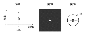
- 6A to 6C are diagrams showing an operation example in the CBC mode of the spatial optical communication apparatus according to Embodiment 1 of the present invention
- FIG. 6A is a diagram showing an example of an optical spectrum
- FIG. FIG. 6C is a diagram illustrating an example of a pattern
- FIG. 6C is a diagram illustrating an example of a positional relationship between an angle sensor and received light.
- It is a figure which shows the structural example of the space optical communication apparatus which concerns on Embodiment 2 of this invention.
- 8A and 8B are diagrams showing examples of simulation results of the output light intensity in the spatial optical communication apparatus according to Embodiment 2 of the present invention
- FIG. 8A is a diagram showing a case where there are two signal lights.
- FIG. 8B is a diagram showing a case where there are three signal lights. It is a figure which shows the operation example in the CBC mode of the space optical communication apparatus which concerns on Embodiment 2 of this invention, and is a figure which shows an example of a distant pattern.
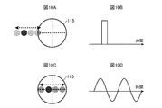
- 10A to 10D are diagrams showing an operation example in the ICBC mode of the spatial light communication apparatus according to Embodiment 2 of the present invention, and FIG. 10A is a diagram showing an example of the positional relationship between the angle sensor and the received light.
- 10B is a diagram illustrating an output example of the center of gravity calculation (before control), and FIG.
- FIG. 10C is a diagram illustrating an example of the positional relationship between the angle sensor and the received light (after control).
- 10D is a diagram (after control) showing an output example of the gravity center calculation.
- FIG. 11A is a diagram illustrating an arrangement example of a plurality of elements included in the optical phased array antenna according to Embodiment 3 of the present invention
- FIG. 11B is an image diagram illustrating an example of a temporal change in a peak position of a distant pattern.
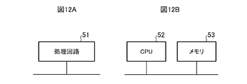
- 12A and 12B are diagrams showing a hardware configuration example of the signal processing unit in the first to third embodiments of the present invention.
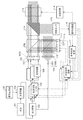
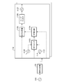
- FIG. 1 is a diagram showing a configuration example of a spatial light communication apparatus according to Embodiment 1 of the present invention.
- the spatial optical communication device is a phased array type spatial optical communication device that performs communication by outputting laser light to a space.
- the spatial optical communication apparatus includes a light source 101, a signal generation unit 102, an optical modulator 103, an optical distributor 104, n optical frequency shifters 105, n optical amplifiers 106, an optical phased array.
- n is an integer of 2 or more, and is the same number as the number of elements that the optical phased array antennas 107 and 111 have.
- the light source 101 emits laser light. Laser light emitted from the light source 101 is output to the optical modulator 103.
- the signal generator 102 generates a communication signal.
- the communication signal generated by the signal generation unit 102 is output to the optical modulator 103.
- the optical modulator 103 generates modulated light by superimposing the communication signal generated by the signal generator 102 on the laser light emitted from the light source 101.
- the optical modulator 103 for example, a Mach-Zehnder optical modulator is used.
- the modulated light generated by the optical modulator 103 is output to the optical distributor 104.
- the optical distributor 104 branches the modulated light generated by the optical modulator 103 into one local light and n signal lights.
- the optical distributor 104 for example, a polarization maintaining optical coupler is used.
- the local light obtained by the optical distributor 104 is output to the collimator 109, and the n signal lights obtained by the optical distributor 104 are distributed one by one to the n optical frequency shifters 105.
- the optical frequency shifter 105 adjusts the phase of the signal light distributed by the optical distributor 104 according to control by the phase control circuit 112.
- the signal light after the phase adjustment by the optical frequency shifter 105 is output to the optical amplifier 106 connected to the own device (optical frequency shifter 105).
- the n optical frequency shifters 105 constitute a “phase adjusting unit that adjusts the phase of each signal light obtained by the optical distributor 104”.
- the optical amplifier 106 amplifies the power of the signal light output from the optical frequency shifter 105 connected to the optical amplifier 106 (the optical amplifier 106).
- the optical amplifier 106 for example, an optical fiber amplifier or a semiconductor optical amplifier is used.
- the signal light amplified by the optical amplifier 106 is output to the optical phased array antenna 107.
- the n optical amplifiers 106 constitute “an optical amplification unit that amplifies each signal light after phase adjustment by the phase adjustment unit”.
- the optical phased array antenna 107 outputs the signal light output from each optical amplifier 106 to the space as collimated light.
- the optical phased array antenna 107 includes n collimators (elements) each including an optical fiber 1071 and a collimator lens 1072, and the n collimators are arranged in an array.
- One end of the optical fiber 1071 faces the output end of one optical amplifier 106, and the incident surface of the collimator lens 1072 faces the other end of the optical fiber 1071.
- the beam splitter 108 divides each of the n signal lights output from the optical phased array antenna 107 into two parts by transmitting a part of the incident light and reflecting the rest.
- the n signal lights that have passed through the beam splitter 108 are used for communication in the spatial light communication device. Further, the n signal lights reflected by the beam splitter 108 are used for phase error detection in the spatial light communication device.
- the collimator 109 outputs the local light output from the light distributor 104 to the space as collimated light.
- the collimator 109 includes an optical fiber 1091 having one end facing one of a plurality of output ends of the light distributor 104, and a collimator lens 1092 having an incident surface facing the other end of the optical fiber 1091.
- the beam splitter 110 transmits the n signal lights reflected by the beam splitter 108 and reflects the local light transmitted by the collimator 109, thereby combining the local light with the n signal lights. .
- the n signal lights combined with the local lights by the beam splitter 110 are output to the optical phased array antenna 111.
- the optical phased array antenna 111 receives n signal lights combined with local light emitted by the beam splitter 110.
- the optical phased array antenna 111 includes n collimators (elements) each including a collimator lens 1111 and a photodiode 1112, and the n collimators are arranged in an array.
- the collimator lens 1111 condenses one signal light combined with the local light by the beam splitter 110.
- the photodiode 1112 is an optical receiver that receives the signal light collected by the collimator lens 1111 and converts it into an electrical signal.
- a reception signal (electric signal) as a reception result by the optical phased array antenna 111 is output to each phase control circuit 112.
- the phase control circuit 112 is controlled by the signal processing unit 116 and the signal switching circuit 117, and based on the received signal output from the optical phased array antenna 111, the optical frequency shifter 105 connected to the own device (phase control circuit 112). Controls the amount of phase shift. At this time, the phase control circuit 112 detects the phase error between the reference signal and the received signal output from the optical phased array antenna 111, and outputs the phase error compensation signal for controlling the phase shift amount so as to eliminate this phase error. Output to the optical frequency shifter 105. Details of the phase control circuit 112 will be described later.
- the beam splitter 108, the collimator 109, the beam splitter 110, the optical phased array antenna 111, and the n phase control circuits 112 are “output by the optical phased array antenna 107 and controlled by the optical distributor 104 under the control of the phase adjustment unit. It constitutes a “phase control unit” that synchronizes each signal light combined with the obtained local light with a reference signal.
- the acquisition and tracking mechanism 113 adjusts the output angle (propagation angle) of n signal lights output from the optical phased array antenna 107 and transmitted through the wavelength separation splitter 114 according to control by the control circuit 118.
- an adaptive mirror is used as the capture and tracking mechanism 113.
- the wavelength separation splitter 114 is an optical path separation splitter that transmits the signal light that has passed through the beam splitter 108 and reflects received light that has arrived from the outside.
- the angle sensor 115 detects the arrival angle of the received light reflected by the wavelength separation splitter 114.
- a four-quadrant angle sensor is used as the angle sensor 115.
- a reception angle signal that is a detection result by the angle sensor 115 is output to the signal processing unit 116.
- the wavelength separation splitter 114 and the angle sensor 115 constitute an “angle detection unit that detects an arrival angle of received light that has arrived from the outside”.
- the signal processing unit 116 controls the phase control circuit 112, the signal switching circuit 117, and the control circuit 118 based on the detection result by the angle sensor 115. Details of the signal processing unit 116 will be described later.
- the signal switching circuit 117 switches the reference signal used in the phase control circuit 112 to the first reference signal or the second reference signal according to control by the signal processing unit 116.
- the first reference signal is a reference signal for capturing received light (initial capturing), and has a different frequency for each signal light. In the first embodiment, each first reference signal is set to a random frequency.
- the second reference signal is a communication reference signal and has the same frequency for each signal light.
- the control circuit 118 controls the capture and tracking mechanism 113 according to the control by the signal processing unit 116.
- the signal processing unit 116, the signal switching circuit 117, and the control circuit 118 indicate that “the reference signal used in the phase control unit is a plurality of first reference signals having different frequencies for each signal light, and is based on the detection result by the angle detection unit.
- the received light is supplemented by control of the acquisition and tracking mechanism 113, and after the acquisition is completed, the reference signal is set as a second reference signal having the same frequency as each signal light, and phase adjustment based on the detection result by the angle detection unit A control unit that performs tracking of the received light ”.
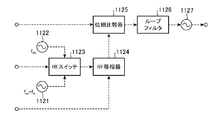
- the phase control circuit 112 includes a signal source 1121, a signal source 1122, an RF (Radio Frequency) switch 1123, an RF phase shifter 1124, a phase comparator 1125, a loop filter 1126, and a VCO (Voltage Controlled Oscillator). 1127.
- RF Radio Frequency
- the signal source 1121 generates a first reference signal.
- the first reference signal generated by the signal source 1121 is output to the RF switch 1123.
- the signal source 1122 generates a second reference signal.
- the second reference signal generated by the signal source 1122 is output to the RF switch 1123.
- the RF switch 1123 controls the RF phase shifter 1124 with one of the first reference signal output from the signal source 1121 and the second reference signal output from the signal source 1122 as a reference signal according to control by the signal switching circuit 117. Output.
- the RF phase shifter 1124 adjusts the phase of the reference signal output by the RF switch 1123 according to the control by the signal processing unit 116.
- the reference signal after the phase adjustment by the RF phase shifter 1124 is output to the phase comparator 1125.
- the phase comparator 1125 detects a phase error between the reference signal output from the RF phase shifter 1124 and the received signal output from the optical phased array antenna 111.
- a phase comparison signal that is a comparison result by the phase comparator 1125 is output to the loop filter 1126.
- the loop filter 1126 smoothes the phase comparison signal output from the phase comparator 1125.
- the phase comparison signal smoothed by the loop filter 1126 is output to the VCO 1127.
- the VCO 1127 Based on the phase comparison signal output from the loop filter 1126, the VCO 1127 generates a high-frequency signal for making the reception signal output from the optical phased array antenna 111 equal to the frequency of the reference signal output from the RF phase shifter 1124. Generate.
- the phase error compensation signal which is a high frequency signal generated by the VCO 1127, is output to the optical frequency shifter 105.
- the signal processing unit 116 includes a synchronization unit 1161, a first switching unit 1162, a first determination unit 1163, a first control unit 1164, a second switching unit 1165, a second determination unit 1166, and a second control. Part 1167.
- the synchronization unit 1161 controls the signal switching circuit 117 to synchronize each signal light with the frequency of the second reference signal.
- the first switching unit 1162 synchronizes each signal light with the frequency of the first reference signal by controlling the signal switching circuit 117 after the processing by the synchronization unit 1161 is completed.
- the first determination unit 1163 determines whether the detection result (the incoming angle of the received light) by the angle sensor 115 is within the first threshold after the processing by the first switching unit 1162 is completed.
- the first threshold is a value within a range in which the angle sensor 115 can detect the arrival angle of the received light.
- the first control unit 1164 controls the control circuit 118 to determine the arrival angle of the received light. Move towards the center of the.
- the second switching unit 1165 controls the signal switching circuit 117 to set each signal light to the second reference signal. Synchronize with the frequency.
- the second determination unit 1166 determines whether the detection result (the incoming angle of the received light) by the angle sensor 115 is within the second threshold after the processing by the second switching unit 1165 is completed.
- the second threshold value is a value within a range narrower than the first threshold value.
- the second control unit 1167 controls the RF phase shifter 1124 included in the phase control circuit 112 when the second determination unit 1166 determines that the arrival angle of the received light is not within the second threshold value.
- the light arrival angle is moved toward the center of the angle sensor 115.
- the light source 101 emits laser light
- the signal generation unit 102 generates a communication signal.
- the center frequency of the laser light emitted from the light source 101 is f 0 .
- the optical modulator 103 generates modulated light by superimposing the communication signal generated by the signal generator 102 on the laser light emitted from the light source 101.
- the optical distributor 104 branches the modulated light generated by the optical modulator 103 into one local light and n signal lights.
- the phase adjustment unit (n optical frequency shifters 105) adjusts the phase of the n signal lights obtained by the optical distributor 104.
- the optical amplification unit (n optical amplifiers 106) amplifies the n signal lights after the phase adjustment by the phase adjustment unit.
- the optical phased array antenna 107 outputs n signal lights amplified by the optical amplification unit to the space.
- the phase control unit (beam splitter 108, collimator 109, beam splitter 110, optical phased array antenna 111, and n phase control circuits 112) is output from the optical phased array antenna 107 and obtained by the optical distributor 104.
- the n signal lights combined with the local light are synchronized with the reference signal.
- the acquisition and tracking mechanism 113 adjusts the output angles of the n signal lights output from the optical phased array antenna 107.
- the angle detection unit (the wavelength separation splitter 114 and the angle sensor 115) detects the arrival angle of the received light coming from the outside. The detection result by the angle detection unit is notified to the signal processing unit 116, and the signal processing unit 116 captures and tracks the received light.
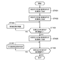
- the synchronization unit 1161 controls the signal switching circuit 117 to synchronize the n signal lights with the frequency of the second reference signal (step) ST401). That is, since the phase of n signal lights changes randomly depending on the optical path, the synchronization unit 1161 compensates for this phase fluctuation.
- the signal switching circuit 117 causes the reference signal used in each phase control circuit 112 to be the second reference signal in accordance with control by the synchronization unit 1161.
- the second reference signal is the same frequency for n of the signal light, the center frequency and f m.
- the spatial light communication apparatus performs the overall operation described above. As a result, the spatial light communication apparatus compensates for the phase error between the signal lights and makes the frequency and phase of the n signal lights the same.
- the first switching unit 1162 controls the signal switching circuit 117 to synchronize each signal light with the frequency of the first reference signal (step ST402).
- the operation mode of the spatial light communication device is set to the initial acquisition mode (ICBC mode).
- the signal switching circuit 117 causes the reference signal used in each phase control circuit 112 to be the first reference signal in accordance with the control by the first switching unit 1162.
- the first reference signal has a different frequency for each signal light, and the center frequency thereof is (f m + f n ).
- the optical spectrum of the output light from the optical phased array antenna 107 is shown in FIG. 5A.
- each phase control circuit 112 of the first embodiment the difference between adjacent frequencies of each first reference signal is set randomly so as not to be constant.
- the received light input to the angle sensor 115 of the spatial optical communication apparatus that is the communication partner becomes incoherent combination (ICBC) of n signal lights, and has a beam spread like a distant pattern shown in FIG. 5B. Light.
- ICBC incoherent combination
- the spatial light communication apparatus performs the overall operation described above, and starts supplementing received light (initial capture).
- first determination section 1163 determines whether the detection result (angle of arrival of received light) by angle sensor 115 is within the first threshold (step ST403).
- the first determination unit 1163 roughly determines the stability of signal light transmission and reception.
- the first control unit 1164 controls the control circuit 118 to control the received light.
- the arrival angle is moved toward the center of the angle sensor 115 (step ST404).
- FIG. 5C shows an example of the positional relationship between the angle sensor 115 and the received light. Thereafter, the sequence returns to step ST403.
- the second switching unit 1165 controls the signal switching circuit 117 to The signal light is synchronized with the frequency of the second reference signal (step ST405).
- the operation mode of the spatial light communication device is the tracking mode (CBC mode).
- the signal switching circuit 117 causes the reference signal used in each phase control circuit 112 to be the second reference signal according to the control by the second switching unit 1165.
- the optical spectrum of the output light from the optical phased array antenna 107 is shown in FIG. 6A.
- the received light input to the angle sensor 115 of the spatial light communication apparatus that is the communication partner is light having a sharp beam size with respect to the far pattern shown in FIG. 5B, like the far pattern shown in FIG. 6B. Therefore, the angle sensor 115 can detect the angle with high accuracy as compared with the case of capturing the received light.
- second determination section 1166 determines whether or not the detection result (angle of arrival of received light) by angle sensor 115 is within the second threshold (step ST406).
- the second determination unit 1166 determines the stability of signal light transmission and reception with high accuracy.
- the second control unit 1167 controls the phase control circuit 112 to receive the received light. Is moved toward the center of the angle sensor 115 (step ST407).
- FIG. 6C shows an example of the positional relationship between the angle sensor 115 and the received light. Thereafter, the sequence returns to step ST406.
- the signal processing unit 116 ends the sequence assuming that the tracking of the received light is completed. Thereafter, the spatial optical communication device starts optical communication with the spatial optical communication device that is the communication partner.
- the spatial optical communication device includes the optical distributor 104 that branches the modulated light into the local light and the plurality of signal lights, and each signal light obtained by the optical distributor 104.
- a phase adjustment unit that adjusts the phase
- an optical amplification unit that amplifies each signal light after phase adjustment by the phase adjustment unit
- an optical phased array antenna 107 that outputs each signal light amplified by the optical amplification unit to space
- a phase control unit that synchronizes each signal light, which is output from the optical phased array antenna 107 and obtained by the optical distributor 104 and combined with the local light, by a control of the phase adjustment unit with a reference signal, and an optical phased array antenna 107
- a capture and tracking mechanism 113 that adjusts the output angle of each signal light output from the signal 107
- an angle detection unit that detects the arrival angle of received light that has arrived from the outside, and a reference signal used in the phase control unit.
- the received light is supplemented by control of the acquisition and tracking mechanism 113 based on the detection result by the angle detection unit, and after the acquisition is completed, the reference signal is used as each signal light.
- a control unit for tracking the received light by controlling the phase adjustment unit based on the detection result by the angle detection unit.
- FIG. 7 is a diagram showing a configuration example of a spatial optical communication apparatus according to Embodiment 2 of the present invention.
- the spatial optical communication apparatus according to the second embodiment shown in FIG. 7 has a signal source 119 and a signal distributor 120 added to the spatial optical communication apparatus according to the first embodiment shown in FIG.
- FIG. 7 illustrates only the signal source 119, the signal distributor 120, and each phase control circuit 112 in the spatial optical communication apparatus according to the second embodiment.
- Other configurations of the spatial optical communication apparatus according to the second embodiment are the same as those of the spatial optical communication apparatus according to the first embodiment shown in FIG. 1, and only different parts will be described.
- the signal source 119 generates a third reference signal.
- the third reference signal is a reference signal for synchronizing each first reference signal.
- the third reference signal generated by the signal source 119 is output to the signal distributor 120.
- the signal distributor 120 branches the third reference signal generated by the signal source 119 into n pieces.
- the n third reference signals obtained by the signal distributor 120 are distributed one by one to the signal sources 1121 included in the n phase control circuits 112.
- the signal source 1121 generates a first reference signal synchronized with the third reference signal obtained by the signal distributor 120.
- the difference between adjacent frequencies is set to be constant for each first reference signal.
- the first determination unit 1163 performs a centroid operation on the detection result (arrival angle of received light) by the angle sensor 115, and the average value of the centroid operation is the first value. It is determined whether it is within one threshold.
- the first control unit 1164 controls the control circuit 118 to obtain the average value of the center of gravity calculation. It is moved toward the center of the angle sensor 115.
- the phase difference of each signal light periodically changes according to the difference in frequency.
- the phase difference of each signal light vibrates in the range of ⁇ ⁇ at 10 MHz.
- FIG. 8B shows a case where the spatial optical communication apparatus uses three signal lights and the frequency difference is 10 MHz.
- phased array type spatial optical communication apparatus that captures received light in a beaconless manner by performing beam scanning by electronically controlling the phase of each signal light.
- the scan rate is limited by the loop bandwidth of the PLL (Phase Locked Loop).
- the spatial light communication device when capturing received light, the frequency difference of each signal light is made constant so that the phase of each signal light is not electrically controlled. , Sweep.
- the spatial optical communication apparatus is not limited to the loop bandwidth of the PLL, and can perform high-speed beam scanning in the MHz band or higher.
- the difference between adjacent frequencies of the first reference signals is equal to or less than the reception band of the angle sensor 115.
- f d is several tens of MHz to several GHz when the angle sensor 115 is a four-quadrant photodiode.
- the scan rate is limited to the loop bandwidth of the PLL of less than 100 kHz.
- FIG. 9 shows a temporal change of the far pattern when the spatial light communication apparatus uses four signal lights.
- each signal light is instantaneously coherently combined with the supplement of the received light in the first embodiment, so that the peak intensity is the number of signal lights. Only increase.
- a received signal having a certain width as shown in FIG. 10B is obtained.
- the signal processing unit 116 controls the acquisition and tracking mechanism 113 so that the average value of the center of gravity calculation of the received signal approaches the center of the angle sensor 115 so that the average value is within the first threshold (see FIG. 10A to FIG. 10D).
- the subsequent processing is the same as in the first embodiment.
- the present invention is not limited to this, and a plurality of elements included in the optical phased array antenna 107 may be two-dimensionally arranged.
- the first reference signals used in the phase control unit are synchronized with each other, and the difference between adjacent frequencies is constant.
- the spatial optical communication apparatus according to the second embodiment is 10 times faster than the conventional beam scan rate in which the phase of each signal light is electronically controlled in analog in addition to the effects of the first embodiment. Beam scanning can be realized.
- Embodiment 3 In the spatial optical communication apparatus according to the second embodiment, the case where a plurality of elements included in the optical phased array antenna 107 is one-dimensionally arranged or two-dimensionally arranged is shown.
- a plurality of elements included in the optical phased array antenna 107 are arranged in a triangle, and each first reference signal has a frequency spirally with respect to the plurality of elements. The case where it becomes large is shown.
- the configuration example of the spatial optical communication apparatus according to Embodiment 3 is the same as the configuration example of the spatial optical communication apparatus according to Embodiment 2 shown in FIG.
- FIG. 11A shows an arrangement example of a plurality of elements included in the optical phased array antenna 107
- FIG. 11B shows an example of a time change of a peak position in a distant pattern by arrows.
- Reference signs f 0 to f 18 in FIG. 11A indicate the frequency of the signal light for each element.
- the plurality of elements included in the optical phased array antenna 107 are arranged in a triangular arrangement as shown in FIG. 11A, and the frequency of each first reference signal corresponding to each element is expressed by the following formula ( 4).
- f i is the frequency of the i-th first reference signal
- f i-1 is the frequency of the i-1th first reference signal.
- f i f i ⁇ 1 + ⁇ f (4)
- the distant pattern is scanned in a spiral shape (spiral shape) at a rate of 2 ⁇ f.
- the spatial light communication apparatus according to Embodiment 3 can capture received light without omission of scanning by performing a spiral scan.
- the functions of the synchronization unit 1161, the first switching unit 1162, the first determination unit 1163, the first control unit 1164, the second switching unit 1165, the second determination unit 1166, and the second control unit 1167 in the signal processing unit 116 are processing. This is realized by the circuit 51.
- the processing circuit 51 may be dedicated hardware as shown in FIG. 12A, or as shown in FIG.
- a CPU Central Processing Unit
- a central processing unit It may be a processing device, an arithmetic device, a microprocessor, a microcomputer, a processor, or a DSP (Digital Signal Processor)) 52.
- the processing circuit 51 may be, for example, a single circuit, a composite circuit, a programmed processor, a parallel programmed processor, an ASIC (Application Specific Integrated Circuit), or an FPGA (Field Programmable Gate). Array) or a combination thereof.
- the processing circuit 51 implements the functions of the synchronization unit 1161, the first switching unit 1162, the first determination unit 1163, the first control unit 1164, the second switching unit 1165, the second determination unit 1166, and the second control unit 1167. Alternatively, the functions of the respective units may be integrated and realized by the processing circuit 51.
- the processing circuit 51 When the processing circuit 51 is the CPU 52, the functions of the synchronization unit 1161, the first switching unit 1162, the first determination unit 1163, the first control unit 1164, the second switching unit 1165, the second determination unit 1166, and the second control unit 1167 are as follows. , Software, firmware, or a combination of software and firmware. Software and firmware are described as programs and stored in the memory 53.
- the processing circuit 51 implements the functions of each unit by reading and executing the program stored in the memory 53. That is, the signal processing unit 116 includes a memory 53 for storing a program that, when executed by the processing circuit 51, for example, causes each step shown in FIG. 4 to be executed as a result.
- these programs are the procedures and methods of the synchronization unit 1161, the first switching unit 1162, the first determination unit 1163, the first control unit 1164, the second switching unit 1165, the second determination unit 1166, and the second control unit 1167. It can be said that it is what makes a computer execute.
- the memory 53 for example, a nonvolatile or volatile semiconductor memory such as a RAM (Random Access Memory), a ROM (Read Only Memory), a flash memory, an EPROM (Erasable Programmable ROM), an EEPROM (Electrically EPROM), or the like.
- a magnetic disk, a flexible disk, an optical disk, a compact disk, a mini disk, a DVD (Digital Versatile Disc), or the like is applicable.
- a part of each function of the synchronization unit 1161, the first switching unit 1162, the first determination unit 1163, the first control unit 1164, the second switching unit 1165, the second determination unit 1166, and the second control unit 1167 is dedicated. It may be realized by hardware of the above, and a part may be realized by software or firmware.
- the function of the synchronization unit 1161 is realized by the processing circuit 51 as dedicated hardware, and the first switching unit 1162, the first determination unit 1163, the first control unit 1164, the second switching unit 1165, and the second determination.
- the functions of the unit 1166 and the second control unit 1167 can be realized by the processing circuit 51 reading and executing the program stored in the memory 53.
- the processing circuit 51 can realize the above-described functions by hardware, software, firmware, or a combination thereof.
- the spatial optical communication apparatus can output communication light and beacon light using a single optical antenna, and is suitable for use in a spatial optical communication apparatus that performs communication by outputting laser light to space. Yes.
Landscapes
- Physics & Mathematics (AREA)
- Electromagnetism (AREA)
- Engineering & Computer Science (AREA)
- Computer Networks & Wireless Communication (AREA)
- Signal Processing (AREA)
- Astronomy & Astrophysics (AREA)
- General Physics & Mathematics (AREA)
- Optical Communication System (AREA)
- Variable-Direction Aerials And Aerial Arrays (AREA)
- Radio Transmission System (AREA)
Abstract
Dispositif de communication optique spatial comprenant : un distributeur optique (104) qui divise une lumière modulée en une lumière locale et une pluralité de signaux lumineux; une unité de réglage de phase qui ajuste la phase de chaque signal lumineux obtenu par le distributeur optique (104); une unité d'amplification optique qui amplifie chaque signal lumineux après l'ajustement de phase par l'unité de réglage de phase; une antenne réseau à commande de phase optique (107) qui fournit dans l'espace chaque signal lumineux amplifié par l'unité d'amplification optique; une unité de commande de phase qui synchronise chaque signal lumineux, qui a été émis par l'antenne réseau à commande de phase optique (107) et ensuite combiné avec la lumière locale obtenue par le distributeur optique (104), avec un signal de référence en utilisant la commande de l'unité de réglage de phase; un mécanisme de poursuite de capture (113) qui règle l'angle de sortie de chaque signal lumineux émis par l'antenne réseau à commande de phase optique (107); une unité de détection d'angle qui détecte l'angle d'arrivée d'une lumière reçue qui est arrivée de l'extérieur; et une unité de commande qui fournit, en tant que signal de référence à utiliser dans l'unité de commande de phase, une pluralité de premiers signaux de référence ayant des fréquences différentes pour les signaux lumineux respectifs, capture la lumière reçue en utilisant la commande du mécanisme de poursuite de capture (113) sur la base d'un résultat de la détection par l'unité de détection angulaire, fournit, comme signal de référence, des deuxièmes signaux de référence ayant les mêmes fréquences pour les signaux lumineux respectifs après la capture, et suit la lumière reçue en utilisant la commande de l'unité de réglage de phase basée sur le résultat de la détection par l'unité de détection angulaire.
Priority Applications (4)
| Application Number | Priority Date | Filing Date | Title |
|---|---|---|---|
| PCT/JP2018/017163 WO2019207756A1 (fr) | 2018-04-27 | 2018-04-27 | Dispositif de communication optique spatial |
| EP18915820.7A EP3761528B1 (fr) | 2018-04-27 | 2018-04-27 | Dispositif de communication optique spatial |
| JP2020515423A JP6746039B2 (ja) | 2018-04-27 | 2018-04-27 | 空間光通信装置 |
| US17/033,118 US11223420B2 (en) | 2018-04-27 | 2020-09-25 | Free-space optical communication apparatus |
Applications Claiming Priority (1)
| Application Number | Priority Date | Filing Date | Title |
|---|---|---|---|
| PCT/JP2018/017163 WO2019207756A1 (fr) | 2018-04-27 | 2018-04-27 | Dispositif de communication optique spatial |
Related Child Applications (1)
| Application Number | Title | Priority Date | Filing Date |
|---|---|---|---|
| US17/033,118 Continuation US11223420B2 (en) | 2018-04-27 | 2020-09-25 | Free-space optical communication apparatus |
Publications (1)
| Publication Number | Publication Date |
|---|---|
| WO2019207756A1 true WO2019207756A1 (fr) | 2019-10-31 |
Family
ID=68293948
Family Applications (1)
| Application Number | Title | Priority Date | Filing Date |
|---|---|---|---|
| PCT/JP2018/017163 Ceased WO2019207756A1 (fr) | 2018-04-27 | 2018-04-27 | Dispositif de communication optique spatial |
Country Status (4)
| Country | Link |
|---|---|
| US (1) | US11223420B2 (fr) |
| EP (1) | EP3761528B1 (fr) |
| JP (1) | JP6746039B2 (fr) |
| WO (1) | WO2019207756A1 (fr) |
Cited By (9)
| Publication number | Priority date | Publication date | Assignee | Title |
|---|---|---|---|---|
| CN111277334A (zh) * | 2020-01-20 | 2020-06-12 | 中国科学院上海光学精密机械研究所 | 一种大口径阵列式多维光学相控阵通信系统 |
| WO2021255771A1 (fr) * | 2020-06-15 | 2021-12-23 | 日本電信電話株式会社 | Dispositif de communication optique sans fil et procédé de communication optique sans fil |
| US20230012584A1 (en) * | 2020-06-05 | 2023-01-19 | Mitsubishi Electric Corporation | Receiver, optical space communication system, and optical space communication reception method |
| JP2024535313A (ja) * | 2021-09-21 | 2024-09-30 | エックス デベロップメント エルエルシー | ワイヤレス光通信端末のための光学追跡モジュールチップ |
| US12153324B2 (en) | 2021-09-21 | 2024-11-26 | X Development Llc | Optical phased array architecture for wavefront sensing |
| WO2025004159A1 (fr) * | 2023-06-27 | 2025-01-02 | 三菱電機株式会社 | Émetteur-récepteur de communication optique spatiale |
| WO2025052495A1 (fr) * | 2023-09-04 | 2025-03-13 | 三菱電機株式会社 | Dispositif de transmission de faisceau optique |
| JPWO2025141625A1 (fr) * | 2023-12-25 | 2025-07-03 | ||
| US12592772B2 (en) | 2021-09-21 | 2026-03-31 | Taara Connect, Inc. | Integrated on-chip wireless optical communication terminal |
Families Citing this family (21)
| Publication number | Priority date | Publication date | Assignee | Title |
|---|---|---|---|---|
| KR102650098B1 (ko) * | 2019-11-14 | 2024-03-22 | 아날로그 포토닉스, 엘엘씨 | 어레이-기반 자유-공간 광학 통신 링크들 |
| JP7440802B2 (ja) * | 2020-06-24 | 2024-02-29 | 日本電信電話株式会社 | 通信装置及び光通信システム |
| US11934048B2 (en) | 2021-01-29 | 2024-03-19 | Raytheon Company | Photonic integrated circuit-based coherently phased array laser transmitter |
| US11644621B2 (en) | 2021-02-11 | 2023-05-09 | Raytheon Company | Digital input circuit design for photonic integrated circuit |
| US11476576B2 (en) * | 2021-02-11 | 2022-10-18 | Raytheon Company | Photonic integrated circuit-based communication transmit/receive system |
| US11988903B2 (en) | 2021-02-11 | 2024-05-21 | Raytheon Company | Photonic integrated circuit-based optical phased array calibration technique |
| US11532881B2 (en) | 2021-02-11 | 2022-12-20 | Raytheon Company | Photonic integrated circuit-based optical phased array phasing technique |
| CN113162696B (zh) | 2021-02-23 | 2022-06-10 | 鹏城实验室 | 片上自适应光接收机系统、光芯片及通信设备 |
| JP2024546421A (ja) * | 2021-11-10 | 2024-12-24 | レイセオン ビービーエヌ テクノロジーズ コープ | 光フェーズドアレイを備えたフォトニックイジング計算エンジン |
| US11962350B2 (en) | 2022-03-09 | 2024-04-16 | Raytheon Company | Photonic integrated circuit with independent unit cells having multi-polarization sensitivity |
| CN114499665B (zh) * | 2022-03-10 | 2022-07-12 | 鹏城实验室 | 一种多对多激光通信组网装置和方法 |
| US11722236B1 (en) | 2022-04-05 | 2023-08-08 | Ii-Vi Delaware, Inc. | Polarization-maintaining wavelength selective switch for free-space optical communication |
| US12088343B2 (en) | 2022-04-19 | 2024-09-10 | Raytheon Company | Photonic integrated circuit-based polarization-independent optical devices |
| US12189180B2 (en) | 2022-06-14 | 2025-01-07 | Raytheon Company | Photonic integrated circuit multi-wavelength phase modulator networks |
| US11894873B2 (en) | 2022-06-29 | 2024-02-06 | Raytheon Company | Photonic integrated circuit with inverted H-tree unit cell design |
| US12261645B2 (en) | 2022-07-08 | 2025-03-25 | Raytheon Company | Multi-node, multi-stream photonic integrated circuit-based free-space optical communication device |
| US11888515B1 (en) | 2022-07-14 | 2024-01-30 | Raytheon Company | System and method for parallel real-time photonic integrated circuit (PIC) optical phased array calibration and ultraviolet laser micro-ring wavelength offset trimming |
| CN115567115B (zh) * | 2022-08-16 | 2025-06-27 | 北京遥测技术研究所 | 一种基于多孔径相干合成的光学相控阵激光通信系统 |
| US12308887B2 (en) | 2022-11-15 | 2025-05-20 | Raytheon Company | Integrated photonic integrated circuit (PIC) and readout integrated circuit (ROIC) for high-speed data output from focal plane array |
| CN119945553B (zh) * | 2024-12-25 | 2025-12-05 | 暨南大学 | 自由空间光多维复用与多维分集通信系统 |
| CN120110527B (zh) * | 2025-03-27 | 2025-11-28 | 鹏城实验室 | 星间激光通信跟踪一体化装置及方法 |
Citations (6)
| Publication number | Priority date | Publication date | Assignee | Title |
|---|---|---|---|---|
| JPH08162836A (ja) * | 1994-12-06 | 1996-06-21 | Nippon Telegr & Teleph Corp <Ntt> | フェーズドアレー用ビーム成形回路 |
| US20040208595A1 (en) * | 2002-02-19 | 2004-10-21 | Fai Mok | Free space communication system with common optics and fast, adaptive tracking |
| JP2005229253A (ja) | 2004-02-12 | 2005-08-25 | Olympus Corp | 空間光伝送装置 |
| JP2007511968A (ja) * | 2003-11-17 | 2007-05-10 | メディア ラリオ ソシエタ ア レスポンサビリタ リミタータ | 光空間通信 |
| JP2012060499A (ja) * | 2010-09-10 | 2012-03-22 | National Institute Of Information & Communication Technology | 光無線通信装置 |
| JP2016517655A (ja) * | 2013-03-15 | 2016-06-16 | レイセオン カンパニー | アジャイルビームベースの保護スイッチングを用いる自由空間光ネットワーク |
Family Cites Families (19)
| Publication number | Priority date | Publication date | Assignee | Title |
|---|---|---|---|---|
| JP3859335B2 (ja) * | 1996-12-17 | 2006-12-20 | Nec東芝スペースシステム株式会社 | 光通信装置および光通信システム |
| JP2000059307A (ja) * | 1998-08-10 | 2000-02-25 | Sony Corp | 光無線装置 |
| US6708003B1 (en) * | 1999-12-16 | 2004-03-16 | Northrop Grumman Corporation | Optical energy transmission system utilizing precise phase and amplitude control |
| JP2001292104A (ja) * | 2000-04-06 | 2001-10-19 | Canon Inc | 光空間伝送装置 |
| JP2001326608A (ja) * | 2000-05-15 | 2001-11-22 | Canon Inc | 光空間通信装置 |
| DE10118335A1 (de) | 2001-04-12 | 2002-10-17 | Bosch Gmbh Robert | Vorrichtung und eine Anlage zur optischen Übertragung von Daten zwischen Satelliten |
| US7406220B1 (en) * | 2006-03-09 | 2008-07-29 | Lockheed Martin Coherent Technologies, Inc. | Beam steering and combination |
| WO2009073158A1 (fr) * | 2007-11-30 | 2009-06-11 | Raytheon Company | Procédé et appareil pour maintenir un faisceau combiné cohérent pendant un guidage arbitraire |
| US9753351B2 (en) * | 2014-06-30 | 2017-09-05 | Quanergy Systems, Inc. | Planar beam forming and steering optical phased array chip and method of using same |
| US10598785B2 (en) * | 2016-02-11 | 2020-03-24 | California Institute Of Technology | Hybrid transmitter receiver optical imaging system |
| WO2017205442A2 (fr) * | 2016-05-24 | 2017-11-30 | The Charles Stark Draper Laboratory, Inc. | Émetteur à commande de phase et récepteur à miroir à conjugaison de phase pour système de communication optique |
| US10382140B2 (en) * | 2016-06-07 | 2019-08-13 | California Institute Of Technology | Optical sparse phased array receiver |
| US10303037B2 (en) * | 2016-06-14 | 2019-05-28 | The Charles Stark Draper Laboratory, Inc. | Wide angle steering with phase array with wide-element spacing and lens array |
| US20180120422A1 (en) * | 2016-11-03 | 2018-05-03 | Quanergy Systems, Inc. | Low cost and compact optical phased array with electro-optic beam steering |
| US10203452B2 (en) * | 2016-12-30 | 2019-02-12 | Intel Corporation | Wide-angle, aliasing-free beam steering using aperiodic emitter arrays |
| WO2018148758A1 (fr) * | 2017-02-13 | 2018-08-16 | California Institute Of Technology | Adressage matriciel passif de réseaux à commande de phase optique |
| US11336373B2 (en) * | 2017-03-09 | 2022-05-17 | California Institute Of Technology | Co-prime optical transceiver array |
| US10705407B2 (en) * | 2017-05-08 | 2020-07-07 | Analog Photonics LLC | Speckle reduction in photonic phased arrays |
| US10598968B2 (en) * | 2018-01-19 | 2020-03-24 | Robert Bosch Gmbh | Temperature feedback for electro-optic phase-shifters |
-
2018
- 2018-04-27 WO PCT/JP2018/017163 patent/WO2019207756A1/fr not_active Ceased
- 2018-04-27 EP EP18915820.7A patent/EP3761528B1/fr active Active
- 2018-04-27 JP JP2020515423A patent/JP6746039B2/ja active Active
-
2020
- 2020-09-25 US US17/033,118 patent/US11223420B2/en active Active
Patent Citations (6)
| Publication number | Priority date | Publication date | Assignee | Title |
|---|---|---|---|---|
| JPH08162836A (ja) * | 1994-12-06 | 1996-06-21 | Nippon Telegr & Teleph Corp <Ntt> | フェーズドアレー用ビーム成形回路 |
| US20040208595A1 (en) * | 2002-02-19 | 2004-10-21 | Fai Mok | Free space communication system with common optics and fast, adaptive tracking |
| JP2007511968A (ja) * | 2003-11-17 | 2007-05-10 | メディア ラリオ ソシエタ ア レスポンサビリタ リミタータ | 光空間通信 |
| JP2005229253A (ja) | 2004-02-12 | 2005-08-25 | Olympus Corp | 空間光伝送装置 |
| JP2012060499A (ja) * | 2010-09-10 | 2012-03-22 | National Institute Of Information & Communication Technology | 光無線通信装置 |
| JP2016517655A (ja) * | 2013-03-15 | 2016-06-16 | レイセオン カンパニー | アジャイルビームベースの保護スイッチングを用いる自由空間光ネットワーク |
Non-Patent Citations (1)
| Title |
|---|
| See also references of EP3761528A4 |
Cited By (21)
| Publication number | Priority date | Publication date | Assignee | Title |
|---|---|---|---|---|
| CN111277334B (zh) * | 2020-01-20 | 2022-09-02 | 中国科学院上海光学精密机械研究所 | 一种大口径阵列式多维光学相控阵通信系统 |
| CN111277334A (zh) * | 2020-01-20 | 2020-06-12 | 中国科学院上海光学精密机械研究所 | 一种大口径阵列式多维光学相控阵通信系统 |
| US20230012584A1 (en) * | 2020-06-05 | 2023-01-19 | Mitsubishi Electric Corporation | Receiver, optical space communication system, and optical space communication reception method |
| US12088339B2 (en) * | 2020-06-05 | 2024-09-10 | Mitsubishi Electric Corporation | Receiver, optical space communication system, and optical space communication reception method |
| US12224797B2 (en) * | 2020-06-15 | 2025-02-11 | Nippon Telegraph And Telephone Corporation | Optical wireless communication device and optical wireless communication method |
| WO2021255771A1 (fr) * | 2020-06-15 | 2021-12-23 | 日本電信電話株式会社 | Dispositif de communication optique sans fil et procédé de communication optique sans fil |
| JPWO2021255771A1 (fr) * | 2020-06-15 | 2021-12-23 | ||
| US20230224036A1 (en) * | 2020-06-15 | 2023-07-13 | Nippon Telegraph And Telephone Corporation | Optical wireless communication device and optical wireless communication method |
| JP7560763B2 (ja) | 2020-06-15 | 2024-10-03 | 日本電信電話株式会社 | 光無線通信装置及び光無線通信方法 |
| JP7668959B2 (ja) | 2021-09-21 | 2025-04-25 | エックス デベロップメント エルエルシー | ワイヤレス光通信端末のための光学追跡モジュールチップ |
| US12153324B2 (en) | 2021-09-21 | 2024-11-26 | X Development Llc | Optical phased array architecture for wavefront sensing |
| JP2024535313A (ja) * | 2021-09-21 | 2024-09-30 | エックス デベロップメント エルエルシー | ワイヤレス光通信端末のための光学追跡モジュールチップ |
| US12592772B2 (en) | 2021-09-21 | 2026-03-31 | Taara Connect, Inc. | Integrated on-chip wireless optical communication terminal |
| WO2025004159A1 (fr) * | 2023-06-27 | 2025-01-02 | 三菱電機株式会社 | Émetteur-récepteur de communication optique spatiale |
| WO2025004466A1 (fr) * | 2023-06-27 | 2025-01-02 | 三菱電機株式会社 | Émetteur-récepteur de communication optique spatiale |
| JPWO2025004466A1 (fr) * | 2023-06-27 | 2025-01-02 | ||
| JP7696516B2 (ja) | 2023-06-27 | 2025-06-20 | 三菱電機株式会社 | 空間光通信送受信機 |
| WO2025052495A1 (fr) * | 2023-09-04 | 2025-03-13 | 三菱電機株式会社 | Dispositif de transmission de faisceau optique |
| JP7693150B1 (ja) * | 2023-09-04 | 2025-06-16 | 三菱電機株式会社 | 光ビーム送信装置 |
| JPWO2025141625A1 (fr) * | 2023-12-25 | 2025-07-03 | ||
| JP7802249B2 (ja) | 2023-12-25 | 2026-01-19 | 三菱電機株式会社 | 位相同期レーザ装置 |
Also Published As
| Publication number | Publication date |
|---|---|
| JP6746039B2 (ja) | 2020-08-26 |
| US11223420B2 (en) | 2022-01-11 |
| US20210013966A1 (en) | 2021-01-14 |
| JPWO2019207756A1 (ja) | 2020-08-20 |
| EP3761528B1 (fr) | 2022-08-31 |
| EP3761528A1 (fr) | 2021-01-06 |
| EP3761528A4 (fr) | 2021-03-17 |
Similar Documents
| Publication | Publication Date | Title |
|---|---|---|
| JP6746039B2 (ja) | 空間光通信装置 | |
| US11555923B2 (en) | LIDAR system with speckle mitigation | |
| KR102847507B1 (ko) | 타겟 환경의 동시 빔 스캐닝을 위한 멀티 채널 레이저 모듈 기반의 lidar 시스템 | |
| US11187807B2 (en) | Precisely controlled chirped diode laser and coherent lidar system | |
| US10224694B2 (en) | Method and apparatus for coherence enhancement of sweep velocity locked lasers via all-electronic upconversion | |
| US9115971B2 (en) | Measuring apparatus | |
| US20090092158A1 (en) | Multi-aperture Three-Dimensional Beamforming | |
| CN114706095A (zh) | 空间分析测量系统和方法 | |
| EP3167310A2 (fr) | Lidar à vivacité de fréquence | |
| JP7454711B2 (ja) | リュードベリ分子ベースのマイクロ波方向探知 | |
| US20220334226A1 (en) | High resolution frequency modulated continuous wave lidar with solid-state beam steering | |
| JP2016166816A (ja) | コヒーレントレーザレーダ装置および目標測定方法 | |
| US11867814B1 (en) | Techniques for driving a laser diode in a LIDAR system | |
| US11789131B1 (en) | Techniques for using an electro-optical phase locked loop in a LIDAR system | |
| JP5334619B2 (ja) | 光路長制御装置 | |
| WO2022003893A1 (fr) | Dispositif de communication optique en espace libre | |
| US20240255642A1 (en) | Digital electro-optical phase locked loop in a lidar system | |
| JP6394797B2 (ja) | 周波数同期装置及び周波数同期システム | |
| JP2005318430A (ja) | フェイズドアレイアンテナシステム及びフェイズドアレイアンテナのビーム制御方法。 | |
| JP2007170990A (ja) | 微小移動検出装置 | |
| US20240255626A1 (en) | Hybrid laser driver and methods for using electro-optical phase-locked loop and algorithmic frequency locking | |
| US20250093480A1 (en) | Multi-channel coherent lidar apparatus | |
| JP7693150B1 (ja) | 光ビーム送信装置 | |
| WO2025127050A1 (fr) | Dispositif de correction de signal et procédé de correction de signal | |
| US20240183954A1 (en) | Techniques for a laser driver circuit with analog mixer and offset |
Legal Events
| Date | Code | Title | Description |
|---|---|---|---|
| 121 | Ep: the epo has been informed by wipo that ep was designated in this application |
Ref document number: 18915820 Country of ref document: EP Kind code of ref document: A1 |
|
| ENP | Entry into the national phase |
Ref document number: 2020515423 Country of ref document: JP Kind code of ref document: A |
|
| ENP | Entry into the national phase |
Ref document number: 2018915820 Country of ref document: EP Effective date: 20200930 |
|
| NENP | Non-entry into the national phase |
Ref country code: DE |