WO2019208104A1 - Outil d'entraînement - Google Patents
Outil d'entraînement Download PDFInfo
- Publication number
- WO2019208104A1 WO2019208104A1 PCT/JP2019/014016 JP2019014016W WO2019208104A1 WO 2019208104 A1 WO2019208104 A1 WO 2019208104A1 JP 2019014016 W JP2019014016 W JP 2019014016W WO 2019208104 A1 WO2019208104 A1 WO 2019208104A1
- Authority
- WO
- WIPO (PCT)
- Prior art keywords
- wire
- striking
- unit
- engaging
- driving machine
- Prior art date
- Legal status (The legal status is an assumption and is not a legal conclusion. Google has not performed a legal analysis and makes no representation as to the accuracy of the status listed.)
- Ceased
Links
Images















Classifications
-
- B—PERFORMING OPERATIONS; TRANSPORTING
- B25—HAND TOOLS; PORTABLE POWER-DRIVEN TOOLS; MANIPULATORS
- B25C—HAND-HELD NAILING OR STAPLING TOOLS; MANUALLY OPERATED PORTABLE STAPLING TOOLS
- B25C1/00—Hand-held nailing tools; Nail feeding devices
- B25C1/04—Hand-held nailing tools; Nail feeding devices operated by fluid pressure, e.g. by air pressure
-
- B—PERFORMING OPERATIONS; TRANSPORTING
- B25—HAND TOOLS; PORTABLE POWER-DRIVEN TOOLS; MANIPULATORS
- B25C—HAND-HELD NAILING OR STAPLING TOOLS; MANUALLY OPERATED PORTABLE STAPLING TOOLS
- B25C1/00—Hand-held nailing tools; Nail feeding devices
- B25C1/04—Hand-held nailing tools; Nail feeding devices operated by fluid pressure, e.g. by air pressure
- B25C1/047—Mechanical details
-
- B—PERFORMING OPERATIONS; TRANSPORTING
- B25—HAND TOOLS; PORTABLE POWER-DRIVEN TOOLS; MANIPULATORS
- B25C—HAND-HELD NAILING OR STAPLING TOOLS; MANUALLY OPERATED PORTABLE STAPLING TOOLS
- B25C1/00—Hand-held nailing tools; Nail feeding devices
- B25C1/06—Hand-held nailing tools; Nail feeding devices operated by electric power
-
- B—PERFORMING OPERATIONS; TRANSPORTING
- B25—HAND TOOLS; PORTABLE POWER-DRIVEN TOOLS; MANIPULATORS
- B25C—HAND-HELD NAILING OR STAPLING TOOLS; MANUALLY OPERATED PORTABLE STAPLING TOOLS
- B25C1/00—Hand-held nailing tools; Nail feeding devices
- B25C1/04—Hand-held nailing tools; Nail feeding devices operated by fluid pressure, e.g. by air pressure
- B25C1/041—Hand-held nailing tools; Nail feeding devices operated by fluid pressure, e.g. by air pressure with fixed main cylinder
- B25C1/043—Trigger valve and trigger mechanism
-
- B—PERFORMING OPERATIONS; TRANSPORTING
- B25—HAND TOOLS; PORTABLE POWER-DRIVEN TOOLS; MANIPULATORS
- B25C—HAND-HELD NAILING OR STAPLING TOOLS; MANUALLY OPERATED PORTABLE STAPLING TOOLS
- B25C7/00—Accessories for nailing or stapling tools, e.g. supports
Definitions
- the present invention relates to a driving machine including a hitting unit that hits a stopper.
- Patent Document 1 An example of a driving machine that performs a striking unit that operates in a first direction with the pressure of a compressible gas and a driving unit that operates the striking unit in a second direction opposite to the first direction is disclosed in Patent Document 1.
- the driving machine described in Patent Document 1 includes a housing, a striking unit, an injection unit, a blocking mechanism, a bellows, and a driving unit.
- the injection part is fixed to the housing, and the striking part has a piston and a driver blade.
- the first end of the bellows is connected to the piston, and the second end of the bellows is fixed in the housing.
- a pressure accumulation chamber is formed in the bellows, and a compressible gas is sealed in the pressure accumulation chamber.
- the drive unit includes an electric motor, a pair of gears, a belt wound around the pair of gears, a rotation shaft, a rotation shaft around which the gear is wound, a winding body attached to the rotation shaft, and a wire.
- One end is wound around a pulley and the second end of the wire is connected to the piston.
- the blocking mechanism connects and blocks the path for transmitting the rotational force of the rotating shaft to the pulley.
- the pair of gears and the belt are disposed on the outer side in the radial direction of the bellows with respect to the region in which the bellows forming the pressure accumulating chamber is disposed.
- the bellows is arrange
- the inventor of the present application has recognized the problem that the compressible gas leaks in the pressure accumulating chamber and the driving machine may be enlarged depending on the arrangement positions of the striking unit and the driving unit.
- the objective of this invention is providing the driving device which can improve the sealing performance of a pressure accumulation chamber, and can suppress enlargement.
- the driving machine includes an injection unit to which a stopper is supplied, a pressure accumulating chamber that stores a compressible gas, and a striking unit that operates in a first direction in which the stopper is struck by the pressure of the compressible gas.
- a wire connected to the striking part, and a drive part that pulls the wire to actuate the striking part in a second direction opposite to the first direction to increase the pressure in the pressure accumulating chamber.
- a housing provided with at least one of the pressure accumulating chamber, the striking portion, and the driving portion, and forming at least a part of the pressure accumulating chamber, and a center line being the striking
- a cylinder disposed along the operating direction of the part, and a piston formed on the striking part and sliding with respect to the inner peripheral surface of the cylinder when the striking part operates in the center line direction, Provided, all of the drive unit and the wire are In the radial direction of the serial cylinder, wherein the piston is outside the region is located, and, in the actuating direction of the striking part, the piston is provided in a region outside that slides against the cylinder.
- the driving machine includes an injection unit to which a stopper is supplied, a pressure accumulating chamber for storing a compressible gas, and a striking unit that operates in the first direction to hit the stopper with the pressure of the compressible gas. And a shock absorbing member that collides with the striking part that operates in the first direction, a wire connected to the striking part, and pulling the wire to make the striking part in a direction opposite to the first direction.
- a driving machine having a drive unit that operates in a second direction to increase the pressure of the pressure accumulating chamber, and a housing in which at least one of the pressure accumulating chamber, the striking unit, and the driving unit is provided,
- the drive unit and the wire are all provided between the buffer member and the tip of the injection unit that is farthest from the buffer member in the operation direction of the hitting unit.
- Still another embodiment of the driving machine includes an injection unit to which a stopper is supplied, a pressure accumulating chamber for storing the compressible gas, and a hammer that operates in a first direction in which the stopper is hit with the pressure of the compressible gas.
- a drive that raises the pressure in the pressure accumulating chamber by operating the striking part in a second direction opposite to the first direction by pulling the wire, and a wire connected to the striking part
- a housing provided with at least one of the pressure accumulating chamber, the striking part, and the driving part, wherein the driving part is provided on the rotating member and the rotating member, And an engaging portion that can be engaged with and released from the wire, and the rotating member rotates in a state where the engaging portion is engaged with the wire and pulls the wire.
- the driving machine can improve the sealing performance of the pressure accumulating chamber and can suppress an increase in size.
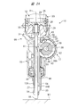
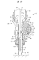
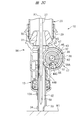
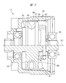
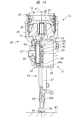
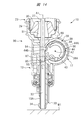
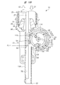
- Embodiment 1 of a driving machine It is a front sectional view showing one embodiment of a driving machine included in the present invention. It is Embodiment 1 of a driving machine, and is a left side sectional view in the state where a hitting part is located in a bottom dead center. It is Embodiment 1 of a driving machine, and is a left side surface sectional view in the state where a hitting part is located in a top dead center. It is Embodiment 1 of a driving machine, and is a left side sectional view just before a hitting part operates toward a bottom dead center from a top dead center. It is front sectional drawing of the conversion part provided in Embodiment 1 of a driving machine. It is a left view which shows the operating state of a conversion part.
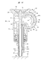
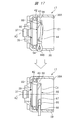
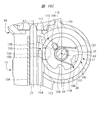
- Embodiment 3 of a driving machine It is a top view of the wheel used for Embodiment 2 of a driving machine. It is Embodiment 3 of a driving machine, and is a left side sectional view in the state where a hitting part is located in a bottom dead center. It is Embodiment 3 of a driving machine, and is a left side surface sectional view in the state where a hitting part is located in a top dead center. It is a bottom sectional view of the conversion part in Embodiment 3 of a driving machine. It is an enlarged view which shows a part of conversion part in Embodiment 3 of a driving machine. It is Embodiment 4 of a driving machine, and is a left side surface sectional view in the state where a hitting part is located in a bottom dead center.
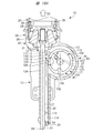
- Embodiment 4 of a driving machine is a front sectional view in the state where a hitting part is located in a bottom dead center. It is Embodiment 4 of a driving machine, and is a left side surface sectional view in the state where a hitting part is located in a top dead center. It is Embodiment 4 of a driving machine, and is a left side sectional view in the state where a hitting part operates toward a bottom dead center from a top dead center. It is Embodiment 4 of a driving machine, and is a front sectional view in the state where a hitting part descended and reached bottom dead center.
- Embodiment 4 of a driving machine and is front sectional drawing which shows the process in which a wire remove
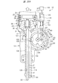
- Embodiment 5 of a driving machine and is the left side surface sectional view in case the circumference of a wire is long and an impact part is located in a bottom dead center.
- Embodiment 5 of a driving machine and is the left side surface sectional view in case the circumference of a wire is long and a hitting part is located in a top dead center.
- It is left side sectional drawing which shows the principal part of Embodiment 5 of a driving machine. It is a figure which shows the whole wire shape in Embodiment 5 of a driving machine.
- Embodiment 5 of a driving machine is the left side surface sectional view in case the circumference of a wire is short and a hitting part is located in a bottom dead center. It is Embodiment 5 of a driving machine, and the perimeter of a wire is short and it is a left side surface sectional view at the time of a hitting part rising from a bottom dead center. It is Embodiment 5 of a driving machine, and is the left side surface sectional view in case the circumference of a wire is short and a hitting part is located in a top dead center. It is another example of Embodiment 5 of a driving machine, and is a left side surface sectional view in case a hitting part is located in a bottom dead center.
- Embodiment 5 of a driving machine is a left side surface sectional view in case a hitting part is located in a top dead center. It is a further another example of Embodiment 5 of a driving machine, and is a left side surface sectional view in case a hitting part is located in a bottom dead center. It is a further another example of Embodiment 5 of a driving machine, and is a left side surface sectional view in case a hitting part is located in a top dead center.
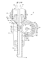
- the driving machine 10 shown in FIGS. 1 and 2 includes a housing 11, a striking unit 12, a nose 96, a power source unit 14, an electric motor 15, a driving unit 63, a speed reduction mechanism 16, and a conversion unit 17.
- the housing 11 includes a cylinder case 18, a handle 19, a head cover 20, a motor case 21, and a connection portion 22.
- the cylinder case 18 is hollow, and the handle 19 is connected to the cylinder case 18.
- the motor case 21 is connected to the cylinder case 18, and the connecting portion 22 is connected to the handle 19 and the motor case 21.
- the head cover 20 is attached so as to cover the opening of the cylinder case 18.
- a cylinder 23 is accommodated in the cylinder case 18.
- a tank 24 is disposed over the cylinder case 18 and the head cover 20.
- the tank 24 has an annular holder 24A and a cap 24B fixed to the holder 24A.
- the holder 24 ⁇ / b> A supports the outer circumferential surface of the cylinder 23 in the radial direction.
- the cylinder case 18 and the head cover 20 are arranged side by side in the direction of the center line A1.
- the cap 24B is disposed in the head cover 20, and the cap 24B and the cylinder 23 are disposed side by side in the direction of the center line A1.
- the cylinder 23 is disposed between the head cover 20 and the nose 96 in the direction of the center line A1.
- the entire arrangement area of the cylinder 23 is located in the arrangement area of the tank 24 in a plan view perpendicular to the center line A1.
- a pressure accumulating chamber 25 is formed across the cylinder 23 and the tank 24.
- the pressure accumulating chamber 25 is filled with a compressible gas.
- a compressible gas in addition to air, an inert gas can be used.
- the inert gas includes nitrogen gas and rare gas. In the present embodiment, an example in which the pressure accumulating chamber 25 is filled with air will be described.
- the striking portion 12 is disposed from the inside of the housing 11 to the outside.
- the striking portion 12 has a piston 26 and a driver blade 27 as shown in FIG. 2A.
- the piston 26 can reciprocate in the direction of the center line A1 within the cylinder 23.
- a seal member 28 is attached to the outer peripheral surface of the piston 26. When the striking portion 12 operates in the direction of the center line A1, the piston 26 and the seal member 28 slide with respect to the inner peripheral surface of the cylinder 23.
- a nose 96 shown in FIG. 1 has an injection portion 13 and a support portion 29.
- the nose 96 is obtained by integrating the injection portion 13 and the support portion 29.
- the nose 96 is made of metal.
- the injection part 13 and the support part 29 are arranged side by side in the direction of the center line A1.
- the support portion 29 is disposed between the ejection portion 13 and the head cover 20 in the direction of the center line A1.
- the support portion 29 has a cylindrical shape, and the support portion 29 is provided in the housing 11.
- the bumper 30 is supported by the support portion 29.
- the bumper 30 may be made of either synthetic rubber or silicon rubber.
- the bumper 30 is annular, and the bumper 30 has a guide hole 31.
- the guide hole 31 is provided around the center line A1.
- the injection unit 13 includes a blade guide 13A shown in FIGS. 2A, 2B, and 2C, and the blade guide 13A forms an injection path 32.
- the injection path 32 is a passage or a guide hole formed along the direction of the center line A1.
- the driver blade 27 can move in the direction of the center line A1 in the injection path 32.
- the blade guide 13A prevents the driver blade 27 from moving in a direction intersecting the center line A1.
- the blade guide 13 ⁇ / b> A has a tip 33.
- the tip 33 is a portion of the blade guide 13A that is farthest from the support portion 29 in the direction of the center line A1.
- a push lever 34 is attached to the injection unit 13. The push lever 34 can move within a predetermined range in the direction of the center line A ⁇ b> 1 with respect to the injection unit 13.
- the striking portion 12 operates in the direction of the center line A1 between the top dead center indicated by a broken line in FIG. 1 and the bottom dead center indicated by a solid line.
- the top dead center of the hitting portion 12 corresponds to the position where the piston 26 is farthest from the bumper 30.
- the bottom dead center of the hitting portion 12 corresponds to the position where the piston 26 contacts the bumper 30.
- the operation direction in which the hitting portion 12 approaches the bumper 30 can be defined as the first direction D1.
- An operation direction in which the striking portion 12 is separated from the bumper 30 can be defined as a second direction D2.
- the first direction D1 and the second direction D2 are opposite to each other.
- the power supply unit 14 illustrated in FIG. 1 can be attached to and detached from the connection unit 22.
- the power supply unit 14 includes a storage case and a plurality of battery cells stored in the storage case.
- As the battery cell for example, a secondary battery can be used.
- the electric motor 15 is disposed in the motor case 21.
- the electric motor 15 includes a rotor 35 and a stator 36. The rotor 35 of the electric motor 15 can rotate forward and backward.
- a gear case 57 is provided in the motor case 21.
- the gear case 57 is made of metal as an example.
- the speed reduction mechanism 16 is provided in the gear case 57.
- An input element of the speed reduction mechanism 16 is coupled to the rotor 35, and an output element of the speed reduction mechanism 16 is connected to the rotation shaft 37.
- the electric motor 15, the speed reduction mechanism 16, and the rotating shaft 37 are arranged concentrically around the center line A2. As shown in FIG. 2A, the center line A1 and the center line A2 do not intersect with each other in a side view perpendicular to the center line A2, and the center line A1 and the center line A2 are spaced apart from each other. .
- a rotation restricting mechanism 97 is provided in the gear case 57.
- the rotation restricting mechanism 97 allows the wheel 39 to rotate clockwise in FIG. 2A with a rotational force when the electric motor 15 rotates forward.
- the rotation restricting mechanism 97 prevents the wheel 39 from rotating counterclockwise.
- the conversion unit 17 is disposed in the housing 11.
- the conversion part 17 is arrange
- the converter 17 converts the rotational force of the rotary shaft 37 into a force that causes the driver blade 27 to operate in the direction of the center line A1.
- the conversion unit 17 includes a casing 38, a wheel 39, a hook guide 40, and a hook 41.
- the casing 38 is made of metal as an example, and the casing 38 is integrated with the nose 96.
- the casing 38 supports the rotating shaft 37 through the bearing 42 so as to be rotatable.
- the cross-sectional shape of the casing 38 is an arc shape.
- the casing 38 forms a storage chamber 43.
- the storage chamber 43 is connected to the injection path 32.
- the inner peripheral surface 38A of the casing 38 has an arc shape centered on the center line A2.
- a stopper 45 is provided so as to protrude inward from the inner peripheral surface 38A.
- the wheel 39 is fixed to the rotating shaft 37.
- the wheel 39 is made of metal or synthetic resin, for example, and is disposed in the storage chamber 43.
- the wheel 39 has a winding groove 46 over the entire circumference in the rotational direction.
- a passage 47 is formed between the winding groove 46 and the inner peripheral surface 38A.
- the passage 47 is arranged in an arc shape with the center line A2 as the center.
- the wheel 39 has a holding groove 48 shown in FIG. 4A.
- the holding groove 48 is provided in a part of the rotation direction of the wheel 39. In a plan view perpendicular to the center line A2, the inner peripheral surface of the holding groove 48 has an arc shape.
- the hook guide 40 is disposed in the accommodation chamber 43.
- the hook guide 40 is a metal plate as an example.
- the hook guide 40 is attached so as not to rotate with respect to the casing 38.
- the hook guide 40 has a recess 49 that is open on the outer peripheral surface, and a protrusion 50 that has the recess 49 formed therein.
- the hook 41 is made of metal as an example, and is disposed in the holding groove 48.
- the outer peripheral surface shape of the hook 41 is circular.
- the hook 41 can rotate around the center line A ⁇ b> 3 in the holding groove 48.
- the center line A3 is parallel to the center line A2.
- the hook 41 includes an engaging portion 51, a groove 52, and a guide portion 53.
- the guide portion 53 is arranged eccentrically from the center line A3 and has an arc shape in plan view perpendicular to the center line A2.
- the driver blade 27 is provided with an attachment portion 54.
- a mounting portion 54 is provided between the tip 55 and the piston 26 in the direction of the center line of the driver blade 27.
- the tip 55 is the portion of the driver blade 27 that is farthest from the piston 26 in the direction of the center line A1. With the piston 26 in contact with the bumper 30, the attachment portion 54 is located between the casing 38 and the tip 33.
- a wire 44 is disposed across the injection path 32 and the storage chamber 43.
- the wire 44 is formed by twisting together a plurality of single materials as an example.
- the single material is made of synthetic resin or metal.
- a combination of multiple materials may be used.
- the wire 44 may be any of a wire, a cable, and a rope.
- the wire 44 has a predetermined tensile strength with respect to a load in the length direction, and has a predetermined flexibility in the length direction.
- a hanging ring 44 ⁇ / b> B is provided at a first end in the length direction of the wire 44, and the hanging ring 44 ⁇ / b> B is hung on the attachment portion 54.
- An engaging portion 56 is attached to the second end portion 44 ⁇ / b> C in the length direction of the wire 44.
- the engaging portion 56 is a ball made of metal or synthetic resin, for example, and the wire 44 is passed through the through hole of the ball.
- the outer diameter of the ball is larger than the outer diameter of the wire 44.
- a part of the wire 44 in the longitudinal direction is disposed in the accommodation chamber 43 regardless of the position of the driver blade 27 in the direction of the center line A1.
- the stopper 45 is disposed between the driver blade 27 and the rotation shaft 37 in a plan view including the center line A1 and perpendicular to the center line A2.
- the stopper 45 is disposed between the support portion 29 and the rotation shaft 37 in the direction of the center line A1.
- the electric motor 15, the speed reduction mechanism 16, and the conversion unit 17 constitute a drive unit 63.
- a rotation amount detection unit 64 is provided in the storage chamber 43.
- the rotation amount detection unit 64 is a Hall element that detects the rotation amount of the wheel 39.
- the magazine 58 shown in FIG. 1 is supported by the nose 96 and the connecting portion 22.
- the magazine 58 accommodates the nails 59.
- a plurality of nails 59 are accommodated in the magazine 58 in a state of being connected in one row.
- the magazine 58 has a feeder, and the feeder supplies the nails 59 in the magazine 58 to the injection path 32 one by one.
- control unit 60 is provided in the housing 11, for example, in the connection unit 22.
- the control unit 60 has a microprocessor attached to the substrate.
- the microprocessor includes an input / output interface, a control circuit, an arithmetic processing unit, and a storage unit.
- An inverter circuit that is electrically connected to the power supply unit 14 and the electric motor 15 is provided in the housing 11.
- the inverter circuit connects and disconnects the stator 36 of the electric motor 15 and the power supply unit 14.
- the inverter circuit includes a plurality of switching elements, and the plurality of switching elements can be turned on / off independently.
- the control unit 60 controls the rotation and stop of the electric motor 15, the rotation speed of the electric motor 15, and the rotation direction of the electric motor 15 by controlling the inverter circuit.
- a trigger sensor 61, a push sensor, and a position detection sensor are provided in the housing 11.
- the push sensor detects whether the push lever 34 is pressed against the workpiece W1 and outputs a signal.
- the trigger sensor 61 is provided in the handle 19, and the trigger sensor 61 outputs a signal corresponding to the operation force applied to the trigger 62.
- the position detection sensor detects the position of the wheel 39 in the rotation direction and outputs a signal. Signals from the trigger sensor 61, push sensor, and position detection sensor are input to the control unit 60.
- the control unit 60 stops the electric motor 15 when it is not possible to detect both that the operating force is applied to the trigger 62 and that the push lever 34 is pressed against the workpiece W1.
- the striking unit 12 is stopped at a predetermined standby position. In the present embodiment, the state where the piston 26 is located at the bottom dead center shown in FIG. 2A is described as the standby position of the striking unit 12.
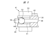
- the engaging portion 56 When the hitting portion 12 is stopped at the standby position, the engaging portion 56 is in contact with the stopper 45. The engaging part 51 is released from the engaging part 56. A part of the wire 44 is located in the groove 52. Moreover, the guide part 53 is contacting the outer peripheral surface of the hook guide 40, as shown to the upper stage in FIG. 4A.
- the control unit 60 detects that the operating force is applied to the trigger 62 and that the push lever 34 is pressed against the workpiece W1, the electric motor 15 is rotated forward. The rotational force of the electric motor 15 is transmitted to the wheel 39 via the speed reduction mechanism 16.
- the tip 55 of the driver blade 27 is positioned between the head portion 59A of the nail 59 and the support portion 29 in the direction of the center line A1, as shown in FIG. 2B. To do. Moreover, the hook 41 approaches the recessed part 49 of the hook guide 40 in the rotation direction of the wheel 39 as shown in the middle part of FIG. 4A.
- the guide portion 53 reaches the outside of the recess 49. Then, by the rotational force applied to the hook 41 from the engaging portion 56, the hook 41 rotates counterclockwise by a predetermined angle around the center line A3 as shown in the lower part of FIG. 4A. That is, a part of the guide portion 53 enters the recess 49. For this reason, as shown in FIG. 2C, the engaging portion 51 is released from the engaging portion 56. The engaging portion 51 and the wire 44 move counterclockwise in the passage 47 in FIG. 2C.
- the striking portion 12 When the engaging portion 51 is released from the engaging portion 56, the striking portion 12 operates in the first direction D1 with the pressure in the pressure accumulating chamber 25. When the striking portion 12 operates in the first direction D1, the driver blade 27 strikes the nail 59 located in the injection path 32, and the nail 59 is driven into the driven material W1. The push lever 34 is separated from the material to be driven W1 by the reaction force of the driver blade 27 hitting the nail 59.
- the control unit 60 processes the signal of the position detection sensor, and stops the electric motor 15 before the hook 41 reaches the stopper 45 in the rotation direction of the wheel 39.
- the entire wire rod 44 and the drive unit 63 are disposed outside the pressure accumulation chamber 25. Therefore, it is possible to prevent the driving machine 10 from increasing in size.
- the region C ⁇ b> 1 is a range in which a part of the pressure accumulating chamber 25 is formed in the cylinder 23 in the radial direction of the cylinder 23.
- a region C ⁇ b> 2 is a range in which the piston 26 slides with respect to the cylinder 23 in the operating direction of the striking portion 12. Therefore, it is possible to suppress the driving machine 10 from increasing in size in the radial direction of the cylinder 23.
- All of the wire rods 44 and the drive unit 63 are provided between the bumper 30 and the tip 33 of the blade guide 13A in the operating direction of the striking unit 12. That is, in the direction of the center line A1, the arrangement region of the injection portion 13 and the arrangement region of the entire wire 44 and the drive portion 63 overlap at least partially. Therefore, it is possible to prevent the driving machine 10 from becoming large in the direction of the center line A1.
- the wire 44 and the engaging portion 56 pass through the passage 47 when the striking portion 12 operates in either the first direction D1 or the second direction D2. Therefore, the enlargement of the conversion unit 17 can be suppressed.
- the driver blade 27 it is not necessary to provide the driver blade 27 with an engaging portion such as a rack. Therefore, the shape and structure of the driver blade 27 can be simplified, and an increase in the weight of the driver blade 27 can be suppressed. Further, since the driver blade 27 is not provided with a rack, the opening diameter of the guide hole 31 of the bumper 30 can be reduced, the outer diameter of the bumper 30 can be reduced, and the inner diameter of the support portion 29 can be reduced. Therefore, the overall size of the driving machine 10 can be reduced. By reducing the opening diameter of the guide hole 31 of the bumper 30, it is possible to suppress a decrease in the rigidity of the bumper 30. Further, since the engaging portion 51 does not engage with the driver blade 27, wear and deformation of the driver blade 27 can be suppressed.
- the maintenance of the components is only the replacement of the wire 44, and it is not necessary to replace the entire striking portion 12 including the driver blade 27 or the wheel 39. Therefore, maintainability is improved. Furthermore, since the wire 44 is disposed outside the elements forming the pressure accumulating chamber 25, the sealing performance of the pressure accumulating chamber 25 can be improved.
- the state where the engaging portion 56 and the engaging portion 51 are engaged can be reliably fixed to a predetermined location in the rotation direction of the wheel 39. Therefore, the position of the top dead center of the striking portion 12 in the direction of the center line A1, that is, the striking portion 12 strikes the nail 59, so that variations in timing at which the engaging portion 51 releases the wire 44 can be suppressed.
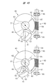
- FIG. 4B is an example in which the adjusting mechanism 90 is provided in the first embodiment of the driving machine 10.
- the adjusting mechanism 90 adjusts the timing at which the engaging portion 51 is released from the engaging portion 56 with respect to the position of the striking portion 12 that operates in the second direction D2 in FIG. 2B.
- the adjustment mechanism 90 includes an adjustment shaft 91 and a sector gear 92.
- a worm 93 is formed on the outer peripheral surface of the adjustment shaft 91, and the worm 93 meshes with the sector gear 92.
- the adjustment shaft 91 has a knob 94.
- the adjustment shaft 91 is supported by the bearing 95 so as to be rotatable about the center line A5.
- the bearing 95 is supported by the casing 38.
- the knob 94 is exposed to the outside of the housing 11.
- the sector gear 92 is fixed to the hook guide 40.
- the hook guide 40 can be actuated and stopped with respect to the casing 38 within a range of a predetermined angle around the center line A2.
- the hook guide 40 rotates about the center line A2.
- the hook guide 40 shown in the upper part of FIG. 4B is rotated clockwise and the hook guide 40 is stopped at the position shown in the lower part of FIG. 4B, the engaging part 51 is moved from the engaging part 56 to the position of the striking part 12.
- the release timing can be changed by the angle ⁇ 1 in the rotation direction of the wheel 39. That is, when the adjustment mechanism 90 is operated, the top dead center of the hitting unit 12 can be changed.
- the wheel 39 has two ribs 65 and 66 that form the winding groove 46.
- the ribs 65 and 66 are provided at intervals in the direction of the center line A2. As shown in FIG. 8, the ribs 65 and 66 are provided over the entire circumference of the wheel 39.
- the rib 65 is provided with an engaging portion 65A
- the rib 66 is provided with an engaging portion 66A.
- the engaging portions 65 ⁇ / b> A and 66 ⁇ / b> A are arranged at the same position in the rotation direction of the wheel 39. In the direction of the center line A2, the interval between the engaging portion 65A and the engaging portion 66A is narrower than the interval between other portions in the winding groove 46.
- the distance between the rib 65 and the rib 66 is narrower than that at other portions.
- the casing 38 has a release claw 67 and a retracting portion 68.
- the release claw 67 protrudes from the inner surface of the casing 38 toward the accommodation chamber 43.
- the stopper 45 and the release claw 67 are located between the rib 65 and the rib 66. When the wheel 39 rotates, the stopper 45 and the release claw 67 pass between the engaging portion 65A and the engaging portion 66A, respectively.
- the release claw 67 is disposed downstream of the inner peripheral surface 38 ⁇ / b> A in the rotation direction of the wheel 39.
- the retracting portion 68 is a recess connected to the inner peripheral surface 38A. A part of the retracting portion 68 is located outside the outer peripheral surface of the wheel 39 in the radial direction of the wheel 39.
- the retracting portion 68 is provided between the release claw 67 and the inner peripheral surface 38 ⁇ / b> A in the rotation direction of the wheel 39.
- the striking portion 12 operates from the top dead center to the bottom dead center with the pressure in the pressure accumulating chamber 25, and the driver blade 27 strikes the nail 59. Further, the wire 44 and the engaging portion 56 are pulled by the driver blade 27 and move in the passage 47 counterclockwise. When the striking portion 12 reaches the bottom dead center as shown in FIG. 7C, the engaging portion 56 comes into contact with the stopper 45 and the wire 44 stops.
- the second embodiment of the driving machine 10 can obtain the same effects as those of the first embodiment of the driving machine 10. Further, the engaging portion 66A provided on the wheel 39 does not operate with respect to the wheel 39, and the configuration is simplified. Therefore, the product body can be reduced in size and weight.
- the conversion unit 17 includes a wheel 69, a lifter guide 70, a lifter 71, a casing 72, and pulleys 73 and 74.
- the casing 72 is integrated with the injection unit 13.
- the casing 72 has a storage chamber 83, and the storage chamber 83 is connected to the injection path 32.
- the wheel 69 is disposed in the accommodation chamber 83.
- the wheel 69 is rotatably supported by the casing 72 around the center line A4.
- the support shaft 75 of the wheel 69 has a bevel gear 76.
- a bevel gear 77 is provided on the rotating shaft 37, and the bevel gear 76 and the bevel gear 77 are engaged with each other.
- the wheel 69 has a holding groove 78 shown in FIG.
- the holding groove 78 is provided in a part of the rotation direction of the wheel 69.
- the inner peripheral surface of the holding groove 78 has an arc shape when viewed from the bottom perpendicular to the center line A4.
- the lifter guide 70 is fixed to the casing 72.
- the hook guide 40 is a metal plate.
- the lifter guide 70 has a concave portion 79 opened on the outer peripheral surface, and a protrusion 80 having the concave portion 79 formed therein.
- the lifter 71 is a metal cylinder.
- the lifter 71 is disposed in the holding groove 78.
- the lifter 71 can rotate around the center line A5 in the holding groove 78.
- Center line A5 is parallel to center lines A1 and A4.
- the lifter 71 includes an engaging portion 81 and a guide portion 82.
- the engaging portion 81 protrudes from the outer peripheral surface of the lifter 71.
- the guide portion 82 is arranged eccentrically from the center line A5 and has an arc shape in a bottom view perpendicular to the center line A5.
- the inner peripheral surface of the casing 72 has an arc shape in a bottom view perpendicular to the center line A4.
- a storage chamber 83 is formed between the outer peripheral surface of the wheel 69 and the inner peripheral surface of the casing 72.
- the pulleys 73 and 74 are disposed in the injection path 32.
- the pulleys 73 and 74 are rotatable.
- the pulleys 73 and 74 are arranged at intervals in the direction of the center line A1.
- the pulley 74 is disposed between the attachment portion 54 and the pulley 73 in the direction of the center line A1.
- the pulleys 73 and 74 are disposed between the driver blade 27 and the wheel 69 in a direction intersecting the center line A1.
- the engaging portion 81 is disposed between the pulley 73 and the pulley 74 in the center line A1 direction.
- a mounting portion 84 is provided on the support portion 29.
- the attachment portion 84 is disposed between the pulley 73 and the bumper 30 in the direction of the center line A1.
- a first end portion of the wire 44 is connected to the attachment portion 54, and a hanging ring 87 provided at the second end portion of the wire 44 is hung on the attachment portion 84.
- a portion between the hanging ring 44 ⁇ / b> B and the hanging ring 87 is hung on the pulleys 73 and 74.
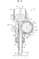
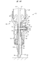
- FIG. 9A when the striking portion 12 is located at the bottom dead center and the wheel 69 is stopped, as shown in the upper part of FIG. It stops at the injection path 32.
- the wire 44 is substantially linear, and the wheel 69 is separated from the wire 44. Further, the guide portion 82 is in contact with the outer peripheral surface of the lifter guide 70.
- the engaging portion 81 engages with a portion 44 ⁇ / b> A located between the pulley 74 and the pulley 74 in the wire 44 and pulls the wire 44. In this way, the wheel 69 takes up the wire 44.
- the wire 44 and the engaging portion 81 pass through the storage chamber 83.
- the striking portion 12 rises from the bottom dead center toward the top dead center, and the pressure in the pressure accumulating chamber 25 rises.
- the engaging portion 81 reaches the position farthest from the pulleys 73 and 74 as shown in the middle stage in FIGS. 9B and 10. Further, the lifter 71 approaches the recess 79 in the rotation direction of the wheel 69.
- the lifter 71 When the guide portion 82 reaches the outside of the recess 79, the lifter 71 is rotated in a counterclockwise direction around the center line A5 as shown in the lower part of FIG. 10 by the rotational force applied to the lifter 71 from the engaging portion 81. Rotate the angle. That is, a part of the guide portion 82 enters the recess 79. For this reason, the engaging part 81 is released from the location 44 ⁇ / b> A of the wire 44. The wire 44 moves counterclockwise in the accommodation chamber 83.
- the striking portion 12 When the engaging portion 81 is released from the wire rod 44, the striking portion 12 operates from the top dead center to the bottom dead center with the pressure in the pressure accumulating chamber 25, and the driver blade 27 strikes the nail 59. Further, the piston 26 collides with the bumper 30 as shown in FIG. 9A. Further, when the wheel 69 stops, the engaging portion 81 comes into contact with the wire rod 44 and stops.
- the third embodiment of the driving machine 10 can obtain the same effects as those of the first embodiment of the driving machine 10.
- Embodiment 3 of the driving machine 10 winds up the intermediate position of the length direction of the wire 44 compared with Embodiment 1 of the driving machine 10. For this reason, the winding amount of the wire 44 with respect to the rotation amount of the wheel 69 is large, the driver blade 27 can be moved to a predetermined position with a small rotation amount of the wheel 69, and the pressure in the pressure accumulating chamber 25 can be increased. In other words, since the amount of rotation of the wheel 69 necessary for winding the wire 44 is small, the radius in the radial direction of the wheel 69 can be designed to be small, and the product body can be reduced in size and weight. Here, the winding amount of the wire 44 is approximately doubled with respect to the rotation amount of the wheel 69.
- both ends of the wire 44 are fixed to the driver blade 27 and the wheel 39, respectively. For this reason, it is not necessary to provide an engaging part in the wire 44 and the nose 96, and the structure is simplified. Therefore, the product body can be reduced in size and weight.
- Embodiment 3 of the driving machine 10 it is also possible to provide an adjustment mechanism 90 shown in FIG. 4B.
- the wheel 39 has an attachment portion 85 and an engagement portion 86.
- the attachment portion 85 is an axis that protrudes from the surface of the wheel 39 in the direction of the center line A2.
- a hanging ring 87 is formed at the end of the wire 44 in the length direction, and the hanging ring 87 is hung on the attachment portion 85. Even if the wheel 39 rotates, the hanging ring 87 does not come off the attachment portion 85.
- the engaging portion 86 is arranged in an arc shape centering on the center line A2 and over a predetermined range in the rotation direction of the wheel 39.
- the range in which the engaging portion 86 is arranged in the rotation direction of the wheel 39 is different from the place where the attachment portion 85 is arranged in the rotation direction of the wheel 39.
- the engaging portion 86 has a support groove 88 and a notch 89.
- the support groove 88 is provided outside the engaging portion 86 in the radial direction of the wheel 39.
- the notch 89 is provided continuously to the support groove 88 in the rotation direction of the wheel 39.
- a passage 47 is formed between the engaging portion 86 and the inner peripheral surface 38A.
- the engaging portion 86 engages with the portion 44 ⁇ / b> A of the wire 44, and the wheel 39 winds the wire 44 in a state where the wire 44 is in contact with the support groove 88.
- the location 44 ⁇ / b> A is in the middle of the attachment portion 85 and the attachment portion 54 in the length direction of the wire 44. In this way, the wheel 39 pulls the wire 44.
- the wire 44 and the engaging portion 86 pass through the storage chamber 83.
- the notch 89 approaches the bumper 30 in the direction of the center line A1 as shown in FIG.
- the portion of the wire 44 that has reached the notch 89 does not engage with the engaging portion 86.
- a part of wire 44 moves so that it may approach the attaching part 85 through the side space E1 of the wheel 39, as shown to the upper stage of FIG.15 and FIG.17.
- the side space E1 is the side of the wheel 39 and the engaging portion 86 in the direction of the center line A2.
- the side space E1 is connected to the passage 47. The position of the passage 47 and the side space E1 is different at least in part in the direction of the center line A2.
- the portion 44 ⁇ / b> A that is engaged with the engaging portion 86 in the wire 44 is also detached from the engaging portion 86.
- the striking unit 12 operates from the top dead center toward the bottom dead center. Further, the hitting unit 12 reaches the bottom dead center as shown in FIG. Further, the entire wire 44 is released from the engaging portion 86 as shown in the lower part of FIGS. 16 and 17.
- the fourth embodiment of the driving machine 10 can obtain the same effects as those of the first embodiment of the driving machine 10.
- both ends of the wire rod 44 are fixed to the driver blade 27 and the wheel 39, respectively, so that the engagement portion is not provided on the wire rod 44 and the nose 96, and the structure is simplified. The Therefore, the product body can be reduced in size and weight.
- the fourth embodiment of the driving machine 10 passes through the side surface of the wheel 39 from the moment when the wire 44 is released from the engaging portion 86. For this reason, when the striking part 12 operates toward the bottom dead center, the frictional resistance between the wheel 39 and the wire 44 is small. Therefore, the influence on the action
- the wheel 100 is fixed to the rotating shaft 37.
- the wheel 100 rotates around the center line A2.
- the wheel 100 has a winding part 101 and a holding groove 102.
- the winding unit 101 is an arcuate outer peripheral surface of the wheel 100.
- the holding groove 102 is provided in a range other than the winding portion 101 in the rotation direction of the wheel 100.
- the holding groove 102 forms a part of a circle in a plane perpendicular to the center line A2.
- the movable piece 103 is disposed in the holding groove 102.
- the movable piece 103 has a substantially cylindrical portion that can be engaged with the holding groove 102 and is made of metal.
- the movable piece 103 can rotate within the holding groove 102 in a plane perpendicular to the center line A2, that is, can rotate.
- the movable piece 103 has a hook 104 and a guide part 105.
- the guide part 105 has an arc surface.
- a hook guide 106 is provided in the storage chamber 43.
- the hook guide 106 can be operated with respect to the casing 38, specifically, can rotate about the center line A2.
- the hook guide 106 has a first restricting portion 107 and a second restricting portion 108.
- the 1st control part 107 is a part of outer peripheral surface of the hook guide 106, and the 1st control part 107 is a circular arc surface centering on the centerline A2.
- the second restricting portion 108 is a groove provided in a part of the outer peripheral surface of the hook guide 106.
- the second restricting portion 108 is provided in a range other than the first restricting portion 107 on the outer peripheral surface of the hook guide 106.
- the hook guide 106 has a guide portion 109.
- the guide part 109 is a hole or a groove provided along the radial direction of the hook guide 106.
- An urging member 116 shown in FIG. 18C is provided in the storage chamber 43, and the urging member 116 urges the hook guide 106 clockwise.
- the biasing member 116 is a metal spring as an example.
- a release lever 110 is provided in the injection unit 13.
- the release lever 110 is disposed between the driver blade 27 and the rotating shaft 37.
- the release lever 110 is supported by the injection unit 13 via the support shaft 111.
- the support shaft 111 is located outside the winding portion 101 of the wheel 100 in the radial direction of the wheel 100.
- the release lever 110 can be operated around the support shaft 111.
- a pin 112 is provided on the release lever 110, and the pin 112 is movable along the guide portion 109.
- the hook guide 106 can be operated within a predetermined angle range about the center line A2 in a state where the pin 112 is engaged with the hook guide 106.
- the urging force of the urging member 116 is transmitted to the release lever 110 via the hook guide 106, and the release lever 110 is urged counterclockwise around the support shaft 111.
- a stopper 128 is provided on the injection unit 13.
- the stopper 128 does not move relative to the injection unit 13.
- the stopper 128 has an engaging portion 113.
- the engaging portion 113 is disposed in the injection path 32. As shown in FIG. 18D, two engaging portions 113 are arranged at intervals in a direction intersecting the center line A1.
- the protrusion 115 is provided on the driver blade 27.
- the protrusion 115 is disposed between the piston 26 and the attachment portion 54 in the operation direction of the driver blade 27.
- the protrusion 115 is disposed in the immediate vicinity of the attachment portion 54 in the operating direction of the driver blade 27.
- An annular wire 114 is disposed in the injection path 32.
- An example of the material of the wire 114 is the same as an example of the material of the wire 44.
- the blade guide 13A moves in a direction where the portion of the wire 114 that does not engage with the hook 104 and does not wind around the wheel 100 intersects the center line A1 in the injection path 32, specifically, Restricts movement in a direction away from the driver blade 27.
- the force of the urging member 116 is transmitted to the release lever 110 via the hook guide 106, and the release lever 110 is pressed against the stopper 128. For this reason, the release lever 110 is stopped, and the hook guide 106 is stopped.
- the imaginary line B1 located in the second restricting portion 108 is in a position parallel to the center line A1.
- the imaginary line B1 intersects with the center line A2. Further, the protrusion 115 is separated from the release lever 110.
- the movable piece 103 is stopped at a position closest to the driver blade 27 in the rotation direction of the wheel 100.
- the guide portion 105 comes into contact with the first restricting portion 107 of the hook guide 106 and stops, and the hook 104 is positioned in the injection path 32.
- the hook 104 is located inside the annular wire 114.
- the wire 114 pulls the striking part 12 against the force applied to the striking part 12 from the pressure accumulating chamber 25, the wire 114 receives a load.
- the load received by the wire 114 is transmitted to the movable piece 103, and the movable piece 103 receives a counterclockwise rotation force in FIG. 18A.
- the guide part 105 is pressed against the first restricting part 107, the movable piece 103 does not rotate.
- the guide portion 105 maintains a state in contact with the first restricting portion 107, and the movable piece 103 revolves around the center line A2.
- the wire 114 moves from the injection path 32 to the accommodation chamber 43 and winds around the winding portion 101 of the wheel 100. Further, when the striking portion 12 is further raised and the projection 115 is separated from the release lever 110, the release lever 110 is stopped and the hook guide 106 is stopped.
- the wire rod 144 is moved and pulled out from the storage chamber 43 to the injection path 32 at the same time as the driver blade 27 is lowered.
- the wheel 100 rotates clockwise while the driver blade 27 is lowered, and the guide portion 105 is pressed against the hook guide 106, so that the movable piece 103 rotates clockwise in FIG. 18B. For this reason, the guide portion 105 is pressed against the first restricting portion 107.
- the movable piece 103 stops at a position closest to the driver blade 27 in the rotation direction of the wheel 100 as shown in FIG. 18A.
- FIG. 19A the operation of the driving machine 10 when the circumference of the wire 114 is shorter than the circumference of the wire 114 shown in FIG. 18A will be described with reference to FIG. 19A.
- the striking portion 12 is stopped at the bottom dead center shown in FIG. 19A, the engaging portion 113 is in contact with the wire 114, and the attachment portion 54 is in contact with the wire 114.
- the positions of the other elements and the positional relationship between the elements are the same as in FIG. 18A.
- the release lever 110 operates clockwise in FIG. 19B around the support shaft 111.
- the release lever 110 is separated from the stopper 128, and the release lever 110 stops at the position shown in FIG. 19C.
- the hook guide 106 operates counterclockwise in FIG. 19B and stops at the position shown in FIG. 19C.
- the hook guide 106 operates counterclockwise, the position of the second restricting portion 108 in the rotation direction of the wheel 100 is changed.
- the imaginary line B2 passing through the second restricting portion 108 and the center line A2 stops at a position displaced by an angle ⁇ 2 with respect to the imaginary line B1.
- the angle ⁇ 2 is an acute angle formed between the virtual line B1 and the virtual line B2.
- the movable piece 103 rotates counterclockwise as shown in FIG. 19C, and the hook 104 releases the wire 114.
- the position of the hitting portion 12 immediately before the hook 104 releases the wire 114 is the top dead center.
- the position of the tip 55 of the driver blade 27 corresponding to the top dead center of the hitting portion 12 is, for example, at the position P2 in the direction of the center line A1.
- the striking portion 12 descends from the top dead center with the pressure in the pressure accumulating chamber 25, and the driver blade 27 strikes the nail 59.
- the wire 144 is pulled out from the storage chamber 43 to the injection path 32 at the same time as the driver blade 27 is lowered.
- the wheel 100 rotates clockwise while the driver blade 27 is descending, and the guide portion 105 is pressed against the hook guide 106, so that the movable piece 103 rotates clockwise in FIG. 19C. For this reason, the guide portion 105 is pressed against the first restricting portion 107.
- the angle at which the wheel 100 rotates from the position where the wheel 100 starts rotating in FIG. 18A until the hook 104 releases the wire 114 as shown in FIG. 18B is the first angle.
- the angle at which the wheel 100 rotates from the position where the wheel 100 starts rotating in FIG. 19A until the hook 104 releases the wire 114 as shown in FIG. 19C is the second angle.
- the first angle is larger than the second angle.
- the first angle is, for example, 280 degrees
- the second angle is, for example, 265 degrees.
- the distance between the position P1 and the position P2 in the direction of the center line A1 can be made as small as possible.
- the difference between the distance L1 from the tip 33 to the position P1 and the distance L2 from the tip 33 to the position P2 can be made as small as possible. Therefore, when the circumference of the wire 114 is different, it is possible to suppress a change in response time from when the operator applies operating force to the trigger 62 until the hitting unit 12 reaches top dead center. Further, when the circumferential lengths of the wire rods 114 are different, it is possible to suppress a change in power that operates in a direction in which the striking portion 12 strikes the nail 59.
- 19C is an example of the position of the tip 55 of the driver blade 27 in the direction of the center line A1.
- the position of the tip 55 of the driver blade 27 in the direction of the center line A1 is determined according to the circumference of the wire 114 and the angle ⁇ 2 shown in FIG. 19C.
- the release lever 110 if the arrangement position of the support shaft 111 is changed between the position where the guide portion 109 and the stopper 128 are in contact with each other, the amount of movement of the guide portion 109 with respect to the operating angle of the release lever 110 can be changed. .
- the solenoid actuator 117 is provided in the housing 11 shown in FIG.
- the solenoid actuator 117 includes a cylinder 118, a plunger 119, and a coil 120.
- the cylinder 118 is fixed in the housing 11.
- the plunger 119 is disposed over the inside and outside of the cylinder 118. Plunger 119 is operable.
- the plunger 119 is made of a magnetic material, for example, iron.
- the coil 120 is provided in the cylinder 118. The coil 120 is obtained by winding a conductive wire.
- a switch 125 is provided in the housing 11. The coil 120 is electrically connected to the switch 125.
- a release lever 121 is disposed over the inside and outside of the casing 38.
- a release lever 121 is connected to the plunger 119.
- the casing 38 has a hole 129, and the release lever 121 is movable in the hole 129.
- a pin 124 is provided at a position of the release lever 121 arranged in the casing 38, and the pin 124 is movable along the guide portion 109.
- a spring 122 is provided outside the cylinder 118, and the spring 122 biases the release lever 121 and the plunger 119.
- the cylinder 118 has a stopper 123, and the plunger 119 biased by the spring 122 comes into contact with the stopper 123 and stops.
- a permanent magnet 126 is attached to the driver blade 27, and a magnetic sensor 127 is provided in the injection unit 13.
- the magnetic sensor 127 detects the strength of the magnetic force of the permanent magnet 126 and outputs a signal corresponding to the detection result.
- the control unit 60 processes the signal of the magnetic sensor 127 to control on / off of the switch 125.
- 20A does not include the release lever 110 and the support shaft 111 shown in FIG. 18A. Further, the driver blade 27 does not include the protrusion 115.
- the hitting portion 12 rises on the same principle as the hitting portion 12 shown in FIG. 18A while the hook 104 is engaged with the wire 114. To do.
- the control unit 60 controls on / off of the switch 125 according to the signal of the magnetic sensor 127.
- a current is supplied from the power supply unit 14 to the solenoid actuator 117.
- the controller 60 turns off the switch 125, no current is supplied to the solenoid actuator 117.
- the control unit 60 controls the solenoid actuator 117 the top dead center of the striking unit 12 can be changed. Specifically, the top dead center of the striking portion 12 is changed according to the circumference of the wire 114.
- the peripheral length of the wire 114 is of two types, long and short, will be described.
- the movable piece 103 When the peripheral length of the wire 114 is long, the movable piece 103 reaches the arrangement position of the second restricting portion 108 in the rotation direction of the wheel 100 before the magnetic sensor 127 detects the permanent magnet 126. Then, the guide part 105 enters the second restricting part 108, the movable piece 103 rotates counterclockwise, and the hook 104 releases the wire 114. Therefore, the striking portion 12 is lowered by the pressure in the pressure accumulating chamber 25.
- the control unit 60 always turns off the switch 125 when the circumference of the wire 114 is long. For this reason, the virtual line B1 is always in a position parallel to the center line A1.
- movement of the conversion part 17 in case the perimeter of the wire 114 is long is the same as the action
- the magnetic sensor 127 detects the permanent magnet 126 and outputs a signal before the movable piece 103 reaches the arrangement position of the second restricting portion 108 in the rotation direction of the wheel 100. . Then, the control unit 60 turns on the switch 125, and the current of the power supply unit 14 is supplied to the solenoid actuator 117. Then, the coil 120 generates a magnetic attraction force, and the plunger 119 operates against the force of the spring 122 and stops after being separated from the stopper 123 as shown in FIG. 20B.
- the operating force of the plunger 119 is transmitted to the pin 124 via the release lever 121, and the hook guide 106 operates counterclockwise and stops. For this reason, the arrangement position of the 2nd control part 108 in the rotation direction of the wheel 100 is changed. As a result, the imaginary line B2 located in the second restricting portion 108 is displaced by the angle ⁇ 2 with respect to the imaginary line B1. Further, the guide part 105 enters the second restricting part 108, the movable piece 103 rotates counterclockwise as shown in FIG. 20B, and the hook 104 releases the wire 114. The position of the hitting portion 12 immediately before the hook 104 releases the wire 114 is the top dead center. The striking unit 12 is lowered from the top dead center by the pressure in the pressure accumulating chamber 25.
- the control unit 60 turns off the switch 125. For this reason, the electric current from the power supply unit 14 to the solenoid actuator 117 is cut off, the plunger 119 is pressed against the stopper 123 by the force of the spring 122, and the plunger 119 stops at the initial position. The operating force of the plunger 119 is transmitted to the pin 124 via the release lever 121. Then, the hook guide 106 operates clockwise in FIG. 20B and stops at the position shown in FIG. 20A.
- the driving machine 10 having the conversion unit 17 shown in FIG. 20A can obtain the same effects as the driving machine 10 having the conversion unit 17 shown in FIG. 18A.
- the hook guide 106 does not rotate with respect to the casing 38.
- the conversion unit 17 illustrated in FIG. 21A does not include the guide unit 109, the release lever 110, the support shaft 111, and the pin 112 illustrated in FIG. 18A.
- the driver blade 27 does not include the protrusion 115.
- the striking portion 12 rises on the same principle as the striking portion 12 shown in FIG. 18A. Further, when the movable piece 103 reaches the arrangement position of the second restricting portion 108 in the rotation direction of the wheel 100, the guide portion 105 enters the second restricting portion 108 with the tension of the wire rod 114. Then, the movable piece 103 rotates counterclockwise as shown in FIG. 21B, and the hook 104 releases the wire 114. For this reason, the striking unit 12 operates from the top dead center toward the bottom dead center.
- the entire wire 114 and the drive unit 63 are provided between the bumper 30 and the tip 33 of the blade guide 13A in the operating direction of the hitting unit 12. That is, in the direction of the center line A1, the arrangement region of the injection unit 13 and the entire region of the wire 11 and the arrangement region of the drive unit 63 overlap at least partially. Therefore, it is possible to prevent the driving machine 10 from becoming large in the direction of the center line A1.
- the driving machine 10 only needs to replace the wire 114 when maintaining parts. That is, it is not necessary to replace the entire striking portion 12 including the driver blade 27 or the wheel 100. Therefore, maintainability is improved. Furthermore, since the wire 114 is disposed outside the elements forming the pressure accumulating chamber 25, the sealing performance of the pressure accumulating chamber 25 can be improved.
- the standby position of the striking unit 12 includes a state in which the piston 26 is located at the bottom dead center, and the piston 26 has a top dead center and a bottom dead center. Or a state where the piston 26 is located at the top dead center.
- the driving machine 10 is an example of a driving machine.
- the nail 59 is an example of a stopper.
- the injection unit 13 is an example of an injection unit.
- the pressure accumulation chamber 25 is an example of a pressure accumulation chamber.
- the hitting unit 12 is an example of a hitting unit.
- the wire 44 is an example of a wire.
- the drive unit 63 is an example of a drive unit.
- the housing 11 is an example of a housing.
- the tank 24 is an example of a casing.
- the cylinder 23 is an example of a cylinder.
- the piston 26 is an example of a piston.
- the bumper 30 is an example of a buffer member.
- the tip 33 is an example of the tip of the injection part.
- the engaging portion 56 and the location 44A are examples of the first engaging portion.
- the wheels 39 and 69 are an example of a winding unit.
- the hook 41, the engaging portions 65A and 66A, and the engaging portions 81 and 86 are examples of the second engaging portion.
- the release claw 67 and the retracting portion 68 are an example of a release mechanism.
- the hook guide 40 and the recess 49 are an example of a restriction mechanism.
- the hanging ring 44B is an example of a first end, and the second end 44C and the hanging ring 87 are examples of a second end.
- the passage 47 is an example of a passage.
- the adjustment mechanism 90 is an example of an adjustment mechanism.
- the first direction D1 is an example of the first direction
- the second direction D2 is an example of the second direction.
- the region C1 is an example of a region where the piston is disposed.
- the region C2 is an example of a region where the piston slides with respect to the cylinder.
- the center line A1 is an example of a center line, and the center line A2 is an example of an axis.
- the driving machine 10 is an example of a driving machine.
- the nail 59 is an example of a stopper.
- the injection unit 13 is an example of an injection unit.
- the pressure accumulation chamber 25 is an example of a pressure accumulation chamber.
- the first direction D1 is an example of a first direction.
- the second direction D2 is an example of the second direction.
- the hitting unit 12 is an example of a hitting unit.
- Wires 44 and 114 are examples of wires.
- the drive unit 63 is an example of a drive unit.
- the housing 11 is an example of a housing.
- the wheels 39 and 100 are an example of a rotating member.
- the hook 41, the engaging portions 66A, 81, 86, and the movable piece 103 are examples of engaging portions.
- the top dead center of the hitting unit 12 is an example of a predetermined position.
- the predetermined position is a position where the stopped hitting unit 12 is operated by a predetermined amount in the second direction.
- the predetermined position only needs to be able to obtain a target hitting power when the hitting unit 12 operates in the first direction D1. That is, the predetermined position may be the same or different in the amount that the striking unit 12 that is stopped is actuated in the second direction. That is, the predetermined position may be the same position or a different position.
- the release levers 110 and 121 are an example of an operation member.
- the hook guide 106 is an example of a guide part.
- the first restriction unit 107 is an example of a first restriction unit.
- the second restriction unit 108 is an example of a second restriction unit.
- the solenoid actuator 117 is an example of an actuator.
- the driving machine of Embodiment 1 has the configurations of claims 1 and 11, respectively.
- the driving machine of the second embodiment has the configurations of claims 1 and 11, respectively.
- the driving machine of the third embodiment has the configurations of claims 1 and 11, respectively.
- the driving machine of the fourth embodiment has the configurations of claims 1 and 11, respectively.
- the driving machine of Embodiment 5 has the configurations of claims 1 and 11, respectively.
- the peripheral length of the wire, the position of the mounting portion in the operating direction of the hitting portion, the position of the tip of the injection portion in the operating direction of the hitting portion are adjusted and changed, and the driving of the fifth embodiment It is also possible for the machine to have the configuration of claim 2.
- the driving machine is not limited to the above embodiment, and various changes can be made without departing from the scope of the driving machine.
- the electric motor may be either a brushed electric motor or a brushless electric motor.
- the power supply unit that supplies power to the electric motor may be either a DC power supply or an AC power supply.
- clockwise and counterclockwise are definitions for convenience. That is, when viewed from the opposite side of 180 degrees, the clockwise direction is counterclockwise and the counterclockwise direction is clockwise.
- the rotating member includes a gear, a pulley, a roller, a rotating shaft, and the like.
- a stepping motor can be used instead of the solenoid.
- the housing includes a hollow casing and a body.
- the engaging part should just be a shape or structure which can be engaged and released with a wire.
- the engaging portion includes a protrusion, a hook, a pin, and the like.
- the actuating member includes a lever, an arm, a plunger, a shaft, and the like.
Landscapes
- Engineering & Computer Science (AREA)
- Mechanical Engineering (AREA)
- Physics & Mathematics (AREA)
- Fluid Mechanics (AREA)
- Portable Nailing Machines And Staplers (AREA)
Abstract
L'invention concerne un outil d'entraînement permettant d'améliorer l'étanchéité d'un accumulateur de pression et d'éviter le problème d'une augmentation de taille. L'outil d'entraînement (10) comprend une section d'éjection (13), un accumulateur de pression (25), une section de frappe (12), une section d'entraînement (63) et un boîtier (11). L'outil d'entraînement (10) comporte un cylindre (23) formant au moins une partie de l'accumulateur de pression (25), et un piston (26) formé dans la section de frappe (12). La section d'entraînement (63) et un matériau de fil (44) sont entièrement disposés à l'extérieur, dans la direction radiale du cylindre (23), d'une région (C1) dans laquelle le piston (26) est agencé, et à l'extérieur d'une région (C2) dans laquelle le piston (26) coulisse dans une direction de fonctionnement de la section de frappe (12) par rapport au cylindre (23).
Priority Applications (2)
| Application Number | Priority Date | Filing Date | Title |
|---|---|---|---|
| JP2020516147A JP7036203B2 (ja) | 2018-04-26 | 2019-03-29 | 打込機 |
| US17/048,616 US11712791B2 (en) | 2018-04-26 | 2019-03-29 | Driving tool |
Applications Claiming Priority (4)
| Application Number | Priority Date | Filing Date | Title |
|---|---|---|---|
| JP2018-085321 | 2018-04-26 | ||
| JP2018085321 | 2018-04-26 | ||
| JP2018-205641 | 2018-10-31 | ||
| JP2018205641 | 2018-10-31 |
Publications (1)
| Publication Number | Publication Date |
|---|---|
| WO2019208104A1 true WO2019208104A1 (fr) | 2019-10-31 |
Family
ID=68295235
Family Applications (1)
| Application Number | Title | Priority Date | Filing Date |
|---|---|---|---|
| PCT/JP2019/014016 Ceased WO2019208104A1 (fr) | 2018-04-26 | 2019-03-29 | Outil d'entraînement |
Country Status (3)
| Country | Link |
|---|---|
| US (1) | US11712791B2 (fr) |
| JP (1) | JP7036203B2 (fr) |
| WO (1) | WO2019208104A1 (fr) |
Families Citing this family (12)
| Publication number | Priority date | Publication date | Assignee | Title |
|---|---|---|---|---|
| CN113070849B (zh) * | 2020-01-06 | 2024-07-19 | 朱益民 | 一种打钉工具 |
| WO2021195188A1 (fr) * | 2020-03-25 | 2021-09-30 | Milwaukee Electric Tool Corporation | Dispositif d'entraînement d'élément de fixation alimenté en énergie |
| JP7739134B2 (ja) * | 2021-10-26 | 2025-09-16 | 株式会社マキタ | 打ち込み工具 |
| JP7099778B1 (ja) * | 2021-11-10 | 2022-07-12 | 株式会社フリーク | 釘打ち機 |
| DE102022104882A1 (de) | 2022-03-02 | 2023-09-07 | Fischerwerke Gmbh & Co. Kg | Setzgerät |
| DE102022104878A1 (de) | 2022-03-02 | 2023-09-07 | Fischerwerke Gmbh & Co. Kg | Setzgerät |
| DE102023100345A1 (de) | 2022-03-02 | 2023-09-07 | Fischerwerke Gmbh & Co. Kg | Setzgerät |
| EP4486538A1 (fr) | 2022-03-02 | 2025-01-08 | fischerwerke GmbH & Co. KG | Outil d'entraînement d'élément de fixation |
| EP4488002A1 (fr) * | 2023-07-05 | 2025-01-08 | Hilti Aktiengesellschaft | Dispositif d'enfoncement |
| EP4488001A1 (fr) * | 2023-07-05 | 2025-01-08 | Hilti Aktiengesellschaft | Dispositif d'enfoncement |
| TWI869998B (zh) * | 2023-08-29 | 2025-01-11 | 匯寬實業有限公司 | 電動釘槍及其操作方法 |
| US20260124726A1 (en) * | 2024-11-07 | 2026-05-07 | Koki Holdings Co., Ltd. | Working machine |
Citations (6)
| Publication number | Priority date | Publication date | Assignee | Title |
|---|---|---|---|---|
| JP2008260124A (ja) * | 2007-04-13 | 2008-10-30 | Hilti Ag | 打込み装置 |
| JP2008264970A (ja) * | 2007-04-24 | 2008-11-06 | Hitachi Koki Co Ltd | 打込機 |
| JP2012236250A (ja) * | 2011-05-11 | 2012-12-06 | Max Co Ltd | 打込工具 |
| JP2015009313A (ja) * | 2013-06-28 | 2015-01-19 | 日立工機株式会社 | 打込機 |
| JP2016047594A (ja) * | 2015-12-04 | 2016-04-07 | 日立工機株式会社 | 打込機 |
| WO2017179491A1 (fr) * | 2016-04-12 | 2017-10-19 | 株式会社マキタ | Outil d'entraînement |
Family Cites Families (2)
| Publication number | Priority date | Publication date | Assignee | Title |
|---|---|---|---|---|
| US8011547B2 (en) * | 2007-10-05 | 2011-09-06 | Senco Brands, Inc. | Fastener driving tool using a gas spring |
| JP5849920B2 (ja) | 2012-09-28 | 2016-02-03 | 日立工機株式会社 | 打込機 |
-
2019
- 2019-03-29 JP JP2020516147A patent/JP7036203B2/ja active Active
- 2019-03-29 US US17/048,616 patent/US11712791B2/en active Active
- 2019-03-29 WO PCT/JP2019/014016 patent/WO2019208104A1/fr not_active Ceased
Patent Citations (6)
| Publication number | Priority date | Publication date | Assignee | Title |
|---|---|---|---|---|
| JP2008260124A (ja) * | 2007-04-13 | 2008-10-30 | Hilti Ag | 打込み装置 |
| JP2008264970A (ja) * | 2007-04-24 | 2008-11-06 | Hitachi Koki Co Ltd | 打込機 |
| JP2012236250A (ja) * | 2011-05-11 | 2012-12-06 | Max Co Ltd | 打込工具 |
| JP2015009313A (ja) * | 2013-06-28 | 2015-01-19 | 日立工機株式会社 | 打込機 |
| JP2016047594A (ja) * | 2015-12-04 | 2016-04-07 | 日立工機株式会社 | 打込機 |
| WO2017179491A1 (fr) * | 2016-04-12 | 2017-10-19 | 株式会社マキタ | Outil d'entraînement |
Also Published As
| Publication number | Publication date |
|---|---|
| US20210146517A1 (en) | 2021-05-20 |
| JP7036203B2 (ja) | 2022-03-15 |
| JPWO2019208104A1 (ja) | 2021-04-22 |
| US11712791B2 (en) | 2023-08-01 |
Similar Documents
| Publication | Publication Date | Title |
|---|---|---|
| JP7036203B2 (ja) | 打込機 | |
| US20240208021A1 (en) | Driving tool with rotating member to move striking unit | |
| JP4986033B2 (ja) | 打込機 | |
| JP7452624B2 (ja) | 打込機 | |
| JP6627990B2 (ja) | 打込機 | |
| WO2018198672A1 (fr) | Dispositif d'entraînement | |
| JP5024727B2 (ja) | 打込機 | |
| JP7115544B2 (ja) | 打込機 | |
| EP3915731B1 (fr) | Machine d'entraînement | |
| JP4968518B2 (ja) | 打込機 | |
| JP2023066961A (ja) | 作業機 | |
| JP2018202519A (ja) | 打込機 | |
| JP2008238290A (ja) | 打込機 | |
| WO2021084993A1 (fr) | Machine d'entraînement | |
| JP2008264970A (ja) | 打込機 | |
| JP2018039064A (ja) | 打込機 | |
| JP2008238293A (ja) | 打込機 | |
| JP2018034267A (ja) | 打込機 | |
| JP2018103291A (ja) | 打込機 | |
| EP4582222A1 (fr) | Machine de travail | |
| CN209411495U (zh) | 一种全自动打线机的线调试机构 | |
| JP4807292B2 (ja) | 打込機 | |
| JP2024108830A (ja) | 作業機及び作業機の製造方法 | |
| JP2025087474A (ja) | 検出ユニットおよび作業機システム | |
| JP2019130624A (ja) | 打込機 |
Legal Events
| Date | Code | Title | Description |
|---|---|---|---|
| 121 | Ep: the epo has been informed by wipo that ep was designated in this application |
Ref document number: 19791554 Country of ref document: EP Kind code of ref document: A1 |
|
| ENP | Entry into the national phase |
Ref document number: 2020516147 Country of ref document: JP Kind code of ref document: A |
|
| NENP | Non-entry into the national phase |
Ref country code: DE |
|
| 122 | Ep: pct application non-entry in european phase |
Ref document number: 19791554 Country of ref document: EP Kind code of ref document: A1 |