WO2019208207A1 - Dispositif de climatisation de véhicule et procédé de commande associé - Google Patents
Dispositif de climatisation de véhicule et procédé de commande associé Download PDFInfo
- Publication number
- WO2019208207A1 WO2019208207A1 PCT/JP2019/015481 JP2019015481W WO2019208207A1 WO 2019208207 A1 WO2019208207 A1 WO 2019208207A1 JP 2019015481 W JP2019015481 W JP 2019015481W WO 2019208207 A1 WO2019208207 A1 WO 2019208207A1
- Authority
- WO
- WIPO (PCT)
- Prior art keywords
- vehicle
- air
- time
- mode
- timer
- Prior art date
- Legal status (The legal status is an assumption and is not a legal conclusion. Google has not performed a legal analysis and makes no representation as to the accuracy of the status listed.)
- Ceased
Links
Images


Classifications
-
- B—PERFORMING OPERATIONS; TRANSPORTING
- B60—VEHICLES IN GENERAL
- B60H—ARRANGEMENTS OF HEATING, COOLING, VENTILATING OR OTHER AIR-TREATING DEVICES SPECIALLY ADAPTED FOR PASSENGER OR GOODS SPACES OF VEHICLES
- B60H1/00—Heating, cooling or ventilating devices
- B60H1/00007—Combined heating, ventilating, or cooling devices
- B60H1/00021—Air flow details of HVAC devices
-
- B—PERFORMING OPERATIONS; TRANSPORTING
- B60—VEHICLES IN GENERAL
- B60H—ARRANGEMENTS OF HEATING, COOLING, VENTILATING OR OTHER AIR-TREATING DEVICES SPECIALLY ADAPTED FOR PASSENGER OR GOODS SPACES OF VEHICLES
- B60H1/00—Heating, cooling or ventilating devices
- B60H1/00642—Control systems or circuits; Control members or indication devices for heating, cooling or ventilating devices
- B60H1/00735—Control systems or circuits characterised by their input, i.e. by the detection, measurement or calculation of particular conditions, e.g. signal treatment, dynamic models
- B60H1/00764—Control systems or circuits characterised by their input, i.e. by the detection, measurement or calculation of particular conditions, e.g. signal treatment, dynamic models the input being a vehicle driving condition, e.g. speed
- B60H1/00778—Control systems or circuits characterised by their input, i.e. by the detection, measurement or calculation of particular conditions, e.g. signal treatment, dynamic models the input being a vehicle driving condition, e.g. speed the input being a stationary vehicle position, e.g. parking or stopping
-
- B—PERFORMING OPERATIONS; TRANSPORTING
- B60—VEHICLES IN GENERAL
- B60H—ARRANGEMENTS OF HEATING, COOLING, VENTILATING OR OTHER AIR-TREATING DEVICES SPECIALLY ADAPTED FOR PASSENGER OR GOODS SPACES OF VEHICLES
- B60H1/00—Heating, cooling or ventilating devices
- B60H1/00642—Control systems or circuits; Control members or indication devices for heating, cooling or ventilating devices
- B60H1/00814—Control systems or circuits characterised by their output, for controlling particular components of the heating, cooling or ventilating installation
- B60H1/00821—Control systems or circuits characterised by their output, for controlling particular components of the heating, cooling or ventilating installation the components being ventilating, air admitting or air distributing devices
- B60H1/00835—Damper doors, e.g. position control
- B60H1/00849—Damper doors, e.g. position control for selectively commanding the induction of outside or inside air
-
- B—PERFORMING OPERATIONS; TRANSPORTING
- B60—VEHICLES IN GENERAL
- B60H—ARRANGEMENTS OF HEATING, COOLING, VENTILATING OR OTHER AIR-TREATING DEVICES SPECIALLY ADAPTED FOR PASSENGER OR GOODS SPACES OF VEHICLES
- B60H1/00—Heating, cooling or ventilating devices
- B60H1/00007—Combined heating, ventilating, or cooling devices
- B60H1/00021—Air flow details of HVAC devices
- B60H2001/00078—Assembling, manufacturing or layout details
- B60H2001/00085—Assembling, manufacturing or layout details of air intake
Definitions
- the present invention relates to a vehicle air conditioner and a control method thereof.
- the vehicle is equipped with a vehicle air conditioner for controlling the environment such as the temperature in the passenger compartment.
- the vehicle air conditioner includes an inside / outside air switching damper for switching between an outside air introduction mode and an inside air circulation mode.
- the valve body posture was set so that the inside / outside air switching damper could introduce outside air into the passenger compartment, and the inside air circulation mode was selected.
- the posture of the valve body is set so that the inside air is introduced and circulated in the passenger compartment.
- the airtightness of the passenger compartment tends to be increased.
- the airtightness of the passenger compartment is enhanced, when the door is closed, the amount of air escaped from the door opening due to the decrease in the opening area of the door is reduced, and the vehicle body other than the door opening Since the amount of air passing through the gap is extremely small, the door is difficult to close. As a result, a half-door state may occur.
- Patent Document 1 A technique for suppressing the occurrence of a half-door state when such a door is closed is disclosed in Patent Document 1.
- the technique disclosed in Patent Document 1 has a configuration that can take an intermediate state that is an intermediate posture between the posture at the time of introducing the outside air and the posture at the time of introducing the inside air with respect to the posture of the valve body of the inside / outside air switching damper.
- the inside / outside air switching damper when the door of the vehicle is opened, the inside / outside air switching damper is set to the above intermediate state, and when the door is closed, the posture of the valve body is set before the door is opened.
- a configuration capable of returning to a state (original state) is employed.
- the object of the present invention is to solve the above-described problems, and it is possible to prevent the door from being insufficiently closed when the door is closed, and immediately after the door is closed. It is an object of the present invention to provide a vehicle air conditioner and a method for controlling the same that can ensure high quietness in a passenger compartment and suppress energy consumption of the vehicle.
- An air conditioner for a vehicle includes an outside air introduction mode for introducing air from outside a vehicle compartment of the vehicle, an inside air circulation mode for circulating air inside the vehicle compartment of the vehicle, the outside of the vehicle compartment of the vehicle, and the vehicle interior of the vehicle.
- An inside / outside air switching unit that can be switched between, an intermediate / outside air switching unit, a door opening / closing detection unit that detects an open / closed state of the door of the vehicle, and the outside air introduction mode and the inside air circulation mode by the vehicle occupant
- An air-conditioning control switch that accepts a selection relating to switching, and information relating to the detection from the door opening / closing detection unit and information relating to the selection from the air-conditioning control switch and execution to the inside / outside air switching unit
- An air-conditioning control unit that issues a command to perform the mode, and the air-conditioning control unit detects the door open state by the door opening / closing detection unit If the door is closed after issuing a command to switch to the intermediate mode to the inside / outside air switching unit, and issuing a command to switch to the intermediate mode. After the elapse of time, a command is issued to return to the mode immediately before issuing the command to switch to the intermediate mode to the inside / outside air switching unit.
- FIG. 3A is a schematic side view showing a state of the inside / outside air switching damper in the outside air introduction mode
- FIG. 3B is a schematic side view showing a state of the inside / outside air switching damper in the inside air circulation mode
- FIG. 3C is a schematic side view showing a state of the inside / outside air switching damper in the intermediate mode.
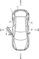
- It is a schematic plan view which shows the vehicle with the door of a driver's seat side in an open state.
- a vehicle 1 includes a vehicle front portion 1a on which a driving power source such as an engine is mounted, a vehicle compartment portion 1b on which an occupant rides, and a vehicle rear portion that is rear of the vehicle compartment portion 1b. 1c.
- the vehicle compartment 1b of the vehicle 1 is provided with doors 2 (a front door 2a, a rear door 2b, and a rear gate 2c) that are opened and closed when passengers get on and off and load and unload luggage.
- FIG. 1 only the left side surface of the vehicle 1 is illustrated, but the front door 2a and the rear door 2b are also provided on the right side surface on the opposite side.
- Each of the front door 2a and the rear door 2b is provided with a window 3 (a front window 3a and a rear window 3b) that is opened and closed by an occupant's operation.
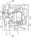
- FIG. 2 is a schematic side view showing the configuration of the inside / outside air switching damper 4 mounted in the A part of FIG. 1, and FIG. 3 (a) shows the inside / outside air when the outside air introduction mode is selected in FIG.
- FIG. 3B is a schematic side view showing the state of the switching damper 4
- FIG. 3B is a schematic side view showing the state of the inside / outside air switching damper 4 when the inside air circulation mode is selected
- FIG. It is a schematic side view which shows the state of the inside / outside air switching damper 4 when the intermediate mode is selected.
- the inside / outside air switching damper 4 includes an outside air introduction port 4a for taking in air from the outside (front) of the vehicle 1, and an inside air introduction port for taking in air from the inside of the passenger compartment 1b. 4b.
- the inside / outside air switching damper 4 includes a valve body 40 at a joining portion of a path continuing from the outside air introduction port 4a and a path continuing from the inside air introduction port 4b.
- the valve body 40 includes a plate-like body 40a and a support arm 40b provided below the plate-like body 40a.
- the plate-like body 40a and the support arm 40b can be rotated integrally around a support shaft 40c that supports the lower portion of the support arm 40b.
- a filter 5 and a blower fan 6 are attached below the inside / outside air switching damper 4. While the blower fan 6 is being driven, the inside / outside air switching damper 4 is introduced with outside air Flow1 that is air outside the vehicle or inside air Flow2 that is air inside the passenger compartment 1b, depending on the state of the valve body 40.
- the introduced outside air Flow1 or inside air Flow2 is air-adjusted through an A / C (air conditioner) (not shown) having a filter 5 and an evaporator, etc., and then adjusted as an air Flow3. It is ejected into the part 1b.
- a / C air conditioner
- spout here means blowing out air.
- the plate-like body 40a of the valve body 40 takes a posture of closing the inside air introduction port 4b.
- the outside air introduction mode is selected, only the outside air Flow1 is introduced into the inside / outside air switching damper 4 from the outside air introduction port 4a.
- the plate-like body 40a of the valve body 40 takes a posture of closing the outside air introduction port 4a.
- the inside air circulation mode is selected, only the inside air Flow2 is introduced into the inside / outside air switching damper 4 from the inside air introduction port 4b.
- the plate-like body 40a of the valve body 40 is in the outside air introduction mode and in the inside air circulation mode. Take an intermediate position posture. Thereby, the outside air introduction port 4a and the inside air introduction port 4b are in a communication state. Therefore, an air circulation path is formed between the space of the vehicle compartment portion 1b and the outside of the vehicle compartment.
- FIG. 4 is a schematic plan view showing the state of the vehicle 1 with the driver seat side door 2ar open.
- the doors 2ar, 2al, 2br, and 2bl are opened and closed when the passenger gets on and off. Further, the rear gate 2c is opened / closed when loading / unloading the vehicle 1 with respect to / from the vehicle.
- the doors 2ar, 2al, 2br, 2bl and the rear gate 2c are There are cases where opening and closing is performed with a time shift (ie, at different timings).
- door opening / closing sensors are provided at the support portions of the doors 2ar, 2al, 2br, 2bl and the rear gate 2c.
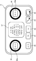
- FIG. 5 is a schematic diagram showing the configuration of the air conditioning control switch 8.
- the air conditioning control switch 8 includes an A / C (air conditioner) switch 80, air volume switches 81 and 82, an outside air introduction switch 83, an inside air circulation switch 84, and a set temperature switching dial 85. , 86 and an air conditioning information display 87.
- a / C air conditioner
- the A / C switch 80 is a switch for selecting whether or not the occupant drives the A / C.
- a / C switch 80 is pressed once, A / C is turned on, and when it is pushed again, A / C is turned off.
- the auto mode is set as the initial state.
- the air volume switches 81 and 82 are switches for the passenger to adjust the air volume, and when the air volume switch 81 is pressed, the air volume increases in order according to the number of times. On the other hand, when the air volume switch 82 is pressed, the air volume decreases in accordance with the number of times.
- the outside air introduction switch 83 is a switch for selecting the outside air introduction mode when the occupant presses the switch.
- the inside air introduction switch 84 is a switch for selecting the inside air circulation mode when the occupant presses the switch.
- One of the outside air introduction switch 83 and the inside air introduction switch 84 is selected by the occupant, whereby the mode can be switched alternatively.
- the set temperature switching dial 85 is a dial for setting the temperature on the right side (in the case of a right-hand drive vehicle, the driver's seat side and in the case of a left-hand drive vehicle) in the passenger compartment 1b.
- the set temperature switching dial 85 is provided with a set temperature display portion 85a for displaying the current set temperature.
- the set temperature switching dial 86 is a dial for setting the temperature on the left side (in the case of a right-hand drive vehicle, on the passenger seat side and in the case of a left-hand drive vehicle) in the passenger compartment 1b. .
- the set temperature switching dial 86 is also provided with a set temperature display portion 86a for displaying the current set temperature.
- the air-conditioning information display 87 is disposed between the set temperature switching dial 85 and the set temperature switching dial 86, and indicates whether the A / C is in an ON state, whether it is in an auto mode, and each The detected temperature and fan air volume are displayed.
- FIG. 6 is a block diagram showing a control configuration related to the vehicle air conditioner 100.
- the vehicle air conditioner 100 includes a control unit 9, an air conditioning control switch 8, a door opening / closing sensor 11, an inside / outside air switching damper 4 including a damper switching actuator 41, And an IG (ignition) switch 10 for starting the engine.
- a control unit 9 an air conditioning control switch 8
- a door opening / closing sensor 11 an inside / outside air switching damper 4 including a damper switching actuator 41
- IG (ignition) switch 10 for starting the engine.
- the control unit 9 has a microprocessor composed of a CPU, a ROM, a RAM, and the like. As shown in FIG. 6, the control unit 9 includes a first timer 9a, a second timer 9b, and a memory 9c.
- the first timer 9a is a timer in which the time from the start of time measurement (that is, time measurement) to the time-up (time-up: state or end of time is up) is set to Ta in advance.
- the second timer 9b is configured to start timing from the time when the first timer 9a finishes timing, and is a timer in which the time from the start of timing to the time-up is set to Tb in advance.
- Ta and Tb are set to satisfy the following relationship.
- Ta is 3 to 7 sec. (For example, 5 sec.) Is set, and Tb is set to 20 to 40 sec. (For example, 30 sec.) Is set.
- the set value of Ta is a period in which the occupant feels quietness immediately after entering the vehicle 1 and closing the door 2, and is a value specified experimentally and empirically.
- the set value of Tb is a period required for another occupant to board after an arbitrary occupant enters the vehicle 1, and this is also a value specified experimentally and empirically.
- the control unit 9 may monitor the use condition of a vehicle, and may adjust Tb so that it may become an optimal value. In that case, AI technology may be used.
- information from the air conditioning control switch 8 ON / OFF information from the IG switch 10, information on opening / closing of the door 2 from the door opening / closing sensor 11, etc. are input to the control unit 9. It has come to be.
- the door opening / closing sensor 11 is provided on each support portion of the doors 2ar, 2al, 2br, 2bl and the rear gate 2c.
- the control unit 9 executes drive control of the damper switching actuator 41 as necessary based on the various information input as described above.
- the damper switching actuator 41 is provided for driving the valve body 40. Based on a command from the control unit 9 to the damper switching actuator 41, the inside / outside air switching damper 4 is selectively switched to any one of the outside air introduction mode, the inside air circulation mode, and the intermediate mode.
- FIG. 7 is a flowchart showing an air conditioning control method executed by the control unit 9
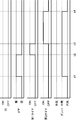
- FIGS. 8 and 9 are time charts showing an example of the air conditioning control method.
- the control unit 9 first determines whether or not the IG switch 10 is in an OFF state (step S1). If it is determined that the IG switch 10 is in the ON state (step S1: No), the air conditioning control is returned to the start.
- step S2 determines whether or not the door 2 is open.
- the door 2 to be determined in step S2 is any one of the doors 2ar, 2al, 2br, and 2bl.
- step S3 the control unit 9 issues a command to the damper switching actuator 41 to switch the inside / outside air switching damper 4 to the intermediate mode.
- step S ⁇ b> 3 when executing the step S ⁇ b> 3, the control unit 9 performs a mode immediately before switching to the intermediate mode, i.e., before switching to the intermediate mode, the occupant controls the air conditioning control switch 8.
- the information related to the input mode (the outside air introduction mode or the inside air circulation mode) is stored in the memory 9c.
- step S4 determines whether any one of the doors 2 is closed (step S4).
- the control unit 9 waits in this state until it is determined that any one of the doors 2 is closed (step S4: No).
- step S4 determines that any one of the doors 2 is closed
- step S5 the control unit 9 starts measuring time with the first timer 9a (step S5).
- step S6 the control unit 9 confirms that the IG switch 10 remains in the OFF state.
- Step S7 Yes
- the determination in Step S6 is continued, and the process waits until the time Ta elapses.
- Step S6 determines that the count time T1 has reached the time Ta in Step S6 (Step S6: No), or when it is determined in Step S7 that the IG switch 10 is turned on. (Step S7: No), the first timer 9a is reset (Step S8), and then the time measurement by the second timer 9b is started (Step S9).
- the control unit 9 stands by until the count time T2 in the second timer 9b reaches a preset time Tb (step S10: Yes).
- step S10 When the control unit 9 determines that the count time T2 in the second timer 9b has reached the time Tb (step S10: No), the control unit 9 resets the second timer 9b (step S11) and stores it in the memory 9c. The stored mode information is read out, and a command is issued to the damper switching actuator 41 so as to switch the mode of the inside / outside air switching damper 4 to the mode immediately before executing step 3 (step S12).
- the IG switch 10 is maintained in the OFF state.
- any one of the doors 2 is opened.
- the control unit 9 switches the inside / outside air switching damper 4 to the intermediate mode.
- the inside / outside air switching damper 4 is set to the inside air circulation mode at a time point before the timing t1.
- the control unit 9 first turns on the first timer 9a and starts measuring time.
- the first timer 9a times up at timing t3. That is, the period from the timing t2 to the timing t3 is the time Ta set in advance for the first timer 9a.
- the control unit 9 turns on the second timer 9b and starts measuring time.
- the second timer 9b times up at timing t4. That is, the period from the timing t3 to the timing t4 is a time Tb set in advance for the second timer 9b.
- the control unit 9 returns the inside / outside air switching damper 4 to the inside air circulation mode at the timing t4 when the second timer 9b has timed up.
- step S7 No
- the control for starting the time measurement of the second timer 9b and then returning the mode of the inside / outside air switching damper 4 will be described with reference to the time chart of FIG.
- the timing control is the same as in the first control example up to timing t ⁇ b> 2, so the description below is omitted.
- the control unit 9 detects that the IG switch 10 is turned on at the timing t5
- the control unit 9 ends the time measurement by the first timer 9a halfway, and the second timer 9b. Start timing. This is because it is considered that it is less necessary to maintain the quietness in the passenger compartment 1b when the occupant who has entered the vehicle 1 turns on the IG switch 10.
- the second timer 9b is timed up at timing t6.
- the period from timing t5 to timing t6 is a time Tb preset for the second timer 9b.
- the control unit 9 returns the inside / outside air switching damper 4 to the inside air circulation mode at the timing t6 when the second timer 9b has timed up.
- the inside / outside air switching damper 4 is returned to the inside air circulation mode at the timings t4 and t6. This is the same mode as before the timing t1. Is. Therefore, when the mode before timing t1 is the outside air introduction mode, the mode is returned to the outside air introduction mode at timings t4 and t6.
- the state where the plate-like body 40a takes a substantially horizontal posture is taken as an example of the intermediate mode, but the present invention is not limited to this.
- the posture of the plate-like body 40a may be controlled so that the outside air introduction port 4a and the inside air introduction port 4b communicate with each other.
- the inside / outside air switching damper 4 adopts a configuration in which the mode is switched by the rotation of the plate-like body 40a.
- the present invention is not limited to this.
- a so-called rotary damper structure can also be employed.
- a configuration is provided in which dampers for individually adjusting the opening degree of the outside air introduction port 4 a and the inside air introduction port 4 b in three stages (that is, fully closed, half open, and fully open) are provided. May be adopted.
- control unit 9 includes the two timers 9a and 9b, and waits for the first timer 9a to finish counting.
- the second timer 9b starts counting, but the present invention is not limited to this.
- the control unit may include only one timer, and when the one timer expires, the inside / outside air switching damper mode may be returned to the original mode.
- the configuration includes only one timer
- the second control example at the timing when the information that the IG switch 10 is turned on is input, The same control as described above can be executed by performing the process of changing the time measurement.
- step S7 when it is determined in the flowchart of FIG. 7 that the IG switch 10 has been turned ON in the determination of step S7 (step S7: No), the time measurement by the first timer T1 is terminated, Time measurement with the two timer T2 is started (step S9).
- the vehicle air conditioner includes an outside air introduction mode for introducing air from outside the vehicle compartment of the vehicle, an inside air circulation mode for circulating air inside the vehicle compartment of the vehicle, the outside of the vehicle compartment of the vehicle, and the vehicle.
- An inside / outside air switching unit capable of switching between an intermediate mode for communicating with the room, a door open / close detection unit for detecting an open / closed state of the door of the vehicle, and the outside air introduction mode and the inside air by the vehicle occupant.
- An air conditioning control switch that accepts a selection related to switching to the circulation mode, information related to the detection from the door opening / closing detection unit, and information related to the selection from the air conditioning control switch, and to the inside / outside air switching unit
- An air conditioning control unit that issues a command for a mode to be executed, wherein the door opening / closing detection unit opens the door.
- a command to switch to the intermediate mode is issued to the inside / outside air switching unit, and after the command to switch to the intermediate mode is issued, the door is closed.
- a command is issued to return to the mode immediately before the command to switch to the intermediate mode is issued to the inside / outside air switching unit.
- the inside / outside air switching unit is set to the intermediate mode when the door is opened, and the intermediate mode is maintained even when the door is closed. Therefore, even in a vehicle with high airtightness in the passenger compartment, it is possible to prevent the door from being closed insufficiently (so-called half-door state) when the door is closed.
- the mode of the inside / outside air switching unit is not returned immediately after the door is closed, but after waiting for the set time to pass, the original mode (command to switch to the intermediate mode is issued). Return to the mode immediately before departure. For this reason, the quietness of the passenger compartment immediately after the occupant gets into the vehicle and closes the door is maintained, and the occupant who gets in does not feel bothered by the sound related to the driving of the internal / external air cut section.
- the mode of the inside / outside air switching unit is returned to the original mode after waiting for the set time to elapse, so even when a plurality of passengers get on and off the vehicle,
- the vehicle air conditioner according to the above aspect, it is possible to prevent the door from closing insufficiently when the door is closed, and to ensure high quietness in the vehicle interior immediately after the door is closed, and The energy consumption of the vehicle can be suppressed.
- preset time refers to the time from when an occupant gets into the vehicle until the start of some operation in the passenger compartment, the time required for multiple occupants to enter, This time is calculated and set automatically.
- the air conditioning control unit includes a first timer and a second timer, and the first timer includes the door opening / closing detection unit. Time counting starts when the closed state of the door is detected, the second timer starts time counting when the first timer expires, and the air conditioning control unit determines that the second timer is timed. When the time is up, the inside / outside air switching unit is instructed to return to the mode selected by the occupant, and the time from the start of time measurement by the first timer to the time up and from the start of time measurement by the second timer The time obtained by adding up the time up to the time-up is the preset time.
- the air conditioning control unit has the first timer and the second timer, and the second timer starts timing after the first timer expires. After the door is closed, the internal / external air switching unit returns to the original mode after the total time of both timers has elapsed.
- the set time from the start of timing of the first timer to the time up is the time when the occupant feels quietness immediately after getting on
- the set time from the start of timing of the second timer to the time up is one person This is the time required for another passenger to get on after the passenger gets on. Both times are calculated and set experimentally and empirically.
- the two timers are used to prevent the occupant who rides from feeling quiet, and even when a plurality of occupants get on the vehicle, Energy consumption can be reduced.
- the vehicle air conditioner is the ignition state detection unit that detects whether the ignition switch is in an ON state or an OFF state in the above aspect, and sends the detection information to the air conditioning control unit.
- the air conditioning control unit further includes a first timer and a second timer, and the first timer counts time from when the door open / close detection unit detects the closed state of the door.
- the timing is terminated, and the second timer starts timing from the time when the first timer finishes timing.
- the control unit issues a command to the inside / outside air switching unit to return to the mode selected by the occupant, and the control by the first timer is performed. Time to count end from the start time and to the time-up from the count start by the second timer, the time obtained by adding the a predetermined time.
- the air conditioning control unit has a first timer and a second timer, and the second timer starts counting after the first timer expires.
- the timing of the first timer is immediately terminated and the timing of the second timer is started. This is because when the passenger turns on the ignition, it is not necessary to feel the quietness in the passenger compartment. For this reason, in the vehicle air conditioner according to the above aspect, it is possible to reduce unnecessary waiting time (waiting time in the intermediate mode) and to return to the mode intended by the occupant earlier. .
- the set time (first set time) from the start of timing to the time-up in the first timer is from the start of timing in the second timer. It is shorter than the set time until the time is up (second set time).
- the first set time is shorter than the second set time. This is because the time required for the occupant who feels the vehicle to feel quiet is shorter than the time required for the other passengers to complete the ride. Note that the difference between the first set time and the second set time is also defined experimentally and empirically.
- a control method for a vehicle air conditioner includes an outside air introduction mode for introducing air from outside the vehicle cabin, an inside air circulation mode for circulating air inside the vehicle cabin, and the vehicle
- An inside / outside air switching unit capable of switching between an intermediate mode in which the outside of the vehicle interior and the vehicle interior communicate with each other, a door open / close detecting unit for detecting an open / closed state of the door of the vehicle, and the outside air by the vehicle occupant
- An air-conditioning control switch that receives a selection related to switching between the introduction mode and the inside-air circulation mode, and when the door open / close detection unit detects an open state of the door, The intermediate mode is switched to the intermediate mode by executing the intermediate mode switching step and the intermediate mode switching step.
- the intermediate mode is maintained even when the door is closed by executing the intermediate mode switching step. Therefore, even in a vehicle with high airtightness in the passenger compartment, it is possible to prevent the door from being closed insufficiently (so-called half-door state) when the door is closed.
- the mode of the inside / outside air switching unit is not returned to the original mode immediately after the door is closed, but after waiting for a preset time (waiting step). ), The mode is returned to the original mode (the mode immediately before the intermediate mode is executed) (the mode return step is executed). For this reason, the quietness of the passenger compartment immediately after the occupant gets into the vehicle and closes the door is maintained, and the occupant who gets in does not feel bothered by the sound related to the driving of the inside / outside air switching unit.
- the mode return step is executed after the standby step. Therefore, even if a plurality of passengers get on and off the vehicle, As in the technique disclosed in No. 1, it is possible to suppress the internal / external air switching unit from being intermittently driven, and to reduce the energy consumption of the vehicle.
- control method for a vehicle air conditioner it is possible to prevent the door from being closed insufficiently when the door is closed, and to ensure high quietness in the vehicle interior immediately after the door is closed. In addition, energy consumption of the vehicle can be suppressed.
Landscapes
- Physics & Mathematics (AREA)
- Thermal Sciences (AREA)
- Engineering & Computer Science (AREA)
- Mechanical Engineering (AREA)
- Air-Conditioning For Vehicles (AREA)
Abstract
L'invention concerne : un dispositif de climatisation de véhicule qui peut empêcher une fermeture de porte incomplète et assurer une parfaite tranquillité à l'intérieur du véhicule immédiatement après fermeture de porte et qui permet de réduire la consommation d'énergie du véhicule ; et un procédé de commande du dispositif de climatisation de véhicule. Le dispositif de climatisation de véhicule (100) comprend : un amortisseur de commutation d'air intérieur et extérieur comprenant un actionneur de commutation d'amortisseur (41) ; un commutateur de commande de climatisation (8) ; une unité de commande (9) ; et un capteur d'ouverture/fermeture de porte (11). L'unité de commande (9) comprend deux minuteries, à savoir des minuteries (9a et 9b) et une mémoire (9c). L'unité de commande (9) règle l'amortisseur de commutation d'air intérieur et extérieur dans un mode intermédiaire lorsqu'une porte s'ouvre tandis qu'un commutateur IG (10) est éteint, puis démarre, dans l'ordre, les minuteries (9a et 9b) lorsque la porte se ferme et, une fois les temps définis par les minuteries (9a et 9b) écoulés, règle l'amortisseur de commutation d'air intérieur et extérieur dans l'état identique à celui avant l'ouverture de la porte.
Priority Applications (1)
| Application Number | Priority Date | Filing Date | Title |
|---|---|---|---|
| US17/048,037 US11491845B2 (en) | 2018-04-24 | 2019-04-09 | Air-conditioning apparatus for vehicle and control method of the same |
Applications Claiming Priority (2)
| Application Number | Priority Date | Filing Date | Title |
|---|---|---|---|
| JP2018-082738 | 2018-04-24 | ||
| JP2018082738A JP7124418B2 (ja) | 2018-04-24 | 2018-04-24 | 車両用空調装置およびその制御方法 |
Publications (1)
| Publication Number | Publication Date |
|---|---|
| WO2019208207A1 true WO2019208207A1 (fr) | 2019-10-31 |
Family
ID=68293618
Family Applications (1)
| Application Number | Title | Priority Date | Filing Date |
|---|---|---|---|
| PCT/JP2019/015481 Ceased WO2019208207A1 (fr) | 2018-04-24 | 2019-04-09 | Dispositif de climatisation de véhicule et procédé de commande associé |
Country Status (3)
| Country | Link |
|---|---|
| US (1) | US11491845B2 (fr) |
| JP (1) | JP7124418B2 (fr) |
| WO (1) | WO2019208207A1 (fr) |
Families Citing this family (1)
| Publication number | Priority date | Publication date | Assignee | Title |
|---|---|---|---|---|
| JP7124418B2 (ja) * | 2018-04-24 | 2022-08-24 | マツダ株式会社 | 車両用空調装置およびその制御方法 |
Citations (10)
| Publication number | Priority date | Publication date | Assignee | Title |
|---|---|---|---|---|
| JPS63201812U (fr) * | 1987-06-19 | 1988-12-26 | ||
| JPH0372007U (fr) * | 1989-11-17 | 1991-07-22 | ||
| JPH0496511U (fr) * | 1991-01-30 | 1992-08-20 | ||
| JPH0563918U (ja) * | 1992-02-05 | 1993-08-24 | アラコ株式会社 | 車両の車内空気圧逃がし装置 |
| JPH0632121U (ja) * | 1992-10-02 | 1994-04-26 | アラコ株式会社 | 車両用換気装置 |
| JPH10147139A (ja) * | 1996-11-20 | 1998-06-02 | Central Motor Co Ltd | 車室内気圧上昇防止装置 |
| JP2002370516A (ja) * | 2001-06-15 | 2002-12-24 | Mitsubishi Motors Corp | 窓開閉連動式空調装置 |
| JP2005254933A (ja) * | 2004-03-10 | 2005-09-22 | Denso Corp | 車両用空調装置 |
| US20080115517A1 (en) * | 2006-11-20 | 2008-05-22 | Nissan Technical Center North America, Inc. | Vehicle Door Closing Energy Reduction Through HVAC Mode Door Control |
| JP2015039995A (ja) * | 2013-08-23 | 2015-03-02 | ダイハツ工業株式会社 | 自動車 |
Family Cites Families (6)
| Publication number | Priority date | Publication date | Assignee | Title |
|---|---|---|---|---|
| US20120077426A1 (en) * | 2009-01-26 | 2012-03-29 | Ford Global Technologies, Llc | Variable HVAC Airflow Control |
| US9656534B2 (en) * | 2013-03-14 | 2017-05-23 | Ford Global Technologies, Llc | Vehicle door closure cabin pressure relief system |
| US10173493B2 (en) * | 2015-12-04 | 2019-01-08 | Ford Global Technologies, Llc | Air extractor system to mitigate vacuum-effect in a passenger compartment of a motor vehicle |
| JP6969985B2 (ja) * | 2017-11-14 | 2021-11-24 | トヨタ自動車株式会社 | 車両用空調装置 |
| JP7124418B2 (ja) * | 2018-04-24 | 2022-08-24 | マツダ株式会社 | 車両用空調装置およびその制御方法 |
| US11260722B2 (en) * | 2019-02-18 | 2022-03-01 | Toyota Motor Engineering & Manufacturing North America, Inc. | System and methods for reducing air pressure in a cabin of a vehicle to assist in door closure |
-
2018
- 2018-04-24 JP JP2018082738A patent/JP7124418B2/ja active Active
-
2019
- 2019-04-09 US US17/048,037 patent/US11491845B2/en active Active
- 2019-04-09 WO PCT/JP2019/015481 patent/WO2019208207A1/fr not_active Ceased
Patent Citations (10)
| Publication number | Priority date | Publication date | Assignee | Title |
|---|---|---|---|---|
| JPS63201812U (fr) * | 1987-06-19 | 1988-12-26 | ||
| JPH0372007U (fr) * | 1989-11-17 | 1991-07-22 | ||
| JPH0496511U (fr) * | 1991-01-30 | 1992-08-20 | ||
| JPH0563918U (ja) * | 1992-02-05 | 1993-08-24 | アラコ株式会社 | 車両の車内空気圧逃がし装置 |
| JPH0632121U (ja) * | 1992-10-02 | 1994-04-26 | アラコ株式会社 | 車両用換気装置 |
| JPH10147139A (ja) * | 1996-11-20 | 1998-06-02 | Central Motor Co Ltd | 車室内気圧上昇防止装置 |
| JP2002370516A (ja) * | 2001-06-15 | 2002-12-24 | Mitsubishi Motors Corp | 窓開閉連動式空調装置 |
| JP2005254933A (ja) * | 2004-03-10 | 2005-09-22 | Denso Corp | 車両用空調装置 |
| US20080115517A1 (en) * | 2006-11-20 | 2008-05-22 | Nissan Technical Center North America, Inc. | Vehicle Door Closing Energy Reduction Through HVAC Mode Door Control |
| JP2015039995A (ja) * | 2013-08-23 | 2015-03-02 | ダイハツ工業株式会社 | 自動車 |
Also Published As
| Publication number | Publication date |
|---|---|
| US11491845B2 (en) | 2022-11-08 |
| JP7124418B2 (ja) | 2022-08-24 |
| US20210155076A1 (en) | 2021-05-27 |
| JP2019188974A (ja) | 2019-10-31 |
Similar Documents
| Publication | Publication Date | Title |
|---|---|---|
| JP2009292293A (ja) | 車両用空調装置 | |
| JP4886786B2 (ja) | オープンカー用冷暖房システム | |
| WO2019208207A1 (fr) | Dispositif de climatisation de véhicule et procédé de commande associé | |
| JP7147244B2 (ja) | 車両用空調装置およびその制御方法 | |
| WO2019208208A1 (fr) | Dispositif de climatisation de véhicule et son procédé de commande | |
| JP7225558B2 (ja) | 車両用空調装置およびその制御方法 | |
| US20210260960A1 (en) | Fully Variable and Integral Aeration Flap Controller | |
| KR20130021907A (ko) | 차량용 공조장치 | |
| JP2019188831A (ja) | 車両用空調装置およびその制御方法 | |
| JP7548842B2 (ja) | 車両用マニュアルエアコンの制御システム | |
| JPH08142648A (ja) | 車両用換気装置 | |
| KR0143162B1 (ko) | 자동차의 차내온도 자동제어방법 | |
| JPH0719864Y2 (ja) | 居眠り予防装置付き自動車用空気調和装置 | |
| KR100888346B1 (ko) | 전자동 온도 조절 시스템의 템프 도어 제어방법 | |
| JPH0641243B2 (ja) | カーエアコン制御装置 | |
| KR20120016329A (ko) | 차량용 공조장치 | |
| KR200389065Y1 (ko) | 차량의 댐퍼 조절용 자동 온도 조절장치 | |
| JP7009704B2 (ja) | 車両の空調制御装置 | |
| JP7089691B2 (ja) | 車両用空調制御装置 | |
| JP2006232007A (ja) | 車両用空調装置 | |
| JP2007137342A (ja) | 車両用空調装置 | |
| JPH036488Y2 (fr) | ||
| JP2510905Y2 (ja) | 自動車用空気調和機の吹出口モ―ド制御装置 | |
| KR101730869B1 (ko) | 겨울철 초기 시동 시의 차량용 공조장치 제어방법 | |
| KR20220072489A (ko) | 차량용 듀얼 송풍 장치, 이의 제어 시스템 및 방법 |
Legal Events
| Date | Code | Title | Description |
|---|---|---|---|
| 121 | Ep: the epo has been informed by wipo that ep was designated in this application |
Ref document number: 19793280 Country of ref document: EP Kind code of ref document: A1 |
|
| NENP | Non-entry into the national phase |
Ref country code: DE |
|
| 122 | Ep: pct application non-entry in european phase |
Ref document number: 19793280 Country of ref document: EP Kind code of ref document: A1 |