WO2019208262A1 - Tissu tubulaire et matériau de base à usage médical mettant en œuvre un tel tissu tubulaire - Google Patents
Tissu tubulaire et matériau de base à usage médical mettant en œuvre un tel tissu tubulaire Download PDFInfo
- Publication number
- WO2019208262A1 WO2019208262A1 PCT/JP2019/015929 JP2019015929W WO2019208262A1 WO 2019208262 A1 WO2019208262 A1 WO 2019208262A1 JP 2019015929 W JP2019015929 W JP 2019015929W WO 2019208262 A1 WO2019208262 A1 WO 2019208262A1
- Authority
- WO
- WIPO (PCT)
- Prior art keywords
- tubular
- fabric
- woven fabric
- weft
- outer diameter
- Prior art date
- Legal status (The legal status is an assumption and is not a legal conclusion. Google has not performed a legal analysis and makes no representation as to the accuracy of the status listed.)
- Ceased
Links
Images


Classifications
-
- D—TEXTILES; PAPER
- D03—WEAVING
- D03D—WOVEN FABRICS; METHODS OF WEAVING; LOOMS
- D03D15/00—Woven fabrics characterised by the material, structure or properties of the fibres, filaments, yarns, threads or other warp or weft elements used
- D03D15/20—Woven fabrics characterised by the material, structure or properties of the fibres, filaments, yarns, threads or other warp or weft elements used characterised by the material of the fibres or filaments constituting the yarns or threads
- D03D15/283—Woven fabrics characterised by the material, structure or properties of the fibres, filaments, yarns, threads or other warp or weft elements used characterised by the material of the fibres or filaments constituting the yarns or threads synthetic polymer-based, e.g. polyamide or polyester fibres
-
- D—TEXTILES; PAPER
- D03—WEAVING
- D03D—WOVEN FABRICS; METHODS OF WEAVING; LOOMS
- D03D3/00—Woven fabrics characterised by their shape
- D03D3/02—Tubular fabrics
-
- D—TEXTILES; PAPER
- D03—WEAVING
- D03D—WOVEN FABRICS; METHODS OF WEAVING; LOOMS
- D03D1/00—Woven fabrics designed to make specified articles
-
- D—TEXTILES; PAPER
- D03—WEAVING
- D03D—WOVEN FABRICS; METHODS OF WEAVING; LOOMS
- D03D11/00—Double or multi-ply fabrics not otherwise provided for
-
- D—TEXTILES; PAPER
- D03—WEAVING
- D03D—WOVEN FABRICS; METHODS OF WEAVING; LOOMS
- D03D11/00—Double or multi-ply fabrics not otherwise provided for
- D03D11/02—Fabrics formed with pockets, tubes, loops, folds, tucks or flaps
-
- D—TEXTILES; PAPER
- D03—WEAVING
- D03D—WOVEN FABRICS; METHODS OF WEAVING; LOOMS
- D03D13/00—Woven fabrics characterised by the special disposition of the warp or weft threads, e.g. with curved weft threads, with discontinuous warp threads, with diagonal warp or weft
- D03D13/008—Woven fabrics characterised by the special disposition of the warp or weft threads, e.g. with curved weft threads, with discontinuous warp threads, with diagonal warp or weft characterised by weave density or surface weight
-
- A—HUMAN NECESSITIES
- A61—MEDICAL OR VETERINARY SCIENCE; HYGIENE
- A61F—FILTERS IMPLANTABLE INTO BLOOD VESSELS; PROSTHESES; DEVICES PROVIDING PATENCY TO, OR PREVENTING COLLAPSING OF, TUBULAR STRUCTURES OF THE BODY, e.g. STENTS; ORTHOPAEDIC, NURSING OR CONTRACEPTIVE DEVICES; FOMENTATION; TREATMENT OR PROTECTION OF EYES OR EARS; BANDAGES, DRESSINGS OR ABSORBENT PADS; FIRST-AID KITS
- A61F2/00—Filters implantable into blood vessels; Prostheses, i.e. artificial substitutes or replacements for parts of the body; Appliances for connecting them with the body; Devices providing patency to, or preventing collapsing of, tubular structures of the body, e.g. stents
- A61F2/02—Prostheses implantable into the body
- A61F2/04—Hollow or tubular parts of organs, e.g. bladders, tracheae, bronchi or bile ducts
- A61F2/06—Blood vessels
-
- A—HUMAN NECESSITIES
- A61—MEDICAL OR VETERINARY SCIENCE; HYGIENE
- A61F—FILTERS IMPLANTABLE INTO BLOOD VESSELS; PROSTHESES; DEVICES PROVIDING PATENCY TO, OR PREVENTING COLLAPSING OF, TUBULAR STRUCTURES OF THE BODY, e.g. STENTS; ORTHOPAEDIC, NURSING OR CONTRACEPTIVE DEVICES; FOMENTATION; TREATMENT OR PROTECTION OF EYES OR EARS; BANDAGES, DRESSINGS OR ABSORBENT PADS; FIRST-AID KITS
- A61F2240/00—Manufacturing or designing of prostheses classified in groups A61F2/00 - A61F2/26 or A61F2/82 or A61F9/00 or A61F11/00 or subgroups thereof
- A61F2240/001—Designing or manufacturing processes
-
- D—TEXTILES; PAPER
- D10—INDEXING SCHEME ASSOCIATED WITH SUBLASSES OF SECTION D, RELATING TO TEXTILES
- D10B—INDEXING SCHEME ASSOCIATED WITH SUBLASSES OF SECTION D, RELATING TO TEXTILES
- D10B2331/00—Fibres made from polymers obtained otherwise than by reactions only involving carbon-to-carbon unsaturated bonds, e.g. polycondensation products
- D10B2331/04—Fibres made from polymers obtained otherwise than by reactions only involving carbon-to-carbon unsaturated bonds, e.g. polycondensation products polyesters, e.g. polyethylene terephthalate [PET]
-
- D—TEXTILES; PAPER
- D10—INDEXING SCHEME ASSOCIATED WITH SUBLASSES OF SECTION D, RELATING TO TEXTILES
- D10B—INDEXING SCHEME ASSOCIATED WITH SUBLASSES OF SECTION D, RELATING TO TEXTILES
- D10B2509/00—Medical; Hygiene
- D10B2509/06—Vascular grafts; stents
Definitions
- Patent Document 1 proposes a thick belt made of four or more layers and made into a bag-like fabric using two weft shuttles.
- Patent Document 4 discloses a two-layered tubular fabric suitable for an artificial blood vessel, which has small irregularities on the inner surface of the tubular fabric and is excellent in stretchability, flexibility and kink resistance (flexibility).
- an object of the present invention is to provide a tubular woven fabric having a uniform structure in the outer circumferential direction and having a wall portion having a morphological stability and a double woven structure.
- the present invention has the following configuration.
- tubular woven fabric according to any one of (1) to (6), wherein the fiber used for warp and / or weft is a polyester having a breaking elongation of 70% or less.
- a tubular woven fabric having a uniform structure in the outer circumferential direction and a wall portion having a double woven structure that is excellent in form stability According to a further preferred embodiment, a tubular woven fabric having a substantially perfect circular cross-sectional shape and good shape retention can be obtained.
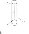
- FIG. 1 is an explanatory view of a living machine after weaving of a tubular woven fabric.
- FIG. 2 is an explanatory view of the base material after the cylindrical fabric is processed.
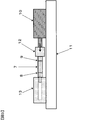
- FIG. 3 is a conceptual diagram of an apparatus for measuring the repulsive force of a tubular fabric.
- FIG. 4 is an explanatory diagram for drawing a marked line on the tubular fabric.
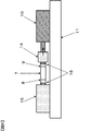
- FIG. 5 is a conceptual diagram of an apparatus for measuring a distance between marked lines during compression of a tubular fabric.
- FIG. 6 is a conceptual diagram of an apparatus for measuring a distance between marked lines when a tubular fabric is stretched.
- the tubular woven fabric according to the present invention is a cylindrical woven fabric having a double woven wall portion woven by crossing warps and wefts, wherein the outer weft and the inner weft do not cross each other. To do.
- polyester fibers the fiber which consists of a polyethylene terephthalate, a polybutylene terephthalate, a polypropylene terephthalate, those copolymers, etc. can be mentioned, for example.
- the elongation at break is 70% or less from the viewpoint of excellent strength and form stability. More preferably, it is 60% or less, more preferably 50% or less, and the lower limit is 10% or more.
- the total fineness of the fibers constituting the warp of the tubular woven fabric is preferably 560 dtex or less, more preferably 235 dtex or less, more preferably 100 dtex or less, and a lower limit of 10 dtex or more from the viewpoint of strength and form stability.
- the weaving density of the warp A when measured by cutting a tubular woven fabric is preferably 200 / inch (2.54 cm) or less, more preferably 180 / inch (2.54 cm) from the viewpoint of strength and form stability. ) Or less, more preferably 150 lines / inch (2.54 cm) or less, and the lower limit is 20 lines / inch (2.54 cm) or more.
- the total fineness of the fibers constituting the weft of the tubular woven fabric is preferably 560 dtex or less, more preferably 235 dtex or less, more preferably 100 dtex or less, and the lower limit is 10 dtex or more from the viewpoint of strength and form stability.
- the weave density of the inner layer side weft and the outer layer side weft when measured by cutting a tubular woven fabric is preferably 200 yarns / inch (2.54 cm) or less from the viewpoint of strength and form stability. Is 180 lines / inch (2.54 cm) or less, more preferably 150 lines / inch (2.54 cm) or less, and the lower limit is 20 lines / inch (2.54 cm) or more.
- the inner diameter of the tubular woven fabric is preferably 100 mm or less, more preferably 50 mm or less, more preferably 10 mm or less from the viewpoint of form stability.
- a preferable lower limit is about 1.5 mm from the viewpoint of weaving.
- the method for producing the tubular woven fabric of the present invention is not particularly limited as long as the tubular woven fabric defined in the present invention is obtained, but using a shuttle loom of two or more used arranged on the front side and the front side of the beam side, Weaving so that the wall has a double woven tubular shape, that is, a quadruple woven structure with a quadruple woven structure in which a connection point is not provided between the second and third layers and a hollow portion is formed. It is preferable that weaving is performed.
- a total of 2 shuttles for weft insertion of the wefts constituting the outer layer (hereinafter also referred to as outer layer wefts) and shuttles for inserting the wefts constituting the inner layers (hereinafter also referred to as inner layer wefts) 2 Use the shuttle of Ding. Each shuttle moves in and out on the rail.
- the shuttle on the front side of the weave is the inner layer of the cylindrical fabric
- the shuttle on the beam side is the outer layer.
- the weft supplied from the shuttle on the back side always passes over the shuttle on the front side of the weave, so that the inner layer weft intersects with the outer layer weft and is exposed on the surface.
- the weft insertion can be performed so that the inner layer weft and the outer layer weft do not cross each other by switching the positions of the front and rear shuttles when the inner layer weft is exposed.
- the tubular woven fabric of the present invention is measured at a location corresponding to the fabric width direction A of the tubular woven fabric (raw machine) 1 during weaving with the processed tubular woven fabric 2 as shown in FIG.
- the roundness c represented by the following formula of the outer diameter b in the direction perpendicular to the outer diameter a is preferably 0.8 or more and 1.2 or less, 0.85 or more, More preferably, it is 1.15 or less.
- the cylindrical fabric is a perfect circle or a shape close to a perfect circle, so that it is easy to sew a cylindrical thing of the same diameter.
- a woven fabric can be provided.
- the outer peripheral portion of the cross section of the wall portion constituting the tubular woven fabric has a homogeneous structure, the fiber material, fineness, woven density, By adjusting the outer diameter and inner diameter as appropriate, the roundness of the outer peripheral portion of the cross section can be improved.
- the repulsive force can be increased, for example, by using a fiber having higher rigidity as a fiber material, or by increasing the single yarn fineness, the total fineness, and the woven density.
- the repulsive force can be increased by constituting a fiber having a high single yarn fineness, such as a monofilament (preferably a diameter of 20 ⁇ m or more, more preferably 40 ⁇ m or more, and an upper limit of 150 ⁇ m or less), or at least
- a fiber having a high single yarn fineness such as a monofilament (preferably a diameter of 20 ⁇ m or more, more preferably 40 ⁇ m or more, and an upper limit of 150 ⁇ m or less), or at least
- the roundness can be increased by making the structure homogeneous and dense and improving the homogeneity of the outer peripheral portion of the cross section of the wall.
- the fiber having a small single yarn fineness is preferably a multifilament in which part or all of the single yarn diameter is 5 ⁇ m or less, more preferably 4 ⁇ m or less, and the lower limit is 1 ⁇ m or more.
- the single yarn diameter in the above range, the flexibility of the tubular woven fabric is improved, and a denser structure can be obtained.
- a method using a fiber having a high single yarn fineness for example, a monofilament (preferably a diameter of 20 ⁇ m or more and 40 ⁇ m or more is preferable, and an upper limit is 150 ⁇ m or less), or the outer or inner diameter of a cylindrical woven fabric. It is possible to further increase the repulsive force and increase the roundness by the method of reducing the size.
- the heat setting condition is preferably 60 ° C. or more higher than the glass transition temperature of the material used, more preferably 80 ° C. or more, preferably 20 ° C. or more lower than the melting point of the material used, more preferably 30 ° C. or more lower. preferable.
- the ratio of Fb that is, the rebound ratio Fc represented by the following formula is preferably 0.8 or more and 1.2 or less, and more preferably 0.85 or more and 1.15 or less.
- Rebound ratio Fc Fa / Fb
- the outer peripheral portion of the cross section of the wall portion constituting the tubular fabric has a homogeneous structure, a tubular fabric having a small repulsive anisotropy can be obtained. Furthermore, the repulsion ratio can be further reduced by appropriately adjusting the weave density, the outer diameter and the inner diameter of the tubular fabric so as to obtain an appropriate repulsive force. And by inserting a round bar having an outer diameter that matches the inner diameter of the woven tubular fabric into the hollow portion of the tubular fabric and performing heat setting, the tubular fabric contracts and the repulsive force increases. A tubular woven fabric having a resilience ratio in the above range can be easily obtained.
- a gauge line is drawn at a distance 5 times the maximum outer diameter of the fabric when measured without applying stress to the tubular fabric of the present invention, and a stress of 0.01 cN / dtex is applied in the warp direction of the tubular fabric.
- the relationship between the distance L1 between the marked lines when compressed in the above and the distance L2 between the marked lines when stretched with a stress of 0.01 cN / dtex in the warp direction is expressed by the following formula.
- the value of (L2 ⁇ L1) / L1 is preferably 0.15 or more, more preferably 0.18 or more, from the viewpoint that the stretchability and flexibility can be further improved.
- the upper limit is preferably 1.0.
- a tubular woven fabric excellent in stretchability, flexibility, and kink resistance (flexibility) can be provided. That is, when the tubular fabric is bent and bent, stress is applied in the compression direction on the bent inner peripheral side and simultaneously stress is applied in the extension direction on the outer peripheral side. On the other hand, since the outer periphery can be extended sufficiently, it means excellent kink resistance.
- the stretching operation or compressing operation with a stress of 0.01 cN / dtex usually corresponds to the stress when a person stretches and compresses the tubular fabric lightly in the warp direction by hand.
- the tubular fabric of the present invention has an elongation of 30% or less when stretched with a stress of 0.01 cN / dtex in the warp direction, and it is easy to feel a response when a person pulls it lightly by hand. This is preferable. More preferably, it is 20% or less, more preferably about 10%. Further, the lower limit is preferably 5% or more, more preferably 8% or more from the viewpoint that a feeling of elongation can be felt when a person pulls lightly by hand.
- the tubular woven fabric When it is in the above range, it is flexible and easy to operate even when a person sews by hand, and when transplanted as an artificial blood vessel, the tubular woven fabric has the same puncture property at any location in the outer circumferential direction of the tubular woven fabric.
- the tubular fabric does not have a bellows structure.
- the tubular fabric does not have a bellows structure.
- No bellows structure means that a core rod having a spiral or annular corrugated groove is inserted into a cylindrical fabric, and the fabric is not subjected to corrugated set processing by heating or is not pleated Say.
- the tubular fabric itself can be provided with stretchability even when a fiber having a low elongation, for example, a breaking elongation of 70% or less, is used as the fiber used for the tubular fabric, the tubular fabric itself can be provided with stretchability.
- a fiber having a low elongation for example, a breaking elongation of 70% or less
- Such a tubular fabric can be manufactured, for example, as follows.
- warp A warp A
- warp B warp B
- Such fibers are different from elastic yarns having so-called rubber elasticity and are generally recognized in the art as inelastic yarns.
- the warp A can be composed of various synthetic fibers such as nylon fiber and polyester fiber.
- polyester fibers of inelastic yarn are preferable from the viewpoint of strength and dimensional stability.
- inelastic yarn polyester fibers include fibers made of polyethylene terephthalate, polybutylene terephthalate, polypropylene terephthalate, and copolymers thereof.
- the warp A of the synthetic fiber exposed on the inner surface constituting the tubular woven fabric may be a directly spun ultrafine fiber or an ultrafine fiber obtained by removing sea-island composite fibers.
- a part or all of the single yarn diameter of the warp direction synthetic fiber exposed on the inner surface is preferably a multifilament of 5 ⁇ m or less.
- the warp B is preferably composed of dissolved yarn.
- the dissolved yarn is a fiber that is soluble in a solvent such as water or an alkaline solution.
- a solvent such as water or an alkaline solution.
- Specific examples of the dissolved yarn include water-soluble fibers such as polyvinyl alcohol fibers, isophthalic acid, and 5-sodium sulfoisophthalic acid.
- easy-soluble fibers such as polyester fibers and polylactic acid fibers in which a third component such as methoxypolyoxyethylene glycol is copolymerized can be used, but are not particularly limited.
- the temporary yarn removed after weaving can also be used as the warp B.
- the total fineness of each warp is preferably 560 dtex or less, more preferably 235 dtex or less, more preferably 100 dtex or less, and the lower limit is 10 dtex or more.
- the weave density of the warp A when measured by cutting the tubular woven fabric of the present invention is preferably 200 / inch (2.54 cm) or less, more preferably 180 / inch (2.54 cm) or less, more preferably Is 150 lines / inch (2.54 cm) or less, and the lower limit is 20 lines / inch (2.54 cm) or more.
- weft C and weft D are at least two types of wefts.
- a tubular woven fabric having a double structure is preferable.
- a preferred embodiment in this case is a case where the weft C is located in the inner layer of the tubular fabric and the weft D is located in the outer layer.
- the weft C located in the inner layer and the weft D located in the outer layer can be composed of various synthetic fibers such as nylon fiber and polyester fiber, but are preferably inelastic yarns. Of these, non-elastic polyester fibers are preferred in terms of strength and dimensional stability. Examples of inelastic yarn polyester fibers include fibers made of polyethylene terephthalate, polybutylene terephthalate, polypropylene terephthalate, and the like.
- the elongation at break is preferably 70% or less, more preferably 60% or less, more preferably 50% or less, and the lower limit is 10% or more.
- the weft C that is located in the inner layer and exposed on the inner surface can be an ultrafine fiber that has been spun from the sea-island composite fiber or directly spun using a sea-island composite fiber or a directly spun ultrafine fiber as a raw yarn.
- a part or all of the single yarn diameter of the synthetic fiber of these wefts C is preferably a multifilament of 5 ⁇ m or less, more preferably 4 ⁇ m or less, and the lower limit is 1 ⁇ m or more.
- the single yarn diameter of the weft D located in the outer layer is preferably a monofilament of 20 ⁇ m or more, more preferably 40 ⁇ m or more, and the upper limit is 150 ⁇ m or less.
- the total fineness of each weft is preferably 560 dtex or less, more preferably 235 dtex or less, more preferably 100 dtex or less, and the lower limit is 10 dtex or more.
- the weave density of each of the weft C and the weft D as measured by opening the post-processed tubular fabric is preferably 200 yarns / inch (2.54 cm) or less, more preferably 180 yarns / inch (2. 54 cm) or less, more preferably 150 lines / inch (2.54 cm) or less, and the lower limit is 20 lines / inch (2.54 cm) or more.
- the weft insertion method in which the inner layer weft and the outer layer weft do not cross each other is to use two or more shuttle looms arranged on the front side and the front side of the beam, and the inner layer weft is exposed.
- a method of exchanging the positions of the front and rear shuttles at the time of weft insertion can be mentioned.
- the warp B is woven at a high tension and the warp A is woven at a low tension within a range that does not hinder the opening.
- the tension of the warp B is preferably 0.5 to 1.5 cN / dtex
- the tension of the warp A is preferably 0.05 to 0.15 cN / dtex.
- the warp A and the warp B are preferably arranged at a ratio of 1 warp B to 2 to 10 warps A.
- the weft can be restrained by the warp A with the warp B as a fulcrum, and bumping can be suppressed. Therefore, the crimp rate of the warp A can be increased, and by removing the warp B after weaving, flexibility can be imparted to the tubular fabric.
- the warp B is preferably disposed between the weft C located in the inner layer and the weft D located in the outer layer.
- wefts C which are located in the inner layer of the tubular woven fabric, and wefts D located in the outer layer
- structural distortion occurs due to the difference in the circumferential length of the weft C and the weft D.
- extensibility can be provided to a cylindrical fabric.
- the weft C and the weft D do not intersect with each other, the structure of the outer peripheral portion of the cross section of the wall portion can be made uniform, and the tubular woven fabric when transplanted as an artificial blood vessel
- the puncture property is the same at any location in the outer circumferential direction, and the tubular fabric is excellent in form stability.
- the inner diameter of the tubular woven fabric is preferably 100 mm or less, more preferably 50 mm or less, more preferably 10 mm or less.
- a preferable lower limit is about 1.5 mm from the viewpoint of weaving.
- the post-processing step is preferably performed through the following steps, for example.
- the case where the internal diameter of a cylindrical textile fabric is 3.3 mm is illustrated.
- the raw thread oil agent is dropped and the warp B is contracted by hot water washing.
- the treatment conditions are preferably a temperature of 80 to 98 ° C. and a time of 15 to 40 minutes.
- Pre-heat set stabilizes the form of the warp A in which the crimp rate has increased as the warp B contracts.
- a round bar having an outer diameter of 3.0 mm is inserted into a cylindrical fabric, and both ends are fixed with a wire or the like, and heat treatment is performed.
- the outer diameter of the round bar to be used is appropriately selected according to the degree to which the woven tubular fabric is contracted by the pre-heat set.
- the treatment conditions are preferably a temperature of 160 to 190 ° C. and a time of 3 to 10 minutes.
- the material of the said round bar can mention SUS, for example.
- (C-1) Acid treatment The sea component of the sea-island composite fiber is embrittled by acid treatment.
- the acid include maleic acid.
- the treatment conditions are preferably a concentration of 0.1 to 1% by mass, a temperature of 100 to 150 ° C., and a time of 10 to 50 minutes. When sea-island composite fibers are not used, acid treatment can be omitted.
- (C-2) Alkali treatment The sea component of the sea-island composite fiber embrittled by the dissolved yarn and the acid treatment is eluted by alkali treatment.
- alkali include sodium hydroxide.
- the treatment conditions are preferably a concentration of 0.5 to 2% by mass, a temperature of 70 to 98 ° C., and a time of 60 to 100 minutes.
- (D) Heat set 1 (first time) The purpose is to maximize again the crimp of the warp that has been loosened by the sea removal treatment by the first heat setting.
- a round bar having an outer diameter of 3.3 mm is inserted into a cylindrical woven fabric, and heat treatment is performed by fixing both ends with a wire or the like while being compressed to the maximum in the warp direction so as not to cause wrinkles.
- the treatment conditions are preferably a temperature of 160 to 190 ° C. and a time of 3 to 10 minutes.
- the material of the said round bar can mention SUS, for example.
- the second heat set is intended to make a woven fabric having a shrinkage allowance while leaving the bending point of the crimp, but the second time may or may not be performed.
- a round bar having an outer diameter of 3.3 mm is inserted into a cylindrical woven fabric, and heat treatment is performed by fixing both ends with a wire or the like while extending 20 to 50% in the warp direction.
- the treatment conditions are a temperature lower by 10 to 20 ° C. than the first heat setting, and a time of 3 to 10 minutes is preferable. Examples of the round bar include SUS.
- the thus obtained tubular woven fabric has a uniform structure at the outer peripheral portion of the cross section of the wall and is excellent in form stability.
- the cross-sectional shape cut in the radial direction is almost a perfect circle, the inner surface has small irregularities, and is excellent in stretchability, flexibility, kink resistance (flexibility), shape retention, and repulsive force. It can be used for fluids, powder transfer and hose for protecting linear objects such as wires, cables and conduits, medical substrates such as cylindrical filters and artificial blood vessels, etc. In particular, it can be suitably used as an artificial blood vessel.
- Cut at 50 mm intervals in the warp direction measured at five locations, and evaluated by average value.
- FIG. 3 is a conceptual diagram of an apparatus for measuring the repulsive force of a cylindrical fabric.
- the mounting gauge head 3 of the compression stage 4,5Cm second sample holding ring stand 10 cm 2 the tubular fabric 2 after processing a sample Is placed on the compression table 4, the probe is brought into contact with the upper part of the sample so that the shape of the cylindrical fabric does not deform, and zero-pasted, and then compressed in the direction of arrow 5 so that the distance is 1 ⁇ 2 of the sample diameter.
- the repulsive force 6 was measured.
- FIG. 4 is an explanatory diagram for drawing a marked line on the tubular fabric.
- the first marked line 8 is placed on the outer periphery of the fabric 5 mm from one end of the tubular fabric 7.
- a second benchmark 9 is drawn on the outer periphery of the fabric at a distance X that is five times the maximum value of the outer diameter of the fabric from the first benchmark.
- the tubular fabric 7 is cut in the radial direction at a position 5 mm from the second marked line.
- FIG. 5 is a conceptual diagram of an apparatus for measuring the distance between the marked lines during compression of the cylindrical fabric, but as shown in FIG. 5, the apparatus is a load measuring instrument (force gauge) 10.
- a HANDY DIGITAL FORCE GAUGE HF-1 (rated capacity 10N) manufactured by Nippon Measuring System Co., Ltd. is installed on the gantry 11 and a compression chuck jig 12 having a core bar part is attached to the load measuring instrument 10.
- a compression receiving jig 13 having an insertable hole is attached to the gantry 11.
- the distance L1 between the marked lines when the cylindrical fabric 7 is set in the above apparatus through the core rod portion of the compression chuck jig 12 and compressed with a stress of 0.01 cN / dtex in the warp direction (between the marked lines during compression) Distance) was measured with calipers.
- FIG. 6 is a conceptual diagram of an apparatus for measuring the distance between the marked lines when the tubular fabric is stretched. As shown in FIG. 6, the apparatus is used as a load measuring device (force gauge) 10.
- HANDY DIGITAL FORCE GAUGE HF-1 (rated capacity 10N) manufactured by Nippon Measurement System Co., Ltd. is installed on the gantry 11, the extension chuck jig 14 is attached to the load measuring instrument 10, and the extension receiving jig 15 is installed on the gantry 11. It is attached to.
- the outer side of the marked line of the tubular woven fabric 7 was fixed with a fixing string 16 and the distance L2 between the marked lines when stretched with a stress of 0.01 cN / dtex in the warp direction (distance between the marked lines when stretched) was measured with a caliper. .
- the stress was calculated by the following formula.
- Warp A polyethylene terephthalate fiber
- 66 dtex 9 filaments (after sea removal treatment: 52.8 dtex, 630 filaments)
- Warp B dissolved yarn
- the weave density measured by cutting open the tubular fabric after post-processing with the warp B tension of 0.9 cN / dtex and the warp A tension of 0.1 cN / dtex is warp A, 136 / inch (2. 54 cm), weft C, 120 yarns / inch (2.54 cm), weft D, 120 yarns / inch (2.54 cm), and a tubular woven fabric having an inner diameter of 3.3 mm was woven.
- the warp A and the warp B were arranged at a ratio of one warp B to three warps A. Further, the warp B was arranged between the weft C located in the inner layer and the weft D located in the outer layer.
- (C-1) Acid treatment Maleic acid was used as the acid.
- the treatment conditions were a concentration of 0.2% by mass, a temperature of 130 ° C., and a time of 30 minutes.
- the treatment conditions were a concentration of 1.0% by mass, a temperature of 80 ° C., and a time of 90 minutes.
- Table 1 shows the characteristics of the obtained tubular woven fabric.
- the operability was good, and the stretchability, flexibility, resilience, and shape retention were excellent. In addition, it did not have a bellows structure. Further, there is no exposure of the weft C on the outer surface of the tubular fabric, and when sewing the tubular fabrics together, the puncture property is the same at any location in the circumferential direction of the tubular fabric, and the radial fabric was cut in the radial direction. Since the cross section was almost a perfect circle, it was much easier to sew compared to the tubular fabric obtained in Comparative Example 1 described later.
- Example 2 In Example 1, the cylindrical woven fabric was obtained in the same manner as in Example 1 except that the inner diameter of the cylindrical woven fabric was 4.0 mm and the second heat setting was not performed.
- Example 3 In Example 1, a cylindrical woven fabric was obtained in the same manner as in Example 1 except that the inner diameter of the cylindrical woven fabric was 5.0 mm and the second heat setting was extended by 20%.
- Example 4 In Example 1, weaving density measured by cutting open a tubular fabric after post-processing using warp A instead of warp B (dissolved yarn) of tubular fabric and setting all warp tensions to 0.5 cN / dtex. Becomes a warp A, 130 yarns / inch (2.54 cm), weft C, 90 yarns / inch (2.54 cm), weft D, 90 yarns / inch (2.54 cm), and a tubular fabric with an inner diameter of 3.3 mm A tubular woven fabric was obtained in the same manner as in Example 1 except that the second heat setting was not performed.
- the obtained tubular woven fabric was excellent in resilience and form retention. Further, there is no exposure of the weft C on the outer surface of the tubular fabric, and when sewing the tubular fabrics together, the puncture property is the same at any location in the circumferential direction of the tubular fabric, and the radial fabric was cut in the radial direction. Since the cross section was almost a perfect circle, it was easier to sew compared to the tubular fabric obtained in Comparative Example 3 described later.
- Example 1 A tubular woven fabric was obtained in the same manner as in Example 1 except that weaving was performed without changing the positions of the weft C as a shuttle on the front side and the weft D as a beam side shuttle during weaving.
- the obtained tubular fabric was inferior in roundness because the portion where the wefts crossed out even after inserting a round bar and heat-setting, protruded from the outer shape. Further, in terms of physical properties, the portion where the wefts intersected was poorly bent, and the balance of resilience in the perpendicular direction was poor. Further, when the tubular fabrics were stitched together, the portion where the wefts intersected was hard and difficult to stitch.
- Example 2 weaving is performed without changing the position of the weft C as the shuttle on the front side and the weft D as the beam side shuttle during weaving, and the weft C and the weft D are the same thread type polyethylene terephthalate fiber, 66 dtex, A tubular woven fabric was obtained in the same manner as in Example 2 except that weaving was performed using 9 filaments (after sea removal treatment: 52.8 dtex, 630 filaments).
- the obtained tubular woven fabric protruded at the portion where the wefts intersected in the same manner as in Comparative Example 1, the portion was poorly bent, and the balance of resilience in the perpendicular direction was bad. Further, when the tubular fabrics were stitched together, the portion where the wefts intersected was hard and difficult to stitch.
- Example 3 A tubular woven fabric was obtained in the same manner as in Example 4 except that weaving was performed without changing the positions of the weft C as the shuttle on the front side and the weft D as the beam side shuttle during weaving.
- tubular woven fabric according to the present invention can be suitably used for artificial blood vessels, but the application range is not limited thereto.
Landscapes
- Engineering & Computer Science (AREA)
- Textile Engineering (AREA)
- Woven Fabrics (AREA)
- Prostheses (AREA)
Abstract
Priority Applications (3)
| Application Number | Priority Date | Filing Date | Title |
|---|---|---|---|
| EP19793795.6A EP3786325A4 (fr) | 2018-04-26 | 2019-04-12 | Tissu tubulaire et matériau de base à usage médical mettant en oeuvre un tel tissu tubulaire |
| JP2019524300A JPWO2019208262A1 (ja) | 2018-04-26 | 2019-04-12 | 筒状織物およびこれを用いた医療用基材 |
| US17/049,144 US11299826B2 (en) | 2018-04-26 | 2019-04-12 | Tubular fabric and base material for medical use using same |
Applications Claiming Priority (2)
| Application Number | Priority Date | Filing Date | Title |
|---|---|---|---|
| JP2018085164 | 2018-04-26 | ||
| JP2018-085164 | 2018-04-26 |
Publications (1)
| Publication Number | Publication Date |
|---|---|
| WO2019208262A1 true WO2019208262A1 (fr) | 2019-10-31 |
Family
ID=68295431
Family Applications (1)
| Application Number | Title | Priority Date | Filing Date |
|---|---|---|---|
| PCT/JP2019/015929 Ceased WO2019208262A1 (fr) | 2018-04-26 | 2019-04-12 | Tissu tubulaire et matériau de base à usage médical mettant en œuvre un tel tissu tubulaire |
Country Status (5)
| Country | Link |
|---|---|
| US (1) | US11299826B2 (fr) |
| EP (1) | EP3786325A4 (fr) |
| JP (1) | JPWO2019208262A1 (fr) |
| TW (1) | TW201945039A (fr) |
| WO (1) | WO2019208262A1 (fr) |
Cited By (5)
| Publication number | Priority date | Publication date | Assignee | Title |
|---|---|---|---|---|
| WO2021182060A1 (fr) * | 2020-03-09 | 2021-09-16 | 東レ株式会社 | Tissu médical, procédé de production de celui-ci, organe artificiel et endoprothèse couverte |
| CN113952075A (zh) * | 2020-10-28 | 2022-01-21 | 清华大学 | 一种多尺度复合结构仿生小口径人工血管及其制备方法 |
| WO2022040778A1 (fr) | 2020-08-27 | 2022-03-03 | Sanexen Environmental Services Inc. | Doublure tissée tubulaire |
| JPWO2022209633A1 (fr) * | 2021-03-30 | 2022-10-06 | ||
| CN117966330A (zh) * | 2024-03-07 | 2024-05-03 | 东莞特大纺织科技有限公司 | 双层宽窄手把带及其编织方法、编织设备 |
Families Citing this family (1)
| Publication number | Priority date | Publication date | Assignee | Title |
|---|---|---|---|---|
| US20260071357A1 (en) * | 2024-09-09 | 2026-03-12 | North Carolina State University | Multilayer weaving for seamless apparel production |
Citations (8)
| Publication number | Priority date | Publication date | Assignee | Title |
|---|---|---|---|---|
| JPS63196889U (fr) * | 1987-06-09 | 1988-12-19 | ||
| JPH055242A (ja) * | 1990-10-18 | 1993-01-14 | Nippon Oil Co Ltd | 筒状多層織物とその製造方法 |
| JPH06184857A (ja) | 1992-10-12 | 1994-07-05 | Kikuchi Uebu Tec:Kk | 厚地ベルト及びその製造装置 |
| JPH0880342A (ja) | 1994-09-13 | 1996-03-26 | Seiren Co Ltd | 人工血管用管状体 |
| JP2779456B2 (ja) | 1990-08-28 | 1998-07-23 | ミードックス・メディカルス・インコーポレイテッド | 自己保持型編織製人工血管およびその製造法 |
| JP2005261867A (ja) * | 2004-02-18 | 2005-09-29 | Ube Ind Ltd | 管状の人工器官 |
| JP2009270236A (ja) * | 2008-05-12 | 2009-11-19 | Ashimori Ind Co Ltd | 二重筒状織物 |
| WO2018066476A1 (fr) | 2016-10-07 | 2018-04-12 | 東レ株式会社 | Tissu tubulaire |
Family Cites Families (26)
| Publication number | Priority date | Publication date | Assignee | Title |
|---|---|---|---|---|
| GB191010540A (en) | 1910-04-29 | 1911-04-27 | Arthur Henry Walker | Improvements in Rotary Offset Printing Presses. |
| GB191224140A (en) * | 1912-03-19 | 1913-06-19 | Albert Henry Henderson | Improvements in and relating to Fabric or Cloth. |
| US3350488A (en) * | 1958-05-27 | 1967-10-31 | Du Pont | Process for the production of sharp-edge fibers |
| US3531368A (en) * | 1966-01-07 | 1970-09-29 | Toray Industries | Synthetic filaments and the like |
| JPS5711650A (en) | 1980-06-23 | 1982-01-21 | Mitsubishi Rayon Co | Manufacture of artificial blood vessel |
| DE3230858C2 (de) * | 1982-08-19 | 1985-01-24 | Ahmadi, Ali, Dr. med., 7809 Denzlingen | Ringprothese |
| JPS59225920A (ja) * | 1983-06-07 | 1984-12-19 | Tokyo Gas Co Ltd | 管路の内張り材 |
| JPH055355Y2 (fr) * | 1988-01-27 | 1993-02-12 | ||
| US5273080A (en) | 1990-10-18 | 1993-12-28 | Nippon Oil Co., Ltd. | Tubular multilayer woven fabric and method for weaving same |
| JP2749447B2 (ja) * | 1991-03-25 | 1998-05-13 | ミードックス メディカルズ インコーポレイテッド | 人工血管 |
| DE4335621A1 (de) * | 1993-10-19 | 1995-04-27 | Rotecno Ag | Saugfähiges Gewebematerial aus synthetischer Endlosfaser |
| US6881194B2 (en) * | 2001-03-21 | 2005-04-19 | Asahi Intec Co., Ltd. | Wire-stranded medical hollow tube, and a medical guide wire |
| JP2008505713A (ja) * | 2004-07-07 | 2008-02-28 | クック・インコーポレイテッド | グラフト、ステントグラフト、および製造方法 |
| US20060009839A1 (en) * | 2004-07-12 | 2006-01-12 | Scimed Life Systems, Inc. | Composite vascular graft including bioactive agent coating and biodegradable sheath |
| CA2697230C (fr) * | 2007-11-05 | 2012-04-10 | Ibco Srl | Materiau en feuille a surface anti-glissante constitue de bandes et de monofilaments |
| US9260805B2 (en) * | 2010-04-28 | 2016-02-16 | Toray Industries, Inc. | Base fabric for stent graft, and stent graft |
| EP2605908B1 (fr) * | 2010-08-17 | 2020-11-11 | Low & Bonar Gmbh | Matériau composite comportant un matériau de revêtement |
| JP5620761B2 (ja) * | 2010-09-07 | 2014-11-05 | 東洋紡Stc株式会社 | 高密度織物 |
| AU2011265360B2 (en) * | 2010-12-30 | 2014-03-06 | Cook Medical Technologies Llc | Composite woven fabric for endoluminal devices |
| JP6323332B2 (ja) * | 2013-04-26 | 2018-05-16 | 東レ株式会社 | 人工血管 |
| US9968435B2 (en) * | 2013-07-10 | 2018-05-15 | Terumo Kabushiki Kaisha | Body lumen graft base, production method of body lumen graft base, and body lumen graft using the same |
| CA2929523A1 (fr) * | 2013-11-29 | 2015-06-04 | Toray Industries, Inc. | Prothese vasculaire |
| US20150203995A1 (en) * | 2014-01-22 | 2015-07-23 | International Textile Group, Inc. | Antistatic Fabric Containing Polyetherimide Filaments |
| CA3014768C (fr) * | 2016-03-04 | 2021-04-06 | Bauer Hockey Ltd. | Materiau de tissage 3d et procede de tissage 3d destines a du materiel sportif |
| CN106012240B (zh) * | 2016-07-18 | 2018-10-02 | 水力消防科技有限公司 | 一种消防水带双层带坯及其制作方法 |
| US10751507B2 (en) * | 2017-04-10 | 2020-08-25 | Syn Variflex, Llc | Thermally controlled variable-flexibility catheters and methods of manufacturing same |
-
2019
- 2019-04-12 JP JP2019524300A patent/JPWO2019208262A1/ja active Pending
- 2019-04-12 WO PCT/JP2019/015929 patent/WO2019208262A1/fr not_active Ceased
- 2019-04-12 EP EP19793795.6A patent/EP3786325A4/fr not_active Withdrawn
- 2019-04-12 US US17/049,144 patent/US11299826B2/en not_active Expired - Fee Related
- 2019-04-17 TW TW108113347A patent/TW201945039A/zh unknown
Patent Citations (8)
| Publication number | Priority date | Publication date | Assignee | Title |
|---|---|---|---|---|
| JPS63196889U (fr) * | 1987-06-09 | 1988-12-19 | ||
| JP2779456B2 (ja) | 1990-08-28 | 1998-07-23 | ミードックス・メディカルス・インコーポレイテッド | 自己保持型編織製人工血管およびその製造法 |
| JPH055242A (ja) * | 1990-10-18 | 1993-01-14 | Nippon Oil Co Ltd | 筒状多層織物とその製造方法 |
| JPH06184857A (ja) | 1992-10-12 | 1994-07-05 | Kikuchi Uebu Tec:Kk | 厚地ベルト及びその製造装置 |
| JPH0880342A (ja) | 1994-09-13 | 1996-03-26 | Seiren Co Ltd | 人工血管用管状体 |
| JP2005261867A (ja) * | 2004-02-18 | 2005-09-29 | Ube Ind Ltd | 管状の人工器官 |
| JP2009270236A (ja) * | 2008-05-12 | 2009-11-19 | Ashimori Ind Co Ltd | 二重筒状織物 |
| WO2018066476A1 (fr) | 2016-10-07 | 2018-04-12 | 東レ株式会社 | Tissu tubulaire |
Cited By (8)
| Publication number | Priority date | Publication date | Assignee | Title |
|---|---|---|---|---|
| WO2021182060A1 (fr) * | 2020-03-09 | 2021-09-16 | 東レ株式会社 | Tissu médical, procédé de production de celui-ci, organe artificiel et endoprothèse couverte |
| WO2022040778A1 (fr) | 2020-08-27 | 2022-03-03 | Sanexen Environmental Services Inc. | Doublure tissée tubulaire |
| EP4204615A4 (fr) * | 2020-08-27 | 2024-08-28 | Sanexen Environmental Services Inc. | Doublure tissée tubulaire |
| CN113952075A (zh) * | 2020-10-28 | 2022-01-21 | 清华大学 | 一种多尺度复合结构仿生小口径人工血管及其制备方法 |
| CN113952075B (zh) * | 2020-10-28 | 2024-06-11 | 清华大学 | 一种多尺度复合结构仿生小口径人工血管及其制备方法 |
| JPWO2022209633A1 (fr) * | 2021-03-30 | 2022-10-06 | ||
| WO2022209633A1 (fr) * | 2021-03-30 | 2022-10-06 | テルモ株式会社 | Vaisseau sanguin artificiel |
| CN117966330A (zh) * | 2024-03-07 | 2024-05-03 | 东莞特大纺织科技有限公司 | 双层宽窄手把带及其编织方法、编织设备 |
Also Published As
| Publication number | Publication date |
|---|---|
| JPWO2019208262A1 (ja) | 2021-03-18 |
| TW201945039A (zh) | 2019-12-01 |
| US20210238774A1 (en) | 2021-08-05 |
| EP3786325A1 (fr) | 2021-03-03 |
| EP3786325A4 (fr) | 2022-01-19 |
| US11299826B2 (en) | 2022-04-12 |
Similar Documents
| Publication | Publication Date | Title |
|---|---|---|
| JPWO2019208262A1 (ja) | 筒状織物およびこれを用いた医療用基材 | |
| CN108472122B (zh) | 医疗用布帛 | |
| JP5750545B2 (ja) | 極細ポリエステル繊維及び筒状シームレス織物 | |
| CN111417362A (zh) | 医疗用的织物 | |
| CN111295154A (zh) | 医疗用织物 | |
| JP7131392B2 (ja) | 織物及びその製造方法 | |
| JP6091618B2 (ja) | 生体管腔グラフト基材および生体管腔グラフト基材の製造方法ならびに当該生体管腔グラフト基材を用いてなる生体管腔グラフト | |
| JP6438692B2 (ja) | 医療用布帛 | |
| JP2008202204A (ja) | 極細繊維布帛の製造方法 | |
| JP5729111B2 (ja) | ステントグラフト用基布およびステントグラフト | |
| JP2011245282A (ja) | ステントグラフト用基布およびステントグラフト | |
| JP5216970B2 (ja) | ポリエステル編地およびその製造方法および繊維製品 | |
| JP2009256865A (ja) | 極細繊維布帛とその製造方法 | |
| WO2016159264A1 (fr) | Greffon endoprothétique | |
| JP2004115976A (ja) | 異形血管補綴材用袋織り管状体の製造方法 | |
| JP2804784B2 (ja) | 通気性防水布の製造方法 | |
| WO2021182060A1 (fr) | Tissu médical, procédé de production de celui-ci, organe artificiel et endoprothèse couverte | |
| US20170035225A1 (en) | Quilt cover | |
| Hoffman | Fabrication and Testing of Polyester | |
| JPWO2019138900A1 (ja) | 緯糸多重織物及びその製造方法 | |
| JPH0528143B2 (fr) |
Legal Events
| Date | Code | Title | Description |
|---|---|---|---|
| ENP | Entry into the national phase |
Ref document number: 2019524300 Country of ref document: JP Kind code of ref document: A |
|
| 121 | Ep: the epo has been informed by wipo that ep was designated in this application |
Ref document number: 19793795 Country of ref document: EP Kind code of ref document: A1 |
|
| NENP | Non-entry into the national phase |
Ref country code: DE |
|
| WWE | Wipo information: entry into national phase |
Ref document number: 2019793795 Country of ref document: EP |
|
| ENP | Entry into the national phase |
Ref document number: 2019793795 Country of ref document: EP Effective date: 20201126 |