WO2019208273A1 - タブ、缶蓋及び缶蓋の製造方法 - Google Patents
タブ、缶蓋及び缶蓋の製造方法 Download PDFInfo
- Publication number
- WO2019208273A1 WO2019208273A1 PCT/JP2019/016014 JP2019016014W WO2019208273A1 WO 2019208273 A1 WO2019208273 A1 WO 2019208273A1 JP 2019016014 W JP2019016014 W JP 2019016014W WO 2019208273 A1 WO2019208273 A1 WO 2019208273A1
- Authority
- WO
- WIPO (PCT)
- Prior art keywords
- tab
- lid
- rivet
- layer
- pressing
- Prior art date
- Legal status (The legal status is an assumption and is not a legal conclusion. Google has not performed a legal analysis and makes no representation as to the accuracy of the status listed.)
- Ceased
Links
Images


Classifications
-
- B—PERFORMING OPERATIONS; TRANSPORTING
- B21—MECHANICAL METAL-WORKING WITHOUT ESSENTIALLY REMOVING MATERIAL; PUNCHING METAL
- B21D—WORKING OR PROCESSING OF SHEET METAL OR METAL TUBES, RODS OR PROFILES WITHOUT ESSENTIALLY REMOVING MATERIAL; PUNCHING METAL
- B21D51/00—Making hollow objects
- B21D51/16—Making hollow objects characterised by the use of the objects
- B21D51/38—Making inlet or outlet arrangements of cans, tins, baths, bottles, or other vessels; Making can ends; Making closures
- B21D51/383—Making inlet or outlet arrangements of cans, tins, baths, bottles, or other vessels; Making can ends; Making closures scoring lines, tear strips or pulling tabs
-
- B—PERFORMING OPERATIONS; TRANSPORTING
- B21—MECHANICAL METAL-WORKING WITHOUT ESSENTIALLY REMOVING MATERIAL; PUNCHING METAL
- B21D—WORKING OR PROCESSING OF SHEET METAL OR METAL TUBES, RODS OR PROFILES WITHOUT ESSENTIALLY REMOVING MATERIAL; PUNCHING METAL
- B21D51/00—Making hollow objects
- B21D51/16—Making hollow objects characterised by the use of the objects
- B21D51/38—Making inlet or outlet arrangements of cans, tins, baths, bottles, or other vessels; Making can ends; Making closures
- B21D51/44—Making closures, e.g. caps
-
- B—PERFORMING OPERATIONS; TRANSPORTING
- B41—PRINTING; LINING MACHINES; TYPEWRITERS; STAMPS
- B41M—PRINTING, DUPLICATING, MARKING, OR COPYING PROCESSES; COLOUR PRINTING
- B41M1/00—Inking and printing with a printer's forme
- B41M1/10—Intaglio printing ; Gravure printing
-
- B—PERFORMING OPERATIONS; TRANSPORTING
- B41—PRINTING; LINING MACHINES; TYPEWRITERS; STAMPS
- B41M—PRINTING, DUPLICATING, MARKING, OR COPYING PROCESSES; COLOUR PRINTING
- B41M1/00—Inking and printing with a printer's forme
- B41M1/26—Printing on other surfaces than ordinary paper
- B41M1/28—Printing on other surfaces than ordinary paper on metals
-
- B—PERFORMING OPERATIONS; TRANSPORTING
- B65—CONVEYING; PACKING; STORING; HANDLING THIN OR FILAMENTARY MATERIAL
- B65D—CONTAINERS FOR STORAGE OR TRANSPORT OF ARTICLES OR MATERIALS, e.g. BAGS, BARRELS, BOTTLES, BOXES, CANS, CARTONS, CRATES, DRUMS, JARS, TANKS, HOPPERS, FORWARDING CONTAINERS; ACCESSORIES, CLOSURES, OR FITTINGS THEREFOR; PACKAGING ELEMENTS; PACKAGES
- B65D17/00—Rigid or semi-rigid containers specially constructed to be opened by cutting or piercing, or by tearing of frangible members or portions
- B65D17/28—Rigid or semi-rigid containers specially constructed to be opened by cutting or piercing, or by tearing of frangible members or portions at lines or points of weakness
- B65D17/401—Rigid or semi-rigid containers specially constructed to be opened by cutting or piercing, or by tearing of frangible members or portions at lines or points of weakness characterised by having the line of weakness provided in an end wall
- B65D17/4012—Rigid or semi-rigid containers specially constructed to be opened by cutting or piercing, or by tearing of frangible members or portions at lines or points of weakness characterised by having the line of weakness provided in an end wall for opening partially by means of a tearing tab
-
- B—PERFORMING OPERATIONS; TRANSPORTING
- B65—CONVEYING; PACKING; STORING; HANDLING THIN OR FILAMENTARY MATERIAL
- B65D—CONTAINERS FOR STORAGE OR TRANSPORT OF ARTICLES OR MATERIALS, e.g. BAGS, BARRELS, BOTTLES, BOXES, CANS, CARTONS, CRATES, DRUMS, JARS, TANKS, HOPPERS, FORWARDING CONTAINERS; ACCESSORIES, CLOSURES, OR FITTINGS THEREFOR; PACKAGING ELEMENTS; PACKAGES
- B65D2517/00—Containers specially constructed to be opened by cutting, piercing or tearing of wall portions, e.g. preserving cans or tins
- B65D2517/0001—Details
- B65D2517/001—Action for opening container
- B65D2517/0014—Action for opening container pivot tab and push-down tear panel
-
- B—PERFORMING OPERATIONS; TRANSPORTING
- B65—CONVEYING; PACKING; STORING; HANDLING THIN OR FILAMENTARY MATERIAL
- B65D—CONTAINERS FOR STORAGE OR TRANSPORT OF ARTICLES OR MATERIALS, e.g. BAGS, BARRELS, BOTTLES, BOXES, CANS, CARTONS, CRATES, DRUMS, JARS, TANKS, HOPPERS, FORWARDING CONTAINERS; ACCESSORIES, CLOSURES, OR FITTINGS THEREFOR; PACKAGING ELEMENTS; PACKAGES
- B65D2517/00—Containers specially constructed to be opened by cutting, piercing or tearing of wall portions, e.g. preserving cans or tins
- B65D2517/0001—Details
- B65D2517/001—Action for opening container
- B65D2517/0016—Action for opening container pivot tab, push-down and pull-out tear panel
-
- B—PERFORMING OPERATIONS; TRANSPORTING
- B65—CONVEYING; PACKING; STORING; HANDLING THIN OR FILAMENTARY MATERIAL
- B65D—CONTAINERS FOR STORAGE OR TRANSPORT OF ARTICLES OR MATERIALS, e.g. BAGS, BARRELS, BOTTLES, BOXES, CANS, CARTONS, CRATES, DRUMS, JARS, TANKS, HOPPERS, FORWARDING CONTAINERS; ACCESSORIES, CLOSURES, OR FITTINGS THEREFOR; PACKAGING ELEMENTS; PACKAGES
- B65D2517/00—Containers specially constructed to be opened by cutting, piercing or tearing of wall portions, e.g. preserving cans or tins
- B65D2517/50—Non-integral frangible members applied to, or inserted in, a preformed opening
- B65D2517/5072—Details of hand grip, tear- or lift-tab
- B65D2517/5075—Hand grip with finger opening
Definitions
- the present invention relates to a tab used in a can container, a can lid, and a method for manufacturing the can lid.
- a steion tab type can lid that is opened by a tab is used.
- Such a can lid lifts the finger hook part of the tab fixed to the panel part by a rivet, thereby generating an insulator action, breaking a part of the panel part along the score line, and opening the panel part. It is the structure to do.
- a cylindrical rivet formed in the panel portion is inserted into a rivet hole formed in the tab, and the upper end portion of the rivet is caulked to fix the tab to the panel portion. For this reason, the tab is fixed to the panel portion so as to be rotatable in the circumferential direction around the rivet.
- an object of the present invention is to provide a tab, a can lid, and a method for manufacturing the can lid that can prevent rotation in the circumferential direction with a simple configuration.
- the tab is formed integrally with the fixing portion including the rivet hole into which the rivet formed in the panel portion of the can lid is inserted, and is formed in the panel portion.
- the can lid includes a rivet and a panel portion including a score line that is provided adjacent to the rivet and breaks when an external force is applied to form an opening piece;
- a fixing part including a rivet hole into which a rivet is inserted, a pressing part configured to be integrated with the fixing part, pressing a score line region formed in the panel part, and a pressing part configured integrally with the pressing part
- a tab formed of a metal plate having a finger hook portion and a resin film laminated on at least one main surface of a base material formed of a metal material.
- a method for producing a can lid includes forming a metal plate by adhering a film layer to at least one main surface of a thin plate-like substrate formed of a metal material, and forming a panel for the can lid.
- a fixing part including a rivet hole into which a rivet formed in the part is inserted, a pressing part configured integrally with the fixing part and pressing in a region of a score line formed in the panel part, and the pressing part;
- the metal plate is provided with a tab having a finger hook portion integrally formed so that a main surface provided with the film layer of the metal plate becomes an outer main surface when the tab is attached to the panel portion.
- the molded tab is placed on the panel portion, and the rivet inserted into the rivet hole is caulked.
- the present invention it is possible to provide a tab, a can lid, and a method for manufacturing the can lid that can prevent rotation in the circumferential direction with a simple configuration.
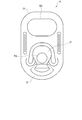
- FIG. 1 is a plan view showing a configuration of a can lid according to an embodiment of the present invention.
- FIG. 2 is a cross-sectional view showing the configuration of the can lid.
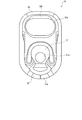
- FIG. 3 is a plan view showing a configuration of a tab used in the can lid.
- FIG. 4 is a plan view showing the configuration of the tab.
- FIG. 5 is a cross-sectional view showing a partial configuration of the tab.
- FIG. 6 is an explanatory view showing an example of a method for manufacturing the can lid.
- FIG. 7 is an explanatory view showing an example of a method for manufacturing the can lid.
- FIG. 8 is an explanatory view showing an example of a method for manufacturing the can lid.
- FIG. 9 is a flowchart showing an example of a method for manufacturing the can lid.
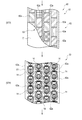
- FIG. 10 is a plan view showing a modification of the print layer of the tab.
- FIG. 11 is a plan view showing a modification of the print layer of the tab.
- FIG. 12 is a cross-sectional view showing a modified example of a partial configuration of the tab.
- FIG. 13 is a cross-sectional view showing a modification of a partial configuration of the tab.
- FIG. 14 is a cross-sectional view showing a modified example of a partial configuration of the tab.
- FIG. 1 is a plan view showing the configuration of a can lid 1 according to an embodiment of the present invention
- FIG. 2 is a cross-sectional view showing the configuration of the can lid 1.
- 3 and 4 are plan views showing the configuration of the tab 14, where FIG. 3 is shown from the front side of the can lid 1 and FIG. 4 is shown from the panel portion 11 side of the can lid 1.
- FIG. 5 is a cross-sectional view showing a part of the tab 14, that is, the configuration of the material constituting the tab 14.
- 6 to 8 are explanatory views showing an example of each process of the manufacturing method of the can lid 1
- FIG. 9 is a flowchart showing an example of each process of the manufacturing method of the can lid 1.
- the can lid 1 is a so-called Steion Tab (SOT) type.
- SOT Steion Tab
- the can lid 1 is a member that constitutes an opening for discharging the contents from the can container to the outside of the can container in which beverages such as carbonated drinks and alcoholic drinks are stored as the contents.
- the can lid 1 is assembled integrally with the can body of the can container by a tightening process.
- the can container may be either a positive pressure can having a positive pressure inside, or a negative pressure can having a negative pressure inside, and may be a two-piece can or a three-piece can.
- the contents are not limited to beverages, and may be foods or food / beverage products. That is, various contents enclosed in a can can be applied.
- the can lid 1 includes a panel portion 11, an annular groove portion 12 provided on the outer peripheral edge of the panel portion 11, and a flange portion 13 provided on the outer peripheral edge of the annular groove portion 12. And a tab 14 that is provided on the panel portion 11 and has a finger hooking portion 33 for hooking a user's finger.
- the can lid 1 is formed by pressing a metal plate so that the panel portion 11, the groove portion 12 and the flange portion 13 are integrally formed, and then a tab 14 formed in a separate process is fixed to the panel portion 11. Is done.
- the panel unit 11 is formed in a disc shape.
- the panel unit 11 includes a rivet 21 and a score line 22 provided adjacent to the rivet 21.
- the panel portion 11 has a recess provided between the score line 22 and the finger hooking portion 33 of the tab 14 with the rivet 21 interposed therebetween, or a dome-like protrusion provided at a portion in contact with the tab 14. Part or the like as appropriate.
- the rivet 21 is provided on one main surface of the panel portion 11, in other words, on the main surface of the panel portion 11 located on the outer surface side when provided on the can body of the can container.
- the rivet 21 is formed in a columnar shape that protrudes from one main surface of the panel portion 11 at substantially the center of the panel portion 11.
- the rivet 21 is formed by drawing the center of the panel portion 11 into a cylindrical shape.
- the rivet 21 is configured so that the tab 14 can be fixed to the panel portion 11 by caulking after the tab 14 is arranged.
- an opening piece 27 for forming the opening portion of the can lid 1 in the panel portion 11 is formed in the panel portion 11.
- the score line 22 is provided in a substantially elliptical shape, for example, from the vicinity of the rivet 21 to the vicinity of the outer peripheral edge of the panel portion 11.
- Such a score line 22 constitutes a fragile part that breaks a part of the panel part 11 in the shape of the opening by an external force.
- the score line 22 is, for example, a groove provided on one main surface side of the panel portion 11 in the shape of the outer peripheral edge of the opening piece 27 so that the opening piece 27 is partially continuous with the other panel portion 11. .
- Such a score line 22 includes, for example, a main score line and a sub-score line provided in parallel to the main score line and formed in a groove shallower than the main score line.
- the groove portion 12 is an annular recess that is provided continuously to the outer peripheral edge of the panel portion 11 and protrudes toward the can body when fixed to the can body.
- the flange portion 13 is tightened with the open end of the can body.
- the flange portion 13 is provided with a sealing resin layer on the surface that contacts the can body.
- the tab 14 includes a fixing portion 31 fixed to the panel portion 11 by the rivet 21, a pressing portion 32 provided continuously to the fixing portion 31, a finger hook portion 33 provided continuously to the pressing portion 32, It has.
- the pressing part 32 and the finger hook part 33 are integrally formed.
- the tab 14 has, for example, a shape on the pressing portion 32 side that is formed in an arc shape, and a shape on the finger hook portion 33 side that is formed in a rectangular shape in which corner portions are formed in an arc shape.
- the tab 14 includes a curled portion 14a bent double or triple around the outer peripheral edge.
- the curled portion 14 a is disposed on a surface facing the panel portion 11 when the tab 14 is fixed to the panel portion 11.
- the fixing part 31 includes a rivet hole 31a through which the rivet 21 is inserted.
- the adhering portion 31 is formed in a flat plate shape formed integrally with the pressing portion 32 inside the tab 14.
- the pressing unit 32 presses a predetermined position in the area of the score line 22 when the tab 14 is operated.
- the predetermined position in the area of the score line 22 is a position where the pressing unit 32 can suitably apply an external force to the area of the score line 22 by operating the tab 14. It is set as appropriate depending on the shape of 14.
- the finger hook portion 33 includes a ring hole 33a, and includes a curled portion 33b bent in a double or triple manner on the inner periphery of the ring hole 33a.
- the curled portion 33 b is disposed on a surface facing the panel portion 11 when the tab 14 is fixed to the panel portion 11.
- the distance between the tip of the finger hook portion 33 and the rivet hole 31 a of the fixing portion 31 is configured to be longer than the distance between the rivet hole 31 a of the fixing portion 31 and the tip of the pressing portion 32. It should be noted that the distal end of the pressing portion 32 and the distal end of the finger hook portion 33 constitute both ends of the tab 14 in the longitudinal direction.
- Such a finger hooking portion 33 is formed in a shape that allows a finger to be easily hooked during the opening operation.
- the curl portion 33b located at the end of the finger hook portion 33 is formed thinner than the thickness of the other curl portion 33b of the finger hook portion 33 or the thickness of the curl portion 14a.
- the edge part of the finger hook part 33 spaces apart from the main surface of the panel part 11 in the state in which the tab 14 was fixed to the panel part 11, for example.
- the finger hooking portion 33 is disposed so that the tip thereof is opposed to the concave portion provided in the panel portion 11.
- Such a tab 14 is formed by press forming or curling the laminated metal plate 50.
- the laminated metal plate 50 is formed by laminating a resin film 52 on a coil-shaped substrate 51 made of an aluminum alloy, a surface-treated steel plate, or the like.
- the laminated metal plate 50 includes a base material 51 called a so-called tab coil, and a resin film 52 laminated on the outer surface of the base material 51.
- a tab coil formed of an aluminum alloy is used as the base material 51 .
- a tab coil having a thickness of 0.27 mm and a width of 520 mm is used as the base material 51 .
- the resin film 52 includes a film layer 61, a printed layer 62 printed on one main surface of the film layer 61, and an adhesive layer 63 provided on one main surface of the film layer 61 and covering the printed layer 62. Including.
- the material used for the film layer 61 is preferably a polyester resin film such as polyethylene terephthalate or polybutylene terephthalate, an olefin resin film such as polyethylene or polypropylene, or a polyamide resin film such as nylon 6 or nylon 6,6. it can.
- a raw film 61A formed of a suitable material is used as the film layer 61.
- the printing layer 62 is formed by performing gravure coating on the film layer 61.
- the printed layer 62 is printed at a position facing the region of the film layer 61 where the tabs 14 of the laminated metal plate 50 are formed.
- the print layer 62 includes, for example, a rectangular print unit 62a that is arranged in a plurality of areas in which the tabs 14 of the film layer 61 are formed.
- One printing unit 62a is configured by, for example, a single color or a plurality of colors.
- one printing unit 62a is printed with a single color paint containing a pigment, and a plurality of color paints are used for the plurality of printing units 62a.
- the plurality of printing parts 62 a are randomly arranged at predetermined positions on the film layer 61. Note that gravure printing ink or the like can be suitably used as the coating material used in the present embodiment.
- the original fabric film 61A (film layer 61) is set in a gravure printing apparatus, the original fabric film 61A is supplied to the gravure plate (step ST1), and the gravure plate has a plurality of printing sections 62a on the back surface of the original fabric film 61A. Is printed (step ST2).
- the gravure printing apparatus has gravure plates corresponding to the types of paints to be printed, sequentially supplies the original film 61A to a plurality of gravure plates, and sequentially prints the printing sections 62a of each color on the original film 61A. .
- the resin film 52 is formed by applying an adhesive to the back surface of the original film 61 ⁇ / b> A (film layer 61) on which the printing layer 62 is provided to form an adhesive layer 63.
- the resin film 52 is bonded to the base material 51 (step ST3). Thereby, the laminated metal plate 50 in which the resin film 52 is laminated on the base material 51 is formed.
- the film layer 61 is arranged on the main surface on the front side of the tab 14.
- the tab 14 is formed by molding or the like (step ST4).
- the main surface on the front side of the tab 14 is a surface exposed to the outside when the tab 14 is fixed to the panel portion 11.
- the formed tab 14 is formed in a state where a part thereof is continuous with the laminated metal plate 50, and is held by the laminated metal plate 50.
- the tab 14 thus formed has the film layer 61 positioned on the entire surface and the surfaces of the curled portions 14a and 33b.
- the portion where the tab 14 and the laminated metal plate 50 are continuous is broken, and the formed tab 14 is separated from the laminated metal plate 50 (step ST5).
- the tab 14 is assembled to the panel unit 11 (step ST6).
- the rivet 21 is inserted into the rivet hole 31 a of the tab 14, the tip of the pressing portion 32 is located at a predetermined position in the area within the score line 22, and the position facing the score line 22 across the rivet 21
- the tab 14 is arranged on the panel portion 11 so that the finger hook portion 33 is positioned on the panel portion 11.
- the tab 14 is fixed to the panel portion 11 by caulking the portion protruding from the fixing portion 31 of the rivet 21 into a flat plate shape.
- the deformed portion 21a of the rivet 21 and the film layer 61 existing on the surface of the fixing portion 31 of the tab 14 come into contact. Further, a part of the outer surface of the panel part 11 and at least a part of the curl parts 14a and 33b of the tab 14 are in contact with each other. Thereby, even if the tab 14 is fixed to the rivet 21 so as to be movable in the rotational direction, the film layer 61 of the tab 14 and a part of the panel portion 11 come into contact with each other. The tab 14 and the panel unit 11 are in close contact with each other by being compressed.
- the can lid 1 can restrict movement in the rotational direction around the rivet 21 of the tab 14. As a result, the can lid 1 is prevented from rotating around the rivet 21 of the tab 14 and the positional relationship between the score line 22 and the tab 14 when the tab 14 is assembled to the panel portion 11 is maintained. Force due to the lever action generated by the tab 14 during the lid operation can be sufficiently generated in the score line 22. Moreover, since the main surface where the resin film 52 of the base material 51 exists is protected by the resin film 52 due to the film layer 61 existing on the outer surface of the tab 14, corrosion of the surface where the resin film 52 of the base material 51 exists is prevented. Can be prevented. As a result, since the base material 51 does not need to perform surface treatment on the main surface where the resin film 52 exists, the manufacturing cost of the laminated metal plate 50 required for surface treatment can be reduced.
- the can lid 1 can maintain the openability of breaking the score line 22 with the tab 14 by forming the tab 14 with the laminated metal plate 50 having the film layer 61 disposed on one main surface.
- the can lid 1 is configured such that the tab 14 is formed by pressing the laminated metal plate 50 instead of laminating the film layer on the formed tab.
- the film layer 61 is removed when the rivet hole 31a is formed, the film layer 61 does not exist on the inner peripheral surface of the rivet hole 31a. That is, by forming the tab 14 from the laminated metal plate 50, the film layer 61 does not hinder the assembling property when the tab 14 is assembled to the panel portion 11.
- the apparatus currently used conventionally can be used for the manufacturing apparatus of the tab 14, and the assembly apparatus of the can lid 1, installation cost is not increased.
- the laminated metal plate 50 has the printed layer 62, the decorativeness of the tab 14 can be improved.
- the print layer 62 is disposed between the substrate 51 and the film layer 61. For this reason, when the tab 14 is formed from the laminated metal plate 50, even if the laminated metal plate 50 is formed in a direction in which the surface of the substrate 51 provided with the film layer 61 extends, the printed layer 62 is It is protected by the film layer 61. As a result, the print layer 62 is not peeled off, and the print layer 62 can be prevented from being thinned as much as possible, so that the print layer 62 can maintain a preferable color. As a result, the decorativeness of the tab 14 does not deteriorate.
- the coating material constituting the printed layer 62 does not peel off and adhere to the surface of the tab 14 or adhere to the mold used for molding. Moreover, since it can prevent that the peeled coating material adheres to a metal mold
- the plurality of printing portions 62a of the printing layer 62 are randomly arranged in a plurality of colors on the film layer 61 by gravure printing, so that the colors of the formed tabs 14 are random.
- the color of the tab 14 of the produced can lid 1 becomes random.
- the color of the tab 14 of the produced several can containers can be made random.
- the can lid 1 is used for a can container, at the time of sale, a plurality of can containers having tabs 14 with random colors are arranged on a display shelf or the like of the store. It becomes possible to improve.
- the tab 14 is formed using the laminated metal plate 50, so that the tab 14 can be arranged in the circumferential direction with a simple configuration. Rotation can be prevented.
- the printing pattern of the printing unit 62a of the printing layer 62 is not limited to the above-described random arrangement.
- a plurality of tabs arranged in the horizontal direction can be printed as a single printing unit 62 a in a single color or a plurality of colors.
- the laminated metal plate 50 may have a configuration without the print layer 62. That is, if the laminated metal plate 50 has the film layer 61, the rotation of the tab 14 can be prevented.
- the gravure printing is preferable for the printing layer 62, it is not limited to gravure printing, and other printing methods may be used.
- the film layer 61 may be colored.
- the film layer 61 may have a multilayer structure, and any one of the layers may be a colored film layer. Further, for example, as shown in FIG. 14, the film layer 61 may be configured to be bonded to both main surfaces of the laminated metal plate 50. Furthermore, the tab 14 may have a so-called universal design by making the paint used for printing the printing layer 62 a highly visible paint and making the tab 14 easy to distinguish.
- the present invention is not limited to the above-described embodiment, and various modifications can be made without departing from the scope of the invention in the implementation stage. Further, the embodiments may be implemented in combination as appropriate, and in that case, the combined effect can be obtained. Furthermore, the present invention includes various inventions, and various inventions can be extracted by combinations selected from a plurality of disclosed constituent elements. For example, even if several constituent requirements are deleted from all the constituent requirements shown in the embodiment, if the problem can be solved and an effect can be obtained, the configuration from which the constituent requirements are deleted can be extracted as an invention.
Landscapes
- Engineering & Computer Science (AREA)
- Mechanical Engineering (AREA)
- Containers Opened By Tearing Frangible Portions (AREA)
- Rigid Containers With Two Or More Constituent Elements (AREA)
Abstract
Description
図1は、本発明の一実施形態に係る缶蓋1の構成を示す平面図であり、図2は、缶蓋1の構成を示す断面図である。図3及び図4は、タブ14の構成を示す平面図であり、図3は、缶蓋1の表側から、図4は、缶蓋1のパネル部11側から表す。図5は、タブ14の一部、即ち、タブ14を構成する材料の構成を示す断面図である。図6乃至図8は、缶蓋1の製造方法の各工程の一例を示す説明図であり、図9は、缶蓋1の製造方法の各工程の一例を示す流れ図である。
先ず、原反フィルム61A(フィルム層61)をグラビア印刷装置にセットし、グラビア版へ原反フィルム61Aを供給し(ステップST1)、グラビア版で、原反フィルム61Aの裏面に複数の印刷部62aの印刷を行う(ステップST2)。具体的には、グラビア印刷装置は、印刷する塗料の種類だけグラビア版を有し、複数のグラビア版に順次原反フィルム61Aを供給し、原反フィルム61Aに各色の印刷部62aを順次印刷する。
Claims (13)
- 缶蓋のパネル部に形成されたリベットが挿入されるリベット孔を含む固着部と、
前記固着部と一体に構成され、前記パネル部に形成されたスコア線の領域内を押圧する押下部と、
前記押下部と一体に構成された指掛部と、
を備える、金属材料により形成された基材の少なくとも一方の主面に樹脂フィルムを積層した金属板により成形されたタブ。 - 前記金属板は、前記樹脂フィルムの前記基材と対向する面に印刷層を有する、請求項1に記載のタブ。
- 前記印刷層は、グラビア印刷により設けられる、請求項2に記載のタブ。
- 前記樹脂フィルムは、着色がなされているか、又は、着色が成された層を有する多層構造である、請求項1に記載のタブ。
- 前記指掛部は、リングホールを含み、
前記押下部及び前記指掛部の外周縁及び前記リングホールの内周縁に設けられ、二重又は三重に折り曲げられたカール部を備える、請求項1に記載のタブ。 - リベット、及び、前記リベットに隣接して設けられ、外力が印加されることで破断して開口片を構成するスコア線を含むパネル部と、
前記リベットが挿入されるリベット孔を含む固着部、前記固着部と一体に構成され、前記パネル部に形成されたスコア線の領域内を押圧する押下部、並びに、前記押下部と一体に構成された指掛部を具備し、金属材料により形成された基材の少なくとも一方の主面に樹脂フィルムを積層した金属板により成形されたタブと、
を備える缶蓋。 - 前記金属板は、前記樹脂フィルムの前記基材と対向する面に印刷層を有する、請求項6に記載の缶蓋。
- 前記印刷層は、グラビア印刷により設けられる、請求項7に記載の缶蓋。
- 前記樹脂フィルムは、着色がなされているか、又は、着色が成された層を有する多層構造である、請求項6に記載の缶蓋。
- 前記指掛部は、リングホールを含み、
前記押下部及び前記指掛部の外周縁及び前記リングホールの内周縁に設けられ、二重又は三重に折り曲げられたカール部を備える、請求項6に記載の缶蓋。 - 金属材料により形成された薄板状の基材の少なくとも一方の主面にフィルム層を接着して金属板を形成し、
缶蓋のパネル部に形成されたリベットが挿入されるリベット孔を含む固着部、前記固着部と一体に構成され、前記パネル部に形成されたスコア線の領域内を押圧する押下部、及び、前記押下部と一体に構成された指掛部を備えるタブを、前記タブを前記パネル部に取り付けたときに前記金属板の前記フィルム層が設けられた主面を外側の主面となるように、前記金属板から成形し、
成形した前記タブを前記パネル部に配置し、前記リベット孔に挿入された前記リベットをかしめる、
缶蓋の製造方法。 - 前記基材の少なくとも一方の主面に前記フィルム層を接着する前に、前記フィルム層の前記基材と対向する面に印刷層を印刷する、請求項11に記載の缶蓋の製造方法。
- 前記印刷層の印刷はグラビア印刷により行われる、請求項12に記載の缶蓋の製造方法。
Priority Applications (4)
| Application Number | Priority Date | Filing Date | Title |
|---|---|---|---|
| BR112020021942-8A BR112020021942B1 (pt) | 2018-04-27 | 2019-04-12 | Tampa de lata, e, método para fabricar uma tampa de lata |
| EP19792217.2A EP3786078B1 (en) | 2018-04-27 | 2019-04-12 | Can lid and method for manufacturing a can lid |
| CN201980028586.3A CN112041235B (zh) | 2018-04-27 | 2019-04-12 | 拉环、罐盖以及罐盖的制造方法 |
| US17/079,133 US20210039829A1 (en) | 2018-04-27 | 2020-10-23 | Tab, can lid, and method for manufacturing can lid |
Applications Claiming Priority (2)
| Application Number | Priority Date | Filing Date | Title |
|---|---|---|---|
| JP2018087316A JP7242193B2 (ja) | 2018-04-27 | 2018-04-27 | タブ、缶蓋及び缶蓋の製造方法 |
| JP2018-087316 | 2018-04-27 |
Related Child Applications (1)
| Application Number | Title | Priority Date | Filing Date |
|---|---|---|---|
| US17/079,133 Continuation US20210039829A1 (en) | 2018-04-27 | 2020-10-23 | Tab, can lid, and method for manufacturing can lid |
Publications (1)
| Publication Number | Publication Date |
|---|---|
| WO2019208273A1 true WO2019208273A1 (ja) | 2019-10-31 |
Family
ID=68295465
Family Applications (1)
| Application Number | Title | Priority Date | Filing Date |
|---|---|---|---|
| PCT/JP2019/016014 Ceased WO2019208273A1 (ja) | 2018-04-27 | 2019-04-12 | タブ、缶蓋及び缶蓋の製造方法 |
Country Status (5)
| Country | Link |
|---|---|
| US (1) | US20210039829A1 (ja) |
| EP (1) | EP3786078B1 (ja) |
| JP (1) | JP7242193B2 (ja) |
| CN (1) | CN112041235B (ja) |
| WO (1) | WO2019208273A1 (ja) |
Cited By (1)
| Publication number | Priority date | Publication date | Assignee | Title |
|---|---|---|---|---|
| US12459699B2 (en) * | 2020-05-28 | 2025-11-04 | Daiwa Can Company | Can lid tab and can lid |
Families Citing this family (4)
| Publication number | Priority date | Publication date | Assignee | Title |
|---|---|---|---|---|
| USD959894S1 (en) * | 2019-12-06 | 2022-08-09 | Re-Lid Engineering Ag | Can end |
| CN110947862B (zh) * | 2019-12-30 | 2025-06-10 | 广州荣鑫容器有限公司 | 一种易开盖铆钉铆合结构及其加工方法 |
| CN112498903B (zh) * | 2020-10-26 | 2024-12-27 | 苏州斯莱克精密设备股份有限公司 | 一种可再封的易拉盖 |
| USD1100658S1 (en) * | 2024-06-04 | 2025-11-04 | Re-Lid Engineering Ag | Re-sealable can lid |
Citations (10)
| Publication number | Priority date | Publication date | Assignee | Title |
|---|---|---|---|---|
| JPS49101193A (ja) * | 1972-09-28 | 1974-09-25 | ||
| JPH0532255A (ja) * | 1991-05-02 | 1993-02-09 | Hokkai Can Co Ltd | イージーオープン缶蓋 |
| JPH05200470A (ja) * | 1992-01-29 | 1993-08-10 | Mitsubishi Materials Corp | ステイオンタブの製造方法 |
| JPH06156488A (ja) * | 1992-11-18 | 1994-06-03 | Shokuhin Sangyo Ekorojikaru Packing Gijutsu Kenkyu Kumiai | イージーオープン缶蓋 |
| JPH0853131A (ja) | 1994-08-09 | 1996-02-27 | Mitsubishi Materials Corp | 缶蓋および缶容器 |
| JP2001513475A (ja) * | 1997-08-26 | 2001-09-04 | スタシウク、ヨゼフ・ダブリュ | 装飾的並びに象徴的に成形されたプルタブコンテナー開封装置並びにこれり形成方法。 |
| JP2002128087A (ja) * | 2000-10-29 | 2002-05-09 | Zenkichi Kaneda | 飲料用缶の上蓋部を利用した広告方法 |
| JP2003026178A (ja) * | 2001-07-13 | 2003-01-29 | Mitsubishi Materials Corp | 缶 体 |
| JP2003512262A (ja) * | 1999-10-19 | 2003-04-02 | ボンジェオン カンテック カンパニ−リミテッド | より容易に開口し、衛生性の高められた缶蓋構造 |
| JP2015117030A (ja) * | 2013-12-17 | 2015-06-25 | 東洋製罐株式会社 | 印刷缶及びその製造方法 |
Family Cites Families (23)
| Publication number | Priority date | Publication date | Assignee | Title |
|---|---|---|---|---|
| US3804287A (en) * | 1972-07-10 | 1974-04-16 | American Can Co | End closure for an easy opening resealable container |
| US3967753A (en) * | 1972-09-28 | 1976-07-06 | Reynolds Metals Company | Easy-open wall |
| US3889844A (en) * | 1973-08-30 | 1975-06-17 | Minnesota Mining & Mfg | Can closure |
| GB1540229A (en) * | 1974-12-04 | 1979-02-07 | Reynolds Metals Co | Easy-open container wall |
| CH653929A5 (de) * | 1981-05-07 | 1986-01-31 | Alusuisse | Verfahren zur herstellung eines dosendeckels mit mindestens einem durch einen aufgesiegelten verschlussstreifen verschlossenen ausgiessloch. |
| WO1987007581A1 (fr) * | 1986-06-13 | 1987-12-17 | Toyo Seikan Kaisha, Ltd. | Couvercle de boite facile a ouvrir et permettant une protection du bord de coupe de l'entaille, et procede de production |
| DE3808303A1 (de) * | 1988-03-12 | 1989-09-21 | Pkl Verpackungssysteme Gmbh | Quaderfoermige flachgiebelpackung und verfahren zu deren herstellung |
| JP3010368B2 (ja) * | 1990-08-07 | 2000-02-21 | 大和製罐株式会社 | 金属コイルへの印刷済フイルム連続ラミネート方法 |
| JP3949283B2 (ja) * | 1998-07-08 | 2007-07-25 | 大和製罐株式会社 | シームレス缶用ポリエステル樹脂被覆アルミニウム板およびシームレス缶の製造方法 |
| JP2000159228A (ja) * | 1998-11-25 | 2000-06-13 | Daiwa Can Co Ltd | 負圧缶用イージーオープン缶蓋 |
| JP2001048172A (ja) | 1999-08-11 | 2001-02-20 | Nippon Steel Corp | 開口の容易な蓋 |
| JP4774599B2 (ja) | 2001-01-19 | 2011-09-14 | 東洋製罐株式会社 | 開口性に優れたラミネート蓋及びその製造方法 |
| JP4490847B2 (ja) * | 2005-02-23 | 2010-06-30 | サントリーホールディングス株式会社 | 缶蓋及びこれを備えた缶容器 |
| JP5042216B2 (ja) * | 2005-06-23 | 2012-10-03 | エムアールシー デザイン ストックホルム | 飲料用缶の蓋部に絵柄を適用する方法及び装置 |
| US8146768B2 (en) * | 2009-02-04 | 2012-04-03 | Rexam Beverage Can Company | Tab with emboss and deboss beads |
| CN201472765U (zh) * | 2009-08-26 | 2010-05-19 | 薛宜 | 易拉罐 |
| US9592569B2 (en) * | 2009-10-08 | 2017-03-14 | Metal Container Corporation | Method and apparatus for forming visible indicium on the tab portion of a beverage container |
| US8844747B2 (en) * | 2010-03-19 | 2014-09-30 | Rexam Beverage Can Company | And temperature indicating can ends and tabs |
| JP6154376B2 (ja) * | 2011-08-11 | 2017-06-28 | ストール マシーナリ カンパニー, エルエルシーStolle Machinery Company, LLC | 缶エンド、缶エンド用の複動式タブ、工具アセンブリ、及び関連方法 |
| WO2014072455A2 (en) * | 2012-11-12 | 2014-05-15 | Crown Packaging Technology, Inc. | Marking applications for metal packages and packages having metal components |
| MX390078B (es) * | 2013-07-26 | 2025-03-20 | Ball Corp | Aparato y método para orientar la tapa final de un envase de bebidas y la aplicación de signos en una ubicación predeterminada. |
| CN204280161U (zh) * | 2014-12-05 | 2015-04-22 | 陈佳妤 | 易拉罐 |
| JP2017214103A (ja) * | 2016-05-31 | 2017-12-07 | 東洋製罐株式会社 | 缶蓋のタブ |
-
2018
- 2018-04-27 JP JP2018087316A patent/JP7242193B2/ja active Active
-
2019
- 2019-04-12 WO PCT/JP2019/016014 patent/WO2019208273A1/ja not_active Ceased
- 2019-04-12 EP EP19792217.2A patent/EP3786078B1/en active Active
- 2019-04-12 CN CN201980028586.3A patent/CN112041235B/zh active Active
-
2020
- 2020-10-23 US US17/079,133 patent/US20210039829A1/en not_active Abandoned
Patent Citations (10)
| Publication number | Priority date | Publication date | Assignee | Title |
|---|---|---|---|---|
| JPS49101193A (ja) * | 1972-09-28 | 1974-09-25 | ||
| JPH0532255A (ja) * | 1991-05-02 | 1993-02-09 | Hokkai Can Co Ltd | イージーオープン缶蓋 |
| JPH05200470A (ja) * | 1992-01-29 | 1993-08-10 | Mitsubishi Materials Corp | ステイオンタブの製造方法 |
| JPH06156488A (ja) * | 1992-11-18 | 1994-06-03 | Shokuhin Sangyo Ekorojikaru Packing Gijutsu Kenkyu Kumiai | イージーオープン缶蓋 |
| JPH0853131A (ja) | 1994-08-09 | 1996-02-27 | Mitsubishi Materials Corp | 缶蓋および缶容器 |
| JP2001513475A (ja) * | 1997-08-26 | 2001-09-04 | スタシウク、ヨゼフ・ダブリュ | 装飾的並びに象徴的に成形されたプルタブコンテナー開封装置並びにこれり形成方法。 |
| JP2003512262A (ja) * | 1999-10-19 | 2003-04-02 | ボンジェオン カンテック カンパニ−リミテッド | より容易に開口し、衛生性の高められた缶蓋構造 |
| JP2002128087A (ja) * | 2000-10-29 | 2002-05-09 | Zenkichi Kaneda | 飲料用缶の上蓋部を利用した広告方法 |
| JP2003026178A (ja) * | 2001-07-13 | 2003-01-29 | Mitsubishi Materials Corp | 缶 体 |
| JP2015117030A (ja) * | 2013-12-17 | 2015-06-25 | 東洋製罐株式会社 | 印刷缶及びその製造方法 |
Non-Patent Citations (1)
| Title |
|---|
| See also references of EP3786078A4 |
Cited By (1)
| Publication number | Priority date | Publication date | Assignee | Title |
|---|---|---|---|---|
| US12459699B2 (en) * | 2020-05-28 | 2025-11-04 | Daiwa Can Company | Can lid tab and can lid |
Also Published As
| Publication number | Publication date |
|---|---|
| CN112041235A (zh) | 2020-12-04 |
| BR112020021942A2 (pt) | 2021-01-26 |
| JP2019189336A (ja) | 2019-10-31 |
| EP3786078A4 (en) | 2022-01-26 |
| US20210039829A1 (en) | 2021-02-11 |
| CN112041235B (zh) | 2022-09-27 |
| JP7242193B2 (ja) | 2023-03-20 |
| EP3786078B1 (en) | 2024-08-21 |
| EP3786078A1 (en) | 2021-03-03 |
Similar Documents
| Publication | Publication Date | Title |
|---|---|---|
| WO2019208273A1 (ja) | タブ、缶蓋及び缶蓋の製造方法 | |
| JP5668475B2 (ja) | 加飾缶体及びその製造方法 | |
| KR101008503B1 (ko) | 나사가 있는 캔용기 | |
| EP1638851A2 (en) | Beverage can with laminate on top | |
| JP2021187471A (ja) | 缶蓋 | |
| US6553700B1 (en) | Metal can label and metal can having metal can label applied thereto | |
| JP4273773B2 (ja) | リシール性を備えた易開封性容器蓋の製法 | |
| EP3322546B1 (en) | Coated metal closures and its manufacturing method | |
| BR112020021942B1 (pt) | Tampa de lata, e, método para fabricar uma tampa de lata | |
| JP4598941B2 (ja) | 樹脂フィルム | |
| JP4787059B2 (ja) | ラベル付き容器 | |
| JP2002166918A (ja) | 印刷済みフィルム貼着缶体およびその製造方法 | |
| JP4331416B2 (ja) | 特殊装飾印刷金属板の製造方法 | |
| JP2000177745A (ja) | シ―ムレス金属缶およびその製造方法 | |
| JP2013114040A (ja) | ラベル及びその製造方法 | |
| JP4287510B2 (ja) | 金属缶用ラベル及びその金属缶用ラベルを装着した金属缶 | |
| JP4648688B2 (ja) | ネジ付き缶容器 | |
| AU2013101542A4 (en) | A can top and process | |
| JP4512182B2 (ja) | 金属箔ラミネートフィルム付き缶体 | |
| JP4890680B2 (ja) | 金属缶用ラベルが装着された金属缶 | |
| JPH11157546A (ja) | 缶及びその製造方法 | |
| WO2023127621A1 (ja) | 成形容器 | |
| JP4349840B2 (ja) | 懸賞表示マーク付キャップ | |
| JP7395291B2 (ja) | キャップ、容器及び容器の製造方法 | |
| JP2007293080A (ja) | タックラベル |
Legal Events
| Date | Code | Title | Description |
|---|---|---|---|
| 121 | Ep: the epo has been informed by wipo that ep was designated in this application |
Ref document number: 19792217 Country of ref document: EP Kind code of ref document: A1 |
|
| NENP | Non-entry into the national phase |
Ref country code: DE |
|
| REG | Reference to national code |
Ref country code: BR Ref legal event code: B01A Ref document number: 112020021942 Country of ref document: BR |
|
| WWE | Wipo information: entry into national phase |
Ref document number: 2019792217 Country of ref document: EP |
|
| ENP | Entry into the national phase |
Ref document number: 112020021942 Country of ref document: BR Kind code of ref document: A2 Effective date: 20201027 |