WO2019208310A1 - 燃料電池用触媒、燃料電池用膜電極接合体及びそれを備えた燃料電池 - Google Patents
燃料電池用触媒、燃料電池用膜電極接合体及びそれを備えた燃料電池 Download PDFInfo
- Publication number
- WO2019208310A1 WO2019208310A1 PCT/JP2019/016199 JP2019016199W WO2019208310A1 WO 2019208310 A1 WO2019208310 A1 WO 2019208310A1 JP 2019016199 W JP2019016199 W JP 2019016199W WO 2019208310 A1 WO2019208310 A1 WO 2019208310A1
- Authority
- WO
- WIPO (PCT)
- Prior art keywords
- fuel cell
- catalyst
- carbon
- active species
- catalytically active
- Prior art date
- Legal status (The legal status is an assumption and is not a legal conclusion. Google has not performed a legal analysis and makes no representation as to the accuracy of the status listed.)
- Ceased
Links
Images

Classifications
-
- H—ELECTRICITY
- H01—ELECTRIC ELEMENTS
- H01M—PROCESSES OR MEANS, e.g. BATTERIES, FOR THE DIRECT CONVERSION OF CHEMICAL ENERGY INTO ELECTRICAL ENERGY
- H01M4/00—Electrodes
- H01M4/86—Inert electrodes with catalytic activity, e.g. for fuel cells
- H01M4/8663—Selection of inactive substances as ingredients for catalytic active masses, e.g. binders, fillers
- H01M4/8668—Binders
-
- B—PERFORMING OPERATIONS; TRANSPORTING
- B01—PHYSICAL OR CHEMICAL PROCESSES OR APPARATUS IN GENERAL
- B01J—CHEMICAL OR PHYSICAL PROCESSES, e.g. CATALYSIS OR COLLOID CHEMISTRY; THEIR RELEVANT APPARATUS
- B01J27/00—Catalysts comprising the elements or compounds of halogens, sulfur, selenium, tellurium, phosphorus or nitrogen; Catalysts comprising carbon compounds
- B01J27/06—Halogens; Compounds thereof
- B01J27/128—Halogens; Compounds thereof with iron group metals or platinum group metals
- B01J27/13—Platinum group metals
-
- B—PERFORMING OPERATIONS; TRANSPORTING
- B01—PHYSICAL OR CHEMICAL PROCESSES OR APPARATUS IN GENERAL
- B01J—CHEMICAL OR PHYSICAL PROCESSES, e.g. CATALYSIS OR COLLOID CHEMISTRY; THEIR RELEVANT APPARATUS
- B01J37/00—Processes, in general, for preparing catalysts; Processes, in general, for activation of catalysts
- B01J37/22—Halogenating
- B01J37/26—Fluorinating
-
- H—ELECTRICITY
- H01—ELECTRIC ELEMENTS
- H01M—PROCESSES OR MEANS, e.g. BATTERIES, FOR THE DIRECT CONVERSION OF CHEMICAL ENERGY INTO ELECTRICAL ENERGY
- H01M4/00—Electrodes
- H01M4/86—Inert electrodes with catalytic activity, e.g. for fuel cells
- H01M4/90—Selection of catalytic material
- H01M4/92—Metals of platinum group
- H01M4/921—Alloys or mixtures with metallic elements
-
- H—ELECTRICITY
- H01—ELECTRIC ELEMENTS
- H01M—PROCESSES OR MEANS, e.g. BATTERIES, FOR THE DIRECT CONVERSION OF CHEMICAL ENERGY INTO ELECTRICAL ENERGY
- H01M4/00—Electrodes
- H01M4/86—Inert electrodes with catalytic activity, e.g. for fuel cells
- H01M4/90—Selection of catalytic material
- H01M4/92—Metals of platinum group
- H01M4/925—Metals of platinum group supported on carriers, e.g. powder carriers
- H01M4/926—Metals of platinum group supported on carriers, e.g. powder carriers on carbon or graphite
-
- H—ELECTRICITY
- H01—ELECTRIC ELEMENTS
- H01M—PROCESSES OR MEANS, e.g. BATTERIES, FOR THE DIRECT CONVERSION OF CHEMICAL ENERGY INTO ELECTRICAL ENERGY
- H01M4/00—Electrodes
- H01M4/86—Inert electrodes with catalytic activity, e.g. for fuel cells
- H01M4/96—Carbon-based electrodes
-
- H—ELECTRICITY
- H01—ELECTRIC ELEMENTS
- H01M—PROCESSES OR MEANS, e.g. BATTERIES, FOR THE DIRECT CONVERSION OF CHEMICAL ENERGY INTO ELECTRICAL ENERGY
- H01M8/00—Fuel cells; Manufacture thereof
- H01M8/10—Fuel cells with solid electrolytes
- H01M8/1004—Fuel cells with solid electrolytes characterised by membrane-electrode assemblies [MEA]
-
- H—ELECTRICITY
- H01—ELECTRIC ELEMENTS
- H01M—PROCESSES OR MEANS, e.g. BATTERIES, FOR THE DIRECT CONVERSION OF CHEMICAL ENERGY INTO ELECTRICAL ENERGY
- H01M8/00—Fuel cells; Manufacture thereof
- H01M8/10—Fuel cells with solid electrolytes
- H01M2008/1095—Fuel cells with polymeric electrolytes
-
- Y—GENERAL TAGGING OF NEW TECHNOLOGICAL DEVELOPMENTS; GENERAL TAGGING OF CROSS-SECTIONAL TECHNOLOGIES SPANNING OVER SEVERAL SECTIONS OF THE IPC; TECHNICAL SUBJECTS COVERED BY FORMER USPC CROSS-REFERENCE ART COLLECTIONS [XRACs] AND DIGESTS
- Y02—TECHNOLOGIES OR APPLICATIONS FOR MITIGATION OR ADAPTATION AGAINST CLIMATE CHANGE
- Y02E—REDUCTION OF GREENHOUSE GAS [GHG] EMISSIONS, RELATED TO ENERGY GENERATION, TRANSMISSION OR DISTRIBUTION
- Y02E60/00—Enabling technologies; Technologies with a potential or indirect contribution to GHG emissions mitigation
- Y02E60/30—Hydrogen technology
- Y02E60/50—Fuel cells
Definitions
- the present invention relates to a catalyst for a fuel cell, a method for producing the same, a membrane electrode assembly for a fuel cell, and a fuel cell including the same, and more particularly, has high power output characteristics, and power generation performance due to start, stop, or load fluctuation.
- the present invention relates to a catalyst for a fuel cell, a method for producing the same, a membrane electrode assembly for a fuel cell, and a fuel cell including the same.
- Fuel cells which directly convert chemical energy into electrical energy, are drawing attention as a clean power generation system because only water is discharged during the conversion. Fuel cells are classified according to the type of electrolyte and electrode used. Typical fuel cells include, for example, a solid polymer type, a solid oxide type, a phosphoric acid type, a molten carbonate type, a solid electrolyte type, and an alkaline type. Among these fuel cells, polymer electrolyte fuel cells have a low operating temperature (usually 100 ° C. or lower) and can be miniaturized, so that they can be used in household cogeneration systems, electric vehicle power supplies, and portable power supplies. It is used as a power source for information equipment.
- a polymer electrolyte fuel cell generally has a basic structure in which a pair of gas diffusion layers and a metal separator are sequentially laminated on both surfaces of a membrane electrode assembly (MEA). This basic structure is called a “cell”.
- MEA membrane electrode assembly
- the membrane electrode assembly has a structure in which a solid electrolyte membrane having proton conductivity is sandwiched between a pair of electrode catalyst layers, that is, an anode side electrode catalyst layer and a cathode side electrode catalyst layer.
- the electrode catalyst layer is generally composed of a supported catalyst in which a catalytically active species that promotes a fuel cell reaction is supported on a conductive carrier, and an ionomer having proton conductivity.
- a fuel gas containing hydrogen gas is supplied on the anode side, an oxidant gas containing oxygen gas is supplied on the cathode side, and on the catalytically active species in each electrode catalyst layer. This is caused by the progress of the reaction represented by the following chemical reaction formula at the formed three-phase interface.
- Patent Document 1 includes a carbonaceous material, a cation exchange resin that is a solid polymer electrolyte, and catalytic metal particles, and the catalytic metal particles are carbonaceous materials. And a catalyst for a fuel cell that is mainly supported on a contact surface between the cation exchange resin and the proton conduction path of the cation exchange resin. And the thickness (A) of the cation exchange resin and the particle diameter (B) of the catalyst metal particles satisfy the relationship of B ⁇ A ⁇ B ⁇ 1.2, thereby increasing the utilization rate of the catalyst metal, and It is said that high output and excellent durability performance can be obtained. However, even in the fuel cell catalyst disclosed in Patent Document 1, the output of electric power is insufficient, and further improvement is required.
- Patent Document 2 discloses that 0.8 ⁇ (F / C) S / (F / C) W ⁇ 1.2 (where (F / C) S is a carbon atom on the outer surface of the fluorinated carbon particle. (F / C) W is the ratio of the number of fluorine atoms to the number of carbon atoms in the entire fluorine-containing carbon particle). Fluorine-containing carbon particles are disclosed. According to Patent Document 2, platinum is supported on a carrier made of fluorine-containing carbon particles, and a fuel cell catalyst obtained thereby is used, so that power generation performance is high, and power generation is possible even when the fuel cell is repeatedly started and stopped. It is said that a fuel cell whose performance is difficult to deteriorate can be obtained. However, even in the fuel cell catalyst using the fluorine-containing carbon particles disclosed in Patent Document 2, the power generation performance is insufficient, and further improvement is required.
- the present invention has been made in view of the above problems, and an object of the present invention is to provide a fuel cell catalyst that has high power output characteristics and suppresses a decrease in power generation performance due to starting, stopping, or load fluctuation, a method for manufacturing the same, and a fuel cell An object of the present invention is to provide a membrane electrode assembly and a fuel cell including the same.
- a fuel cell catalyst according to the present invention is a fuel cell catalyst having at least a catalytically active species and a carrier supporting the catalytically active species, wherein the catalytically active species is platinum.
- the catalytically active species is platinum.
- the ratio of the number of fluorine atoms contained in at least one of the catalytically active species and the carrier to the number of carbon atoms contained in the carrier is expressed by the following formula (1). It is preferable to satisfy the relationship shown.
- (F / C) S represents the ratio of the number of fluorine atoms to the number of carbon atoms on the surface of the fuel cell catalyst
- (F / C) W is the carbon in the entire fuel cell catalyst. (Represents the ratio of the number of fluorine atoms to the number of atoms.)
- the (F / C) S is preferably less than 0.4.
- the carbon material is graphite, graphite oxide, carbon black, graphitized carbon black, diamond-like carbon, fullerene, single-walled carbon nanotube, multi-walled carbon nanotube, carbon nanohorn, carbon nanowall, carbon nanofiber. And at least one selected from the group consisting of carbon nanobrush, single layer graphene, multilayer graphene, and graphene oxide.
- a membrane electrode assembly for a fuel cell is a fuel having at least a solid polymer electrolyte membrane and electrode catalyst layers disposed on both surfaces of the solid polymer electrolyte membrane.
- the electrode catalyst layer includes at least the fuel cell catalyst described above and an ionomer that covers the fuel cell catalyst.
- the ionomer may be a fluororesin.
- the ionomer may be an aromatic hydrocarbon resin.
- the ionomer may be an ionic liquid.
- a fuel cell according to the present invention includes the fuel cell membrane electrode assembly.
- fuel that has high catalytic activity can improve power output characteristics by improving the oxygen reduction reaction, and can suppress deterioration in power generation performance due to start, stop, and load (fluctuation) response.
- a battery catalyst, a production method thereof, a membrane electrode assembly for a fuel cell, and a fuel cell can be provided.
- the fuel cell catalyst according to the present embodiment has a support structure having at least a catalytically active species and a carrier that supports the catalytically active species. Further, at least one of the catalytically active species and the support contains a fluorine atom.
- the fuel cell catalyst of the present embodiment can be suitably used for a polymer electrolyte fuel cell or the like.
- the carrier constituting the fuel cell catalyst will be described.
- the “support” refers to an excessive amount of catalytically active species in the anode-side electrode catalyst layer and / or the cathode-side electrode catalyst layer (hereinafter sometimes simply referred to as “electrode catalyst layer”). It means an electron conductive substance used for the purpose of suppressing aggregation.
- the carrier of the present embodiment is made of a carbon material.
- the carbon material is not particularly limited.
- carbon black, graphitized carbon black, single-walled carbon nanotubes, multi-walled carbon nanotubes, single-walled graphene, and multi-layered graphene are preferable.
- the specific surface area of the carbon material, the catalytically active species may be a sufficient specific surface area to be highly dispersed supported, in particular preferably 10 ⁇ 1500m 2 / g, more preferably 30 ⁇ 1200m 2 / g 50 to 1000 m 2 / g is particularly preferable.
- the specific surface area By setting the specific surface area to 10 m 2 / g or more, a large amount of catalytically active species is supported on the carrier, and the performance of the fuel cell is improved.
- the specific surface area is 1500 m 2 / g or less, it is possible to suppress a decrease in the utilization rate of the supported catalytically active species.
- a measuring method of the specific surface area of the said carbon material it can measure based on the BET method of Japanese Industrial Standards JISZ8830: 2013, for example.
- the affinity between the carrier and the ionomer can be improved.
- the improvement in affinity with ionomer is, for example, the three-phase interface in the electrode catalyst layer (fuel cell catalyst, solid polymer electrolyte, and three-phase reaction gas consisting of oxygen (oxidant) or hydrogen (reducing agent).
- oxygen diffusion and proton diffusion which are cited as rate-limiting factors, are promoted.
- oxygen and proton transfer rate control occurs in the mass transfer process in a high current density region, thereby causing a decrease in cell performance.
- the oxygen reduction reaction is improved, and a high output in a high current density region is enabled.
- the presence of fluorine atoms on the outer surface of the carbon material and / or the inner surface of the pores can reduce or suppress the corrosion of the carbon material.
- the desorption of catalytically active species due to the corrosion of the carbon material can be reduced at the time of starting and stopping the fuel cell, and the decrease in power generation performance due to repeated starting and stopping of the fuel cell is suppressed. be able to.
- the fluorine atom content is preferably 0.1 to 30% by mass, more preferably 0.25 to 20% by mass, and more preferably 0.5 to 15% by mass with respect to the total mass of the fuel cell catalyst. It is particularly preferable that the content is% by mass.
- the fluorine atom content is preferably 0.1 to 30% by mass, more preferably 0.25 to 20% by mass, and more preferably 0.5 to 15% by mass with respect to the total mass of the fuel cell catalyst. It is particularly preferable that the content is% by mass.
- Fluorine atoms exist on the outer surface of the carbon material or the inner surface of the pores in a state of being adsorbed by, for example, chemical adsorption and / or physical adsorption.
- Fluorine atoms are preferably present uniformly on the outer surface of the carbon material. Furthermore, it is preferable that the fluorine atoms exist evenly in the pores of the carbon material. Thereby, it is possible to suppress the corrosion of the carbon material in a region where no fluorine atom exists on the outer surface of the carbon material or the inner surface of the pores.
- the catalytically active species means a substance capable of exhibiting a catalytic function in an electrochemical reaction in a fuel cell.
- the catalytically active species of the present embodiment is composed of at least one active species selected from the group consisting of platinum, a platinum alloy, and a core-shell catalyst.
- the metal constituting the alloy with platinum is not particularly limited.
- metals may be used alone or in combination of two or more to form a platinum alloy.
- ruthenium, molybdenum, osnium, cobalt, rhodium, iridium, iron, nickel, titanium, tungsten, palladium, rhenium, chromium, manganese, tantalum and gold Is preferred.
- the platinum content in the platinum alloy is preferably in the range of 1 to 99% by mass, more preferably in the range of 3 to 75% by mass, with respect to the total mass of the platinum alloy. It is particularly preferably in the range of ⁇ 50% by mass.
- the platinum content is 1% by mass or more, the catalytic function in the fuel cell reaction can be improved.
- the platinum content is 99% by mass or less, a metal other than platinum and an alloy can be formed.
- the core-shell catalyst is a catalyst that covers a core made of a metal other than platinum with a shell containing platinum.
- the metal constituting the core is not particularly limited as long as it is other than platinum, and examples thereof include nickel, copper, palladium, silver, gold, iridium, titanium, iron, cobalt, ruthenium, osmium, chromium, molybdenum, and tungsten. .
- nickel, copper, palladium, silver, gold, iridium, titanium, iron, cobalt, and ruthenium are preferable from the viewpoint of catalytic performance.
- these metals may use only 1 type or may use 2 or more types together.
- the shell is not particularly limited as long as it contains at least platinum.
- the case of including the platinum and at least one of nickel, copper, palladium, silver, or gold may be used.
- the other fluorine atoms are present on the surface of the catalytically active species in a state of being adsorbed by chemical adsorption and / or physical adsorption.
- the affinity with the carbon material or the like can be improved.
- oxygen diffusion and proton diffusion which are rate limiting factors, are promoted.
- the oxygen and proton transfer rate can be further reduced, the oxygen reduction reaction can be improved, and a high output in a high current density region can be achieved.
- the content of the other fluorine atom is a total amount with the fluorine atom contained in the carbon material as the carrier, and is 0 with respect to the total mass of the fuel cell catalyst. It is preferably 1 to 30% by mass, more preferably 0.25 to 20% by mass, and particularly preferably 0.5 to 10% by mass.
- the total content of the other fluorine atoms and fluorine atoms is 0.1% by mass or more, as described above, it is possible to suppress a decrease in power generation performance due to repeated starting and stopping of the fuel cell. In addition, a fuel cell capable of high output in a high current density region can be obtained.
- the total content of the other fluorine atoms and fluorine atoms is 30% by mass or less, the decrease in conductivity can be suppressed.
- the average particle size of the catalytically active species supported on the carbon material is not particularly limited, but is usually 0.1 to 50 nm, preferably 0.5 to 30 nm, more preferably 1 to 20 nm. By making the average particle diameter of the catalytically active species 0.1 nm or more, the catalytic activity can be increased. On the other hand, when the average particle diameter of the catalytically active species is 50 nm or less, it is possible to suppress a decrease in active sites associated with a decrease in the specific surface area of the catalytically active species.
- the average particle diameter of the catalytically active species represents an average value obtained by measuring the diameter of the circumscribed circle of the catalytically active species. Specifically, it is a value calculated from the average value of the particle diameters of at least 500 catalytically active species dispersed in a 500 nm ⁇ 500 nm visual field in an observation image of a transmission electron microscope or a scanning electron microscope.
- the maximum particle size of the catalytically active species supported on the carbon material is not particularly limited, but is usually 0.1 to 60 nm, preferably 0.5 to 30 nm, more preferably 1 to 20 nm.
- the maximum particle size of the catalytically active species By setting the maximum particle size of the catalytically active species to 0.1 nm or more, the catalytic activity per unit catalyst mass can be increased by increasing the reaction surface area.
- the maximum particle size of the catalytically active species to 60 nm or less, it is possible to suppress a decrease in active sites associated with a decrease in the specific surface area of the catalytically active species. More specifically, the maximum particle size means the particle size of particles having the maximum particle size that can be visually recognized in a field of view of 500 nm ⁇ 500 nm.
- the average particle diameter and the maximum particle diameter of the catalytically active species are the shapes other than the spherical shape, for example, when the shape is an ellipse, the value of the major axis is the particle diameter, and other shapes are also used. In this case, it is a value obtained by measuring the equivalent circle diameter as the particle diameter.
- the content of the catalytically active species is not particularly limited, but is usually 5 to 80% by mass, preferably 10 to 75% by mass, more preferably 15 to 70% by mass with respect to the total mass of the fuel cell catalyst. It is. By setting the content of the catalytically active species to 5% by mass or more, high catalytic activity can be maintained. On the other hand, when the content of the catalytically active species is 80% by mass or less, it is possible to suppress a decrease in the proportion of the catalytically active species that are effectively utilized. Further, the catalytically active species supported on the carrier aggregates, and the decrease in catalytic activity due to this can also be suppressed.
- the ratio of the number of fluorine atoms contained in at least one of the catalytically active species and the carrier to the number of atoms of the carbon atom as the carrier preferably satisfies the relationship of the following formula (1).
- (F / C) S represents the ratio of the number of fluorine atoms to the number of carbon atoms on the surface of the fuel cell catalyst
- (F / C) W is the carbon in the entire fuel cell catalyst. (Represents the ratio of the number of fluorine atoms to the number of atoms.)
- the ratio of the number of carbon atoms and the number of fluorine atoms satisfy the relationship represented by the formula (1), it is possible to suppress the decrease in the conductivity of the catalyst for the fuel cell and to achieve excellent catalytic activity. To do. Further, the value of (F / C) S / (F / C) W is preferably 0.1 or more and less than 0.8, and more preferably 0.3 or more and less than 0.8.
- the value of (F / C) S can be calculated using X-ray photoelectron spectroscopy (XPS).
- the (F / C) W can be calculated by a combustion flask method. That is, the fuel cell catalyst is burned in a flask filled with oxygen, and the generated gas is absorbed by the sample liquid in the flask. Furthermore, the fluorine ions in the sample solution dissolved by gas absorption are measured by ion chromatography. Thereby, the value of the (F / C) W can be calculated.
- the upper limit of the (F / C) S is preferably less than 0.4, more preferably less than 0.3, even more preferably less than 0.2, and particularly preferably less than 0.1. (F / C) By making the upper limit of S less than 0.3, it is possible to suppress the decrease in conductivity and form a surface having oxidation resistance. In addition, as a lower limit of said (F / C) S , 0.001 or more is preferable.
- the work function of the fuel cell catalyst according to the present embodiment is preferably 4 to 7.5 eV, more preferably 4 to 7 eV, and particularly preferably 5 to 6.5 eV.
- the work function of the fuel cell catalyst is 4 eV or more, the electron conductivity can be maintained well.
- the work function of the fuel cell catalyst is 7.5 eV or less, the oxidation resistance can be improved without impairing the electronic conductivity.
- the work function of the fuel cell catalyst can be measured by ultraviolet photoelectron spectroscopy or the like.
- the fuel cell catalyst manufacturing method includes a method A for supporting a catalytically active species after fluorinating a carrier, a method B for performing a fluorination treatment after supporting a catalytically active species on a carrier, and fluorine. And method C in which the catalytically active species subjected to the chemical treatment are supported on a carrier. Further, in the present embodiment, the method A and method B may be refluorinated.
- the method for supporting the catalytically active species on the carrier is not particularly limited, and a known method can be employed.
- a carbon material as a carrier is dispersed in a reaction solution in which a precursor of a catalytically active species is dissolved.
- the dispersion method is not particularly limited, and a known method can be employed.
- an appropriate reducing agent is introduced into the reaction solution, and the catalytically active species are supported on the support surface by reducing the dissolved metal ion species of the precursor.
- the solid content is dried. Thereby, the support body of a catalytically active species is obtained.
- the catalytically active species can be supported on the carbon material regardless of whether fluorine atoms are introduced into the catalytically active species and the carbon material.
- the catalytically active species is single metal platinum and the carbon material is carbon black
- chloroplatinic acid and its salt are dissolved in water as a platinum precursor to prepare a reaction solution.
- the carbon black is added and dispersed in the reaction solution, and a reducing agent is further added.
- a reducing agent For example, sodium borohydride, hydrazine, formaldehyde, alcohol etc. are mentioned.
- a reducing agent By adding a reducing agent, fine platinum particles are reduced and deposited on the surface of the carbon black.
- the reaction liquid is subjected to solid-liquid separation, and the solid content is dried, so that a support body of catalytically active species in which fine platinum is supported on the surface of the carbon black or inside the pores can be produced.
- ⁇ Introduction of fluorine atoms Introduction of fluorine atoms into the catalytically active species, the carbon material, or the carbon material supporting the catalytically active species can be performed by performing a fluorination treatment.
- a fluorine group by a carbon-fluorine bond is introduced into the surface of the carbon material or inside the pores. Therefore, for example, unlike the oxidation treatment in which an oxygen-containing functional group such as a hydroxyl group, a carbonyl group or a carboxyl group is added to the edge portion of the carbon hexagonal network surface, structural defects such as damage or decomposition of the carbon material occur.
- the surface can be fluorinated.
- the method of fluorination treatment is not particularly limited, and a method in which a treatment gas containing a fluorine atom-containing gas is brought into contact with a treatment target such as a catalytically active species, a treatment liquid in which a fluorine atom-containing gas is dissolved in a solvent is brought into contact with the treatment subject. And a method in which a treatment liquid in which a fluorinating agent is dissolved in a solvent is brought into contact with a treatment target.
- a gas containing 0.1 to 100 vol%, preferably 0.2 to 80 vol%, more preferably 0.3 to 50 vol% of fluorine atom-containing gas with respect to the total volume is used.
- concentration of the fluorine atom-containing gas By setting the concentration of the fluorine atom-containing gas to 0.1 vol% or more, it is possible to prevent the introduction of fluorine atoms to the treatment target such as catalytically active species from becoming insufficient.
- the fluorine atom-containing gas means a gas containing a fluorine atom, and is not particularly limited in the present embodiment as long as it contains a fluorine atom.
- the fluorine atom-containing gas include fluorine (F 2 ), hydrogen fluoride (HF), chlorine trifluoride (ClF 3 ), bromine trifluoride (BrF 3 ), bromine pentafluoride (BrF 5 ), five Iodine fluoride (IF 5 ), phosphorus pentafluoride (PF 5 ), sulfur tetrafluoride (SF 4 ), boron trifluoride (BF 3 ), nitrogen trifluoride (NF 3 ), carbonyl fluoride (COF 2 ) And the like. You may use these individually by 1 type or in mixture of 2 or more types.
- the processing gas may contain an inert gas.
- the inert gas is not particularly limited, but includes those that react with the fluorine atom-containing gas and adversely affect the fluorination treatment of the carbon material, those that react with the carbon material and have an adverse effect, and those containing impurities that adversely affect the carbon material Is not preferred. Specific examples include nitrogen, argon, helium, neon, krypton, and xenon. These can be used individually by 1 type or in mixture of 2 or more types.
- the purity of the inert gas is not particularly limited, but the impurities that have an adverse effect are preferably 100 ppm or less, more preferably 10 ppm or less, and particularly preferably 1 ppm or less.
- the processing gas may contain a halogen atom-containing gas (excluding a fluorine atom-containing gas).
- a halogen atom-containing gas include chlorine gas and bromine gas. These can be used individually by 1 type or in mixture of 2 or more types.
- the method of contacting the treatment gas with the treatment target such as catalytically active species is not particularly limited, and the treatment gas can be brought into contact under a flow of the treatment gas or in a sealed state.
- the solvent is not particularly limited, and an aprotic polar solvent or a protic polar solvent can be used.
- the non-protic polar solvent is not particularly limited, for example, hexane, benzene, toluene, chloroform, dichloromethane, acetone, methyl ethyl ketone, methyl propyl ketone, methyl isobutyl ketone, diisobutyl ketone, cyclohexanone, tetrahydrofuran, diisopropyl ether, dibutyl ether, 1,4-dioxane, 1,3-dioxolane, dimethoxyethane, ethylene glycol dimethyl ether, ⁇ -butyrolactone, ⁇ -valerolactone, acetonitrile, propionitrile, dimethyl sulfoxide, dimethyl sulfone, sulfolane, 1,3-propane sultone, Dimethyl sulfate, trimethyl phosphate, triethyl phosphate, N, N-dimethylformamide
- the protic polar solvent is not particularly limited, and examples thereof include water, acetic acid, formic acid, methanol, ethanol, isopropyl alcohol, butanol, nitromethane, and nitroethane. These can be used individually by 1 type or in mixture of 2 or more types.
- the concentration of the fluorine atom-containing gas in the treatment liquid is not particularly limited, but is usually 0.1 to 100% by mass, preferably 0.2 to 80% by mass, more preferably relative to the total mass of the treatment liquid. 0.3 to 50% by mass.
- concentration of the fluorine atom-containing gas By setting the concentration of the fluorine atom-containing gas to 0.1 wt% or more, it is possible to prevent the introduction of fluorine atoms to the treatment target such as catalytically active species from becoming insufficient.
- the fluorinating agent is not particularly limited.
- potassium fluoride potassium acid fluoride, tetrabutylammonium Fluoride hydrate, tetrabutylammonium bifluoride, tetrabutylammonium dihydrogen trifluoride, tetramethylammonium fluoride tetrahydrate, 1-fluoropyridinium tetrafluoroborate, 1-fluoropyridinium trifluoromethanesulfonate, 1 -Fluoro-2,4,6-trimethylpyridinium trifluoromethanesulfonate, fluorinating agent F-51 and the like.
- These can be used individually by 1 type or in mixture of 2 or more types.
- the solvent for dissolving the fluorinating agent is not particularly limited, and the aprotic polar solvent and the protic polar solvent described above can be used. Therefore, detailed description thereof will be omitted.
- the concentration of the fluorinating agent in the treatment liquid is not particularly limited, but is usually 0.1 to 100% by mass, preferably 0.2 to 80% by mass, and more preferably 0 to the total mass of the treatment liquid. .3 to 50% by mass.
- concentration of the fluorinating agent By setting the concentration of the fluorinating agent to 0.1% by mass or more, it is possible to prevent the introduction of fluorine atoms to the treatment target such as catalytically active species from becoming insufficient.
- the treatment temperature at the time of performing the fluorination treatment is preferably ⁇ 50 ° C. to 600 ° C., more preferably ⁇ 20 ° C. to 350 ° C., further preferably ⁇ 10 ° C. to 250 ° C., and particularly preferably ⁇ 10 ° C. to 100 ° C.
- introduction of fluorine atoms into the treatment target such as a catalytically active species can proceed.
- by setting the treatment temperature to 600 ° C. or lower it is possible to prevent carbon consumption due to the formation of CF 4 by fluorination of the carbon material.
- species can be prevented.
- the treatment time (reaction time) of the fluorination treatment is not particularly limited as long as the fluorine atoms can be uniformly introduced into the treatment target such as catalytically active species.
- the treatment time is usually preferably 0.5 minutes to 12 hours. By setting the treatment time to 0.5 minutes or more, the surface of the carbon material and the inside of the pores can be sufficiently fluorinated. On the other hand, by setting the treatment time to 12 hours or less, it is possible to prevent a decrease in production efficiency due to an increase in production time.
- the pressure conditions for performing the fluorination treatment are not particularly limited, and can be performed under normal pressure, under pressure, or under reduced pressure. From the viewpoint of economy and safety, it is preferable to carry out under normal pressure.
- the reaction vessel for performing the fluorination treatment is not particularly limited, and conventionally known ones such as a fixed bed and a fluidized bed can be employed.
- a decompression treatment immediately before and / or immediately after the fluorination treatment for a treatment target such as a catalytically active species.
- a treatment target such as a catalytically active species.
- the decompression method include a method of evacuating a processing target in a reaction vessel. This removes moisture adhering to the surface of the carbon material as a carrier, unreacted processing gas (including unreacted fluorine atom-containing gas, etc.), and reaction by-products generated as a by-product by the fluorination treatment. Can do.
- the pressure condition for performing the decompression treatment is preferably in the range of 0 Pa to 100 Pa, more preferably in the range of 0 Pa to 50 Pa, and particularly preferably in the range of 0 Pa to 10 Pa.
- the pressure condition for performing the decompression treatment is preferably in the range of 0 Pa to 100 Pa, more preferably in the range of 0 Pa to 50 Pa, and particularly preferably in the range of 0 Pa to 10 Pa.
- the treatment time of the decompression treatment is not particularly limited, but is usually in the range of 10 minutes to 2 hours, preferably 10 minutes to 1.5 hours, more preferably 10 minutes to 1 hour.
- ⁇ Refluorination treatment> the fluorinated catalytically active species is supported on a carbon material that has not been fluorinated, or the fluorinated catalytically active species is converted to a fluorinated carbon material. This is a process performed for the purpose of introducing fluorine atoms into the supported one.
- the processing conditions in the refluorination processing specifically, the type of processing gas or processing liquid, the concentration of fluorine atoms in the processing gas and processing liquid, the processing temperature, the processing time and the processing pressure are also described above. Within the range of the treatment conditions described in the fluorination treatment, it can be appropriately changed as necessary.
- the decompression treatment it is preferable to perform the decompression treatment on the treatment object immediately before and / or immediately after that.
- the method for the decompression process is the same as that described above. As a result, moisture adhering to the surface of the carbon material, unreacted processing gas (including unreacted fluorine atom-containing gas, etc.), reaction by-products and the like by-produced by the fluorination treatment can be removed.
- FIG. 1 is a schematic sectional view showing a fuel cell having a single cell structure according to the present embodiment.
- the fuel cell 1 of the present embodiment includes a membrane electrode assembly (MEA) 10, a pair of gas diffusion layers 13, a pair of separators 14, and a gasket 15. At least.
- Each of the pair of gas diffusion layers 13 includes an anode side gas diffusion layer 13a and a cathode side gas diffusion layer 13b, which are laminated on both surfaces of the membrane electrode assembly 10 so as to sandwich the membrane electrode assembly 10 therebetween.
- a pair of separators 14 are laminated so as to sandwich the anode side gas diffusion layer 13a and the cathode side gas diffusion layer 13b.
- the gasket 15 is disposed so as to cover a polymer electrolyte membrane (details will be described later) on the outer peripheral portion of the membrane electrode assembly 10.
- the fuel cell 1 can be used, for example, as a cell stack structure in which a plurality of the fuel cells 1 are stacked in series via a connection member. Thereby, a high output fuel cell can be realized.
- the membrane electrode assembly 10 of the present embodiment includes a solid polymer electrolyte membrane 11 and a pair of electrode catalyst layers 12 provided on both surfaces of the solid polymer electrolyte membrane 11, more specifically, an anode side electrode catalyst layer. (Fuel electrode) 12a and a cathode side electrode catalyst layer (air electrode) 12b are provided at least.
- the solid polymer electrolyte membrane 11 preferably has proton conductivity and electronic insulation.
- a membrane made of a known material such as a polymer or copolymer having high proton conductivity and having an ion exchange group can be used.
- a fluororesin in which part or all of the polymer skeleton is fluorinated or an aromatic hydrocarbon resin that does not contain a fluorine atom in the polymer skeleton can be given.
- the fluorine-based resin is not particularly limited.
- Nafion registered trademark, DuPont
- Aciplex registered trademark, Asahi Kasei Corporation
- Flemion registered trademark, Asahi Glass Co., Ltd.
- Gore Select registered trademark, Perfluorocarbon sulfonic acid polymer such as Gore Co., Ltd., polytrifluorostyrene sulfonic acid polymer, perfluorocarbon phosphonic acid polymer, trifluorostyrene sulfonic acid polymer, ethylenetetrafluoroethylene-g-styrene sulfonic acid polymer, Examples thereof include ethylene-tetrafluoroethylene copolymer, polytetrafluoroethylene-g-polystyrene sulfonic acid polymer, and polyvinylidene fluoride-g-polystyrene sulfonic acid polymer.
- the aromatic hydrocarbon resin is not particularly limited.
- polysulfone sulfonic acid polymer polyether ether ketone sulfonic acid polymer, polybenzimidazole alkyl sulfonic acid polymer, polybenzimidazole alkylphosphonic acid polymer, cross-linking
- polystyrene sulfonic acid polymers and polyether sulfone sulfonic acid polymers.
- the thickness of the solid polymer electrolyte membrane 11 is not particularly limited, but is usually 5 to 300 ⁇ m, preferably 10 to 200 ⁇ m. When the thickness of the solid polymer electrolyte membrane 11 is 5 ⁇ m or more, sufficient mechanical strength can be ensured when the membrane electrode assembly 10 is formed. On the other hand, when the thickness of the solid polymer electrolyte membrane 11 is 300 ⁇ m or less, the membrane resistance of the solid polymer electrolyte membrane 11 can be reduced, and the power generation performance can be improved.
- the anode-side electrode catalyst layer 12a and the cathode-side electrode catalyst layer 12b as the electrode catalyst layer 12 are respectively coated with the fuel cell catalyst of the present embodiment and the fuel cell catalyst, and an ionomer (electrolyte) having proton conductivity. Layer). Since each of the anode side electrode catalyst layer 12a and the cathode side electrode catalyst layer 12b has pores, for example, in the anode side electrode catalyst layer 12a, hydrogen gas can be diffused therein. Further, in the cathode side electrode catalyst layer 12b, oxygen gas can be diffused therein, or water generated by the reduction reaction of oxygen molecules can be permeated.
- the ionomer functions as a path (path) for protons generated by the oxidation reaction of hydrogen molecules to move to the solid polymer electrolyte membrane 11.
- the cathode-side electrode catalyst layer 12b functions as a path for the protons that have passed through the solid polymer electrolyte membrane 11 to move to the vicinity of the supported catalytically active species.
- ionomers examples include fluorine resins, aromatic hydrocarbon resins, and ionic liquids.
- fluorine resin and the aromatic hydrocarbon resin the same resins as the fluorine resin and the aromatic hydrocarbon resin used in the solid polymer electrolyte 11 can be used.
- a fluorine resin as the ionomer if the carrier (carbon material) in the fuel cell catalyst of the present embodiment contains a fluorine atom, the affinity between the ionomer and the fuel cell catalyst is improved. Can be made. Thereby, for example, at the three-phase interface in the electrode catalyst layer, oxygen diffusion and proton diffusion, which are cited as rate-limiting factors, are promoted. As a result, the oxygen reduction reaction is improved to enable high output in a high current density region.
- the ionic liquid is not particularly limited, but has a high proton conductivity, maintains a liquid state in a temperature range of ⁇ 30 ° C. to 200 ° C., has little physical property change even at a high temperature of 400 ° C. or higher, has high heat resistance, and has a high vapor pressure. Those having characteristics such as low are preferred.
- the ionic liquid is composed of a cation component and an anion component.
- the cation component examples include a quaternary ammonium cation, a tertiary ammonium cation, a secondary ammonium cation, an imidazolium cation, a pyrazolium thione, a pyridinium cation, a phosphonium cation, and a sulfonium cation.
- Examples of the quaternary ammonium cation include tetraethylammonium, tetrapropylammonium, tetraisopropylammonium, trimethylethylammonium, diethyldimethylammonium, methyltriethylammonium, trimethylpropylammonium, trimethylisopropylammonium, tetrabutylammonium, trimethylbutylammonium, and trimethyl.
- Pentylammonium trimethylhexylammonium, butyltriethylammonium, triethylpentylammonium, tetrabutylammonium, tributylmethylammonium, ethyldimethylpropylammonium, methyltrioctylammonium, diethyl-2-methoxyethylmethylammonium, ethyl-2-methoxy Tildimethylammonium, ethyl-3-methoxypropyldimethylammonium, benzylethyldimethylammonium, ethyldimethyl-2-phenylethylammonium, 1-methyl-1-propylpyrrolidinium, 1-butyl-1-methylpyrrolidinium, 1 -Methoxymethyl-1-methylpyrrolidinium, 1- (2-methoxyethyl) -1-methylpyrrolidinium, 1-allyl-1-methylpyrrolidin
- tertiary ammonium cation examples include trimethylammonium, triethylammonium, tripropylammonium, tributylammonium, dimethylethylammonium, methyldiethylammonium, triisopropylammonium, dimethylisopropylammonium, diethylisopropylammonium, dimethylpropylammonium, dimethylbutylammonium.
- Examples of the secondary ammonium cation include dimethylammonium, diethylammonium, dipropylammonium, diisopropylammonium, dibutylammonium, ethylmethylammonium, methylisopropylammonium, ethylisopropylammonium, butylmethylammonium, pyrrolidinium, piperidinium and the like. It is done.
- imidazolium cation examples include 1,3-dimethyl-imidazolium, 1-ethyl-3-methylimidazolium, 1-methyl-3-octylimidazolium, 1-methyl-3-propylimidazolium, 1- Butyl-3-methylimidazolium, 1-hexyl-3-methylimidazolium, 1-ethyl-2,3-dimethylimidazolium, 1-butyl-2,3-dimethylimidazolium, 1-allyl-3-methylimidazolium And lithium, 1-methylimidazolium, 1-ethylimidazolium, 1-vinylimidazolium, 1-allylimidazole, 2-methylimidazolium, imidazolium and the like.
- Examples of the pyrazolium cation include 1,2-dimethylpyrazolium, 1-methyl-2-ethylpyrazolium, 1-propyl-2-methylpyrazolium, and 1-methyl-2-butylpyrazo. 1,3-dimethylpyrazolium, 1,5-dimethylpyrazolium, 1-methylpyrazolium, 1-ethylpyrazolium, 3-methylpyrazolium, 4-methylpyrazolium, 3, 5-dimethylpyrazolium, pyrazolium, 4-iodopyrazolium, 4-bromopyrazolium, 4-iodo-1-methylpyrazolium, 4-bromo-1-methylpyrazolium, 5-iodo-1 -Methylpyrazolium, 5-bromo-1-methylpyrazolium, 3-iodopyrazolium, 3-bromopyrazolium, 3-trifluoromethylpyrazolium, 3-me -5-trifluoromethyl-pyrazolium the like.
- Examples of the pyridinium cation include 1-methylpyridinium, 1-ethylpyridinium, 1-propylpyridinium, 1-butylpyridinium, 1-ethyl-3-methylpyridinium, pyridinium and the like.
- Examples of the phosphonium cation include butyltriethylphosphonium, triethylpentylphosphonium, triethyloctylphosphonium, triethylmethoxymethylphosphonium, triethyl (2-methoxyethyl) phosphonium, tributylmethylphosphonium, tributylethylphosphonium, tributyloctylphosphonium, tributylmethoxymethylphosphonium. And tributyl (2-methoxyethyl) phosphonium.
- sulfonium cation examples include trimethylsulfonium, triphenylsulfonium, triethylsulfonium, and the like.
- the cationic components exemplified above can be used alone or in combination of two or more.
- anion component examples include a halogen anion, a fluorine-containing anion, a cyano group-containing anion, a phosphoric acid derivative anion that does not contain fluorine, and a sulfuric acid derivative anion that does not contain fluorine.
- halogen anion examples include Cl ⁇ , Br ⁇ , I ⁇ and the like.
- fluorine-containing anion examples include BF 4 ⁇ , BF 3 CF 3 ⁇ , BF 3 C 2 F 5 ⁇ , PF 6 ⁇ , PO 2 F 2 ⁇ , PO 2 (CF 3 CH 2 O) 2 ⁇ , CF 3 SO 3 ⁇ , C 2 F 5 SO 3 ⁇ , C 3 F 7 SO 3 ⁇ , C 4 F 9 SO 3 ⁇ , N (SO 2 F) 2 ⁇ , N (CF 3 SO 2 ) 2 ⁇ , N ( C 2 F 5 SO 2 ) 2 ⁇ , N (CF 3 SO 2 ) (CF 3 CO) ⁇ , N (CF 3 SO 2 ) (C 2 F 5 SO 2 ) ⁇ , C (CF 3 SO 2 ) 3 ⁇ , (HF) x F ⁇ (X is 1.0 to 2.3), SbF 6 ⁇ , AsF 6 ⁇ , CF 3 COO ⁇ and the like.
- Examples of the cyano group-containing anion include SCN ⁇ , B (CN) 4 ⁇ , N (CN) 2 ⁇ , C (CN) 3 ⁇ and the like.
- Examples of the phosphoric acid derivative anion not containing fluorine include PO 2 (OCH 3 ) 2 ⁇ , PO 2 (OC 2 H 5 ) 2 ⁇ , PO 2 [OCH (CH 3 ) 2 ] 2 ⁇ , PO 2 ( OC 4 H 9 ) 2 ⁇ , HPO 2 (OCH 3 ) ⁇ , HPO 2 (OC 2 H 5 ) ⁇ , HPO 2 [OCH (CH 3 ) 2 ] ⁇ , HPO 2 (OC 4 H 9 ) ⁇ can be mentioned. .
- sulfuric acid derivative anion containing no fluorine examples include CH 3 SO 3 ⁇ , C 2 H 5 SO 3 ⁇ , SO 3 (OCH 3 ) ⁇ , SO 3 (OC 2 H 5 ) ⁇ , SO 3 [OCH (CH 3 )] ⁇ , SO 3 (OC 4 H 9 ) ⁇ and the like.
- the anion components exemplified above can be used alone or in combination of two or more.
- the electrode catalyst layer 12 may contain a fixing agent.
- the immobilizing agent By including the immobilizing agent, the ionic liquid is immobilized in the electrode catalyst layer 12, and the shape and position thereof are maintained. Thereby, the blockage
- the thickness of the electrode catalyst layer 12 is not particularly limited, but is usually 0.1 to 100 ⁇ m, preferably 1 to 50 ⁇ m. By setting the thickness of the electrode catalyst layer 12 to 0.1 ⁇ m or more, a desired power generation amount of the fuel cell can be obtained. On the other hand, by setting the thickness of the electrode catalyst layer 12 to 100 ⁇ m or less, the resistance of the gas diffusion of hydrogen gas or oxygen gas in the electrode catalyst layer 12 is suppressed, and the discharge of by-product water is improved. Can do. As a result, the power generation performance of the fuel cell can be further improved.
- the production method of the electrode catalyst layer 12 is not particularly limited, and a known production method can be used.
- a catalyst ink in which the fuel cell catalyst of this embodiment and an ionomer (electrolyte having proton conductivity) are dispersed in water or an organic solvent is directly applied to the solid polymer electrolyte membrane 11 and dried. The method of doing is mentioned.
- a method of forming the catalyst ink by applying it to a sheet made of polytetrafluoroethylene (PTFE), drying the catalyst ink, and then transferring the catalyst ink to the solid polymer electrolyte membrane 11 by hot pressing is also included.
- PTFE polytetrafluoroethylene
- the organic solvent in which the fuel cell catalyst and the ionomer are dispersed is not particularly limited, and examples thereof include methanol, ethanol, 1-propanol, 2-propanol, 1-butanol, 2-butanol, isobutyl alcohol, and tert-butyl.
- Alcohol pentanol, acetone, methyl ethyl ketone, pentanone, methyl isobutyl ketone, heptanone, cyclohexanone, methyl cyclohexanone, acetonyl acetone, diisobutyl ketone, tetrahydrofuran, dioxane, diethylene glycol dimethyl ether, anisole, methoxy toluene, dibutyl ether, dimethyl formamide, dimethyl acetamide N-methylpyrrolidone, ethylene glycol, diethylene glycol, diacetone alcohol, 1-methoxy -2-propanol.
- the mixing ratio of the fuel cell catalyst and ionomer in the catalyst ink is not particularly limited.
- the mass ratio of the ionomer to the carrier of the fuel cell catalyst (containing a fluorine atom when the carrier is fluorinated) is 30 to 200% by weight, preferably 40 to 150% by weight. More preferably, it is 50 to 120% by weight.
- the method for dispersing the fuel cell catalyst and the electrolyte in the solvent is not particularly limited.
- the fuel cell catalyst and the electrolyte may be dispersed using a known dispersing device such as a ball mill, a dissolver, an ultrasonic homogenizer, or a high-pressure homogenizer. it can.
- a drying method of a catalyst ink It can dry by natural drying, hot air drying, infrared rays drying, etc.
- drying conditions such as drying time and drying temperature are not particularly limited, and can be set as appropriate according to the concentration of the catalyst ink, the coating amount, and the like.
- the gas diffusion layer 13 is made of a porous body having electron conductivity. By having electron conductivity, movement of electrons derived from the reaction of the fuel cell is enabled.
- the anode side gas diffusion layer 13a enables good diffusion of hydrogen gas contained in the fuel gas
- the cathode side gas diffusion layer 13b allows good diffusion of air contained in the oxidant gas. Enable.
- the cathode-side electrode catalyst layer 12b also functions as a discharge path for discharging by-produced water.
- the gas diffusion layer 13 Although it does not specifically limit as a material of the gas diffusion layer 13, It is inactive with respect to the air contained in the hydrogen gas and oxidant gas which are contained in fuel gas, and has high fluid diffusivity, corrosion resistance, and electronic conductivity. High material is preferred. Examples of such materials include carbon paper such as trading card (registered trademark, Toray Industries, Inc.) or pyrofil (registered trademark, Mitsubishi Rayon Co., Ltd.), carbon cloth, porous substrate, and the like.
- trading card registered trademark, Toray Industries, Inc.
- pyrofil registered trademark, Mitsubishi Rayon Co., Ltd.
- the thickness of the gas diffusion layer 13 in the present invention is not particularly limited, but is usually 50 to 500 ⁇ m, preferably 100 to 300 ⁇ m.
- the thickness of the gas diffusion layer 13 is usually 50 to 500 ⁇ m, preferably 100 to 300 ⁇ m.
- the mechanical strength of the gas diffusion layer 13 can be maintained.
- the resistance of gas diffusion in the gas diffusion layer 13 can be suppressed, and the by-produced water can be discharged well. As a result, the power generation performance of the fuel cell can be improved.
- ⁇ Separator> Although it does not specifically limit as a material of the separator 14, What is inert with respect to the air contained in the hydrogen gas contained in fuel gas and oxidant gas, has high gas-sealing property, and gives corrosion resistance is preferable. Moreover, the thing with high electronic conductivity and excellent mechanical strength is preferable. Examples of such a material include a carbon material made of isotropic carbon, a carbon plate, or the like. Moreover, what consists of metals, such as stainless steel, is also mentioned. Furthermore, you may use what coated the carbon material on the surface of metal members, such as stainless steel, titanium, or aluminum.
- the separator 14 preferably has a function of separating hydrogen, which is a fuel, and air, whereby a gas flow path can be formed on the surface. Moreover, it does not specifically limit as thickness of the separator 14, It can set as needed suitably.
- the gasket 15 is located adjacent to the end portions of the electrode catalyst layer 12 and the gas diffusion layer 13 and is provided between the solid polymer electrolyte membrane 11 and the separator 14. Since the fuel cell 1 includes the gasket 15, the ends of the electrode catalyst layer 12 and the gas diffusion layer 13 are sealed, and the supplied gas leaks from the ends of the electrode catalyst layer 12 and the gas diffusion layer 13. Can be prevented.
- the gasket 15 is inert to the hydrogen gas contained in the fuel gas and the air contained in the oxidant gas, has a high gas sealability, has little expansion / contraction displacement with respect to the pressure during cell assembly, and is dimensionally stable. Known materials having good properties can be used.
- rubber materials such as fluoro rubber, silicone rubber, ethylene propylene rubber (EPDM), polyisobutylene rubber, polytetrafluoroethylene (PTFE), polyvinylidene fluoride (PVDF), polyhexafluoropropylene, tetrafluoroethylene-hexafluoropropylene
- fluorine-based polymer materials such as a copolymer (FEP), thermoreversible resins such as polyolefin and polyester, and the like.
- the thickness of the gasket 15 is not particularly limited, and can be appropriately set according to the thickness of the electrode catalyst layer 12 and the thickness of the gas diffusion layer 13.
- Example 1 Fluorination treatment of carrier>
- a PTFE (polytetrafluoroethylene) container Capacity 5 mL
- carbon black trade name: Ketjen Black EC300J, Lion Specialty Chemicals Co., Ltd.
- the container was placed in a SUS316L chamber (capacity 30 mL) that had been electropolished.
- nitrogen gas was introduced (vacuum replacement).
- the temperature in the chamber was raised to 250 ° C.
- this dispersion was heated to 90 ° C. under N 2 atmosphere, and NaBH 4 solution was added to reduce platinum.
- the dispersion after the reduction was subjected to solid-liquid separation, and the obtained crystals were washed and then vacuum-dried under a temperature condition of 90 ° C. to prepare a fuel cell catalyst carrying platinum.
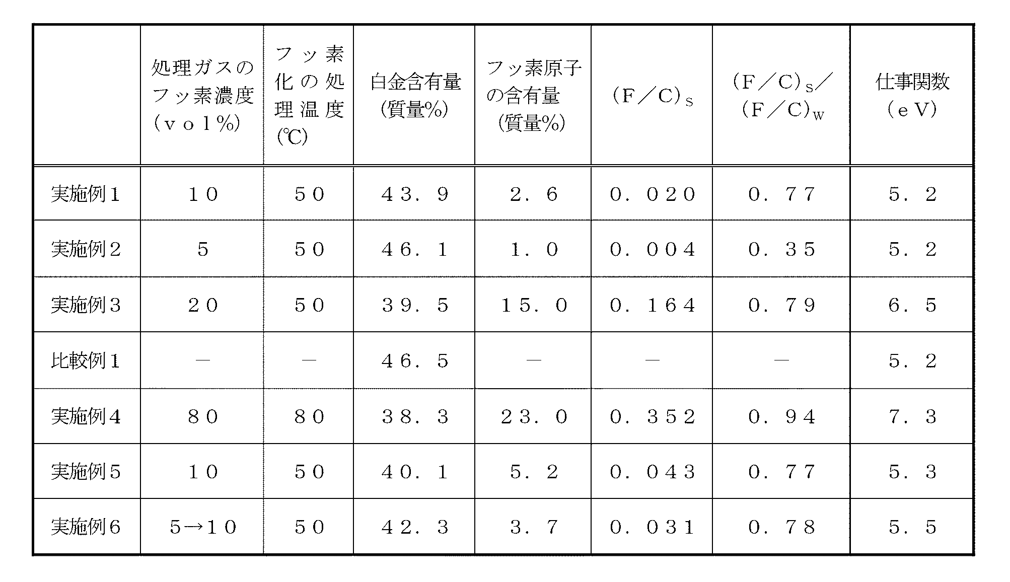
- Example 2 In this example, the concentration of the fluorine gas in the processing gas when performing the fluorination treatment was changed to 5 vol%. Other than that was carried out similarly to Example 1, and produced the catalyst for fuel cells which concerns on a present Example.
- Example 3 In this example, the concentration of the fluorine gas in the processing gas when performing the fluorination treatment was changed to 20 vol%. Other than that was carried out similarly to Example 1, and produced the catalyst for fuel cells which concerns on a present Example.
- Comparative Example 1 a platinum-supported catalyst (product number: TEC10E50E, manufactured by Tanaka Kikinzoku Co., Ltd.) in which platinum is supported on a ketjen black (support) that has not been fluorinated is used as a fuel cell catalyst.
- TEC10E50E manufactured by Tanaka Kikinzoku Co., Ltd.
- Example 4 In this example, the concentration of the fluorine gas in the processing gas when performing the fluorination treatment was changed to 80 vol%, and the processing temperature was changed to 80 ° C. Other than that was carried out similarly to Example 1, and produced the catalyst for fuel cells which concerns on a present Example.
- Example 5 a platinum-supported catalyst (product number: TEC10E50E, manufactured by Tanaka Kikinzoku Co., Ltd.) in which platinum was supported on the ketjen black (support) that was not fluorinated was fluorinated. Further, the concentration of the fluorine gas in the processing gas when performing the fluorination treatment was changed to 10 vol%. Other than that was carried out similarly to Example 1, and produced the catalyst for fuel cells which concerns on a present Example.
- TEC10E50E manufactured by Tanaka Kikinzoku Co., Ltd.
- Example 6 In this example, the fuel cell catalyst obtained in Example 2 was fluorinated again. The conditions for the fluorination treatment again were the same as in Example 1, and a fuel cell catalyst according to this example was produced.
- Platinum content in fuel cell catalyst In the fuel cell catalysts obtained in Examples 1 to 6 and Comparative Example 1, the platinum content relative to the total mass of each fuel cell catalyst was determined. That is, each fuel cell catalyst was burned in an oxygen atmosphere at 800 ° C. using an electric furnace. The platinum content was calculated from the weight before combustion, with the residual amount after combustion as the amount of platinum. The results are shown in Table 1.
- the fuel cell catalysts obtained in Examples 1 to 6 were quantitatively analyzed for fluorine atoms and carbon atoms on their surfaces. Quantitative analysis was performed by X-ray photoelectron spectroscopy using a multifunctional scanning X-ray photoelectron spectrometer (Versa Probe III, manufactured by ULVAC-PHI Co., Ltd.). The measurement conditions were X-ray source: AlK ⁇ ray, path energy: 112 eV, step energy: 0.05 eV, and detection angle: 45 °.
- each fuel cell catalyst was combusted in a flask container having a capacity of 500 mL sealed with oxygen gas. Subsequently, the gas generated by the combustion is absorbed in the sample solution (1.7 mmol / L sodium bicarbonate mixed solution of 1.8 mmol / L sodium carbonate) in the flask, and the fluorine ions contained in the test solution are absorbed.
- the content was quantified by ion chromatography (Dionex Corp. ICS-1000, column AS-23).
- the fluorine atom content in each fuel cell catalyst was calculated from the quantified fluorine ion content. Further, the amount obtained by removing the platinum content converted based on the above-mentioned platinum content and the fluorine atom content in the entire fuel cell catalyst from the mass of the fuel cell catalyst is calculated as carbon in the entire fuel cell catalyst. Calculated as the atomic content. Thereby, the ratio (F / C) W of the number of fluorine atoms to the number of carbon atoms in each fuel cell catalyst was calculated, and (F / C) S / (F / C) W was calculated. . The results are shown in Table 1.
- the work functions of the fuel cell catalysts of Examples 1 to 6 and Comparative Example 1 were determined.
- the work function was determined by ultraviolet photoelectron spectroscopy using a multifunction scanning X-ray photoelectron spectrometer (Versa Probe III, manufactured by ULVAC-PHI Co., Ltd.). Measurement conditions were as follows: ultraviolet ray source: HeI line, pass energy: 1.3 eV, step energy: 0.005 eV, and detection angle: 90 °.
- the work function of each fuel cell catalyst was calculated by obtaining the energy difference between the binding energy and the vacuum level. The results are shown in Table 1.
- a mixed solvent having a volume ratio of 1: 1 of ultrapure water and 2-propanol was added to each of the fuel cell catalyst and the ionomer mixture. At this time, the mixed solvent was added so that the solid content of the fuel cell catalyst and the ionomer was 5% by mass. Thereafter, the fuel cell catalyst and ionomer were dispersed in an ultrasonic homogenizer for 30 minutes to prepare catalyst inks according to Examples 1 to 6 and Comparative Example 1.
- each of the produced catalyst inks was applied to a PTFE (polytetrafluoroethylene) sheet and dried.
- PTFE polytetrafluoroethylene
- the cathode-side electrode catalyst layers according to Examples 1 to 6 and Comparative Example 1 were formed on the PTFE sheet.
- the coating amount of the catalyst ink was set so that the platinum basis weight of the electrode catalyst layer to be formed was 0.25 mg / cm 2 .
- ⁇ Preparation of anode side electrode catalyst layer> A commercially available platinum-supported catalyst (product number: TEC10E50E, Tanaka Kikinzoku Co., Ltd.) was used, and the platinum-supported catalyst was weighed so that the platinum content was 16 mg. Next, Nafion (registered trademark) solution (made by DuPont, DE520CS Type) as an ionomer was added. The addition of the ionomer was set to 100% by mass with respect to the mass of the carrier excluding platinum in the fuel cell catalyst.
- a mixed solvent in which the volume ratio of ultrapure water and 2-propanol was 1: 1 was added to the fuel cell catalyst and ionomer mixture. At this time, the mixed solvent was added so that the solids content of the platinum-supported catalyst and ionomer was 5% by mass. Thereafter, the platinum-supported catalyst and ionomer were dispersed with an ultrasonic homogenizer for 30 minutes to prepare a catalyst ink.
- the produced catalyst ink was applied to a PTFE sheet and dried. Thereby, the anode side electrode catalyst layer was formed on the PTFE sheet.
- the coating amount of the catalyst ink was set so that the platinum basis weight of the electrode catalyst layer to be formed was 0.25 mg / cm 2 .
- the anode side electrode catalyst layer formed on the PTFE sheet and the cathode side electrode catalyst layer formed on the PTFE sheet were cut into 1 cm squares, respectively, and each of them was made of a solid polymer electrolyte membrane (NR-211, DuPont). A laminate was produced by laminating on both sides.
- this laminate was pressed at 150 ° C. for 3 minutes at a pressure of 1.2 MPa, and the anode-side electrode catalyst layer and the cathode-side electrode catalyst layer formed on the PTFE sheet were transferred to the solid polymer electrolyte membrane. . Thereafter, the PTFE sheet was peeled off.
- membrane electrode assemblies using the fuel cell catalysts according to Examples 1 to 6 and Comparative Example 1 were produced.
- the anode-side electrode catalyst layer and the cathode-side electrode catalyst layer each had a thickness of 7 ⁇ m, and the solid polymer electrolyte membrane had a thickness of 25 ⁇ m.
- a pair of gas diffusion layers (TGP-H-060, manufactured by Toray Industries, Inc.) was disposed so as to sandwich each membrane electrode assembly, and the gas diffusion layers (thickness 190 ⁇ m) were laminated.
- Humidity control was performed so that the temperature of the fuel cell was 80 ° C. and the relative humidity in the cell was 100% RH, and nitrogen gas was supplied to the anode side and the cathode side, respectively.
- the potential scan was repeated in the potential range of 1.0 to 1.5 V at a potential scan speed of 0.5 V / second, and this was set as a potential scan cycle that imitated starting and stopping of each fuel cell. .
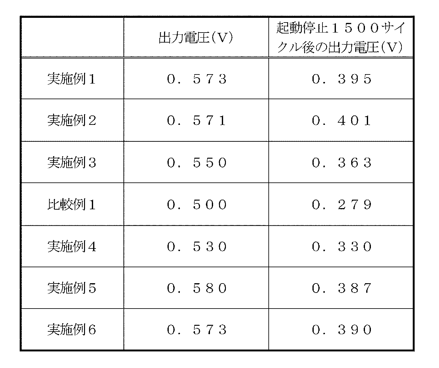
- the output voltage of each fuel cell was measured after 1500 cycles. The measurement method was the same as described above. The results are shown in Table 2.
Landscapes
- Chemical & Material Sciences (AREA)
- Chemical Kinetics & Catalysis (AREA)
- Electrochemistry (AREA)
- General Chemical & Material Sciences (AREA)
- Engineering & Computer Science (AREA)
- Materials Engineering (AREA)
- Sustainable Development (AREA)
- Life Sciences & Earth Sciences (AREA)
- Manufacturing & Machinery (AREA)
- Sustainable Energy (AREA)
- Organic Chemistry (AREA)
- Inert Electrodes (AREA)
- Catalysts (AREA)
- Fuel Cell (AREA)
Abstract
Description

(F/C)S/(F/C)W<0.8 ・・・(1)
(但し、(F/C)Sは、燃料電池用触媒の表面における炭素原子の原子数に対するフッ素原子の原子数の比を表し、(F/C)Wは、燃料電池用触媒の全体における炭素原子の原子数に対するフッ素原子の原子数の比を表す。)
本実施の形態に係る燃料電池用触媒は、触媒活性種と、当該触媒活性種を担持する担体とを少なくとも有する担持体の構造を有している。また、触媒活性種及び担体の少なくとも何れか一方には、フッ素原子が含まれる。本実施の形態の燃料電池用触媒は、固体高分子型燃料電池等に好適に用いることができる。
先ず、燃料電池用触媒を構成する担体について説明する。
本明細書に於いて「担体」とは、アノード側電極触媒層及び/又はカソード側電極触媒層(以下、単に「電極触媒層」ということがある。)に於いて、触媒活性種の過度な凝集を抑制すること等を目的として用いられる電子伝導性物質を意味する。
次に、本実施の形態に係る触媒活性種について以下に説明する。
本明細書に於いて「触媒活性種」とは、燃料電池内に於ける電気化学反応に於いて、触媒機能を発揮し得る物質を意味する。本実施の形態の触媒活性種は、具体的には、白金、白金合金、及びコアシェル触媒からなる群より選ばれる少なくとも1種の活性種からなる。
本実施の形態において、担体である炭素原子の原子数に対する、触媒活性種及び担体の少なくとも何れか一方に含まれるフッ素原子の原子数の比は、次式(1)の関係を満たすことが好ましい。
(但し、(F/C)Sは、燃料電池用触媒の表面における炭素原子の原子数に対するフッ素原子の原子数の比を表し、(F/C)Wは、燃料電池用触媒の全体における炭素原子の原子数に対するフッ素原子の原子数の比を表す。)
本実施の形態に係る燃料電池用触媒の仕事関数は4~7.5eVであることが好ましく、4~7eVであることがより好ましく、5~6.5eVであることが特に好ましい。燃料電池用触媒の仕事関数が4eV以上であると、電子伝導性を良好に維持することができる。その一方、燃料電池用触媒の仕事関数が7.5eV以下であると、電子伝導性を損なわずに、耐酸化性の向上を図ることができる。尚、燃料電池用触媒の仕事関数は、紫外線光電子分光法等によって測定可能である。
次に、本実施の形態に係る燃料電池用触媒の製造方法について、以下に説明する。
本実施の形態に係る燃料電池用触媒の製造方法としては、担体をフッ素化処理した後に触媒活性種を担持する方法A、担体に触媒活性種を担持した後にフッ素化処理を行う方法B、フッ素化処理した触媒活性種を担体に担持する方法Cが挙げられる。さらに、本実施の形態に於いては、前記方法A及び方法Bに対し、再フッ素化処理を行ってもよい。
触媒活性種を担体に担持させる方法としては特に限定されず、公知の方法を採用することができる。例えば、触媒活性種の前駆体を溶解させた反応液に、担体としての炭素材料を分散させる。分散方法については特に限定されず、公知の方法を採用することができる。次に、この反応液に適切な還元剤を投入し、溶存している前駆体の金属イオン種を還元することにより触媒活性種を担体表面に担持させる。続いて、この反応液を固液分離した後、固形分を乾燥させる。これにより、触媒活性種の担持体が得られる。尚、触媒活性種の炭素材料への担持は、当該触媒活性種及び炭素材料にフッ素原子が導入されているか否かに関わらず可能である。
触媒活性種、炭素材料、又は触媒活性種を担持した炭素材料へのフッ素原子の導入は、フッ素化処理を行うことにより可能である。フッ素化処理を行うことにより、炭素材料の表面や細孔内部に、炭素-フッ素結合によるフッ素基が導入される。従って、例えば、炭素六角網面のエッジ部分に水酸基、カルボニル基又はカルボキシル基等の含酸素官能基を付与する酸化処理とは異なり、炭素材料にダメージを与えたり分解させる等の構造欠陥が生じることなく、その表面をフッ素化することができる。
前記再フッ素化処理は、フッ素化処理された触媒活性種を、フッ素化処理されていない炭素材料に担持したもの、又はフッ素化処理されていない触媒活性種を、フッ素化処理された炭素材料に担持したものに対し、フッ素原子を導入することを目的として行われる工程である。
次に、本実施の形態の燃料電池用触媒を用いた燃料電池について、図1に基づき以下に説明する。図1は、本実施の形態に係る単一セル構造の燃料電池を表す概略断面図である。
本実施の形態の膜電極接合体10は、固体高分子電解質膜11と、当該固体高分子電解質膜11の両面に設けられた一対の電極触媒層12、より具体的にはアノード側電極触媒層(燃料極)12a及びカソード側電極触媒層(空気極)12bとを少なくとも備える。
ガス拡散層13は、電子伝導性を有する多孔質体からなる。電子伝導性を有することにより、燃料電池の反応に由来する電子の移動を可能にしている。また、多孔質体からなることにより、アノード側ガス拡散層13aでは燃料ガスに含まれる水素ガスの良好な拡散を可能にし、カソード側ガス拡散層13bでは酸化剤ガスに含まれる空気の良好な拡散を可能にする。更に、カソード側電極触媒層12bでは、副生する水を排出するための排出路としての機能も果たす。
セパレータ14の材料としては特に限定されないが、燃料ガスに含まれる水素ガス及び酸化剤ガスに含まれる空気に対して不活性であり、ガスシール性が高く、耐食性を付与するものが好ましい。また、電子伝導性が高く、機械的強度に優れたものが好ましい。そのような材料としては、例えば、等方性カーボンや炭素板等からなるカーボン製のものが挙げられる。また、ステンレス等の金属製からなるものも挙げられる。更に、ステンレス、チタン又はアルミニウム等の金属製の部材の表面に、カーボン材料がコーティングされたものを用いてもよい。尚、セパレータ14は燃料である水素と空気を分離する機能を有するものが好ましく、これにより表面にガスの流路を成形することができる。また、セパレータ14の厚さとしては特に限定されず、適宜必要に応じて設定することができる。
ガスケット15は、電極触媒層12及びガス拡散層13の端部に隣接する位置であって、固体高分子電解質膜11とセパレータ14との間に備えられる。燃料電池1がガスケット15を備えることにより、電極触媒層12及びガス拡散層13の端部がシールされ、供給されるガスが、電極触媒層12及びガス拡散層13の端部から漏洩するのを防止することができる。
<担体のフッ素化処理>
PTFE(ポリテトラフルオロエチレン)製容器(容量5mL)に、担体として、比表面積が800m2/gのカーボンブラック(商品名;ケッチェンブラックEC300J、ライオン・スペシャリティー・ケミカルズ株式会社)0.300gを添加し、本容器を電解研磨されたSUS316L製チャンバー(容量30mL)内に設置した。次に、チャンバー内を真空にした後に、窒素ガスを導入した(真空置換)。さらに、窒素気流(20mL/min)下、昇温速度4℃/minでチャンバー内の温度を250℃に昇温させ、1時間の恒温処理を行った。その後、チャンバー内の温度を50℃まで冷却し、1時間の恒温処理を行った。
塩化白金酸六水和物(H2PtCl6・6H2O)0.797gを溶解させた水溶液100mLに対し、フッ素化処理されたカーボンブラック0.300gを添加し、超音波ホモジナイザーを用いて担体を水溶液中に分散させた。この分散液に、1mol/Lの水酸化ナトリウム水溶液を添加し、pHを11~12の範囲に調節した。
本実施例においては、フッ素化処理を行う際の処理ガスにおけるフッ素ガスの濃度を5vol%に変更した。それ以外は、実施例1と同様にして、本実施例に係る燃料電池用触媒を作製した。
本実施例においては、フッ素化処理を行う際の処理ガスにおけるフッ素ガスの濃度を20vol%に変更した。それ以外は、実施例1と同様にして、本実施例に係る燃料電池用触媒を作製した。
本比較例においては、フッ素化処理がされていないケッチェンブラック(担体)に白金が担持された白金担持触媒(品番:TEC10E50E、田中貴金属株式会社製)を、燃料電池用触媒に用いた。
本実施例においては、フッ素化処理を行う際の処理ガスにおけるフッ素ガスの濃度を80vol%に変更し、処理温度を80℃に変更した。それ以外は、実施例1と同様にして、本実施例に係る燃料電池用触媒を作製した。
本実施例においては、フッ素化処理がされていない前記ケッチェンブラック(担体)に白金が担持された白金担持触媒(品番:TEC10E50E、田中貴金属株式会社製)をフッ素化処理した。また、フッ素化処理を行う際の処理ガスにおけるフッ素ガスの濃度を10vol%に変更した。それ以外は、実施例1と同様にして、本実施例に係る燃料電池用触媒を作製した。
本実施例においては、実施例2で得られた燃料電池用触媒を、再度フッ素化処理した。再度フッ素化処理する条件は、実施例1と同様にして、本実施例に係る燃料電池用触媒を作製した。
実施例1~6及び比較例1で得られた燃料電池用触媒において、それぞれの燃料電池用触媒の全質量に対する白金含有率を求めた。すなわち、電気炉を用い、800℃の酸素雰囲気下で各燃料電池用触媒を燃焼させた。燃焼後の残分量を白金量として、燃焼前の重量から白金含量を算出した。結果を表1に示す。
実施例1~6で得られた燃料電池用触媒について、それらの表面のフッ素原子と炭素原子の定量分析を行った。定量分析は、多機能走査型X線光電子分光分析装置(アルバック・ファイ株式会社製、Versa ProbeIII)を用いて、X線光電子分光法により行った。測定条件としては、X線源:AlKα線、パスエネルギー:112eV、ステップエネルギー:0.05eV、検出角度:45°とした。さらに、C1s、F1sの光電子分光スペクトルのピーク強度から、各燃料電池用触媒の表面のフッ素原子と炭素原子の原子数の比(F/C)Sを算出した。結果を表1に示す。
実施例1~6で得られた燃料電池用触媒について、当該燃料電池用触媒全体のフッ素原子と炭素原子の定量分析を行った。定量分析は、燃焼フラスコ法により行った。
実施例1~6及び比較例1の燃料電池用触媒について、それぞれの仕事関数を求めた。仕事関数は、多機能走査型X線光電子分光分析装置(アルバック・ファイ株式会社製、Versa Probe III)を用いて、紫外線光電子分光法により求めた。また、測定条件は、紫外線源:HeI線、パスエネルギー:1.3eV、ステップエネルギー:0.005eV、検出角度:90°とした。そして、結合エネルギーと真空準位のエネルギー差を求めることで、各燃料電池用触媒の仕事関数を算出した。結果を表1に示す。
実施例1~6又は比較例1の燃料電池用触媒における白金含有率をもとに、白金の含有量が16mgになる様に燃料電池用触媒をそれぞれ秤量した。次に、アイオノマーとしてのナフィオン(登録商標)溶液(デュポン製、DE520CS Type)をそれぞれ添加した。アイオノマーの添加は、燃料電池用触媒における白金とフッ素原子を除く担体の質量に対して、70質量%になるようにした。
市販の白金担持触媒(品番:TEC10E50E、田中貴金属株式会社)を用い、白金の含有量が16mgになる様に白金担持触媒を秤量した。次に、アイオノマーとしてのナフィオン(登録商標)溶液(デュポン製、DE520CS Type)を添加した。アイオノマーの添加は、燃料電池用触媒における白金を除く担体の質量に対して、100質量%になるようにした。
PTFEシート上に形成されたアノード側電極触媒層、及びPTFEシート上に形成されたカソード側電極触媒層をそれぞれ1cm角に切り出し、それぞれを固体高分子電解質膜(NR-211、デュポン株式会社)の両面に積層して積層体を作製した。
実施例1~6及び比較例1に係る燃料電池セルについて、初期の出力電圧の評価を行った。
すなわち、得られた燃料電池セルに、常圧にてアノード側に水素ガス(利用率5%)を供給し、カソード側に空気を供給することで酸素(利用率5%)を供給した。セル内の相対湿度は60%RHであった。セル温度80℃において、運転時の電流密度が1.0A/cm-2における運転初期の出力電圧(初期セル電圧)を測定した。結果を表2に示す。
燃料電池セルの温度を80℃にし、セル内の相対湿度が100%RHになるように加湿制御して、アノード側及びカソード側にそれぞれ窒素ガスを供給した。
10 膜電極接合体
11 固体高分子電解質膜
12 電極触媒層
12a アノード側電極触媒層
12b カソード側電極触媒層
13 ガス拡散層
13a アノード側ガス拡散層
13b カソード側ガス拡散層
14 セパレータ
15 ガスケット
Claims (9)
- 触媒活性種と、前記触媒活性種を担持する担体とを少なくとも有する燃料電池用触媒であって、
前記触媒活性種が白金、白金合金、及び白金と異なる金属のコアを、白金を含むシェルで被覆したコアシェル触媒からなる群より選ばれる少なくとも1種であり、
前記担体が炭素材料であり、
前記触媒活性種及び前記担体の少なくとも何れか一方はフッ素原子を含む燃料電池用触媒。 - 前記担体に含まれる炭素原子の原子数に対する、前記触媒活性種及び前記担体の少なくとも何れか一方に含まれる前記フッ素原子の原子数の比が、次式(1)に示す関係を満たす請求項1に記載の燃料電池用触媒。
(F/C)S/(F/C)W<0.8 ・・・(1)
(但し、(F/C)Sは、燃料電池用触媒の表面における炭素原子の原子数に対するフッ素原子の原子数の比を表し、(F/C)Wは、燃料電池用触媒の全体における炭素原子の原子数に対するフッ素原子の原子数の比を表す。) - 前記(F/C)Sが0.4未満である請求項2に記載の燃料電池用触媒。
- 前記炭素材料が、グラファイト、酸化グラファイト、カーボンブラック、黒鉛化カーボンブラック、ダイアモンドライクカーボン、フラーレン、単層カーボンナノチューブ、多層カーボンナノチューブ、カーボンナノホーン、カーボンナノウォール、カーボンナノファイバー、カーボンナノブラシ、単層グラフェン、多層グラフェン、及び酸化グラフェンからなる群より選ばれる少なくとも1種である請求項1~3の何れか1項に記載の燃料電池用触媒。
- 固体高分子電解質膜と、当該固体高分子電解質膜の両表面に配置された電極触媒層とを少なくとも有する燃料電池用膜電極接合体であって、
前記電極触媒層が、請求項1~4の何れか1項に記載の燃料電池用触媒と、当該燃料電池用触媒を被覆するアイオノマーとを少なくとも有する燃料電池用膜電極接合体。 - 前記アイオノマーがフッ素系樹脂である請求項5に記載の燃料電池用膜電極接合体。
- 前記アイオノマーが芳香族系炭化水素樹脂である請求項5に記載の燃料電池用膜電極接合体。
- 前記アイオノマーがイオン液体である請求項5に記載の燃料電池用膜電極接合体。
- 請求項5~8の何れか1項に記載の燃料電池用膜電極接合体を備える燃料電池。
Priority Applications (5)
| Application Number | Priority Date | Filing Date | Title |
|---|---|---|---|
| EP19793800.4A EP3787080A4 (en) | 2018-04-25 | 2019-04-15 | FUEL CELL CATALYST, MEMBRANE ELECTRODE ARRANGEMENT FOR FUEL CELL AND FUEL CELL WITH IT |
| CA3097681A CA3097681A1 (en) | 2018-04-25 | 2019-04-15 | Fuel cell catalyst, membrane electrode assembly for fuel cell, and fuel cell provided therewith |
| CN201980012135.0A CN111837272B (zh) | 2018-04-25 | 2019-04-15 | 燃料电池用催化剂、燃料电池用膜电极接合体及具备该燃料电池用膜电极接合体的燃料电池 |
| US17/043,753 US11469424B2 (en) | 2018-04-25 | 2019-04-15 | Fuel cell catalyst, membrane electrode assembly for fuel cell, and fuel cell including the same |
| KR1020207029299A KR102648629B1 (ko) | 2018-04-25 | 2019-04-15 | 연료 전지용 촉매, 연료 전지용 막전극 접합체 및 그것을 구비한 연료 전지 |
Applications Claiming Priority (2)
| Application Number | Priority Date | Filing Date | Title |
|---|---|---|---|
| JP2018-084134 | 2018-04-25 | ||
| JP2018084134 | 2018-04-25 |
Publications (1)
| Publication Number | Publication Date |
|---|---|
| WO2019208310A1 true WO2019208310A1 (ja) | 2019-10-31 |
Family
ID=68294512
Family Applications (1)
| Application Number | Title | Priority Date | Filing Date |
|---|---|---|---|
| PCT/JP2019/016199 Ceased WO2019208310A1 (ja) | 2018-04-25 | 2019-04-15 | 燃料電池用触媒、燃料電池用膜電極接合体及びそれを備えた燃料電池 |
Country Status (7)
| Country | Link |
|---|---|
| US (1) | US11469424B2 (ja) |
| EP (1) | EP3787080A4 (ja) |
| JP (1) | JP7190171B2 (ja) |
| KR (1) | KR102648629B1 (ja) |
| CN (1) | CN111837272B (ja) |
| CA (1) | CA3097681A1 (ja) |
| WO (1) | WO2019208310A1 (ja) |
Cited By (4)
| Publication number | Priority date | Publication date | Assignee | Title |
|---|---|---|---|---|
| JP2019194977A (ja) * | 2018-04-25 | 2019-11-07 | ステラケミファ株式会社 | 燃料電池用触媒、その製造方法、燃料電池用膜電極接合体及びそれを備えた燃料電池 |
| CN112713281A (zh) * | 2021-01-13 | 2021-04-27 | 范钦柏 | 一种燃料电池双极板及燃料电池堆 |
| JPWO2023277148A1 (ja) * | 2021-07-01 | 2023-01-05 | ||
| US20230175150A1 (en) * | 2021-11-01 | 2023-06-08 | Daegu Gyeongbuk Institute Of Science And Technology | Composite comprising platinum-alkaline earth metal alloy, fuel cell and water electrolyzer comprising the same and manufacturing method thereof |
Families Citing this family (11)
| Publication number | Priority date | Publication date | Assignee | Title |
|---|---|---|---|---|
| KR102387596B1 (ko) * | 2018-12-26 | 2022-04-18 | 코오롱인더스트리 주식회사 | 촉매, 이의 제조 방법, 이를 포함하는 전극, 이를 포함하는 막-전극 어셈블리, 및 이를 포함하는 연료 전지 |
| CN112421058B (zh) * | 2020-11-26 | 2022-08-12 | 西北工业大学 | 一种PdAgF纳米合金甲酸盐氧化催化剂及制备和使用方法 |
| KR20220078747A (ko) * | 2020-12-03 | 2022-06-13 | 현대자동차주식회사 | 연료전지용 복합 촉매 및 이의 제조방법 |
| KR20220103288A (ko) * | 2021-01-15 | 2022-07-22 | 현대자동차주식회사 | 인터메탈릭 촉매 및 이의 제조 방법 |
| CN113066998A (zh) * | 2021-03-26 | 2021-07-02 | 广州费舍尔人工智能技术有限公司 | 一种氮掺杂空心碳球负载氟化钴酸铜电极催化剂 |
| WO2023018725A1 (en) * | 2021-08-10 | 2023-02-16 | 1S1 Energy, Inc. | Modification of perfluorinated polymers, ionomers, and membranes using perfluorinated linkers |
| US11539063B1 (en) * | 2021-08-17 | 2022-12-27 | Amogy Inc. | Systems and methods for processing hydrogen |
| JP7401493B2 (ja) * | 2021-09-10 | 2023-12-19 | 株式会社Screenホールディングス | 触媒インクの製造方法、および膜電極接合体の製造方法 |
| JP7788691B2 (ja) * | 2022-02-18 | 2025-12-19 | 学校法人同志社 | 触媒組成物、触媒担持体、燃料電池用カソード電極および燃料電池ならびに触媒組成物の製造方法および触媒担持体の製造方法 |
| CN116344842B (zh) * | 2023-03-13 | 2025-11-21 | 北京化工大学 | 一种碳载低铂合金纳米晶催化剂及其制备方法和应用及燃料电池 |
| CN119905602B (zh) * | 2024-12-17 | 2025-11-21 | 北京石墨烯技术研究院有限公司 | 铂复合催化剂及其制备方法、膜电极组件及燃料电池 |
Citations (7)
| Publication number | Priority date | Publication date | Assignee | Title |
|---|---|---|---|---|
| JPH0414761A (ja) * | 1990-05-07 | 1992-01-20 | Fuji Electric Co Ltd | リン酸型燃料電池用電極触媒層の製造方法 |
| JP2006102568A (ja) * | 2004-09-30 | 2006-04-20 | Toyota Central Res & Dev Lab Inc | 電極触媒及びその製造方法、並びに、燃料電池 |
| JP2006210282A (ja) * | 2005-01-31 | 2006-08-10 | Materials & Energy Research Institute Tokyo Ltd | 燃料電池の燃料極の製造方法及び燃料電池 |
| JP2007149513A (ja) * | 2005-11-29 | 2007-06-14 | National Institute Of Advanced Industrial & Technology | 固体高分子形燃料電池用触媒担体 |
| JP2012079489A (ja) | 2010-09-30 | 2012-04-19 | Gs Yuasa Corp | 固体高分子形燃料電池用触媒、それを使用した電極および電池 |
| WO2016021399A1 (ja) * | 2014-08-05 | 2016-02-11 | 田中貴金属工業株式会社 | 固体高分子形燃料電池用の触媒及びその製造方法 |
| WO2016190248A1 (ja) | 2015-05-25 | 2016-12-01 | 旭硝子株式会社 | 含フッ素カーボン粒子、その製造方法、およびその使用 |
Family Cites Families (13)
| Publication number | Priority date | Publication date | Assignee | Title |
|---|---|---|---|---|
| JPS5115193B1 (ja) * | 1971-03-19 | 1976-05-14 | ||
| JP3291803B2 (ja) | 1992-11-06 | 2002-06-17 | ダイキン工業株式会社 | フッ化カーボン粒子およびその製法ならびに用途 |
| JPH10270052A (ja) | 1997-03-27 | 1998-10-09 | Toyota Central Res & Dev Lab Inc | ガス反応系あるいはガス生成系電池用電極の製造方法 |
| JP2005243583A (ja) * | 2004-02-27 | 2005-09-08 | Tama Tlo Kk | 燃料電池 |
| JP5115193B2 (ja) * | 2005-02-07 | 2013-01-09 | 株式会社Gsユアサ | 触媒担持粉末、及びその製造方法 |
| JP2006216503A (ja) | 2005-02-07 | 2006-08-17 | Nissan Motor Co Ltd | 固体高分子型燃料電池の触媒層 |
| US20110003071A1 (en) | 2008-02-29 | 2011-01-06 | Basf Se | Catalyst ink comprising an ionic liquid and its use in the production of electrodes, ccms, gdes and meas |
| JP5482095B2 (ja) * | 2008-10-30 | 2014-04-23 | ソニー株式会社 | 白金含有触媒を含有する電極及びその製造方法、並びに、電気化学デバイス |
| JP5877494B2 (ja) * | 2011-08-25 | 2016-03-08 | 日産自動車株式会社 | 燃料電池用電極触媒層、燃料電池用電極、燃料電池用膜電極接合体及び燃料電池 |
| JP5635212B2 (ja) * | 2012-03-26 | 2014-12-03 | 昭和電工株式会社 | 燃料電池用電極触媒の製造方法、燃料電池用電極触媒およびその用途 |
| US20180261866A1 (en) * | 2015-09-09 | 2018-09-13 | Nissan Motor Co., Ltd. | Fuel cell electrode catalyst layer and manufacturing method therefor, and membrane electrode assembly, fuel cell, and vehicle using catalyst layer |
| EP3473596A4 (en) * | 2016-06-15 | 2019-07-10 | Tohoku University | CARBON MATERIAL AND METHOD FOR THE PRODUCTION THEREOF |
| EP3787080A4 (en) | 2018-04-25 | 2021-06-23 | Stella Chemifa Corporation | FUEL CELL CATALYST, MEMBRANE ELECTRODE ARRANGEMENT FOR FUEL CELL AND FUEL CELL WITH IT |
-
2019
- 2019-04-15 EP EP19793800.4A patent/EP3787080A4/en active Pending
- 2019-04-15 CA CA3097681A patent/CA3097681A1/en active Pending
- 2019-04-15 KR KR1020207029299A patent/KR102648629B1/ko active Active
- 2019-04-15 US US17/043,753 patent/US11469424B2/en active Active
- 2019-04-15 WO PCT/JP2019/016199 patent/WO2019208310A1/ja not_active Ceased
- 2019-04-15 CN CN201980012135.0A patent/CN111837272B/zh active Active
- 2019-04-15 JP JP2019076934A patent/JP7190171B2/ja active Active
Patent Citations (7)
| Publication number | Priority date | Publication date | Assignee | Title |
|---|---|---|---|---|
| JPH0414761A (ja) * | 1990-05-07 | 1992-01-20 | Fuji Electric Co Ltd | リン酸型燃料電池用電極触媒層の製造方法 |
| JP2006102568A (ja) * | 2004-09-30 | 2006-04-20 | Toyota Central Res & Dev Lab Inc | 電極触媒及びその製造方法、並びに、燃料電池 |
| JP2006210282A (ja) * | 2005-01-31 | 2006-08-10 | Materials & Energy Research Institute Tokyo Ltd | 燃料電池の燃料極の製造方法及び燃料電池 |
| JP2007149513A (ja) * | 2005-11-29 | 2007-06-14 | National Institute Of Advanced Industrial & Technology | 固体高分子形燃料電池用触媒担体 |
| JP2012079489A (ja) | 2010-09-30 | 2012-04-19 | Gs Yuasa Corp | 固体高分子形燃料電池用触媒、それを使用した電極および電池 |
| WO2016021399A1 (ja) * | 2014-08-05 | 2016-02-11 | 田中貴金属工業株式会社 | 固体高分子形燃料電池用の触媒及びその製造方法 |
| WO2016190248A1 (ja) | 2015-05-25 | 2016-12-01 | 旭硝子株式会社 | 含フッ素カーボン粒子、その製造方法、およびその使用 |
Non-Patent Citations (1)
| Title |
|---|
| See also references of EP3787080A4 |
Cited By (9)
| Publication number | Priority date | Publication date | Assignee | Title |
|---|---|---|---|---|
| JP2019194977A (ja) * | 2018-04-25 | 2019-11-07 | ステラケミファ株式会社 | 燃料電池用触媒、その製造方法、燃料電池用膜電極接合体及びそれを備えた燃料電池 |
| US11469424B2 (en) | 2018-04-25 | 2022-10-11 | Stella Chemifa Corporation | Fuel cell catalyst, membrane electrode assembly for fuel cell, and fuel cell including the same |
| JP7190171B2 (ja) | 2018-04-25 | 2022-12-15 | ステラケミファ株式会社 | 燃料電池用触媒、その製造方法、燃料電池用膜電極接合体及びそれを備えた燃料電池 |
| CN112713281A (zh) * | 2021-01-13 | 2021-04-27 | 范钦柏 | 一种燃料电池双极板及燃料电池堆 |
| JPWO2023277148A1 (ja) * | 2021-07-01 | 2023-01-05 | ||
| WO2023277148A1 (ja) * | 2021-07-01 | 2023-01-05 | 凸版印刷株式会社 | イオン液体含浸触媒粒子、燃料電池用膜電極接合体、及び燃料電池 |
| JP7396539B2 (ja) | 2021-07-01 | 2023-12-12 | Toppanホールディングス株式会社 | イオン液体含浸触媒粒子、燃料電池用膜電極接合体、及び燃料電池 |
| US20230175150A1 (en) * | 2021-11-01 | 2023-06-08 | Daegu Gyeongbuk Institute Of Science And Technology | Composite comprising platinum-alkaline earth metal alloy, fuel cell and water electrolyzer comprising the same and manufacturing method thereof |
| US12601072B2 (en) * | 2021-11-01 | 2026-04-14 | Daegu Gyeongbuk Institute Of Science And Technology | Composite containing platinum-alkaline earth metal alloy, fuel cell and water electrolysis cell containing the composite, and method of producing the composite |
Also Published As
| Publication number | Publication date |
|---|---|
| CN111837272A (zh) | 2020-10-27 |
| KR20210002480A (ko) | 2021-01-08 |
| JP7190171B2 (ja) | 2022-12-15 |
| CA3097681A1 (en) | 2019-10-31 |
| US11469424B2 (en) | 2022-10-11 |
| KR102648629B1 (ko) | 2024-03-19 |
| US20210036334A1 (en) | 2021-02-04 |
| EP3787080A4 (en) | 2021-06-23 |
| JP2019194977A (ja) | 2019-11-07 |
| CN111837272B (zh) | 2025-01-14 |
| EP3787080A1 (en) | 2021-03-03 |
Similar Documents
| Publication | Publication Date | Title |
|---|---|---|
| JP7190171B2 (ja) | 燃料電池用触媒、その製造方法、燃料電池用膜電極接合体及びそれを備えた燃料電池 | |
| CA2925618C (en) | Carbon powder for catalyst, catalyst, electrode catalyst layer, membrane electrode assembly, and fuel cell using the carbon powder | |
| EP2990116B1 (en) | Catalyst, electrode catalyst layer using said catalyst, membrane electrode assembly, and fuel cell | |
| EP2990109B1 (en) | Catalyst and electrode catalyst layer for fuel cell having the catalyst | |
| EP2991142B1 (en) | Catalyst, electrode catalyst layer using said catalyst, membrane electrode assembly, and fuel cell | |
| KR100545624B1 (ko) | 연료 전지용 전극 및 그를 이용한 연료 전지 | |
| CN111063896A (zh) | 电化学器件的电极催化剂、膜电极接合体、它们的制造方法和电化学器件的电极催化剂层 | |
| EP2990106B1 (en) | Electrode catalyst layer using catalyst, membrane electrode assembly, and fuel cell | |
| WO2016063968A1 (ja) | 燃料電池用電極触媒及びその製造方法 | |
| KR101309160B1 (ko) | 연료 전지용 촉매층 조성물, 그리고 이를 이용한 연료 전지용 전극, 연료 전지용 전극의 제조 방법, 연료 전지용 막-전극 어셈블리 및 연료 전지 시스템 | |
| WO2012053303A1 (ja) | 固体高分子型燃料電池用電極触媒 | |
| JP6098430B2 (ja) | 固体高分子形燃料電池 | |
| JP7516825B2 (ja) | 固体高分子形燃料電池用触媒層、膜電極接合体及び固体高分子形燃料電池 | |
| JP7002974B2 (ja) | 電極、膜電極接合体、電気化学セル、スタック、燃料電池、車両及び飛翔体 | |
| US20260045516A1 (en) | Electrode catalyst layer, membrane electrode assembly, and polymer electrolyte fuel cell | |
| KR20120136393A (ko) | 연료 전지 전극 촉매층용 슬러리, 전극 촉매층, 막 전극 접합체, 및 연료 전지 | |
| JP2011070925A (ja) | 電解質膜−電極接合体 | |
| JP2007250214A (ja) | 電極触媒とその製造方法 | |
| JP2010027360A (ja) | 高分子電解質膜およびこれを用いた膜電極接合体 | |
| JP2007149461A (ja) | 固体高分子型燃料電池電極用インク | |
| JP2007311029A (ja) | 固体高分子形燃料電池用触媒粉末およびそれを用いた固体高分子形燃料電池 |
Legal Events
| Date | Code | Title | Description |
|---|---|---|---|
| DPE2 | Request for preliminary examination filed before expiration of 19th month from priority date (pct application filed from 20040101) | ||
| 121 | Ep: the epo has been informed by wipo that ep was designated in this application |
Ref document number: 19793800 Country of ref document: EP Kind code of ref document: A1 |
|
| ENP | Entry into the national phase |
Ref document number: 20207029299 Country of ref document: KR Kind code of ref document: A |
|
| ENP | Entry into the national phase |
Ref document number: 3097681 Country of ref document: CA |
|
| NENP | Non-entry into the national phase |
Ref country code: DE |
|
| ENP | Entry into the national phase |
Ref document number: 2019793800 Country of ref document: EP Effective date: 20201125 |
|
| WWG | Wipo information: grant in national office |
Ref document number: 201980012135.0 Country of ref document: CN |