WO2019208385A1 - Soupape de régulation de débit de type champignon - Google Patents
Soupape de régulation de débit de type champignon Download PDFInfo
- Publication number
- WO2019208385A1 WO2019208385A1 PCT/JP2019/016619 JP2019016619W WO2019208385A1 WO 2019208385 A1 WO2019208385 A1 WO 2019208385A1 JP 2019016619 W JP2019016619 W JP 2019016619W WO 2019208385 A1 WO2019208385 A1 WO 2019208385A1
- Authority
- WO
- WIPO (PCT)
- Prior art keywords
- valve body
- valve
- chamber
- flow control
- electric motor
- Prior art date
- Legal status (The legal status is an assumption and is not a legal conclusion. Google has not performed a legal analysis and makes no representation as to the accuracy of the status listed.)
- Ceased
Links
Images



Classifications
-
- F—MECHANICAL ENGINEERING; LIGHTING; HEATING; WEAPONS; BLASTING
- F16—ENGINEERING ELEMENTS AND UNITS; GENERAL MEASURES FOR PRODUCING AND MAINTAINING EFFECTIVE FUNCTIONING OF MACHINES OR INSTALLATIONS; THERMAL INSULATION IN GENERAL
- F16K—VALVES; TAPS; COCKS; ACTUATING-FLOATS; DEVICES FOR VENTING OR AERATING
- F16K39/00—Devices for relieving the pressure on the sealing faces
- F16K39/02—Devices for relieving the pressure on the sealing faces for lift valves
- F16K39/022—Devices for relieving the pressure on the sealing faces for lift valves using balancing surfaces
-
- F—MECHANICAL ENGINEERING; LIGHTING; HEATING; WEAPONS; BLASTING
- F16—ENGINEERING ELEMENTS AND UNITS; GENERAL MEASURES FOR PRODUCING AND MAINTAINING EFFECTIVE FUNCTIONING OF MACHINES OR INSTALLATIONS; THERMAL INSULATION IN GENERAL
- F16K—VALVES; TAPS; COCKS; ACTUATING-FLOATS; DEVICES FOR VENTING OR AERATING
- F16K31/00—Actuating devices; Operating means; Releasing devices
- F16K31/02—Actuating devices; Operating means; Releasing devices electric; magnetic
- F16K31/04—Actuating devices; Operating means; Releasing devices electric; magnetic using a motor
-
- F—MECHANICAL ENGINEERING; LIGHTING; HEATING; WEAPONS; BLASTING
- F16—ENGINEERING ELEMENTS AND UNITS; GENERAL MEASURES FOR PRODUCING AND MAINTAINING EFFECTIVE FUNCTIONING OF MACHINES OR INSTALLATIONS; THERMAL INSULATION IN GENERAL
- F16K—VALVES; TAPS; COCKS; ACTUATING-FLOATS; DEVICES FOR VENTING OR AERATING
- F16K1/00—Lift valves or globe valves, i.e. cut-off apparatus with closure members having at least a component of their opening and closing motion perpendicular to the closing faces
- F16K1/32—Details
-
- F—MECHANICAL ENGINEERING; LIGHTING; HEATING; WEAPONS; BLASTING
- F16—ENGINEERING ELEMENTS AND UNITS; GENERAL MEASURES FOR PRODUCING AND MAINTAINING EFFECTIVE FUNCTIONING OF MACHINES OR INSTALLATIONS; THERMAL INSULATION IN GENERAL
- F16K—VALVES; TAPS; COCKS; ACTUATING-FLOATS; DEVICES FOR VENTING OR AERATING
- F16K1/00—Lift valves or globe valves, i.e. cut-off apparatus with closure members having at least a component of their opening and closing motion perpendicular to the closing faces
- F16K1/32—Details
- F16K1/34—Cutting-off parts, e.g. valve members, seats
- F16K1/36—Valve members
-
- F—MECHANICAL ENGINEERING; LIGHTING; HEATING; WEAPONS; BLASTING
- F16—ENGINEERING ELEMENTS AND UNITS; GENERAL MEASURES FOR PRODUCING AND MAINTAINING EFFECTIVE FUNCTIONING OF MACHINES OR INSTALLATIONS; THERMAL INSULATION IN GENERAL
- F16K—VALVES; TAPS; COCKS; ACTUATING-FLOATS; DEVICES FOR VENTING OR AERATING
- F16K1/00—Lift valves or globe valves, i.e. cut-off apparatus with closure members having at least a component of their opening and closing motion perpendicular to the closing faces
- F16K1/32—Details
- F16K1/48—Attaching valve members to screw-spindles
-
- F—MECHANICAL ENGINEERING; LIGHTING; HEATING; WEAPONS; BLASTING
- F16—ENGINEERING ELEMENTS AND UNITS; GENERAL MEASURES FOR PRODUCING AND MAINTAINING EFFECTIVE FUNCTIONING OF MACHINES OR INSTALLATIONS; THERMAL INSULATION IN GENERAL
- F16K—VALVES; TAPS; COCKS; ACTUATING-FLOATS; DEVICES FOR VENTING OR AERATING
- F16K31/00—Actuating devices; Operating means; Releasing devices
- F16K31/02—Actuating devices; Operating means; Releasing devices electric; magnetic
- F16K31/04—Actuating devices; Operating means; Releasing devices electric; magnetic using a motor
- F16K31/046—Actuating devices; Operating means; Releasing devices electric; magnetic using a motor with electric means, e.g. electric switches, to control the motor or to control a clutch between the valve and the motor
-
- F—MECHANICAL ENGINEERING; LIGHTING; HEATING; WEAPONS; BLASTING
- F16—ENGINEERING ELEMENTS AND UNITS; GENERAL MEASURES FOR PRODUCING AND MAINTAINING EFFECTIVE FUNCTIONING OF MACHINES OR INSTALLATIONS; THERMAL INSULATION IN GENERAL
- F16K—VALVES; TAPS; COCKS; ACTUATING-FLOATS; DEVICES FOR VENTING OR AERATING
- F16K31/00—Actuating devices; Operating means; Releasing devices
- F16K31/44—Mechanical actuating means
- F16K31/50—Mechanical actuating means with screw-spindle or internally threaded actuating means
- F16K31/508—Mechanical actuating means with screw-spindle or internally threaded actuating means the actuating element being rotatable, non-rising, and driving a non-rotatable axially-sliding element
-
- F—MECHANICAL ENGINEERING; LIGHTING; HEATING; WEAPONS; BLASTING
- F16—ENGINEERING ELEMENTS AND UNITS; GENERAL MEASURES FOR PRODUCING AND MAINTAINING EFFECTIVE FUNCTIONING OF MACHINES OR INSTALLATIONS; THERMAL INSULATION IN GENERAL
- F16K—VALVES; TAPS; COCKS; ACTUATING-FLOATS; DEVICES FOR VENTING OR AERATING
- F16K37/00—Special means in or on valves or other cut-off apparatus for indicating or recording operation thereof, or for enabling an alarm to be given
-
- F—MECHANICAL ENGINEERING; LIGHTING; HEATING; WEAPONS; BLASTING
- F16—ENGINEERING ELEMENTS AND UNITS; GENERAL MEASURES FOR PRODUCING AND MAINTAINING EFFECTIVE FUNCTIONING OF MACHINES OR INSTALLATIONS; THERMAL INSULATION IN GENERAL
- F16K—VALVES; TAPS; COCKS; ACTUATING-FLOATS; DEVICES FOR VENTING OR AERATING
- F16K37/00—Special means in or on valves or other cut-off apparatus for indicating or recording operation thereof, or for enabling an alarm to be given
- F16K37/0025—Electrical or magnetic means
- F16K37/0041—Electrical or magnetic means for measuring valve parameters
Definitions
- the present invention relates to a poppet type flow control valve.
- Patent Document 1 discloses a pilot operation type in which the flow rate between the first and second ports is selectively controlled by controlling the pressure of a control chamber provided on the opposite side of the valve body from the valve seat.
- a poppet type flow control valve is disclosed. This poppet type flow control valve has a pilot passage communicating with the control chamber and the second port, and a pilot valve element that operates to open and close the pilot passage. When the pilot valve element is operated by the solenoid actuator, the opening of the pilot passage is adjusted. When the opening of the pilot passage reaches a predetermined size, the valve body is separated from the valve seat.
- the flow rate control of the fluid passing through the pilot passage that is, the flow rate control in the small flow rate range
- Control the pressure in the control chamber In order to perform highly accurate positioning of the valve body, a poppet type flow control valve that employs another method instead of pressure control of the control chamber is desired.
- an object of the present invention is to provide a poppet type flow control valve capable of positioning a valve body with higher accuracy.
- a poppet type flow control valve includes an inlet channel, an outlet channel, a valve chamber provided between the inlet channel and the outlet channel, and the valve A valve housing having a valve seat provided in the chamber; a valve body that is accommodated in the valve housing and moves forward and backward with respect to the valve seat; and moves integrally with the valve body in a forward and backward direction in which the valve body moves forward and backward
- a moving member, an electric motor, a position detector for detecting a rotation angle of the output shaft of the electric motor, and a rotation amount of the output shaft of the electric motor are converted into a linear displacement amount of the moving member in the advancing / retreating direction. Feedback control of the electric motor so that the rotation angle of the output shaft detected by the linear motion conversion mechanism and the position detector corresponds to a predetermined target interval between the valve seat and the valve body And a controller.
- the valve body since the valve body is positioned by feedback control of the electric motor, the valve body can be positioned with respect to the valve seat with high accuracy.
- the poppet type flow control valve is formed on the retraction direction side of the valve body in the valve housing, and is separated from the valve chamber by the valve body, the inlet flow path, and the You may provide the communicating path which connects a back pressure chamber and makes the fluid pressure of the said inlet flow path and the said back pressure chamber equal.
- a force against the force acting in the backward direction on the valve body can be applied in the traveling direction by the fluid pressure in the back pressure chamber equal to the fluid pressure in the inlet channel. For this reason, it is possible to reduce the thrust of the electric motor required to act on the valve body in the traveling direction.
- the valve seat is provided around the opening of the inlet channel with respect to the valve chamber, and the valve housing and the valve body are arranged on the back pressure chamber side.
- the pressure receiving area of the valve body may be formed so as to be larger than the pressure receiving area of the valve body on the inlet channel side.
- the communication path may be formed in the valve body. According to this structure, the structure of a valve housing can be simplified and the enlargement of the whole poppet type flow control valve can be prevented.
- the poppet-type flow control valve includes a biasing member that applies a biasing force to the valve body in the traveling direction, and the valve body has a fluid pressure in the inlet flow path within the outlet flow path.
- the valve body moves in the retraction direction with respect to the moving member. You may move relative.
- Inlet pressure may be lower than outlet pressure.
- the inlet pressure becomes lower than the outlet pressure, so that the force acting on the valve body in the retraction direction acts on the valve body in the traveling direction.
- the pressure exceeds the value, the valve body moves in the backward direction and moves away from the valve seat, so that the fluid in the outlet channel can be supplied to the inlet channel.
- the moving member has an engaging portion for engaging with the valve body, A contact portion that contacts the engagement portion from the advancing direction side, and when the fluid pressure in the inlet channel is higher than the fluid pressure in the outlet channel, the engagement portion is The state of contact with the contact portion is maintained, and the fluid pressure in the inlet channel is lower than the fluid pressure in the outlet channel, and the force acting in the retraction direction on the valve body is applied to the valve body.
- the contact portion may be separated from the engaging portion, and the valve body may move relative to the moving member in the retreat direction.
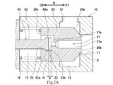
- FIG. 2 is an enlarged view of the valve housing and the valve body shown in FIG. 1, showing a closed state of the flow control valve.
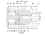
- FIG. 2 is an enlarged view of the valve housing and the valve body shown in FIG. 1, and is a view showing an open state of a flow control valve.
- It is a figure which shows schematic structure of the poppet-type flow control valve concerning 3rd Embodiment of this invention.
- It is a figure which shows schematic structure of the poppet type flow control valve which concerns on 4th Embodiment of this invention.
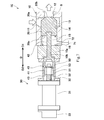
- FIG. 1 is a diagram showing a schematic configuration of a poppet type flow control valve (hereinafter referred to as “flow control valve”) 1 according to the first embodiment.
- the flow control valve 1 ⁇ / b> A includes a valve housing 10, a poppet type valve element 20, and a valve element driving device 30.
- the valve housing 10 has an inlet channel 11 that is a channel of the inlet port, an outlet channel 12 that is a channel of the outlet port, and a valve chamber 13 that is interposed between the inlet channel 11 and the outlet channel 12.
- a valve seat S is provided in the valve chamber 13, and a substantially cylindrical valve body 20 that moves forward and backward with respect to the valve seat S is accommodated in the valve housing 10.
- the valve body 20 advances and retreats in a direction orthogonal to the valve seat S.
- the inlet channel 11 extends from the valve chamber 13 in a direction in which the valve body 20 faces the valve seat S, and the outlet channel 12 has a valve chamber in a direction orthogonal to the direction in which the valve body 20 faces the valve seat S. 13.
- valve seat S is provided around the opening of the inlet channel 11 with respect to the valve chamber 13.
- a cylindrical sliding surface 14 that supports the valve body 20 is formed in the valve housing 10 so as to be slidable in the forward / backward direction D of the valve body 20.
- traveling direction D1 the direction in which the valve body 20 is directed toward the valve seat S among the advancing and retreating directions D of the valve body 20
- regressing direction D2 the direction opposite to the traveling direction D1
- the valve body 20 in a steady state is in a closed state where it is seated (contacted) on the valve seat S as shown in FIG.
- the end of the valve body 20 on the traveling direction D1 side is formed in a taper shape that decreases in diameter in the traveling direction D1.
- a back pressure chamber 15 separated from the valve chamber 13 by the valve body 20 is formed on the side of the valve body 20 in the retraction direction D2 in the valve housing 10. That is, the valve body 20 is between the valve chamber 13 and the back pressure chamber 15. A fluid is guided from the inlet channel 11 into the back pressure chamber 15. More specifically, the valve body 20 is formed with a communication passage 21 that communicates the inlet passage 11 and the back pressure chamber 15 when the valve body 20 is in contact with the valve seat S.
- the communication path 21 communicates the inlet channel 11 and the back pressure chamber 15 and supplies fluid from the inlet channel 11 to the back pressure chamber 15. Thereby, the communication path 21 equalizes the fluid pressure of the inlet flow path 11 and the back pressure chamber 15.
- valve housing 10 and the valve body 20 are the valve on the inlet flow path 11 side when the pressure receiving area S1 of the valve body 20 on the back pressure chamber 15 side is in contact with the valve seat S. It is formed so as to be larger than the pressure receiving area S ⁇ b> 2 of the body 20.
- valve housing 10 and the valve body 20 receive a fluid pressure in the back pressure chamber 15 and are applied with a load that acts in the traveling direction D1.
- the pressure receiving area S1 of the valve body 20 is formed so as to be larger than the pressure receiving area S2 of the valve body 20 to which a load acting on the retreating direction D2 by receiving the fluid pressure in the inlet channel 11 is applied.
- the value obtained by subtracting the cross-sectional area of the shaft portion 42 described later from the cross-sectional area of the back pressure chamber 15 cut perpendicular to the advancing / retreating direction D of the valve body 20 is the inlet of the valve body 20 cut perpendicularly to the advancing / retreating direction D Larger than the cross-sectional area of the flow path 11. For this reason, when the valve body 20 comes into contact with the valve seat S, the force acting on the valve body 20 in the traveling direction D1 due to the fluid pressure in the back pressure chamber 15 is regressed by the fluid pressure in the inlet channel 11. The force acting on the valve body 20 is larger than D2.
- a biasing member 16 is provided that applies a biasing force to the valve body 20 in the traveling direction D1.
- the biasing member 16 is, for example, a compression coil spring.
- the valve body drive device 30 controls the position of the valve body 20 by driving the valve body 20 in contact with the valve seat S in the backward direction D2.
- the valve 20 from the inlet passage 11 is flowed at a flow rate corresponding to the interval between the valve body 20 and the valve seat S.
- a fluid flows to the outlet channel 12 through the chamber 13.
- the valve body driving device 30 servo-controls the electric motor 31 based on the electric motor 31, a position detector 33 that detects the rotation angle of the output shaft 32 of the electric motor 31, and the detection value output from the position detector 33. And a controller 34. That is, the electric motor 31 is a servo motor.
- the position detector 33 is, for example, a resolver. However, the position detector 33 is not limited to a resolver, and may be an encoder or a hall element, for example.
- valve body driving device 30 determines the amount of rotation of the piston 40 (corresponding to the “moving member” of the present invention) 40 that moves integrally with the valve body 20 in the forward / backward direction D and the output shaft 32 of the electric motor 31.
- the linear motion conversion mechanism 50 for converting the linear motion displacement amount in the forward / backward direction D is provided.
- the piston 40 as a whole has a cylindrical shape extending in parallel with the advancing / retreating direction D, and a cylindrical part 41 provided on the retreating direction D2 side and a shaft part 42 provided on the advancing direction D1 side are integrally formed. Yes.
- the cylinder portion 41 of the piston 40 is formed in a substantially bottomed cylindrical shape that opens toward the retraction direction D2.
- the cylindrical portion 41 is inserted into a substantially cylindrical cylinder 43 coupled to the valve housing 10.
- the cylinder 43 is coupled to a wall portion 10a that closes the backward direction D2 side of the back pressure chamber 15.
- the inner peripheral surface of the cylinder 43 and the outer peripheral surface of the piston 40 may not be in contact with each other, and a gap may be provided between the inner peripheral surface of the cylinder 43 and the outer peripheral surface of the piston 40.
- the end of the cylinder 43 on the reverse direction D2 side is coupled to the flange of the electric motor 31.
- the output shaft 32 of the electric motor 31 extends in the forward / backward direction D and is inserted into the cylindrical portion 41 of the piston 40.
- the output shaft 32 is a screw shaft in which a male screw 51 is formed on the outer peripheral surface.
- a nut 52 is fixed to the inner peripheral wall of the cylindrical portion 41 of the piston 40.
- a male screw 51 of the output shaft 32 is screwed into a female screw 53 formed on the inner wall of the nut 52.
- the linear motion conversion mechanism 50 includes a rotation prevention mechanism (not shown) that prevents the cylinder 43 from rotating around the axis of the piston 40.
- a protrusion projecting in the radial direction is formed on the outer peripheral surface of the cylinder portion 41, and a groove portion parallel to the advance / retreat direction D is formed on the inner peripheral surface of the cylinder 43. (Both not shown).
- the rotation prevention mechanism is constituted by these protrusions and grooves, and the protrusions on the outer peripheral surface of the cylinder part 41 are fitted into the grooves on the inner peripheral surface of the cylinder 43, whereby the output shaft 32 of the piston 40 with respect to the cylinder 43 is obtained. Around rotation is prevented.
- the rotation prevention mechanism is not limited to such a configuration.
- a groove portion is formed on the outer peripheral surface of the cylinder portion 41, and a projection portion that fits into the groove portion is formed on the inner peripheral surface of the cylinder 43. Good.
- the linear motion converting mechanism 50 is a ball screw mechanism having the male screw 51 and the nut 52 of the output shaft 32.
- the linear motion conversion mechanism may be, for example, a trapezoidal screw, a sliding screw, or a rack and pinion.
- the shaft portion 42 of the piston 40 extends from the tube portion 41 in the traveling direction D1 and passes through a hole 10b formed in the wall portion 10a of the valve housing 10.
- the shaft portion 42 is engaged with the valve body 20 at the end portion in the traveling direction D1.
- the engagement aspect of the shaft part 42 of the piston 40 and the valve body 20 in the present embodiment will be described with reference to FIGS. 2A and 2B.
- FIG. 2A and 2B are enlarged views of the valve body 20 and the valve housing 10 shown in FIG.
- FIG. 2A shows the closed state of the flow control valve 1A
- FIG. 2B shows a valve open state in which the valve body 20 in the flow control valve 1A is separated from the valve seat S.
- An engagement portion 42 a for the piston 40 to engage with the valve body 20 is provided at the distal end portion in the traveling direction D ⁇ b> 1 of the shaft portion 42 of the piston 40.
- the engaging portion 42 a protrudes radially outward from the shaft portion 42, and has a substantially cylindrical shape whose diameter is larger than the diameter of the shaft portion 42.
- the valve body 20 is formed with a housing chamber 22 for housing the engaging portion 42a.
- the storage chamber 22 is connected to the back pressure chamber 15 through a through hole 23 formed in the valve body 20 and extending in the forward / backward direction D, and a shaft portion 42 is inserted through the through hole 23. Since the diameter of the through hole 23 is smaller than that of the engaging portion 42 a, the engaging portion 42 a is not allowed to escape from the storage chamber 22.
- the valve body 20 is movable relative to the piston 40 in the forward / backward direction D within a predetermined range. Specifically, the interval between the wall portion 22a on the retracting direction D2 side and the wall portion 22b on the traveling direction D1 side in the accommodating chamber 22 is longer than the length in the advancing / retreating direction D of the engaging portion 42a that is substantially cylindrical.
- the storage chamber 22 is formed such that the engagement portion 42a is slidable in the forward / backward direction D between the wall portion 22a and the wall portion 22b in the storage chamber 22.
- the wall portion 22a of the storage chamber 22 is pressed against the engaging portion 42a and is engaged.
- a gap g is formed between the portion 42 a and the wall portion 22 b of the storage chamber 22.
- the wall portion 22a of the storage chamber 22 corresponds to a contact portion of the present invention that contacts the engaging portion 42a from the traveling direction D1 side (in other words, toward the retreating direction D2 side).
- valve body 20 and the piston 40 are integrated in the forward / backward direction D. Move on. As will be described later, when a predetermined condition is satisfied, the valve body 20 moves relative to the piston 40 in the retraction direction D2.
- the communication path 21 described above extends from the end face 20b on the valve body 20 on the traveling direction D1 side in the retreat direction D2 and is connected to the accommodation chamber 22.
- the communication path 21 has a first flow path 21a and a second flow path 21b.
- the first flow path 21 a extends from the end surface 20 b of the valve body 20 to the wall portion 22 b of the storage chamber 22.
- the second flow path 21b extends from the end of the first flow path 21a on the retraction direction D2 side to the end surface 20c of the valve body 20 on the retraction direction D2 side.
- the second flow path 21 b is a groove formed on the wall portion surrounding the accommodation chamber 22 and the inner peripheral surface of the through hole 23.
- the controller 34 corresponds to a predetermined target interval (that is, a predetermined target flow rate) between the valve seat S and the valve body 20 with the rotation angle of the output shaft 32 detected by the position detector 33.
- the electric motor 31 is feedback-controlled so that the rotation angle is obtained.
- the linear motion conversion mechanism 50 converts the rotation amount of the output shaft 32 into the linear motion displacement amount in the forward / backward direction D of the piston 40, so that the position of the piston 40 is the rotation of the output shaft 32.
- the position corresponds to the angle.
- the valve body 20 and the piston 40 move integrally in the forward / backward direction D. For this reason, the valve body 20 moves in the advance / retreat direction D by the amount of linear displacement corresponding to the amount of rotation of the output shaft 32.
- the valve body 20 can be positioned by feedback control of the rotation angle of the output shaft 32 of the electric motor 31 by the controller 34.
- the controller 34 uses a certain point defined in the piston 40 (for example, the tip of the traveling direction D1 of the piston 40) as a reference point, and the position of the reference point reaches a target position corresponding to a predetermined target flow rate. 31 is feedback controlled.
- the controller 34 sets the position of the piston 40 so that the valve body 20 abuts the valve seat S and the wall portion 22a. Is controlled to a position where it is in contact with the engaging portion 42a.
- the controller 34 is a predetermined between the valve seat S and the valve body 20.
- the electric motor 31 is feedback-controlled so that the piston 40 reaches a position corresponding to the target interval (that is, a predetermined target flow rate).
- the flow control valve 1A of the present embodiment is configured so that the valve body 20 is moved to the valve seat S when the fluid pressure in the inlet channel 11 is lower than the fluid pressure in the outlet channel 12 in the closed state shown in FIG. 2A. And an anti-cavitation function that prevents the fluid pressure in the inlet channel 11 from becoming negative pressure by replenishing the hydraulic fluid in the inlet channel 11 from the outlet channel 12.
- valve body 20 acts on the valve body 20 by the difference between the force acting on the traveling direction D1 side by the fluid pressure and the force acting on the retreating direction D2 side, and the urging member 16.
- the urging force is pressed against the valve seat S.
- the fluid pressure in the inlet channel 11 is higher than the fluid pressure in the outlet channel 12, and in this case, the state where the engaging portion 42a is in contact with the wall portion 22a is maintained.
- the flow rate control valve 1A when used to control a hydraulic cylinder that drives a self-weighting element such as a boom lowering of a shovel, for example, if the supply flow rate to the hydraulic cylinder is insufficient, the inlet pressure and the outlet pressure of the flow rate control valve 1A are increased or decreased. May reverse and the inlet pressure may be lower than the outlet pressure. In this case, among the forces acting on the valve body 20, the force acting on the valve body 20 in the backward direction D ⁇ b> 2 due to the taper surface 20 a of the valve body 20 receiving the fluid pressure of the outlet channel 12 becomes relatively large. .
- the fluid pressure in the inlet channel 11 is lower than the fluid pressure in the outlet channel 12, and the force acting on the valve body 20 in the retraction direction D2 exceeds the force acting on the valve body 20 in the traveling direction D1.
- the wall portion 22a is separated from the engaging portion 42a, and the valve body 20 moves relative to the piston 40 in the retreat direction D2. In this way, the fluid in the outlet channel 12 can be supplied to the inlet channel 11.
- the taper surface 20a of the valve body 20 receives the fluid pressure of the outlet flow path 12 and a force acts on the valve body 20 in the retraction direction D2.
- the valve body 20 has a taper surface 20a. It is not limited to. That is, the valve body 20 only needs to be configured to receive the fluid pressure of the outlet flow path 12 and to apply a force to the valve body 20 in the backward direction D2 side as a whole.
- the valve body 20 is positioned by feedback control of the electric motor 31, and therefore the valve body 20 is positioned with respect to the valve seat S with high accuracy. be able to.
- positioning of the valve body S can be performed with higher accuracy and higher response even under conditions of high pressure and large flow rate that are easily affected by the flow force.
- the flow rate can be controlled with high accuracy even in a high pressure and large flow rate application such as a main control valve of a construction machine (mainly a hydraulic excavator).
- a method of positioning the valve body with an electric motor a method of positioning the valve body with the number of input pulses using a stepping motor can be considered.
- the stepping motor has a stationary angle error due to the mechanical accuracy of the stator and the rotor and variations in the resistance of the stator winding, it is difficult to position the valve body with high accuracy as in the present embodiment. It is.
- the position detector 33 used for rotation control of the electric motor 31 that is a servo motor is also used for positioning the valve body 20. For this reason, positioning of the valve body 20 can be realized with a simple configuration.
- the fluid pressure in the inlet flow path 11 and the back pressure chamber 15 is made equal by the communication path 21, so that the valve body 20 acts in the backward direction D ⁇ b> 2 by the fluid pressure in the inlet flow path 11.
- the force against the force can be applied in the traveling direction by the fluid pressure in the back pressure chamber 15 equal to the fluid pressure in the inlet channel 11. For this reason, reducing the thrust of the electric motor 31 required to act on the valve body 20 in the traveling direction D1, for example, the thrust of the electric motor 31 required to bring the valve body 20 into contact with the valve seat S. Can do.
- valve housing 10 and the valve body 20 have a pressure receiving area S1 of the valve body 20 on the back pressure chamber 15 side of the valve body 20 on the inlet flow path 11 side when the valve body 20 is in contact with the valve seat S. It is formed to be larger than the pressure receiving area S2. For this reason, when the valve body 20 is in contact with the valve seat S, the force acting on the valve body 20 in the traveling direction D1 due to the fluid pressure in the back pressure chamber 15 is regressed by the fluid pressure in the inlet channel 11. It can be made larger than the force acting on the valve body 20 in the direction D2.
- the valve body 20 is caused to act in the traveling direction D ⁇ b> 1 by the fluid pressure in the back pressure chamber 15. Can do. Therefore, the valve closing state can be maintained by the fluid pressure in the back pressure chamber 15 without driving the electric motor 31, and as a result, the thrust of the electric motor 31 is not required to maintain the valve closing state. Power consumption can be reduced.
- the flow control valve 1A has a pressure receiving area of the valve body on the back pressure chamber side that is equal to the pressure control area of the valve body on the inlet flow path side when the valve body is in contact with the valve seat. The urging force of the urging member 16 can also be reduced.
- the configuration of the valve housing 10 can be simplified and the overall flow control valve 1A can be prevented from being enlarged.
- no gap is formed between the engaging portion 42a and the shaft portion 42 on both sides in the forward / backward direction D, and the valve body 20 and the piston 40 are not movable relative to each other. And always move together.
- the communication path 21 includes a valve body side flow path 21c formed in the valve body 20 and a shaft side flow path formed in the shaft section 42 and connected to the valve body side flow path 21c. 21d.
- the valve element side flow passage 21c extends from the end surface 20b of the valve element 20 to the end portion in the traveling direction D1 side of the shaft portion 42.
- the shaft portion side flow passage 21d extends in the shaft portion 42 from the end in the traveling direction D1 side of the shaft portion 42 in the retracting direction D2 and extends in the radial direction to the outer peripheral surface of the shaft portion 42 facing the back pressure chamber 15 in the middle. .
- valve body 20 since the valve body 20 is positioned by feedback control of the electric motor 31 as in the first embodiment, the valve body 20 can be positioned with respect to the valve seat S with high accuracy.
- the communication path 21 that communicates the inlet flow path 11 and the back pressure chamber 15 has the shaft-side flow path 21d, but the communication path 21 is not limited to this.
- the communication path 21 may be formed only in the valve body 20.
- the inlet passage 11 and the back pressure chamber 15 may be communicated without providing a passage in the shaft portion 42 by providing the communication passage 21 at a position shifted from the central axis of the valve body 20.
- the valve body 20 and the piston 40 cannot move relative to each other.
- the linear motion conversion mechanism 50 uses a mechanism with low resistance in both forward and backward directions.
- an anti-cavitation function that provides the same effect as that of the first embodiment can be provided. That is, when the flow control valve 1B is closed, the inlet pressure and the outlet pressure of the flow control valve 1B are reversed, the inlet pressure becomes lower than the outlet pressure, and the force acting on the retreat direction D2 side is relatively
- the valve body 20 becomes larger the valve body 20 and the piston 40 are integrally moved relative to each other in the retraction direction D2. In this way, the fluid in the outlet channel 12 can be supplied to the inlet channel 11.
- the flow control valve 1C of the present embodiment is the same as that of the second embodiment except for the method of communicating the inlet channel 11 and the back pressure chamber 15. However, in the flow control valve 1C of the present embodiment, when the valve body 20 is in contact with the valve seat S, the communication passage 61 that communicates the inlet flow path 11 and the back pressure chamber 15 is not the valve body 20 but the valve body 20.
- the second embodiment is different from the second embodiment in that it is formed in the housing 10.
- valve body 20 since the valve body 20 is positioned by feedback control of the electric motor 31 as in the first embodiment, the valve body 20 can be positioned with respect to the valve seat S with high accuracy.
- the position of the inlet flow path 11 and the position of the outlet flow path 12 in the valve housing 10 are different from the flow rate control valves 1A to 1C of the above embodiment. More specifically, the inlet channel 11 extends from the valve chamber 13 in a direction perpendicular to the traveling direction D1 of the valve body 20, and the outlet channel 12 extends from the valve chamber 13 in the traveling direction D1 of the valve body 20. It extends.
- the valve seat S is provided around the opening of the outlet flow path 12 with respect to the valve chamber 13 instead of being provided around the opening of the inlet flow path 11 with respect to the valve chamber 13. For this reason, when the valve body 20 contacts the valve seat S, the outlet flow path 12 is closed with respect to the valve chamber 13.
- valve body 20 is not supported by the sliding surface 14 in the valve housing 10, and the outer peripheral surface of the valve body 20 in the radial direction.
- a gap is provided between the valve housing 10 and the inner wall of the valve housing 10.
- valve body 20 since the valve body 20 is positioned by feedback control of the electric motor 31 as in the first embodiment, the valve body 20 can be positioned with respect to the valve seat S with high accuracy.
- the position of the inlet channel 11 and the position of the outlet channel 12 in the valve housing 10 are the same as in the fourth embodiment.
- valve housing 10 is formed with a communication path 72 that allows the back pressure chamber 15 and the external tank 71 to communicate with each other. Due to the communication path 72, the fluid pressures in the outlet channel 12 and the back pressure chamber 15 are substantially equal. However, since the fluid pressure in the inlet channel 12 acts on the valve body 20 (in the present embodiment, the tapered surface 20a) in the retraction direction D2, the urging force of the urging member 16 is applied to maintain the valve closed state. It is necessary to set so as to overcome the force caused by the fluid pressure. Alternatively, the valve closed state may be maintained by always driving the electric motor 31.
- valve body 20 since the valve body 20 is positioned by feedback control of the electric motor 31 as in the first embodiment, the valve body 20 can be positioned with respect to the valve seat S with high accuracy.
- the configurations of the first to fifth embodiments can be appropriately combined.
- the position of the inlet channel 11 and the position of the outlet channel 12 in the valve housing 10 may be reversed. That is, in the flow control valves 1A to 1C of the first to third embodiments, the inlet flow path 11 extends from the valve chamber 13 in a direction orthogonal to the traveling direction D1 of the valve body 20, and the outlet flow path 12 is The valve body 20 may extend from the valve chamber 13 in the traveling direction D1. Also in the flow control valves 1D and 1E of the fourth and fifth embodiments, the position of the inlet flow path 11 and the position of the outlet flow path 12 in the valve housing 10 may be reversed.
- the inlet flow path 11 extends from the valve chamber 13 in the traveling direction D1 of the valve body 20, and the outlet flow path 12 is the traveling direction of the valve body 20. You may extend from the valve chamber 13 in the direction orthogonal to D1.
- the communication path 21 One end of the valve body 20 is not the end face 20b but the outer periphery of the valve body 20 so that the communication passage 21 communicates the inlet flow path 11 and the back pressure chamber 15 when the valve body 20 is in contact with the valve seat S. It may be provided on the surface.
- the pressure receiving area S1 of the valve body 20 on the back pressure chamber 15 side is such that the valve body 20 on the inlet flow path 11 side when the valve body 20 is in contact with the valve seat S.
- the present invention is not limited to this.
- the pressure receiving areas S1 and S2 may be equal to each other.
- the valve closing state may be maintained by the urging force of the urging member 16.
- the biasing member 16 is attached. The valve closing state may be maintained by driving the electric motor 31 in addition to or instead of the force.
- the communication path 21 formed in the valve body 20 is connected to the storage chamber 22.
- the communication path of the present invention is not limited to this, and for example, the communication path is the storage chamber 22. It may be formed so as to extend linearly in the forward / backward direction D on the radially outer side of the storage chamber 22 without being connected.
- the communication passage 61 for equalizing the fluid pressure in the back pressure chamber 15 and the fluid pressure in the inlet channel 11 is formed in the valve housing 10.
- a flow path that equalizes the fluid pressure in the back pressure chamber 15 and the fluid pressure in the inlet flow path 11 may be provided.
- the configuration for providing the anti-cavitation function in the first embodiment is not limited to the configuration shown in FIGS.
- the engaging part provided in the shaft part 42 of the piston 40 may be formed so as to protrude radially inward.
- the engaging portion 42a is made to be a wall portion by another means such as making the back pressure chamber 15 higher than the pressure of the valve chamber 13, for example.
- the biasing member 16 may not be provided when the state in contact with 22a (contact portion) can be maintained. Also in the second to fifth embodiments, the urging member 16 may be omitted.
- the urging member 16 is provided in the back pressure chamber 15, but the position of the urging member 16 is not limited to this.
- a clearance may be provided between the inner peripheral surface of the cylinder 43 and the outer peripheral surface of the piston 40, and the biasing member 16 may be provided in this clearance so as to apply a biasing force to the piston 40 in the traveling direction D1. Good.
- Flow control valve 10 Valve housing 11: Inlet passage 12: Outlet passage 13: Valve chamber 15: Back pressure chamber 16: Energizing member 20: Valve body 21: Communication passage 22a: Wall (contact) Part) 31: Electric motor 32: Output shaft 33: Position detector 34: Controller 40: Piston (moving member) 42: Shaft part 42a: Engagement part 50: Linear motion conversion mechanism D: Forward / backward direction D1: Traveling direction D2: Retraction direction S: Valve seat S1: Pressure receiving area S2: Pressure receiving area g: Gap
Landscapes
- Engineering & Computer Science (AREA)
- General Engineering & Computer Science (AREA)
- Mechanical Engineering (AREA)
- Electrically Driven Valve-Operating Means (AREA)
- Lift Valve (AREA)
- Mechanically-Actuated Valves (AREA)
- Indication Of The Valve Opening Or Closing Status (AREA)
Abstract
Priority Applications (3)
| Application Number | Priority Date | Filing Date | Title |
|---|---|---|---|
| US17/050,713 US11415240B2 (en) | 2018-04-26 | 2019-04-18 | Poppet-type flow control valve |
| GB2016948.8A GB2587524B (en) | 2018-04-26 | 2019-04-18 | Poppet-type flow control valve |
| CN201980027351.2A CN111971500B (zh) | 2018-04-26 | 2019-04-18 | 提动式流量控制阀 |
Applications Claiming Priority (2)
| Application Number | Priority Date | Filing Date | Title |
|---|---|---|---|
| JP2018-085463 | 2018-04-26 | ||
| JP2018085463A JP7189676B2 (ja) | 2018-04-26 | 2018-04-26 | ポペット式流量制御弁 |
Publications (1)
| Publication Number | Publication Date |
|---|---|
| WO2019208385A1 true WO2019208385A1 (fr) | 2019-10-31 |
Family
ID=68294507
Family Applications (1)
| Application Number | Title | Priority Date | Filing Date |
|---|---|---|---|
| PCT/JP2019/016619 Ceased WO2019208385A1 (fr) | 2018-04-26 | 2019-04-18 | Soupape de régulation de débit de type champignon |
Country Status (5)
| Country | Link |
|---|---|
| US (1) | US11415240B2 (fr) |
| JP (1) | JP7189676B2 (fr) |
| CN (1) | CN111971500B (fr) |
| GB (2) | GB202213661D0 (fr) |
| WO (1) | WO2019208385A1 (fr) |
Cited By (1)
| Publication number | Priority date | Publication date | Assignee | Title |
|---|---|---|---|---|
| WO2023208535A1 (fr) * | 2022-04-28 | 2023-11-02 | Robert Bosch Gmbh | Dispositif de soupape à entraînement rotatif et système de fluide |
Families Citing this family (4)
| Publication number | Priority date | Publication date | Assignee | Title |
|---|---|---|---|---|
| US20220325709A1 (en) * | 2019-07-11 | 2022-10-13 | Eagle Industry Co., Ltd. | Capacity control valve |
| CN111486262B (zh) * | 2020-06-03 | 2025-04-18 | 天津市北方阀门控制设备有限公司 | 一种多圈行程阀门电动控制装置限位机构 |
| WO2022030314A1 (fr) * | 2020-08-04 | 2022-02-10 | イーグル工業株式会社 | Soupape |
| US12510168B2 (en) | 2021-03-29 | 2025-12-30 | Eagle Industry Co., Ltd. | Valve |
Citations (3)
| Publication number | Priority date | Publication date | Assignee | Title |
|---|---|---|---|---|
| JPS62188878A (ja) * | 1986-02-10 | 1987-08-18 | Tokyo Keiki Co Ltd | リモ−ト操作形ポペツト弁 |
| JPH02283986A (ja) * | 1989-04-25 | 1990-11-21 | Hitachi Constr Mach Co Ltd | 流量制御弁 |
| JP2003014152A (ja) * | 2001-07-03 | 2003-01-15 | Shinwa Controls Co Ltd | モータ式制御弁 |
Family Cites Families (15)
| Publication number | Priority date | Publication date | Assignee | Title |
|---|---|---|---|---|
| US4779837A (en) | 1986-02-10 | 1988-10-25 | Tokyo Keiki Co., Ltd. | Remote control poppet valve |
| JPS63180783U (fr) * | 1987-05-14 | 1988-11-22 | ||
| JPH0257771A (ja) * | 1988-08-18 | 1990-02-27 | Yamatake Honeywell Co Ltd | 電動アクチュエータの特性設定方法 |
| US6089528A (en) * | 1998-12-18 | 2000-07-18 | Caterpillar Inc. | Poppet valve control with sealing element providing improved load drift control |
| US6250602B1 (en) * | 1999-01-18 | 2001-06-26 | Jansen's Aircraft Systems Controls, Inc. | Positive shut-off metering valve with axial thread drive |
| JP3894720B2 (ja) * | 2000-10-05 | 2007-03-22 | 株式会社ケーヒン | 液圧制御装置 |
| US7341236B2 (en) | 2006-03-07 | 2008-03-11 | Husco International, Inc. | Pilot operated valve with a pressure balanced poppet |
| GB0613662D0 (en) * | 2006-07-10 | 2006-08-16 | Rotork Controls | Improvements to valve actuators |
| CN101354096A (zh) * | 2007-04-26 | 2009-01-28 | 巴克斯代尔公司 | 阀位置指示器 |
| CN201588103U (zh) * | 2009-06-05 | 2010-09-22 | 海尔集团公司 | 一种低水压全自动洗衣机 |
| JP5566407B2 (ja) * | 2012-01-05 | 2014-08-06 | 株式会社鷺宮製作所 | 電磁弁及びパイロット式電磁弁 |
| JP5648037B2 (ja) * | 2012-11-15 | 2015-01-07 | 株式会社鷺宮製作所 | パイロット式電磁弁 |
| JP6563213B2 (ja) | 2015-02-24 | 2019-08-21 | 株式会社不二工機 | 電動弁及びその組立方法 |
| JP6392685B2 (ja) * | 2015-03-06 | 2018-09-19 | 株式会社鷺宮製作所 | 電動弁 |
| CN106439041B (zh) * | 2016-11-15 | 2018-10-09 | 盐城市汉铜智能铸造设备有限公司 | 液压油可调流量高低转换阀 |
-
2018
- 2018-04-26 JP JP2018085463A patent/JP7189676B2/ja active Active
-
2019
- 2019-04-18 WO PCT/JP2019/016619 patent/WO2019208385A1/fr not_active Ceased
- 2019-04-18 GB GBGB2213661.8A patent/GB202213661D0/en not_active Ceased
- 2019-04-18 GB GB2016948.8A patent/GB2587524B/en active Active
- 2019-04-18 US US17/050,713 patent/US11415240B2/en active Active
- 2019-04-18 CN CN201980027351.2A patent/CN111971500B/zh active Active
Patent Citations (3)
| Publication number | Priority date | Publication date | Assignee | Title |
|---|---|---|---|---|
| JPS62188878A (ja) * | 1986-02-10 | 1987-08-18 | Tokyo Keiki Co Ltd | リモ−ト操作形ポペツト弁 |
| JPH02283986A (ja) * | 1989-04-25 | 1990-11-21 | Hitachi Constr Mach Co Ltd | 流量制御弁 |
| JP2003014152A (ja) * | 2001-07-03 | 2003-01-15 | Shinwa Controls Co Ltd | モータ式制御弁 |
Cited By (1)
| Publication number | Priority date | Publication date | Assignee | Title |
|---|---|---|---|---|
| WO2023208535A1 (fr) * | 2022-04-28 | 2023-11-02 | Robert Bosch Gmbh | Dispositif de soupape à entraînement rotatif et système de fluide |
Also Published As
| Publication number | Publication date |
|---|---|
| GB202016948D0 (en) | 2020-12-09 |
| CN111971500B (zh) | 2022-10-04 |
| JP7189676B2 (ja) | 2022-12-14 |
| US11415240B2 (en) | 2022-08-16 |
| JP2019190594A (ja) | 2019-10-31 |
| US20210239231A1 (en) | 2021-08-05 |
| CN111971500A (zh) | 2020-11-20 |
| GB202213661D0 (en) | 2022-11-02 |
| GB2587524B (en) | 2022-10-26 |
| GB2587524A (en) | 2021-03-31 |
Similar Documents
| Publication | Publication Date | Title |
|---|---|---|
| CN111971500B (zh) | 提动式流量控制阀 | |
| US10767787B2 (en) | Electrically-driven flow rate control valve | |
| EP2263305B1 (fr) | Actionneur proportionnel commandé par un moteur pas à pas | |
| JP5150009B2 (ja) | 流体制御装置 | |
| US11543044B2 (en) | Stepper motor driven proportional rotary actuator | |
| TWI421426B (zh) | 電動針閥 | |
| KR102262443B1 (ko) | 스풀 밸브 장치 및 스풀 밸브 | |
| CN111433500B (zh) | 滑阀 | |
| CN100360363C (zh) | 整体式动力转向装置 | |
| CN115280051A (zh) | 滑阀 | |
| US7351179B2 (en) | Stepper motor driven proportional actuator | |
| JP3336181B2 (ja) | アキュムレータ付きリリーフ弁 | |
| JP2005030439A (ja) | 電動弁および減圧システム | |
| CN106662225A (zh) | 具有双螺丝连接部件的驱动装置 | |
| WO2023032576A1 (fr) | Vanne de compensation de pression | |
| CN108223477B (zh) | 一种改良调速结构的插装阀及驱动定位机构 | |
| CN116547467A (zh) | 用于制冷剂的比例阀组件 | |
| US9746098B2 (en) | Valve operator assembly with compensating actuator | |
| EP2832999A1 (fr) | Moteur de pompe hydraulique | |
| JP2018151032A (ja) | 流体圧シリンダ及び流体圧駆動ユニット | |
| CN121719799A (zh) | 一种减压溢流阀 | |
| CN118934774A (zh) | 旋转油缸 | |
| JP2018135961A (ja) | スプール弁 | |
| WO1984001409A1 (fr) | Amplificateur pneumatique | |
| JPH07144654A (ja) | 動力舵取装置の操舵力制御装置 |
Legal Events
| Date | Code | Title | Description |
|---|---|---|---|
| 121 | Ep: the epo has been informed by wipo that ep was designated in this application |
Ref document number: 19792390 Country of ref document: EP Kind code of ref document: A1 |
|
| ENP | Entry into the national phase |
Ref document number: 202016948 Country of ref document: GB Kind code of ref document: A Free format text: PCT FILING DATE = 20190418 |
|
| NENP | Non-entry into the national phase |
Ref country code: DE |
|
| 122 | Ep: pct application non-entry in european phase |
Ref document number: 19792390 Country of ref document: EP Kind code of ref document: A1 |
|
| WWD | Wipo information: divisional of initial pct application |
Ref document number: 2213661.8 Country of ref document: GB |