WO2019208431A1 - Batterie à flux redox et son procédé de fonctionnement - Google Patents
Batterie à flux redox et son procédé de fonctionnement Download PDFInfo
- Publication number
- WO2019208431A1 WO2019208431A1 PCT/JP2019/016816 JP2019016816W WO2019208431A1 WO 2019208431 A1 WO2019208431 A1 WO 2019208431A1 JP 2019016816 W JP2019016816 W JP 2019016816W WO 2019208431 A1 WO2019208431 A1 WO 2019208431A1
- Authority
- WO
- WIPO (PCT)
- Prior art keywords
- redox flow
- flow battery
- electrolyte
- electrolytic solution
- positive electrode
- Prior art date
- Legal status (The legal status is an assumption and is not a legal conclusion. Google has not performed a legal analysis and makes no representation as to the accuracy of the status listed.)
- Ceased
Links
Images
Classifications
-
- H—ELECTRICITY
- H01—ELECTRIC ELEMENTS
- H01M—PROCESSES OR MEANS, e.g. BATTERIES, FOR THE DIRECT CONVERSION OF CHEMICAL ENERGY INTO ELECTRICAL ENERGY
- H01M8/00—Fuel cells; Manufacture thereof
- H01M8/02—Details
-
- H—ELECTRICITY
- H01—ELECTRIC ELEMENTS
- H01M—PROCESSES OR MEANS, e.g. BATTERIES, FOR THE DIRECT CONVERSION OF CHEMICAL ENERGY INTO ELECTRICAL ENERGY
- H01M8/00—Fuel cells; Manufacture thereof
- H01M8/04—Auxiliary arrangements, e.g. for control of pressure or for circulation of fluids
-
- H—ELECTRICITY
- H01—ELECTRIC ELEMENTS
- H01M—PROCESSES OR MEANS, e.g. BATTERIES, FOR THE DIRECT CONVERSION OF CHEMICAL ENERGY INTO ELECTRICAL ENERGY
- H01M8/00—Fuel cells; Manufacture thereof
- H01M8/04—Auxiliary arrangements, e.g. for control of pressure or for circulation of fluids
- H01M8/04082—Arrangements for control of reactant parameters, e.g. pressure or concentration
- H01M8/04186—Arrangements for control of reactant parameters, e.g. pressure or concentration of liquid-charged or electrolyte-charged reactants
-
- H—ELECTRICITY
- H01—ELECTRIC ELEMENTS
- H01M—PROCESSES OR MEANS, e.g. BATTERIES, FOR THE DIRECT CONVERSION OF CHEMICAL ENERGY INTO ELECTRICAL ENERGY
- H01M8/00—Fuel cells; Manufacture thereof
- H01M8/04—Auxiliary arrangements, e.g. for control of pressure or for circulation of fluids
- H01M8/04298—Processes for controlling fuel cells or fuel cell systems
- H01M8/04694—Processes for controlling fuel cells or fuel cell systems characterised by variables to be controlled
- H01M8/04791—Concentration; Density
-
- H—ELECTRICITY
- H01—ELECTRIC ELEMENTS
- H01M—PROCESSES OR MEANS, e.g. BATTERIES, FOR THE DIRECT CONVERSION OF CHEMICAL ENERGY INTO ELECTRICAL ENERGY
- H01M8/00—Fuel cells; Manufacture thereof
- H01M8/18—Regenerative fuel cells, e.g. redox flow batteries or secondary fuel cells
-
- Y—GENERAL TAGGING OF NEW TECHNOLOGICAL DEVELOPMENTS; GENERAL TAGGING OF CROSS-SECTIONAL TECHNOLOGIES SPANNING OVER SEVERAL SECTIONS OF THE IPC; TECHNICAL SUBJECTS COVERED BY FORMER USPC CROSS-REFERENCE ART COLLECTIONS [XRACs] AND DIGESTS
- Y02—TECHNOLOGIES OR APPLICATIONS FOR MITIGATION OR ADAPTATION AGAINST CLIMATE CHANGE
- Y02E—REDUCTION OF GREENHOUSE GAS [GHG] EMISSIONS, RELATED TO ENERGY GENERATION, TRANSMISSION OR DISTRIBUTION
- Y02E60/00—Enabling technologies; Technologies with a potential or indirect contribution to GHG emissions mitigation
- Y02E60/30—Hydrogen technology
- Y02E60/50—Fuel cells
Definitions
- the present invention relates to a redox flow battery in which an electrolyte containing ions of the same type of metal element whose valence changes is used for a positive electrode electrolyte and a negative electrode electrolyte, and a method for operating the redox flow battery.
- Redox flow batteries are used as power load leveling and instantaneous stop countermeasures, and are attracting attention as new power storage batteries.
- redox flow batteries using vanadium salts as active materials are known (for example, , See Patent Document 1).
- the redox flow battery 100 includes a battery cell 110 separated into a positive electrode cell 100A and a negative electrode cell 100B by a diaphragm 101 made of an ion exchange membrane, electrolyte tanks 104A and 104B for storing an electrolyte, and electrolyte tanks 104A and 104B.
- Circulation pipes 106A and 106B that circulate and supply the electrolyte solution to the battery cell 110, and circulation pumps 105A and 105B that are connected to the circulation pipes 106A and 106B and circulate the electrolyte solution.
- a positive electrode 102 is incorporated in the positive electrode cell 100A, and a negative electrode 103 is incorporated in the negative electrode cell 100B. Further, a positive electrode electrolyte tank 104A for storing a positive electrode electrolyte is connected to the positive electrode cell 100A via a positive electrode electrolyte circulation pipe 106A, and a negative electrode electrolyte tank 104B for storing a negative electrode electrolyte is connected to the negative electrode cell 100B.
- the negative electrode electrolyte circulation pipe 106B is connected.
- Circulation pumps 106A and 106B are provided with circulation pumps 105A and 105B, respectively, and each electrolyte solution passes between the respective tanks and cells via the positive electrode electrolyte circulation pipe 106A and the negative electrode electrolyte circulation pipe 106B. Circulated.
- each electrode electrolyte an aqueous solution of ions such as vanadium ions whose valence changes is used as an active material, and the valence of ions in the positive electrode 102 and the negative electrode 103 is changed while circulating the electrolyte with the pumps 105A and 105B. Charge / discharge is performed with the reaction.
- ions such as vanadium ions whose valence changes
- V 4+ is present in VO 2+
- V 5+ is presumed to be present in VO 2+, present in a state in which hydrated state or sulfate radical each is coordinated
- Positive electrode V 4+ ⁇ V 5+ + e ⁇ (charge)
- the negative electrode V 3+ + e - ⁇ V 2+ ( charging)
- Hydrogen ions (H + ) generated at the positive electrode during charging move to the negative electrode side through the diaphragm 101, and the electrical neutrality of the electrolytic solution is maintained.
- Electric power supplied from a power generation unit (for example, a power plant) is stored in the electrolyte tank as a valence change of vanadium ions having different valences.
- the stored electric power can be taken out by a reaction opposite to that at the time of charging and supplied to a load (such as a consumer).
- the state of charge (SOC) of the electrolyte is determined by the ratio of the ionic valence in the electrolyte.
- the ratio of V 5+ in vanadium ions (V 4+ / V 5+ ) in the positive electrode electrolyte is used for the positive electrode electrolyte
- the vanadium ion in the negative electrode electrolyte is used for the negative electrode electrolyte. It is represented by the ratio of V 2+ in (V 2+ / V 3+ ).
- the battery reaction during charging is such that V 4+ is oxidized to V 5+ at the positive electrode and V 3+ is reduced to V 2+ at the negative electrode in the battery cell.
- the battery reaction during discharging is the opposite of that during charging.
- a full charge voltage charge expiration voltage, charge end voltage
- a discharge end voltage are set in advance from the viewpoint of suppressing deterioration, charging efficiency, and the like.
- Charging / discharging is performed within the chargeable / dischargeable range from the end of discharge (for example, charge state: 20%) to full charge (for example, charge state: 80%).
- the full charge voltage is a voltage set to stop charging from the power system
- the end-of-discharge voltage is a voltage set to stop discharging to the power system.
- Vanadium-based redox flow batteries have the advantage that even if the positive electrode electrolyte and the negative electrode electrolyte are mixed, they can be regenerated by charging because the active material in the electrolyte is a single element system.
- various ions and solvents in the electrolytic solution move through the diaphragm, and the amount of the electrolytic solution in the positive electrode and the negative electrode increases or decreases.
- the balance between the active material ions of the positive electrode electrolyte and the negative electrode electrolyte is lost, the battery capacity is determined in accordance with the low-charged cell, and the battery capacity is reduced.
- the positive electrode electrolyte tank and the negative electrode electrolyte tank are communicated with each other through a communication pipe.
- a valve is provided in the communication pipe, the valve is opened when the amount of the electrolytic solution in the tank decreases, and the positive electrode electrolyte and the negative electrode electrolyte are mixed through the communication pipe.
- the time required for mixing the positive electrode electrolyte and the negative electrode electrolyte is a time during which the redox flow battery cannot be used, and such a time is preferably shorter.
- An object of the present invention is to provide a redox flow battery which can be mixed with a liquid and can be rebalanced.
- the present invention was invented in order to solve the problems in the prior art as described above, and the present invention includes, for example, the following aspects.
- a redox flow battery in which an electrolyte containing ions of the same type of metal element whose valence changes is used for a positive electrode electrolyte and a negative electrode electrolyte, and an electrolyte tank in which the electrolyte is stored
- the electrolyte bath is separated by a partition wall into a positive electrode electrolyte bath connected by a positive electrode cell and a circulation pipe, and a negative electrode electrolyte bath connected by a negative pipe of the battery cell and a circulation pipe,
- a redox flow battery configured such that the partition wall can be opened and closed.
- the partition includes an opening / closing part.
- a battery cell having a positive electrode cell connected to the positive electrode electrolyte bath and a negative electrode cell connected to the negative electrode electrolyte bath;
- the redox flow battery according to any one of items [1] to [7], comprising: an electrolyte solution stored in the electrolyte solution tank and supplied to the positive electrode cell and the negative electrode cell.
- the partition wall when a redox flow battery is charged and discharged by providing a partition wall that can be opened and closed in an electrolyte tank in which an electrolyte solution is stored, the partition wall is closed and the cathode electrolyte tank and the anode electrolyte tank are closed.
- the partition walls can be opened to quickly mix the electrolyte.
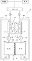
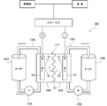
- FIG. 1 is a schematic diagram illustrating the configuration of the redox flow battery in the present embodiment.
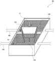
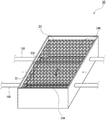
- FIG. 2 is a schematic diagram illustrating an example of an electrolytic solution tank of the redox flow battery illustrated in FIG. 1.
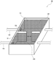
- FIG. 3 is a schematic diagram showing a modification of the partition wall of the electrolytic solution tank.
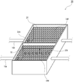
- FIG. 4 is a schematic view showing another modification of the partition wall of the electrolytic solution tank.
- FIG. 5 is a schematic view showing still another modified example of the partition walls of the electrolytic solution tank.
- FIG. 6 is a schematic diagram for explaining a conventional redox flow battery.
- FIG. 1 is a schematic diagram illustrating the configuration of the redox flow battery in the present embodiment.
- the redox flow battery 10 includes a battery cell 20 separated into a positive electrode cell 10A and a negative electrode cell 10B by a diaphragm 11 made of an ion exchange membrane, an electrolytic solution tank 30 for storing an electrolytic solution 31, Circulating pipes 16A and 16B that circulate and supply the electrolytic solution 31 from the electrolytic solution tank 30 to the battery cell 20 and circulating pumps 15A and 15B that are connected to the circulating pipes 16A and 16B and circulate the electrolytic solution 31 are provided.
- a positive electrode 12 is built in the positive cell 10A
- a negative electrode 13 is built in the negative cell 10B.
- the electrolytic solution tank 30 is separated by a partition wall 32 into a positive electrode electrolytic solution tank 34A and a negative electrode electrolytic solution tank 34B.
- the positive electrode electrolyte tank 34A is connected to the positive electrode cell 10A via the positive electrode electrolyte circulation pipe 16A
- the negative electrode electrolyte tank 34B is connected to the negative electrode cell 10B via the negative electrode electrolyte circulation pipe 16B.
- Circulation pipes 16A and 16B are provided with circulation pumps 15A and 15B, respectively, and the respective electrolytes are connected to the respective electrolyte tanks 34A and 34B via the positive electrode electrolyte circulation pipe 16A and the negative electrode electrolyte circulation pipe 16B. It is circulated between the cells 10A and 10B.
- the discharge port 16A1 and the suction port 16A2 of the positive electrode electrolyte tank 34A are arranged at positions as separated as possible in the positive electrode electrolyte tank 34A. Moreover, it is preferable to arrange
- an aqueous solution containing vanadium ions is used as the electrolytic solution 31, but is not particularly limited as long as the electrolytic solution contains ions of metal elements whose valence changes.
- the positive electrode electrolyte (electrolyte 31 supplied from the positive electrode electrolyte tank 34A to the positive electrode cell 10A) and the negative electrode electrolyte (electrolyte 31 supplied from the negative electrode electrolyte tank 34B to the negative electrode cell 10B) are as follows. , Ions of the same kind of metal element are included. It should be noted that the positive electrode electrolyte and the negative electrode electrolyte need only have the same species of elements contained as ions, and the ions and compounds do not necessarily have to be the same. Further, the positive electrode electrolyte and the negative electrode electrolyte become an electrolyte having the same composition from the time of rebalancing to the time of charging after mixing.
- the electrolyte bath 30 is preferably formed of a material having acid resistance, or the inside thereof is subjected to acid resistance treatment. From the viewpoint of manufacturing cost, the electrolytic solution tank 30 is preferably made of concrete subjected to acid resistance treatment.
- the partition wall 32 is formed of an acid-resistant material or the surface thereof is subjected to an acid resistance treatment.
- a material with high workability, light weight and high strength for example, fiber reinforced plastic (FRP). be able to.
- FRP fiber reinforced plastic
- a part of the partition wall 32 of the electrolytic solution tank 30 is configured to be openable and closable.
- the partition wall 32 is provided with an opening / closing part 32A, and the partition wall 32 is opened and closed by lifting and lowering the opening / closing part 32A by lifting means (not shown).
- the opening / closing part 32A When charging / discharging the redox flow battery 10, the opening / closing part 32A is lowered and the partition wall 32 is used in a closed state. On the other hand, when rebalancing is performed, the opening / closing part 32A is raised and the partition wall 32 is opened. Thereby, the electrolyte solution stored in the cathode electrolyte bath 34A and the electrolyte solution stored in the anode electrolyte bath 34B are mixed.
- the opening / closing part 32A is configured to be rotatable around a vertical axis by a rotating means (not shown).
- a rotating means not shown.
- the electrolytic solution 31 in the electrolytic solution tank 30 can be flowed by rotating the opening / closing part 32A, and rebalancing can be performed more quickly.
- the circulation pumps 15A and 15B provided in the circulation pipes 16A and 16B may be operated. Thereby, the electrolyte solution 31 staying in each of the cells 10A and 10B and the circulation pipes 16A and 16B can also be mixed, and rebalance can be performed more uniformly. Further, by operating the circulation pumps 15A and 15B, an effect of causing the electrolyte solution 31 in the electrolyte bath 30 to flow can be obtained.
- a stirring device using an impeller, a pump, or the like may be provided in the electrolytic solution tank 30, and the electrolytic solution 31 may be stirred by the stirring device.
- FIG. 3 is a schematic diagram showing a modification of the partition wall of the electrolytic solution tank.
- the opening / closing part 32A is configured to open and close in the horizontal direction, and the opening / closing part 32A is operated by a moving means (not shown).
- the circulation pumps 15A and 15B provided in the circulation pipes 16A and 16B are operated. It can.
- a stirring device using, for example, an impeller or a pump can be provided in the electrolytic solution tank 30.
- FIG. 4 is a schematic view showing another modification of the partition wall of the electrolytic solution tank.
- a hole 32B is provided in a part of the partition wall 32, and the opening / closing part 32A is moved up and down by lifting means (not shown), so that the opening and closing of the hole 32B, that is, the opening / closing part 32A can be opened and closed. .
- the circulation pumps 15A and 15B provided in the circulation pipes 16A and 16B are operated. It can.
- a stirring device using, for example, an impeller or a pump can be provided in the electrolytic solution tank 30.
- FIG. 5 is a schematic view showing still another modified example of the partition walls of the electrolytic solution tank.
- the entire partition wall 32 is configured as an opening / closing portion 32 ⁇ / b> A so as to be rotatable around a horizontal axis by a rotating means (not shown).
- the electrolytic solution 31 in the electrolytic solution tank 30 can be caused to flow and the electrolytic solution 31 can be stirred by rotating the opening / closing part 32A.
- the entire partition wall 32 is the opening / closing part 32A, but a part of the partition wall 32 may be the opening / closing part 32A.
- the electrolytic solution 31 in the electrolytic solution tank 30 may be caused to flow by operating the circulation pumps 15A and 15B provided in the circulation pipes 16A and 16B.
- a stirring device using, for example, an impeller or a pump can be provided in the electrolytic solution tank 30.
Landscapes
- Life Sciences & Earth Sciences (AREA)
- Engineering & Computer Science (AREA)
- Manufacturing & Machinery (AREA)
- Sustainable Development (AREA)
- Sustainable Energy (AREA)
- Chemical & Material Sciences (AREA)
- Chemical Kinetics & Catalysis (AREA)
- Electrochemistry (AREA)
- General Chemical & Material Sciences (AREA)
- Fuel Cell (AREA)
Abstract
La présente invention concerne une batterie à flux redox dans laquelle une solution électrolytique d'électrode positive et une solution électrolytique d'électrode négative peuvent être mélangées rapidement à des fins de rééquilibrage, et le mélange des solutions de rééquilibrage ne nécessite pas de tuyau de communication, de pompe ni d'autre équipement de ce type. Dans la présente invention, un réservoir de solution électrolytique pour stocker une solution électrolytique est divisé par une paroi de séparation en un réservoir de solution électrolytique positive relié à une cellule d'électrode positive d'un élément de batterie par l'intermédiaire d'un tuyau de circulation, et un réservoir de solution électrolytique négative relié à une cellule d'électrode négative de l'élément de batterie par l'intermédiaire du tuyau de circulation, la paroi de séparation étant conçue pour pouvoir être ouverte/fermée.
Priority Applications (1)
| Application Number | Priority Date | Filing Date | Title |
|---|---|---|---|
| JP2020516310A JP7216080B2 (ja) | 2018-04-24 | 2019-04-19 | レドックスフロー電池及びその運転方法 |
Applications Claiming Priority (2)
| Application Number | Priority Date | Filing Date | Title |
|---|---|---|---|
| JP2018-083035 | 2018-04-24 | ||
| JP2018083035 | 2018-04-24 |
Publications (1)
| Publication Number | Publication Date |
|---|---|
| WO2019208431A1 true WO2019208431A1 (fr) | 2019-10-31 |
Family
ID=68295305
Family Applications (1)
| Application Number | Title | Priority Date | Filing Date |
|---|---|---|---|
| PCT/JP2019/016816 Ceased WO2019208431A1 (fr) | 2018-04-24 | 2019-04-19 | Batterie à flux redox et son procédé de fonctionnement |
Country Status (2)
| Country | Link |
|---|---|
| JP (1) | JP7216080B2 (fr) |
| WO (1) | WO2019208431A1 (fr) |
Cited By (5)
| Publication number | Priority date | Publication date | Assignee | Title |
|---|---|---|---|---|
| CN114551934A (zh) * | 2020-11-24 | 2022-05-27 | 中国科学院大连化学物理研究所 | 一种液流电池电解液储罐及应用 |
| CN116031458A (zh) * | 2021-10-27 | 2023-04-28 | 中国科学院大连化学物理研究所 | 一种碱性锌铁液流电池或电堆运行策略 |
| CN116683004A (zh) * | 2023-06-25 | 2023-09-01 | 扬州西融储能科技有限公司 | 一种液流电池还原系统 |
| JP7599977B2 (ja) | 2021-02-02 | 2024-12-16 | 株式会社Ihiプラント | レドックスフロー電池 |
| WO2025126585A1 (fr) * | 2023-12-15 | 2025-06-19 | 住友電気工業株式会社 | Système de batterie à flux redox |
Citations (4)
| Publication number | Priority date | Publication date | Assignee | Title |
|---|---|---|---|---|
| JP2007188729A (ja) * | 2006-01-12 | 2007-07-26 | Sumitomo Electric Ind Ltd | バナジウムレドックスフロー電池の再生方法 |
| JP2012502445A (ja) * | 2009-10-29 | 2012-01-26 | ペキン プルーデント センチュリー テクノロジー カンパニーリミテッド | レドックスフロー電池及び長期間連続して電池を作動させる方法 |
| CN104143649A (zh) * | 2013-05-09 | 2014-11-12 | 中国科学院大连化学物理研究所 | 一种液流电池用一体化电解液储罐 |
| KR20150100040A (ko) * | 2014-02-24 | 2015-09-02 | 오씨아이 주식회사 | 레독스 흐름 전지 |
Family Cites Families (2)
| Publication number | Priority date | Publication date | Assignee | Title |
|---|---|---|---|---|
| JP2014137946A (ja) | 2013-01-18 | 2014-07-28 | Sumitomo Electric Ind Ltd | レドックスフロー電池の運転方法 |
| JP6414463B2 (ja) | 2014-12-22 | 2018-10-31 | 住友電気工業株式会社 | レドックスフロー電池の運転方法、及びレドックスフロー電池システム |
-
2019
- 2019-04-19 WO PCT/JP2019/016816 patent/WO2019208431A1/fr not_active Ceased
- 2019-04-19 JP JP2020516310A patent/JP7216080B2/ja active Active
Patent Citations (4)
| Publication number | Priority date | Publication date | Assignee | Title |
|---|---|---|---|---|
| JP2007188729A (ja) * | 2006-01-12 | 2007-07-26 | Sumitomo Electric Ind Ltd | バナジウムレドックスフロー電池の再生方法 |
| JP2012502445A (ja) * | 2009-10-29 | 2012-01-26 | ペキン プルーデント センチュリー テクノロジー カンパニーリミテッド | レドックスフロー電池及び長期間連続して電池を作動させる方法 |
| CN104143649A (zh) * | 2013-05-09 | 2014-11-12 | 中国科学院大连化学物理研究所 | 一种液流电池用一体化电解液储罐 |
| KR20150100040A (ko) * | 2014-02-24 | 2015-09-02 | 오씨아이 주식회사 | 레독스 흐름 전지 |
Cited By (6)
| Publication number | Priority date | Publication date | Assignee | Title |
|---|---|---|---|---|
| CN114551934A (zh) * | 2020-11-24 | 2022-05-27 | 中国科学院大连化学物理研究所 | 一种液流电池电解液储罐及应用 |
| CN114551934B (zh) * | 2020-11-24 | 2025-02-11 | 中国科学院大连化学物理研究所 | 一种液流电池电解液储罐及应用 |
| JP7599977B2 (ja) | 2021-02-02 | 2024-12-16 | 株式会社Ihiプラント | レドックスフロー電池 |
| CN116031458A (zh) * | 2021-10-27 | 2023-04-28 | 中国科学院大连化学物理研究所 | 一种碱性锌铁液流电池或电堆运行策略 |
| CN116683004A (zh) * | 2023-06-25 | 2023-09-01 | 扬州西融储能科技有限公司 | 一种液流电池还原系统 |
| WO2025126585A1 (fr) * | 2023-12-15 | 2025-06-19 | 住友電気工業株式会社 | Système de batterie à flux redox |
Also Published As
| Publication number | Publication date |
|---|---|
| JP7216080B2 (ja) | 2023-01-31 |
| JPWO2019208431A1 (ja) | 2021-05-13 |
Similar Documents
| Publication | Publication Date | Title |
|---|---|---|
| JP7216080B2 (ja) | レドックスフロー電池及びその運転方法 | |
| CN102859775B (zh) | 氧化还原液流电池及其运行方法 | |
| US9531028B2 (en) | Redox flow battery | |
| JP2012502445A (ja) | レドックスフロー電池及び長期間連続して電池を作動させる方法 | |
| CN107112567A (zh) | 使液流电池的电解液再生的组件和使用该组件使液流电池的电解液再生的方法 | |
| CN107112570A (zh) | 氧化还原液流电池的运行方法和氧化还原液流电池系统 | |
| JP7145883B2 (ja) | レドックスフロー電池及びその運転方法 | |
| JP2014137946A (ja) | レドックスフロー電池の運転方法 | |
| CN105680083B (zh) | 液流电池系统与液流电池系统的充放电方法 | |
| WO2020130014A1 (fr) | Batterie rédox, son procédé de fonctionnement et système de batterie rédox | |
| KR101942904B1 (ko) | 플로우 배터리에 적용 가능한 전해액 혼합 모듈 및 이를 이용한 플로우 배터리의 전해액 혼합 방법 | |
| KR102178304B1 (ko) | 밸런싱 유로를 사용하는 레독스 흐름전지 | |
| WO2020036107A1 (fr) | Solution électrolytique pour batteries redox, batterie redox et son procédé de fonctionnement | |
| JPWO2019078146A1 (ja) | 電解液、およびレドックスフロー電池 | |
| WO2020122183A1 (fr) | Batterie à flux redox et son procédé de fonctionnement | |
| KR20150138757A (ko) | 플로우 배터리에 적용 가능한 전해액 농도 조절 모듈 및 이를 이용한 플로우 배터리의 전해액 농도 균형 조절 방법 | |
| JP2006073471A (ja) | レドックスフロー電池及びその運転方法 | |
| WO2020130013A1 (fr) | Batterie à flux d'oxydoréduction et son procédé d'exploitation | |
| TW201931657A (zh) | 氧化還原液流電池及其運作方法 | |
| TW201931658A (zh) | 電解液及氧化還原液流電池 | |
| JP7518879B2 (ja) | 電力供給システム | |
| JP2026007506A (ja) | 電力供給装置 | |
| JPH0582034B2 (fr) |
Legal Events
| Date | Code | Title | Description |
|---|---|---|---|
| 121 | Ep: the epo has been informed by wipo that ep was designated in this application |
Ref document number: 19793459 Country of ref document: EP Kind code of ref document: A1 |
|
| ENP | Entry into the national phase |
Ref document number: 2020516310 Country of ref document: JP Kind code of ref document: A |
|
| NENP | Non-entry into the national phase |
Ref country code: DE |
|
| 122 | Ep: pct application non-entry in european phase |
Ref document number: 19793459 Country of ref document: EP Kind code of ref document: A1 |