WO2019208433A1 - Dispositif de surveillance rtp et procédé de surveillance rtp - Google Patents
Dispositif de surveillance rtp et procédé de surveillance rtp Download PDFInfo
- Publication number
- WO2019208433A1 WO2019208433A1 PCT/JP2019/016821 JP2019016821W WO2019208433A1 WO 2019208433 A1 WO2019208433 A1 WO 2019208433A1 JP 2019016821 W JP2019016821 W JP 2019016821W WO 2019208433 A1 WO2019208433 A1 WO 2019208433A1
- Authority
- WO
- WIPO (PCT)
- Prior art keywords
- packet
- terminal
- transmission packet
- called
- rtp
- Prior art date
- Legal status (The legal status is an assumption and is not a legal conclusion. Google has not performed a legal analysis and makes no representation as to the accuracy of the status listed.)
- Ceased
Links
Images

Classifications
-
- H—ELECTRICITY
- H04—ELECTRIC COMMUNICATION TECHNIQUE
- H04L—TRANSMISSION OF DIGITAL INFORMATION, e.g. TELEGRAPHIC COMMUNICATION
- H04L65/00—Network arrangements, protocols or services for supporting real-time applications in data packet communication
- H04L65/10—Architectures or entities
- H04L65/1016—IP multimedia subsystem [IMS]
-
- H—ELECTRICITY
- H04—ELECTRIC COMMUNICATION TECHNIQUE
- H04L—TRANSMISSION OF DIGITAL INFORMATION, e.g. TELEGRAPHIC COMMUNICATION
- H04L43/00—Arrangements for monitoring or testing data switching networks
- H04L43/08—Monitoring or testing based on specific metrics, e.g. QoS, energy consumption or environmental parameters
- H04L43/0805—Monitoring or testing based on specific metrics, e.g. QoS, energy consumption or environmental parameters by checking availability
- H04L43/0811—Monitoring or testing based on specific metrics, e.g. QoS, energy consumption or environmental parameters by checking availability by checking connectivity
-
- H—ELECTRICITY
- H04—ELECTRIC COMMUNICATION TECHNIQUE
- H04L—TRANSMISSION OF DIGITAL INFORMATION, e.g. TELEGRAPHIC COMMUNICATION
- H04L43/00—Arrangements for monitoring or testing data switching networks
- H04L43/10—Active monitoring, e.g. heartbeat, ping or trace-route
-
- H—ELECTRICITY
- H04—ELECTRIC COMMUNICATION TECHNIQUE
- H04L—TRANSMISSION OF DIGITAL INFORMATION, e.g. TELEGRAPHIC COMMUNICATION
- H04L43/00—Arrangements for monitoring or testing data switching networks
- H04L43/10—Active monitoring, e.g. heartbeat, ping or trace-route
- H04L43/106—Active monitoring, e.g. heartbeat, ping or trace-route using time related information in packets, e.g. by adding timestamps
-
- H—ELECTRICITY
- H04—ELECTRIC COMMUNICATION TECHNIQUE
- H04L—TRANSMISSION OF DIGITAL INFORMATION, e.g. TELEGRAPHIC COMMUNICATION
- H04L43/00—Arrangements for monitoring or testing data switching networks
- H04L43/18—Protocol analysers
-
- H—ELECTRICITY
- H04—ELECTRIC COMMUNICATION TECHNIQUE
- H04L—TRANSMISSION OF DIGITAL INFORMATION, e.g. TELEGRAPHIC COMMUNICATION
- H04L65/00—Network arrangements, protocols or services for supporting real-time applications in data packet communication
- H04L65/60—Network streaming of media packets
- H04L65/65—Network streaming protocols, e.g. real-time transport protocol [RTP] or real-time control protocol [RTCP]
-
- H—ELECTRICITY
- H04—ELECTRIC COMMUNICATION TECHNIQUE
- H04L—TRANSMISSION OF DIGITAL INFORMATION, e.g. TELEGRAPHIC COMMUNICATION
- H04L67/00—Network arrangements or protocols for supporting network services or applications
- H04L67/01—Protocols
- H04L67/10—Protocols in which an application is distributed across nodes in the network
-
- H—ELECTRICITY
- H04—ELECTRIC COMMUNICATION TECHNIQUE
- H04L—TRANSMISSION OF DIGITAL INFORMATION, e.g. TELEGRAPHIC COMMUNICATION
- H04L67/00—Network arrangements or protocols for supporting network services or applications
- H04L67/2866—Architectures; Arrangements
- H04L67/30—Profiles
- H04L67/303—Terminal profiles
-
- H—ELECTRICITY
- H04—ELECTRIC COMMUNICATION TECHNIQUE
- H04L—TRANSMISSION OF DIGITAL INFORMATION, e.g. TELEGRAPHIC COMMUNICATION
- H04L69/00—Network arrangements, protocols or services independent of the application payload and not provided for in the other groups of this subclass
- H04L69/28—Timers or timing mechanisms used in protocols
Definitions
- the present invention relates to an RTP monitoring apparatus and an RTP monitoring method for connecting a packet transfer network for transferring data using RTP (Real-time Transport Protocol).
- RTP Real-time Transport Protocol
- the operator operating the packet transfer network monitors the distribution status of voice and video packets (RTP packets) for each line from the viewpoint of ensuring communication quality and preventing erroneous charges, and distributes RTP packets for a certain period of time. When it is detected that there is no connection, the corresponding line may be disconnected. This function of disconnecting the line is hereinafter referred to as an RTP disconnection detection function.
- the line disconnection is performed based on the standards described in Non-Patent Documents 1 to 4.
- the RTP disconnection detection function monitors the time when RTP packets do not circulate with a timer, and acts to disconnect the line when the time when RTP packets do not circulate exceeds the timer time.
- the timer value for setting the timer time for determining the time until the line is disconnected is set according to the network policy based on the reliability of the network (network), and may be different for each network.
- the present invention has been made in view of this problem, and provides an RTP monitoring apparatus and an RTP monitoring method in which an RTP disconnection detection function operates appropriately even when networks having different timer values are interconnected. For the purpose.
- An RTP monitoring apparatus is an RTP monitoring apparatus that connects a packet transfer network, and includes a first timer that represents a predetermined time after a call-side transmission packet transmitted from a call-receiving terminal is interrupted.
- An RTP monitoring method is an RTP monitoring method executed by the above RTP monitoring apparatus, wherein a predetermined time after the incoming side transmission packet transmitted from the incoming side terminal is interrupted.
- the RTP disconnection detection function can be appropriately operated.
- FIG. 1 It is a block diagram which shows the structural example of the IP telephone network using the RTP monitoring apparatus which concerns on embodiment of this invention. It is a figure which shows the operation
- FIG. 1 is a block diagram showing a configuration example of an IP telephone network using an RTP monitoring apparatus according to an embodiment of the present invention.
- An IP telephone network 100 shown in FIG. 1 is a network that provides a telephone service using VoIP (Voice over Internet Protocol) technology.
- the IP telephone network 100 is a network that uses SIP (Session Initiation Protocol) as a path control protocol, and main information (data) communicated between terminals connected to the network is transmitted using RTP (Realtime Transport Protocol).
- SIP Session Initiation Protocol
- RTP Realtime Transport Protocol
- An IP telephone network 100 shown in FIG. 1 includes a calling side terminal 1, a packet transfer network 2, an RTP monitoring device 10, an SIP server 3, an SIP server 4, an RTP monitoring device 20, a packet transfer network 5, and a called side terminal 6.
- the packet transfer network 2 is a company A
- the packet transfer network 5 is a company B, for example.
- the policy may differ between operators operating the network. For example, when it is detected that an RTP packet is not distributed, the time (timer value) for operating the RTP disconnection detection function for disconnecting the corresponding line may be different.
- SIP servers 3 and 4 are servers that perform management control of IP telephone services using SIP, and are provided in each of the packet transfer networks 2 and 5.
- the RTP monitoring devices 10 and 20 are devices that enable communication of RTP packets of main information between adjacent networks, and also have an RTP disconnection detection function.
- the RTP monitoring devices 10 and 20 are generally referred to as SBC (Session Border Controller).
- the RTP monitoring devices 10 and 20 are the same, although the reference numbers are different.
- the RTP monitoring devices 10 and 20 may be integrated with separate SBCs or may be included in the SIP servers 3 and 4.
- the first timer value at which the RTP disconnection detection function of the packet transfer network 2 whose operating carrier is the company A operates is T1
- the RTP disconnection detection function of the packet transfer network 5 whose operating operator is the company B is Assume that the second timer value to operate is T2.
- T1 is a timer value such as 10 seconds
- T2 is 30 seconds.
- RTP disconnection detection is performed by either the RTP monitoring device 10 or the RTP monitoring device 20. Which is done depends on the agreement between the operators.
- the RTP monitoring apparatus 10 performs RTP disconnection detection will be described.
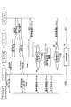
- FIG. 2 is an operation sequence diagram schematically showing an operation procedure of the IP telephone network 100.
- FIG. 2 only the incoming side interpolation packet generated when the incoming side transmission packet transmitted from the incoming side terminal 6 is interrupted for some reason for the convenience of drawing is shown.
- the calling side interpolation packet generated when the calling side transmission packet transmitted from the calling side terminal 1 is interrupted will be described later.
- the telephone numbers and IP addresses of the calling side terminal 1 and the called side terminal 6 are registered in the SIP servers 3 and 4 in advance. Alternatively, the telephone number and the IP address may be transmitted to the SIP servers 3 and 4 when each handset is picked up for the first time.
- the telephone number of the called side terminal 6 is dialed from the calling side terminal 1.
- an INVITE message is transmitted from the calling terminal 1 to the SIP server 3, and the SIP server 3 returns a provisional response of 100 Trying to the calling terminal 1.
- the provisional response of the INVITE message and 100 Trying is sequentially repeated between the SIP server 3 and the RTP monitoring device 10, the RTP monitoring device 10 and the SIP server 4, and the SIP server 4 and the called terminal 6.
- the called terminal 6 Upon receiving the INVITE message, the called terminal 6 transmits a 180Ringing provisional response to the calling terminal 1 (180Ringing). While receiving 180 Ringing, the calling terminal 1 can hear a ringing tone.
- the called terminal 6 When the handset of the called terminal 6 is lifted, the called terminal 6 transmits a 200OK success response to the calling terminal 1 (200OK).
- the calling terminal 1 transmits the ACK message directly to the called terminal 6 because it can know the IP address of the called terminal 6 when receiving 200OK.
- the transmission of the ACK message means that a line has been established (session established) between the calling terminal 1 and the called terminal 6. After the line is established, a voice packet, which is main information, is transmitted between the calling terminal 1 and the called terminal 6 using RTP. While the circuit is established, the SIP server 3, the RTP monitoring device 10, and the SIP server 4 monitor the distribution of RTP packets in the respective packet transfer networks 2 and 5.
- the called side transmission packet (voice packet) transmitted from the called side terminal 6 to the calling side terminal 1 is transmitted to the calling side terminal 1 (NO in step S1).
- a first monitoring timer (not shown) that counts the first timer value T1 provided in the RTP monitoring device 10 is reset every time the incoming call side transmission packet flows through the packet transfer network 2.
- the first timer value T1 is a timer value that measures the time during which the RTP disconnection detection function in the packet transfer network 2 operates.
- the SIP server 3 detects the disconnection of the line based on the first timer value T1, and transmits a BYE message indicating the disconnection of the line to the calling terminal 1 and the called terminal 6; Communication between both terminals ends.
- a called-side interpolation packet for interpolating the stopped called-side transmission packet is generated for a predetermined time after the first monitoring timer expires.
- the generated called side interpolation packet is transmitted to the SIP server 3 and the calling side terminal 1 (step S2).
- the time for which the called side interpolation packet is transmitted is from when the first monitoring timer expires (YES in step S1) until the second monitoring timer (second timer value T2) expires (YES in step S3). Is the time.
- the called side interpolation packet is transmitted to the SIP server 3 and the calling side terminal 1 for 10 to 30 seconds. Accordingly, the corresponding line of the packet transfer network 2 is not disconnected during that time. That is, since the callee side interpolation packet circulates in the packet transfer network 2 with a short timer value, disconnection of the line by the RTP disconnection detection function on the packet transfer network 2 side is suppressed.
- the RTP monitoring apparatus 10 presets timer values of the calling side network and the called side network, and performs interpolation packets (for example, called side interpolation packets) only for the difference between the timer values. Generate. As a result, the line can be disconnected based on the larger timer value.
- first timer value T1 is smaller than the second timer value T2
- first timer value T1 may be larger than the second timer value T2.
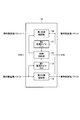
- FIG. 3 is a block diagram illustrating a functional configuration example of the RTP monitoring apparatus 10.
- notations such as a communication interface unit, a control unit, and a SIP message analysis unit, which are general configurations, are omitted.
- the RTP monitoring apparatus 10 includes a first monitoring timer 11, a second monitoring timer 12, a line disconnection unit 13, a first relay interpolation unit 14, and a second relay interpolation unit 15.
- Each functional component of the RTP monitoring apparatus 10 is realized by a computer including a ROM, a RAM, a CPU, and the like, for example.
- the processing content of the function that each functional component should have is described by a program.
- the line disconnecting unit 13 is not an indispensable functional component. The reason will be described later.
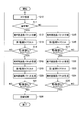
- FIG. 4 is a flowchart showing a processing procedure of the RTP monitoring apparatus 10.
- FIG. 4 shows a processing procedure after a line is established between the calling terminal 1 and the called terminal 6.
- FIG. 4 shows a call-side transmission packet and a call-side transmission packet received by the control unit of the RTP monitoring apparatus 10 (not shown) from the call-side terminal 6 and the call-side terminal 1, respectively. It is a flowchart shown in the example allocated to the 1st relay interpolation part 14 and the 2nd relay interpolation part 15, respectively.
- the first relay interpolation unit 14 relays the received called side transmission packet to the calling side terminal 1 (step S12).
- the first monitoring timer 11 is reset by the received incoming call transmission packet (step S13). The reset of the first monitoring timer 11 is repeatedly performed every time the incoming call side transmission packet is received.
- the first monitoring timer 11 does not time out unless the incoming side transmission packet transmitted from the incoming side terminal 6 is interrupted for the first timer value T1 or more. It is assumed that for some reason, the incoming side transmission packet transmitted from the incoming side terminal 6 is interrupted, and the outgoing side transmission packet transmitted from the outgoing side terminal 1 is continuously received.
- the second relay interpolation unit 15 relays the received calling side transmission packet to the called side terminal 6 (step S18). And the 2nd monitoring timer 12 is reset with the received calling side transmission packet (step S19).
- the control unit causes the first relay interpolating unit 14 to generate a called side interpolation packet for interpolating the interrupted called side transmission packet, and the generated called side interpolation packet to the calling side. A command to be transmitted to the terminal 1 is issued.
- the interrupted called side transmission packet is interpolated by the called side interpolation packet generated by the first relay interpolation unit 14 (step S20).
- the generation and interpolation of the called side interpolation packet are repeated until the second timer value T2 timed by the second monitoring timer 12 is finished (NO loop in step S21).
- the first timer value T1 and the second timer value T2 are stored in advance in, for example, a ROM or the like that constitutes the RTP monitoring apparatus 10.
- the line disconnecting unit 13 When the second monitoring timer 12 finishes counting the second timer value T2 after reception of the calling side transmission packet from the calling side terminal 1 is interrupted (YES in step S21), the line disconnecting unit 13 has already Since the time count of the first timer value T1 is also up, a BYE message indicating line disconnection is transmitted to each of the calling terminal 1 and the called terminal 6 to notify the disconnection of the line (step S26). ). Note that the SIP server 3 may be notified of line disconnection. That is, since the RTP disconnection detection function may be provided in the SIP servers 3 and 4, the BYE message may be transmitted using the functions of the SIP servers 3 and 4. In this case, the line disconnecting unit 13 of the RTP monitoring apparatus 10 is not necessary.
- the second relay interpolation unit 15 relays the received calling side transmission packet to the called side terminal 6 (Step S15).
- the second monitoring timer 12 is reset by the received calling side transmission packet (step S16). The reset of the second monitoring timer 11 is repeatedly performed every time the calling side transmission packet is received.
- the second monitoring timer 12 does not time up unless the calling side transmission packet transmitted from the calling side terminal 1 is interrupted for the second timer value T2 or more. For some reason, it is assumed that the calling side transmission packet transmitted from the calling side terminal 1 is interrupted, and the called side transmission packet transmitted from the called side terminal 6 is continuously received.
- the first relay interpolation unit 14 relays the received call-side transmission packet to the call-side terminal 1 (step S22). And the 1st monitoring timer 11 is reset with the received callee side transmission packet (step S23).
- the control unit causes the second relay interpolation unit 15 to generate a calling side interpolation packet for interpolating the disconnected calling side transmission packet, and the generated calling side interpolation packet to the called side. A command to be transmitted to the terminal 6 is issued.
- the interrupted calling side transmission packet is interpolated by the calling side interpolation packet generated by the second relay interpolation unit 15 (step S24).
- the generation and interpolation of the calling side interpolation packet are repeated until the time measurement of the first timer value T2 timed by the first monitoring timer 11 is completed (NO loop of step S25).
- the line disconnecting unit 13 When the first monitoring timer 11 finishes counting the first timer value T1 after reception of the calling side transmission packet from the calling side terminal 1 is interrupted (YES in step S25), the line disconnecting unit 13 has already Since the time count of the second timer value T2 is also up, a BYE message indicating line disconnection is transmitted to each of the calling terminal 1 and the called terminal 6 to notify the disconnection of the line (step S26). ).
- the RTP monitoring apparatus 10 performs the first monitoring that measures the first timer value T1 that represents a predetermined time after the incoming side transmission packet transmitted from the incoming side terminal 6 stops.
- a timer 11, a second monitoring timer 12 that counts a second timer value T2 indicating a predetermined time after the calling side transmission packet transmitted from the calling side terminal 1 is interrupted, and a called side transmission packet is called.
- the caller side When the first monitoring timer 11 is timed up and the second monitoring timer 12 is timing, the caller side generates a callee side interpolation packet for interpolating the callee side transmission packet.
- the second monitoring timer 12 is timed up, and the first monitoring timer 11 is measuring time , Caller send packet
- the second relay interpolation unit 15 that generates and transmits the calling side interpolation packet to be transmitted to the called side terminal 6 and the first monitoring timer 11 and the second monitoring timer 12 have timed out, the calling side terminal 1 And a line disconnecting unit 13 for notifying both of the called terminal 6 of the disconnection of the line.
- an interpolation packet (calling side interpolation packet, called side interpolation packet) is transmitted and interpolated toward a network with a short timer value (packet transfer network), so that the RTP disconnection detection function of the network with a small timer value can be realized.
- the operation is suppressed, and the RTP break detection function of the network having a large timer value operates.
- the RTP disconnection detection function can be appropriately operated even when networks having different timer values are connected. That is, it is possible to continue using the RTP disconnection detection function among all the operators while maintaining the policy of each network without affecting the existing facilities and devices.
- the timing processing of the first monitoring timer 11 and the second monitoring timer 12 is performed independently. Accordingly, the magnitudes of the first timer value T1 and the second timer value T2 may be such that the first timer value T1 is smaller than the second timer value T2, and the first timer value T1 is smaller than the second timer value T2. It can be large.
- the called side interpolation packet and the calling side interpolation packet generated by the first relay interpolation unit 14 and the second relay interpolation unit 15 are, for example, silent packets if they are voice packets. If a silent packet is transmitted over several tens of seconds, the user may feel anxious about an unexplained failure.
- each of the called side interpolation packet and the calling side interpolation packet may have a meaning.
- a call-side interpolation packet and a call-side interpolation packet may be used for transmission of voice guidance such as “communication is unstable”.
- Information such as “communication is unstable” may be transmitted as text information.
- the first relay interpolation unit 14 transmits information indicating that the packet is a packet for interpolating the incoming side transmission packet to the incoming side interpolation packet and transmits it to the calling side terminal 1, and the second relay interpolation unit 15. Transmits information indicating that the packet is a packet for interpolating the calling side transmission packet to the calling side interpolation packet and transmits it to the called side terminal 6. Thereby, since the user can grasp the situation, the user does not feel uneasy.
- first timer value T1 and the second timer value T2 have been described as being stored in advance in, for example, a ROM or the like constituting the RTP monitoring apparatus 10, but the present invention is not limited to this example.
- the first timer value T1 and the second timer value T2 may be described in the SIP message.
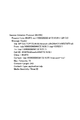
- FIG. 5 shows a specific example of the SIP INVITE message.
- the timer value of 30 seconds is described in the bottom line of FIG.
- the first timer value T1 and the second timer value T2 may be described in the INVITE message, and the description may be analyzed by the SIP message analysis unit (not shown) and held in the RAM or the like. .
- the second relay interpolation unit 15 refers to the state of the line disconnection unit 13 (a control line connecting the line disconnection unit 13 and the second relay interpolation unit 15 (FIG. 3)), and performs call-side interpolation according to the state.
- a packet may be generated.
- the second relay interpolation unit 15 generates a call-side interpolation packet while the first monitoring timer 11 times out and the second monitoring timer 12 measures time. The same applies to the calling side interpolation packet.
- the present invention is not limited to the above embodiment, and can be modified within the scope of the gist thereof.
Landscapes
- Engineering & Computer Science (AREA)
- Computer Networks & Wireless Communication (AREA)
- Signal Processing (AREA)
- Multimedia (AREA)
- Health & Medical Sciences (AREA)
- Cardiology (AREA)
- General Health & Medical Sciences (AREA)
- Environmental & Geological Engineering (AREA)
- Computer Security & Cryptography (AREA)
- Data Exchanges In Wide-Area Networks (AREA)
- Telephonic Communication Services (AREA)
- Business, Economics & Management (AREA)
- General Business, Economics & Management (AREA)
Abstract
Le but de la présente invention est de permettre à une fonction de détection d'interruption RTP de fonctionner correctement même lorsque des réseaux comportant différentes valeurs de temporisateur sont connectés l'un à l'autre. Le dispositif de surveillance RTP est pourvu : d'un premier temporisateur de surveillance 11 pour compter une première valeur de temporisateur indiquant une durée prédéterminée après qu'un paquet de transmission côté appelé transmis à partir d'un terminal côté appelé 6 est interrompu ; d'un second temporisateur de surveillance 12 pour compter une seconde valeur de temporisateur indiquant une durée prédéterminée après l'interruption d'un paquet de transmission côté appelant transmis à partir d'un terminal côté appelant 1 ; d'une première unité de relais/interpolation 14 pour relayer le paquet de transmission côté appelé au terminal côté appelant 1, et pour générer et transmettre un paquet d'interpolation côté appelé pour interpoler le paquet de transmission côté appelé au terminal côté appelant 1 lorsque le temps de comptage du premier temporisateur de surveillance 11 a expiré et que le second temporisateur de surveillance 12 est encore en train de compter ; et d'une seconde unité de relais/interpolation 15 pour relayer le paquet de transmission côté appelant au terminal côté appelé 6, et pour générer et transmettre un paquet d'interpolation côté appelant pour interpoler le paquet de transmission côté appelant au terminal côté appelé 6 lorsque le temps de comptage du second temporisateur de surveillance 12 a expiré et que le premier temporisateur de surveillance 11 est toujours en train de compter.
Priority Applications (1)
| Application Number | Priority Date | Filing Date | Title |
|---|---|---|---|
| US17/048,883 US11102268B2 (en) | 2018-04-24 | 2019-04-19 | RTP monitoring device and RTP monitoring method |
Applications Claiming Priority (2)
| Application Number | Priority Date | Filing Date | Title |
|---|---|---|---|
| JP2018-082816 | 2018-04-24 | ||
| JP2018082816A JP6955170B2 (ja) | 2018-04-24 | 2018-04-24 | Rtp監視装置及びrtp監視方法 |
Publications (1)
| Publication Number | Publication Date |
|---|---|
| WO2019208433A1 true WO2019208433A1 (fr) | 2019-10-31 |
Family
ID=68295422
Family Applications (1)
| Application Number | Title | Priority Date | Filing Date |
|---|---|---|---|
| PCT/JP2019/016821 Ceased WO2019208433A1 (fr) | 2018-04-24 | 2019-04-19 | Dispositif de surveillance rtp et procédé de surveillance rtp |
Country Status (3)
| Country | Link |
|---|---|
| US (1) | US11102268B2 (fr) |
| JP (1) | JP6955170B2 (fr) |
| WO (1) | WO2019208433A1 (fr) |
Citations (3)
| Publication number | Priority date | Publication date | Assignee | Title |
|---|---|---|---|---|
| JP2003124967A (ja) * | 2001-10-15 | 2003-04-25 | Hitachi Communication Technologies Ltd | 中継装置、その制御プログラム、通信方法 |
| JP2003244238A (ja) * | 2002-02-15 | 2003-08-29 | Kddi Corp | トラヒック監視装置及びその方法、コンピュータプログラム |
| US20160373585A1 (en) * | 2015-06-16 | 2016-12-22 | Apple Inc. | Managing Packet-Switched Voice Communications during Silence Intervals |
Family Cites Families (6)
| Publication number | Priority date | Publication date | Assignee | Title |
|---|---|---|---|---|
| JPS60197055A (ja) * | 1984-03-21 | 1985-10-05 | Hashimoto Corp | 信号の識別処理手段を有する留守番電話装置 |
| US6115776A (en) * | 1996-12-05 | 2000-09-05 | 3Com Corporation | Network and adaptor with time-based and packet number based interrupt combinations |
| US7953841B2 (en) * | 2002-08-22 | 2011-05-31 | Jds Uniphase Corporation | Monitoring an RTP data stream based on a phone call |
| GB0604537D0 (en) * | 2006-03-07 | 2006-04-12 | Ghost Telecom Ltd | Method and apparatus of interfacing and connecting a wireless device(s) and specific application server(s) for location update(s), in-and out-going call(s)... |
| JP2015226141A (ja) * | 2014-05-27 | 2015-12-14 | Necエンジニアリング株式会社 | 中継装置、回線交換システム及び回線交換方法 |
| US20160261502A1 (en) * | 2015-03-02 | 2016-09-08 | Lookingglass Cyber Solutions, Inc. | Detection and mitigation of network component distress |
-
2018
- 2018-04-24 JP JP2018082816A patent/JP6955170B2/ja active Active
-
2019
- 2019-04-19 US US17/048,883 patent/US11102268B2/en active Active
- 2019-04-19 WO PCT/JP2019/016821 patent/WO2019208433A1/fr not_active Ceased
Patent Citations (3)
| Publication number | Priority date | Publication date | Assignee | Title |
|---|---|---|---|---|
| JP2003124967A (ja) * | 2001-10-15 | 2003-04-25 | Hitachi Communication Technologies Ltd | 中継装置、その制御プログラム、通信方法 |
| JP2003244238A (ja) * | 2002-02-15 | 2003-08-29 | Kddi Corp | トラヒック監視装置及びその方法、コンピュータプログラム |
| US20160373585A1 (en) * | 2015-06-16 | 2016-12-22 | Apple Inc. | Managing Packet-Switched Voice Communications during Silence Intervals |
Also Published As
| Publication number | Publication date |
|---|---|
| JP6955170B2 (ja) | 2021-10-27 |
| US11102268B2 (en) | 2021-08-24 |
| JP2019193055A (ja) | 2019-10-31 |
| US20210168189A1 (en) | 2021-06-03 |
Similar Documents
| Publication | Publication Date | Title |
|---|---|---|
| EP1911229B1 (fr) | Association d'un appel téléphonique à un dialogue sur la base d'un protocole d'ordinateur tel que sip | |
| KR20130121183A (ko) | Sip를 이용하는 기업 네트워크의 생존성을 위한 백업 sip 서버 | |
| US9729585B2 (en) | Communications adaptor for use with internet telephony system | |
| CN102137198B (zh) | 总机业务的实现方法及网关设备 | |
| US9071690B2 (en) | Call transfer processing in SIP mode | |
| EP2020813B1 (fr) | Procédé, dispositif et système pour mettre en oeuvre le service de session | |
| US9258367B2 (en) | Technique for managing sessions with entities in a communication network | |
| EP2200254B1 (fr) | Système de réseau mobile et procédé de fourniture de message de guidage | |
| WO2009036801A1 (fr) | Procédés et agencements pour un système de télécommunications | |
| WO2019208433A1 (fr) | Dispositif de surveillance rtp et procédé de surveillance rtp | |
| JP2005020676A (ja) | 電話通信方法及び装置 | |
| CN103475648B (zh) | 基于sip协议的呼叫盲转方法及呼叫盲转系统 | |
| US20080137647A1 (en) | VoIP terminal and method for providing multi-call service | |
| EP2289253B1 (fr) | Procédé d'obtention d'une fonctionnalité de mise en attente d'appel dans un réseau de communication | |
| KR100907612B1 (ko) | 아이피 멀티미디어 서브시스템에서 세션 종료 후의 과금처리 방법 및 시스템 | |
| KR100475187B1 (ko) | 접속 설정 프로토콜 방식을 지원하는 키폰 시스템 및 그호 설정 방법 | |
| JP4136798B2 (ja) | 音声ガイダンス機能付き中継装置 | |
| JP5248891B2 (ja) | Sipを用いたボタン電話装置による会議招集方法、そのシステム、その装置及びそのプログラム | |
| US20090103519A1 (en) | Method and Computer Product for Switching Subsequent Messages With Higher Priority Than Invite Messages in a Softswitch | |
| US20080198992A1 (en) | Method for Setting Up a Multimedia Connection In Case Of Cascade Connection Transfer | |
| JP5359710B2 (ja) | 通信システム、通信装置、及び通信システムにおける通信方法 | |
| JP2009218889A (ja) | Sip着信方法 | |
| Herceg et al. | Challenges in Implementing a SIP-Based Application Server | |
| KR20070063788A (ko) | VoIP 서비스를 제공하는 액세스 게이트웨이 및 그 방법 |
Legal Events
| Date | Code | Title | Description |
|---|---|---|---|
| 121 | Ep: the epo has been informed by wipo that ep was designated in this application |
Ref document number: 19793634 Country of ref document: EP Kind code of ref document: A1 |
|
| NENP | Non-entry into the national phase |
Ref country code: DE |
|
| 122 | Ep: pct application non-entry in european phase |
Ref document number: 19793634 Country of ref document: EP Kind code of ref document: A1 |