WO2019211995A1 - Dispositif de commande pour moteur de type à allumage par compression - Google Patents
Dispositif de commande pour moteur de type à allumage par compression Download PDFInfo
- Publication number
- WO2019211995A1 WO2019211995A1 PCT/JP2019/016876 JP2019016876W WO2019211995A1 WO 2019211995 A1 WO2019211995 A1 WO 2019211995A1 JP 2019016876 W JP2019016876 W JP 2019016876W WO 2019211995 A1 WO2019211995 A1 WO 2019211995A1
- Authority
- WO
- WIPO (PCT)
- Prior art keywords
- ignition
- combustion
- fuel
- injection
- engine
- Prior art date
- Legal status (The legal status is an assumption and is not a legal conclusion. Google has not performed a legal analysis and makes no representation as to the accuracy of the status listed.)
- Ceased
Links
Images


Classifications
-
- F—MECHANICAL ENGINEERING; LIGHTING; HEATING; WEAPONS; BLASTING
- F02—COMBUSTION ENGINES; HOT-GAS OR COMBUSTION-PRODUCT ENGINE PLANTS
- F02P—IGNITION, OTHER THAN COMPRESSION IGNITION, FOR INTERNAL-COMBUSTION ENGINES; TESTING OF IGNITION TIMING IN COMPRESSION-IGNITION ENGINES
- F02P15/00—Electric spark ignition having characteristics not provided for in, or of interest apart from, groups F02P1/00 - F02P13/00 and combined with layout of ignition circuits
- F02P15/08—Electric spark ignition having characteristics not provided for in, or of interest apart from, groups F02P1/00 - F02P13/00 and combined with layout of ignition circuits having multiple-spark ignition, i.e. ignition occurring simultaneously at different places in one engine cylinder or in two or more separate engine cylinders
-
- F—MECHANICAL ENGINEERING; LIGHTING; HEATING; WEAPONS; BLASTING
- F02—COMBUSTION ENGINES; HOT-GAS OR COMBUSTION-PRODUCT ENGINE PLANTS
- F02D—CONTROLLING COMBUSTION ENGINES
- F02D41/00—Electrical control of supply of combustible mixture or its constituents
- F02D41/30—Controlling fuel injection
- F02D41/3011—Controlling fuel injection according to or using specific or several modes of combustion
- F02D41/3017—Controlling fuel injection according to or using specific or several modes of combustion characterised by the mode(s) being used
- F02D41/3035—Controlling fuel injection according to or using specific or several modes of combustion characterised by the mode(s) being used a mode being the premixed charge compression-ignition mode
- F02D41/3041—Controlling fuel injection according to or using specific or several modes of combustion characterised by the mode(s) being used a mode being the premixed charge compression-ignition mode with means for triggering compression ignition, e.g. spark plug
-
- F—MECHANICAL ENGINEERING; LIGHTING; HEATING; WEAPONS; BLASTING
- F02—COMBUSTION ENGINES; HOT-GAS OR COMBUSTION-PRODUCT ENGINE PLANTS
- F02B—INTERNAL-COMBUSTION PISTON ENGINES; COMBUSTION ENGINES IN GENERAL
- F02B23/00—Other engines characterised by special shape or construction of combustion chambers to improve operation
- F02B23/02—Other engines characterised by special shape or construction of combustion chambers to improve operation with compression ignition
-
- F—MECHANICAL ENGINEERING; LIGHTING; HEATING; WEAPONS; BLASTING
- F02—COMBUSTION ENGINES; HOT-GAS OR COMBUSTION-PRODUCT ENGINE PLANTS
- F02B—INTERNAL-COMBUSTION PISTON ENGINES; COMBUSTION ENGINES IN GENERAL
- F02B23/00—Other engines characterised by special shape or construction of combustion chambers to improve operation
- F02B23/08—Other engines characterised by special shape or construction of combustion chambers to improve operation with positive ignition
- F02B23/10—Other engines characterised by special shape or construction of combustion chambers to improve operation with positive ignition with separate admission of air and fuel into cylinder
-
- F—MECHANICAL ENGINEERING; LIGHTING; HEATING; WEAPONS; BLASTING
- F02—COMBUSTION ENGINES; HOT-GAS OR COMBUSTION-PRODUCT ENGINE PLANTS
- F02B—INTERNAL-COMBUSTION PISTON ENGINES; COMBUSTION ENGINES IN GENERAL
- F02B31/00—Modifying induction systems for imparting a rotation to the charge in the cylinder
- F02B31/08—Modifying induction systems for imparting a rotation to the charge in the cylinder having multiple air inlets
- F02B31/085—Modifying induction systems for imparting a rotation to the charge in the cylinder having multiple air inlets having two inlet valves
-
- F—MECHANICAL ENGINEERING; LIGHTING; HEATING; WEAPONS; BLASTING
- F02—COMBUSTION ENGINES; HOT-GAS OR COMBUSTION-PRODUCT ENGINE PLANTS
- F02D—CONTROLLING COMBUSTION ENGINES
- F02D41/00—Electrical control of supply of combustible mixture or its constituents
- F02D41/30—Controlling fuel injection
- F02D41/38—Controlling fuel injection of the high pressure type
- F02D41/40—Controlling fuel injection of the high pressure type with means for controlling injection timing or duration
- F02D41/402—Multiple injections
-
- F—MECHANICAL ENGINEERING; LIGHTING; HEATING; WEAPONS; BLASTING
- F02—COMBUSTION ENGINES; HOT-GAS OR COMBUSTION-PRODUCT ENGINE PLANTS
- F02D—CONTROLLING COMBUSTION ENGINES
- F02D41/00—Electrical control of supply of combustible mixture or its constituents
- F02D41/0002—Controlling intake air
- F02D2041/0015—Controlling intake air for engines with means for controlling swirl or tumble flow, e.g. by using swirl valves
-
- F—MECHANICAL ENGINEERING; LIGHTING; HEATING; WEAPONS; BLASTING
- F02—COMBUSTION ENGINES; HOT-GAS OR COMBUSTION-PRODUCT ENGINE PLANTS
- F02D—CONTROLLING COMBUSTION ENGINES
- F02D45/00—Electrical control not provided for in groups F02D41/00 - F02D43/00
-
- Y—GENERAL TAGGING OF NEW TECHNOLOGICAL DEVELOPMENTS; GENERAL TAGGING OF CROSS-SECTIONAL TECHNOLOGIES SPANNING OVER SEVERAL SECTIONS OF THE IPC; TECHNICAL SUBJECTS COVERED BY FORMER USPC CROSS-REFERENCE ART COLLECTIONS [XRACs] AND DIGESTS
- Y02—TECHNOLOGIES OR APPLICATIONS FOR MITIGATION OR ADAPTATION AGAINST CLIMATE CHANGE
- Y02T—CLIMATE CHANGE MITIGATION TECHNOLOGIES RELATED TO TRANSPORTATION
- Y02T10/00—Road transport of goods or passengers
- Y02T10/10—Internal combustion engine [ICE] based vehicles
- Y02T10/12—Improving ICE efficiencies
-
- Y—GENERAL TAGGING OF NEW TECHNOLOGICAL DEVELOPMENTS; GENERAL TAGGING OF CROSS-SECTIONAL TECHNOLOGIES SPANNING OVER SEVERAL SECTIONS OF THE IPC; TECHNICAL SUBJECTS COVERED BY FORMER USPC CROSS-REFERENCE ART COLLECTIONS [XRACs] AND DIGESTS
- Y02—TECHNOLOGIES OR APPLICATIONS FOR MITIGATION OR ADAPTATION AGAINST CLIMATE CHANGE
- Y02T—CLIMATE CHANGE MITIGATION TECHNOLOGIES RELATED TO TRANSPORTATION
- Y02T10/00—Road transport of goods or passengers
- Y02T10/10—Internal combustion engine [ICE] based vehicles
- Y02T10/40—Engine management systems
Definitions
- the present invention relates to a control device for a compression ignition engine capable of partial compression ignition combustion in which a part of an air-fuel mixture is subjected to SI combustion by spark ignition and another air-fuel mixture is subjected to CI combustion by self-ignition.
- HCCI combustion is a mode in which the air-fuel mixture burns at the same time. Therefore, compared to SI combustion (spark ignition combustion) used in ordinary gasoline engines, the air-fuel mixture burns faster and is extremely heat efficient. It is said that it is advantageous to.
- SI combustion spark ignition combustion
- HCCI combustion has a problem that the combustion start timing of the air-fuel mixture (the time when the air-fuel mixture self-ignites) fluctuates greatly due to external factors such as temperature, and control during transient operation where the load changes suddenly. There was also a problem that was difficult.
- Patent Document 1 An engine employing a concept similar to the partial compression ignition combustion is disclosed in Patent Document 1.
- a stratified mixture formed around an ignition plug (ignition plug) by auxiliary fuel injection is subjected to flame propagation combustion by spark ignition.
- the main fuel is injected into the combustion chamber heated to a high temperature by the action of the combustion (flame), and the fuel injected by the main fuel injection is burned by self-ignition.
- Patent Document 2 discloses a spark ignition engine in which spark ignition by a spark plug is executed twice in one cycle.
- pre-ignition is performed during the compression stroke to supply ignition energy that is small enough that the entire air-fuel mixture in the combustion chamber is not ignited and burned (so that a local kind of fire is formed).
- Main ignition that supplies ignition energy larger than the preceding ignition is executed at an appropriate timing delayed from the preceding ignition.
- the combustion rate of CI combustion affects the thermal efficiency. Since CI combustion is a phenomenon in which fuel components spontaneously react chemically, it can be said that the combustion rate is inherently faster than SI combustion in which the combustion region gradually expands due to flame propagation. However, for example, if the fuel can be reformed to a highly reactive one before the CI combustion, the combustion speed of the CI combustion can be further increased, the thermal efficiency can be further improved, and both fuel efficiency performance and torque performance can be achieved. It is considered possible.
- the fuel reforming to increase the reactivity may be realized by raising the temperature of the air-fuel mixture to a predetermined temperature range, for example. That is, an intermediate product containing highly reactive OH radicals is generated by cleaving the fuel component (hydrocarbon) by raising the temperature of the air-fuel mixture.
- the inventor of the present application performs, for example, spark ignition a plurality of times as in the case of Patent Document 2, that is, rather than the main ignition. We considered increasing the temperature of the air-fuel mixture by performing an auxiliary pre-ignition before.
- JP 2009-108778 A Japanese Patent No. 4691373
- An object of the present invention is to provide a control device for a compression ignition type engine capable of realizing partial compression ignition combustion having a high combustion rate and excellent thermal efficiency.
- a control apparatus for a compression ignition engine includes a cylinder, an injector that injects fuel into the cylinder, and an ignition plug that ignites an air-fuel mixture in which fuel and air injected from the injector are mixed. And a compression ignition engine capable of partial compression ignition combustion in which a part of the air-fuel mixture is subjected to SI combustion by spark ignition of the spark plug and other air-fuel mixture is subjected to CI combustion by self-ignition.
- the said control apparatus is provided with the injection control part which controls the injection operation of the fuel by the said injector, and the ignition control part which controls the ignition operation by the said ignition plug.
- the ignition control unit causes the ignition plug to execute main ignition that generates a spark and starts SI combustion and pre-ignition that generates a spark earlier than the main ignition when the partial compression ignition combustion is performed. .
- the said injection control part performs fuel injection in an intake stroke.
- the ignition control unit sets the energy of the preceding ignition to be smaller than the energy of the main ignition, and executes the preceding ignition after the fuel injection in the intake stroke, or in the first or middle period of the compression stroke.
- a control device for a compression ignition engine is an apparatus for controlling an engine including a cylinder, an injector and a spark plug disposed so as to face the cylinder, the injector and the A controller electrically connected to the spark plug and outputting a control signal to the injector and the spark plug;
- the controller has an electric circuit.
- the controller having the electric circuit is a partial compression ignition in which a mixture of fuel and air injected from the injector is subjected to flame propagation combustion by spark ignition by the ignition plug, and compression self-ignition combustion occurs after the start of the flame propagation combustion.
- a combustion control unit that executes combustion, an injection control unit that drives the injector when performing the partial compression ignition combustion, and injects fuel during an intake stroke; and a spark that is generated when the partial compression ignition combustion is performed
- a first ignition control unit for performing main ignition for starting the flame propagation combustion, and performing pre-ignition for generating a spark at an earlier time than the main ignition when performing the partial compression ignition combustion,
- the energy of the pre-ignition is set smaller than the energy of the main ignition, and the pre-ignition is used for the fuel injection in the intake stroke.
- FIG. 1 is a system diagram schematically showing an overall configuration of a compression ignition engine according to an embodiment of the present invention.
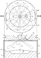
- FIG. 2 is a view showing both a sectional view of the engine body and a plan view of the piston.
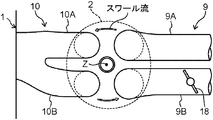
- FIG. 3 is a schematic plan view showing the structure of the intake and exhaust system in the vicinity of the cylinder.
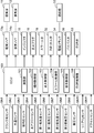
- FIG. 4 is a block diagram showing an engine control system.
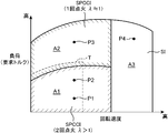
- FIG. 5 is an operation map in which the operation region of the engine is divided according to the difference in combustion mode.
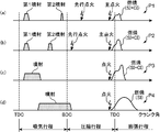
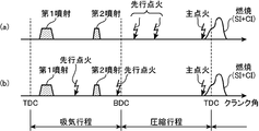
- FIG. 6 is a time chart for schematically explaining the combustion control performed in each operation region of the engine.
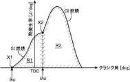
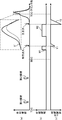
- FIG. 7 is a graph showing the waveform of the heat generation rate during SPCCI combustion (partial compression ignition combustion).
- FIG. 8 is a map diagram showing a specific example of the target air-fuel ratio set in the first operating region of the engine.
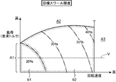
- FIG. 9 is a map diagram showing a specific example of the target swirl opening degree set in the first operation region.
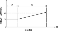
- FIG. 10 is a graph showing changes in the target swirl opening when the rotational speed is changed under a constant load condition.
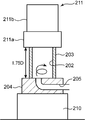
- FIG. 11 is a diagram showing an outline of a rig testing apparatus for measuring a swirl ratio.
- FIG. 12 is a graph showing the relationship between the swirl opening degree and the swirl ratio.
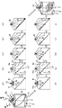
- FIG. 13 is an explanatory diagram showing the behavior of fuel (spray) injected from the injector in relation to the swirl flow.
- FIGS. 14A to 14E are views schematically showing the air-fuel mixture moving with the swirl flow as viewed from above the combustion chamber.
- FIG. 14A to 14E are views schematically showing the air-fuel mixture moving with the swirl flow as viewed from above the combustion chamber.
- FIG. 14A to 14E are views schematically showing the air-
- FIG. 15 is a flowchart showing a specific example of combustion control when the engine is warm.
- FIG. 16 is a subroutine showing details of control in step S10 of FIG.
- FIGS. 17A and 17B are map diagrams for determining basic ignition energy of preceding ignition.
- FIG. 18 is a time chart showing the electrical state of the spark plug together with the combustion waveform when the preceding ignition and the main ignition are performed in the first operating region.
- FIG. 19 is a graph showing the relationship between the gas mixture temperature and the amount of intermediate product produced.
- FIG. 20 is a time chart showing a specific example when the number of preceding ignitions is increased.
- FIG. 21 is a graph showing the relationship between the number of preceding ignitions and the fuel consumption improvement allowance.
- FIG. 22 is a diagram corresponding to FIG. 7 and is a diagram for explaining various methods for defining the SI rate.
- FIG. 1 is a diagram showing a preferred embodiment of a compression ignition engine (hereinafter simply referred to as an engine) to which a control device of the present invention is applied.
- the engine shown in FIG. 1 is a four-cycle gasoline direct-injection engine mounted on a vehicle as a driving power source.
- the engine body 1 an intake passage 30 through which intake air introduced into the engine body 1 circulates,
- An exhaust passage 40 through which exhaust gas discharged from the engine body 1 flows and an external EGR device 50 that recirculates part of the exhaust gas flowing through the exhaust passage 40 to the intake passage 30 are provided.
- the engine body 1 is inserted into a cylinder block 3 in which a cylinder 2 is formed, a cylinder head 4 attached to the upper surface of the cylinder block 3 so as to close the cylinder 2 from above, and a reciprocating slide in the cylinder 2 And a piston 5 which is made.
- the engine main body 1 is typically of a multi-cylinder type having a plurality of (for example, four) cylinders, but here, for the sake of simplification, the description will be focused on only one cylinder 2.
- FIG. 2 shows a cross-sectional view of the engine body 1 and a plan view of the piston 5 together.
- a combustion chamber 6 is defined above the piston 5.
- a fuel mainly composed of gasoline is supplied to the combustion chamber 6 by injection from an injector 15 described later.
- the supplied fuel burns while being mixed with air in the combustion chamber 6, and the piston 5 pushed down by the expansion force due to the combustion reciprocates in the vertical direction.
- the fuel injected into the combustion chamber 6 should just contain gasoline as a main component, for example, in addition to gasoline, it may contain subcomponents, such as bioethanol.
- crankshaft 7 that is an output shaft of the engine body 1 is provided below the piston 5, a crankshaft 7 that is an output shaft of the engine body 1 is provided.
- the crankshaft 7 is connected to the piston 5 via a connecting rod 8 and is rotationally driven around the central axis according to the reciprocating motion (vertical motion) of the piston 5.
- the geometric compression ratio of the cylinder 2 that is, the ratio between the volume of the combustion chamber 6 when the piston 5 is at the top dead center and the volume of the combustion chamber when the piston 5 is at the bottom dead center is the SPCCI combustion (described later)
- a value suitable for partial compression ignition combustion is set to 13 to 30 and preferably 14 to 18. More specifically, the geometric compression ratio of the cylinder 2 is set to 14 or more and 17 or less in the case of a regular specification using gasoline fuel having an octane number of about 91, and a high-octane specification using gasoline fuel having an octane number of about 96. In this case, it is preferably set to 15 or more and 18 or less.
- the cylinder block 3 includes a crank angle sensor SN1 that detects a rotation angle (crank angle) of the crankshaft 7 and a rotation speed (engine rotation speed) of the crankshaft 7, and cooling that circulates inside the cylinder block 3 and the cylinder head 4.
- a water temperature sensor SN2 that detects the temperature of the water (engine water temperature) is provided.
- the cylinder head 4 is provided with an intake port 9 and an exhaust port 10 that open to the combustion chamber 6, an intake valve 11 that opens and closes the intake port 9, and an exhaust valve 12 that opens and closes the exhaust port 10.
- the valve type of the engine of this embodiment is a four-valve type of 2 intake valves ⁇ 2 exhaust valves as shown in FIG.
- FIG. 3 is a schematic plan view showing the structure of the intake and exhaust system in the cylinder 2 and the vicinity thereof.
- the intake port 9 has a first intake port 9A and a second intake port 9B
- the exhaust port 10 has a first exhaust port 10A and a second exhaust port 10B.
- One intake valve 11 is provided for each of the first intake port 9A and the second intake port 9B
- one exhaust valve 12 is provided for each of the first exhaust port 10A and the second exhaust port 10B. Yes.
- the second intake port 9B is provided with a swirl valve 18 that can be opened and closed.
- the swirl valve 18 is provided only in the second intake port 9B, and is not provided in the first intake port 9A.
- the swirl valve 18 is driven in the closing direction, the ratio of the intake air flowing into the combustion chamber 6 from the first intake port 9A where the swirl valve 18 is not provided increases. For this reason, the swirl flow swirling around the cylinder axis Z (the central axis of the combustion chamber 6), that is, the swirl flow can be enhanced.
- the intake port 9 of this embodiment is a tumble port capable of forming a tumble flow (longitudinal vortex). For this reason, the swirl flow formed when the swirl valve 18 is closed becomes an oblique swirl flow mixed with the tumble flow.
- the intake valve 11 and the exhaust valve 12 are driven to open and close in conjunction with the rotation of the crankshaft 7 by valve mechanisms 13 and 14 including a pair of camshafts and the like disposed in the cylinder head 4.
- the valve mechanism 13 for the intake valve 11 incorporates an intake VVT 13a that can change the opening and closing timing of the intake valve 11.
- the valve operating mechanism 14 for the exhaust valve 12 incorporates an exhaust VVT 14a that can change the opening / closing timing of the exhaust valve 12.
- the intake and exhaust VVT 13a is a so-called phase variable mechanism, and changes the opening timing and closing timing of the intake valve 11 (exhaust valve 12) simultaneously and by the same amount.
- the intake VVT 13a and the exhaust VVT 14a By controlling the intake VVT 13a and the exhaust VVT 14a, in this embodiment, it is possible to adjust the valve overlap period during which both the intake valve 11 and the exhaust valve 12 are opened across the exhaust top dead center. Further, the amount of burnt gas (internal EGR gas) remaining in the combustion chamber 6 can be adjusted by adjusting the valve overlap period.
- an injector 15 that injects fuel (mainly gasoline) into the combustion chamber 6 in the cylinder 2, fuel injected from the injector 15 into the combustion chamber 6, and air introduced into the combustion chamber 6 are mixed.
- a spark plug 16 for igniting the air-fuel mixture is provided.
- the cylinder head 4 is further provided with an in-cylinder pressure sensor SN3 that detects the pressure in the combustion chamber 6 (in-cylinder pressure).
- a cavity 20 is formed on the crown surface of the piston 5 in which a relatively wide region including the central portion is recessed on the opposite side (downward) from the cylinder head 4. Further, a squish portion 21 made of an annular flat surface is formed on the outer surface in the radial direction of the crown surface of the piston 5 from the cavity 20.
- the injector 15 is a multi-hole type injector having a plurality of injection holes at its tip, and can inject fuel radially from the plurality of injection holes.
- symbol F in FIG. 2 represents the spray of the fuel injected from each nozzle hole.
- the injector 15 is disposed at the center of the ceiling surface of the combustion chamber 6 such that the tip thereof faces the center of the crown surface of the piston 5 (the center of the bottom of the cavity 20).
- the spark plug 16 is disposed at a position somewhat shifted to the intake side with respect to the injector 15.
- the position of the tip (electrode part) of the spark plug 16 is set so as to overlap with the cavity 20 in plan view.
- the intake passage 30 is connected to one side surface of the cylinder head 4 so as to communicate with the intake port 9. Air (fresh air) taken from the upstream end of the intake passage 30 is introduced into the combustion chamber 6 through the intake passage 30 and the intake port 9.
- an air cleaner 31 that removes foreign matters in the intake air
- an openable / closable throttle valve 32 that adjusts the flow rate of intake air
- a supercharger 33 that sends out compressed air
- An intercooler 35 that cools the intake air compressed by the feeder 33 and a surge tank 36 are provided.
- Each part of the intake passage 30 includes an air flow sensor SN4 that detects the flow rate of intake air, first and second intake air temperature sensors SN5 and SN7 that detect the temperature of intake air, and first and second intake air sensors that detect the pressure of intake air.
- Barometric pressure sensors SN6 and SN8 are provided.
- the air flow sensor SN4 and the first intake air temperature sensor SN5 are provided in a portion of the intake passage 30 between the air cleaner 31 and the throttle valve 32, and detect the flow rate and temperature of the intake air passing through the portion.
- the first intake pressure sensor SN6 is provided in a portion of the intake passage 30 between the throttle valve 32 and the supercharger 33 (downstream from a connection port of an EGR passage 51 described later), and intake air passing through the portion Detect pressure.
- the second intake air temperature sensor SN7 is provided in a portion of the intake passage 30 between the supercharger 33 and the intercooler 35, and detects the temperature of the intake air passing through the portion.
- the second intake pressure sensor SN8 is provided in the surge tank 36 and detects the pressure of intake air in the surge tank 36.
- the supercharger 33 is a mechanical supercharger (supercharger) mechanically linked to the engine body 1.
- supercharger 33 is not particularly limited, for example, any of the known superchargers such as a Rishorum type, a roots type, or a centrifugal type can be used as the supercharger 33.
- an electromagnetic clutch 34 that can be electrically switched between fastening and releasing is interposed.
- driving force is transmitted from the engine body 1 to the supercharger 33, and supercharging by the supercharger 33 is performed.
- the electromagnetic clutch 34 is released, the transmission of the driving force is interrupted and the supercharging by the supercharger 33 is stopped.
- bypass passage 38 for bypassing the supercharger 33 is provided.
- the bypass passage 38 connects the surge tank 36 and an EGR passage 51 described later to each other.
- a bypass valve 39 that can be opened and closed is provided in the bypass passage 38.
- the exhaust passage 40 is connected to the other side of the cylinder head 4 so as to communicate with the exhaust port 10.
- the burned gas generated in the combustion chamber 6 is discharged to the outside through the exhaust port 10 and the exhaust passage 40.
- a catalytic converter 41 is provided in the exhaust passage 40.
- the catalytic converter 41 includes a three-way catalyst 41a for purifying harmful components (HC, CO, NOx) contained in the exhaust gas flowing through the exhaust passage 40, and particulate matter (PM) contained in the exhaust gas. And a GPF (gasoline particulate filter) 41b for collecting the gas.
- HC, CO, NOx harmful components contained in the exhaust gas flowing through the exhaust passage 40
- PM particulate matter
- GPF gasoline particulate filter
- a linear O 2 sensor SN10 that detects the concentration of oxygen contained in the exhaust gas is provided in a portion of the exhaust passage 40 upstream of the catalytic converter 41.
- the linear O 2 sensor SN10 is a type of sensor whose output value changes linearly according to the density of oxygen concentration. It is possible to estimate the air-fuel ratio of the air-fuel mixture based on the output value of the linear O 2 sensor SN10.
- the external EGR device 50 includes an EGR passage 51 that connects the exhaust passage 40 and the intake passage 30, and an EGR cooler 52 and an EGR valve 53 that are provided in the EGR passage 51.
- the EGR passage 51 connects a portion of the exhaust passage 40 downstream of the catalytic converter 41 and a portion of the intake passage 30 between the throttle valve 32 and the supercharger 33.
- the EGR cooler 52 cools the exhaust gas (external EGR gas) recirculated from the exhaust passage 40 to the intake passage 30 through the EGR passage 51 by heat exchange.
- the EGR valve 53 is provided so as to be openable and closable in the EGR passage 51 on the downstream side (closer to the intake passage 30) than the EGR cooler 52, and adjusts the flow rate of the exhaust gas flowing through the EGR passage 51.
- the EGR passage 51 is provided with a differential pressure sensor SN9 for detecting the difference between the pressure on the upstream side of the EGR valve 53 and the pressure on the downstream side.
- FIG. 4 is a block diagram showing an engine control system.
- the ECU 100 (controller) shown in the figure is a microprocessor configured by an electric circuit for comprehensively controlling the engine, and includes a known CPU, ROM, RAM, and the like.
- the ECU 100 receives detection signals from various sensors.
- the ECU 100 includes the crank angle sensor SN1, the water temperature sensor SN2, the in-cylinder pressure sensor SN3, the air flow sensor SN4, the first and second intake temperature sensors SN5 and SN7, the first and second intake pressure sensors SN6 and SN8, and the differential pressure sensor. SN9, and the linear O 2 sensor SN10 is electrically connected to the. Information detected by these sensors (that is, crank angle, engine speed, engine water temperature, in-cylinder pressure, intake air flow rate, intake air temperature, intake air pressure, differential pressure across the EGR valve 53, oxygen concentration of exhaust gas, etc.) It is sequentially input to the ECU 100.
- the vehicle is provided with an accelerator sensor SN11 that detects the opening degree of an accelerator pedal operated by a driver who drives the vehicle.
- a detection signal from the accelerator sensor SN11 is also input to the ECU 100.
- ECU100 controls each part of an engine, performing various determinations, calculations, etc. based on the input information from each said sensor. That is, the ECU 100 is electrically connected to the intake VVT 13a, the exhaust VVT 14a, the injector 15, the spark plug 16, the swirl valve 18, the throttle valve 32, the electromagnetic clutch 34, the bypass valve 39, the EGR valve 53, etc. The control signals are output to these devices based on the results of the above.
- the ECU 100 is configured to execute a predetermined program so that the calculation unit 101, the injection control unit 102, the ignition control unit 103 (first ignition control unit, second ignition control unit), the swirl control unit 104, the intake control unit 105, And the EGR control unit 106 is functionally provided.
- the injection control unit 102, the swirl control unit 104, the intake control unit 105, and the EGR control unit 106 are examples of the “combustion control unit” according to the present invention.
- the injection control unit 102 is a control module for controlling the fuel injection operation by the injector 15.
- the ignition control unit 103 is a control module for controlling the ignition operation by the ignition plug 16.
- the swirl control unit 104 is a control module for controlling the opening degree of the swirl valve 18.
- the intake control unit 105 is a control module for adjusting the flow rate and pressure of intake air introduced into the combustion chamber 6, and controls each opening degree of the throttle valve 32 and bypass valve 39 and ON / OFF of the electromagnetic clutch 34. .
- the EGR control unit 106 is a control module for adjusting the amount of EGR gas (external EGR gas and internal EGR gas) introduced into the combustion chamber 6, and operates each of the intake VVT 13 a and the exhaust VVT 14 a and opens the EGR valve 53. Control the degree.
- the calculation unit 101 is a control module that executes various calculations for determining control target values and determining engine operating states by the control units 102 to 106.
- FIG. 5 is an operation map used when the engine is warm, and is a diagram showing a difference in control according to the rotation speed / load of the engine.
- a high (low) engine load is equivalent to a high (low) required torque of the engine.
- the engine operating region is roughly divided into three operating regions A1 to A3 depending on the combustion mode.
- These operation areas A1 to A3 are referred to as a first operation area A1, a second operation area A2, and a third operation area A3, respectively.
- the third operation area A3 is a high-speed area where the rotation speed is high.
- the first operation region A1 is a low / medium / low load region obtained by excluding a part on the high load side from the region on the low speed side than the third operation region A3.
- the second operation area A2 is a remaining area other than the first and third operation areas A1 and A3, that is, a low / medium speed / high load area.
- the combustion mode selected in each operation region will be described in order.
- SI combustion is a combustion mode in which an air-fuel mixture is ignited by a spark generated from the spark plug 16 and the air-fuel mixture is forcibly combusted by flame propagation that expands the combustion region from the ignition point to the surroundings.
- CI combustion is a combustion mode in which an air-fuel mixture is burned by self-ignition in an environment where the temperature of the piston 5 is increased and the pressure is increased.
- SPCCI combustion which is a combination of SI combustion and CI combustion, SI burns a part of the air-fuel mixture in the combustion chamber 6 by spark ignition performed in an environment just before the air-fuel mixture self-ignites. This is a combustion mode in which the other air-fuel mixture in the combustion chamber 6 is CI-burned by self-ignition later (by further increase in temperature and pressure accompanying SI combustion).
- SPCCI is an abbreviation of “Spark Controlled Compression Ignition”.
- SPCCI combustion has the property that heat generation during CI combustion is steeper than heat generation during SI combustion.
- the waveform of the heat generation rate due to SPCCI combustion has a rising slope at the initial stage of combustion corresponding to SI combustion smaller than the rising slope generated in response to subsequent CI combustion.
- the waveform of the heat generation rate during SPCCI combustion includes a first heat generation rate portion having a relatively small rising inclination based on SI combustion and a second heat generation having a relatively large rising inclination based on CI combustion.
- the pressure increase rate (dp / d ⁇ ) in the combustion chamber 6 generated during SI combustion is smaller than that during CI combustion.
- the unburned mixture is self-ignited and CI combustion is started.
- the slope of the heat generation rate waveform changes from small to large at the timing of this self-ignition (that is, the timing at which CI combustion starts). That is, the waveform of the heat generation rate in SPCCI combustion has an inflection point (X2 in FIG. 7) that appears at the timing when CI combustion starts.
- ⁇ SPCCI combustion also ends with the end of CI combustion. Since CI combustion has a higher combustion speed than SI combustion, the combustion end timing can be advanced compared to simple SI combustion (when all fuels are subjected to SI combustion). In other words, in SPCCI combustion, the combustion end timing can be brought close to the compression top dead center in the expansion stroke. Thereby, in SPCCI combustion, fuel consumption performance can be improved compared with simple SI combustion.
- the spark is generated from the spark plug 16 a plurality of times, and the air-fuel mixture is generated by the last spark ignition among the plurality of times. Control for burning SPCCI is performed.
- the number of times of spark ignition is two.
- the ECU 100 controls each part of the engine as follows. In the following explanation, terms such as “first term”, “middle term”, “late term” of the stroke, and “first half” and “second half” of the stroke may be used as terms for specifying the timing of fuel injection and spark ignition.
- each period when an arbitrary stroke such as an intake stroke or a compression stroke is divided into three equal parts is defined as “first period”, “middle period”, and “late period” in order from the front.
- first period first period
- middle stage late stage of the compression stroke
- BTDC compression top dead center
- BTDC 120 BTDC 120 to 60 °
- CA CA, (iii) refers to each range of BTDC 60 to 0 ° CA.
- each period when an arbitrary stroke such as an intake stroke or a compression stroke is divided into two equal parts is defined as “first half” and “second half” in order from the front.
- first half and (v) second half of the intake stroke indicate ranges of (iv) BTDC 360 to 270 ° CA and (v) BTDC 270 to 180 ° CA, respectively.
- the spark plug 16 (ignition control unit 103) is configured to cause the ignition to generate a spark at a timing sufficiently advanced from the compression top dead center, and the compression top dead center more than the preceding ignition. And main ignition that generates sparks at a time close to.
- the pre-ignition is performed either in the first half or the middle of the compression stroke (BTDC 180 to 60 ° CA).
- the main ignition is an ignition that starts SI combustion, and is executed within a period from the late stage of the compression stroke to the early stage of the expansion stroke (BTDC 60 to ATDC 60 ° CA). In addition, if it is after fuel injection, you may perform prior ignition in an intake stroke.
- FIG. 6 is a time chart for schematically explaining the combustion control performed in each operation region of the engine.
- the ignition control unit 103 controls the ignition plug 16 to execute the preceding ignition in the first half of the compression stroke as shown in the chart (a) of FIG.
- the main ignition is executed in the latter half of the compression stroke.
- the ignition control unit 103 executes the preceding ignition in the first half of the compression stroke and the main part in the second half of the compression stroke as shown in the chart (b) of FIG. Perform ignition.
- the timing of the preceding ignition at the operating point P2 on the high load side is set to the advance side with respect to the timing of the preceding ignition at the operating point P1 on the low load side.
- This is linked to the timing of the second injection (the last fuel injection in one cycle) described later. That is, the ignition control unit 103 causes the timing of the preceding ignition to increase toward the higher load side in conjunction with the timing of the second injection so that the crank angle period from the end timing of the second injection to the preceding ignition is maintained substantially constant.
- Advance That is, the injection control unit 102 changes the timing of the second injection according to the engine load (engine operating state), and the ignition control unit 103 sets the end timing of the second injection before and after the timing change of the second injection.
- the timing of the preceding ignition is changed so that the period from the timing of the preceding ignition to the timing of the preceding ignition is maintained substantially constant.
- the pre-ignition executed at a time sufficiently advanced from the compression top dead center does not cause flame propagation of the air-fuel mixture.
- This pre-ignition raises the air-fuel mixture around the spark (arc) to a target temperature of 850 K or more and less than 1140 K, thereby cleaving the fuel component (hydrocarbon) and generating an intermediate product containing OH radicals. It is done for the purpose.
- the energy of the preceding ignition is made smaller than the energy of the main ignition. Therefore, even if such pre-ignition is performed, a flame is not substantially formed in the air-fuel mixture, and SI combustion is not started.
- SI combustion main ignition with large energy executed at a time relatively close to the compression top dead center causes flame propagation of the air-fuel mixture and causes SI combustion.
- SI combustion the combustion chamber 6 is heated to a high temperature and pressure, which causes CI combustion. That is, SPCCI combustion is started in response to the main ignition, a part of the air-fuel mixture in the combustion chamber 6 is combusted by flame propagation (SI combustion), and the other air-fuel mixture is combusted by self-ignition (CI combustion).
- SI combustion flame propagation
- CI combustion self-ignition
- the injector 15 injects fuel to be injected in one cycle in a plurality of times and injects at least part of the fuel during the intake stroke.
- the number of fuel injections is two. That is, during the operation in the first operation region A1, the injection control unit 102 controls the injector 15 and divides into the first injection and the second injection within a predetermined period earlier than the preceding ignition described above. To inject fuel. For example, at the operation point P1 on the low load side in the first operation region A1, the injector 15 starts the first injection in the first half of the intake stroke (a predetermined point in the intake stroke) as shown in the chart (a) of FIG.
- the second injection is started in the latter half of the intake stroke (at a time later than the first injection).
- the injector 15 starts the first injection in the first half of the intake stroke and the second in the second half of the intake stroke as shown in the chart (b) of FIG. Start jetting.
- the start timing of the second injection at the operation point P2 on the high load side is set to the advance side with respect to the start timing of the second injection at the operation point P1 on the low load side. In other words, the timing of the second injection is advanced as the load increases in the first operation region A1.
- the amount (total amount) of fuel injected from the injector 15 and the split ratio by the split injection as described above are variably set according to the required torque of the engine. Specifically, the total amount of fuel, that is, the sum of the amount of fuel injected by the first injection and the amount of fuel injected by the second injection is set so as to increase as the required load increases. Further, the split ratio of the first and second injections, that is, (the fuel injection amount by the first injection) :( the fuel injection amount by the second injection) is such that the ratio of the first injection becomes smaller as the load becomes higher. Set to For example, the split ratio of the first and second injections is set so as to change from 9: 1 to 6: 4 from the low load side to the high load side in the first operation region A1.
- the injection control unit 102 controls the injector 15 so that the amount of fuel injected by the first injection is greater than the amount of fuel injected by the second injection. As a result, it is possible to avoid a reduction in emission performance due to excessive stratification of the fuel.
- the opening degree of the throttle valve 32 is set to such an opening degree that more air than the theoretical air-fuel ratio is introduced into the combustion chamber 6 through the intake passage 30. That is, the intake control unit 105 is an air-fuel ratio that is a weight ratio of air (fresh air) introduced into the combustion chamber 6 through the intake passage 30 and fuel injected into the combustion chamber 6 by the first and second injections.
- the opening degree of the throttle valve 32 is set relatively high so that (A / F) becomes larger than the theoretical air-fuel ratio (14.7). As a result, more air than the stoichiometric air-fuel ratio is introduced into the combustion chamber 6 through the intake passage 30.
- an environment in which the air-fuel ratio in the combustion chamber 6 is larger than the stoichiometric air-fuel ratio during operation in the first operation region A1 (hereinafter referred to as an A / F lean environment) is formed. Meanwhile, control for burning the air-fuel mixture is performed.
- the air-fuel ratio (A / F) in the first operation region A1 is variably set within a range of more than 20 and less than 35.
- FIG. 8 is a map diagram showing a setting example of a target air-fuel ratio that is a target value of the air-fuel ratio (A / F) in the first operation region A1.
- the target air-fuel ratio in the first operation region A1 is generally set to increase as the load (requested torque) increases in the first operation region A1. More specifically, the target air-fuel ratio is the highest value (31 in the region a1 set in the vicinity of the upper limit load of the first operation region A1 (that is, the load at the boundary between the first operation region A1 and the second operation region A2).
- the region a1 in which the target air-fuel ratio is maximum is a belt-like shape that is slightly separated from the upper limit load of the first operation region A1 toward the low load side and separated from the lower limit speed of the first operation region A1 toward the high speed side.
- the region is set to the middle / high speed / high load region in the first operation region A1. Since the region a1 is close to the upper limit load, the farthest region from the region a1 in the first operation region A1 is an idle region in which both the rotation speed and the load are the lowest. The target air-fuel ratio in this idle region is the smallest.
- the supercharger 33 is turned off in the inner region of the supercharging line T shown in FIG. 5 and turned on in the outer region of the supercharging line T.
- the electromagnetic clutch 34 is released and the connection between the supercharger 33 and the engine body 1 is released.
- the bypass valve 39 is fully opened, the supercharging by the supercharger 33 is stopped.
- the electromagnetic clutch 34 is engaged and the supercharger 33 and the engine body 1 are connected.
- the intake control unit 105 controls the opening degree of the bypass valve 39. For example, as the degree of opening of the bypass valve 39 increases, the flow rate of the intake air that flows backward to the upstream side of the supercharger 33 through the bypass passage 38 increases. Become.
- the bypass valve 39 controls the supercharging pressure to the target pressure by adjusting the reverse flow rate of the intake air in this way.
- the intake VVT 13a and the exhaust VVT 14a are combusted in many regions within the first operation region A1 so that the temperature of the combustion chamber 6 (in-cylinder temperature) suitable for SPCCI combustion is realized.
- the intake valve 11 and the exhaust valve 12 are driven at a timing at which internal EGR that causes the burned gas to remain in the chamber 6 can be executed. That is, the intake / exhaust VVTs 13a, 14a drive the valves 11, 12 so that a valve overlap period is formed in which both the intake / exhaust valves 11, 12 are opened across the exhaust top dead center.
- the exhaust valve 12 is opened until the dead point is passed (until the beginning of the intake stroke).
- the valve overlap period is an amount necessary to achieve the in-cylinder temperature suitable for obtaining a desired SPCCI combustion waveform (a target SI rate and a target ⁇ ci, which will be described later), in other words, an amount necessary to realize the temperature.
- the internal EGR gas is adjusted so as to be introduced into the combustion chamber 6.
- the internal EGR rate realized by such adjustment of the valve overlap period that is, the proportion of the total gas amount in the combustion chamber 6 occupied by the internal EGR gas is generally larger toward the low load side in the first operation region A1. Tend to be.
- the EGR control unit 106 opens the EGR valve 53 in many regions within the first operation region A1 so that the in-cylinder temperature suitable for SPCCI combustion is realized. That is, the EGR valve 53 is opened so that an external EGR that recirculates the exhaust gas to the combustion chamber 6 through the EGR passage 51 is realized.
- the opening degree of the EGR valve 53 is necessary to realize the in-cylinder temperature suitable for obtaining a desired SPCCI combustion waveform (target SI rate and target ⁇ ci described later), in other words, to realize the temperature.
- An appropriate amount of external EGR gas is adjusted to be introduced into the combustion chamber 6.
- the external EGR rate realized by adjusting the opening degree of the EGR valve 53 that is, the proportion of the total gas amount in the combustion chamber 6 occupied by the external EGR gas is approximately the rotational speed or load within the first operation region A1. There is a tendency for any one of these to become larger.
- the swirl control unit 104 sets the opening of the swirl valve 18 to a low opening lower than half open (50%). By reducing the opening of the swirl valve 18 in this way, most of the intake air introduced into the combustion chamber 6 comes from the first intake port 9A (the intake port on the side where the swirl valve 18 is not provided). And a strong swirl flow is formed in the combustion chamber 6. This swirl flow grows during the intake stroke and remains partway through the compression stroke, promoting fuel stratification. That is, a concentration difference is formed in which the fuel concentration in the central portion of the combustion chamber 6 is higher than that in the outer region (outer peripheral portion). In addition, specific opening degree setting of the swirl valve 18 will be described in detail in (4) described later.
- the control for causing the air-fuel mixture to perform SPCCI combustion by one spark ignition is executed.
- the preceding ignition in the first operation region A1 described above is omitted, and only main ignition is executed.
- each part of the engine is controlled by the ECU 100 as follows.
- the spark plug 16 performs one spark ignition within a period from the late stage of the compression stroke to the early stage of the expansion stroke. For example, at the operation point P3 included in the second operation region A2, the spark plug 16 performs one spark ignition in the latter half of the compression stroke, as shown in the chart (c) of FIG. Then, SPCCI combustion is triggered by this spark ignition, a part of the air-fuel mixture in the combustion chamber 6 is combusted by flame propagation (SI combustion), and the other air-fuel mixture is combusted by self-ignition (CI combustion).
- SI combustion flame propagation
- CI combustion self-ignition
- the injector 15 performs at least one fuel injection during the intake stroke. For example, at the operation point P3 included in the second operation region A2, the injector 15 performs one fuel injection for supplying the entire amount of fuel to be injected during one cycle, as shown in the chart (c) of FIG. Run during the intake stroke. It should be noted that the fuel may be injected twice during the intake stroke except for the operation point P3 (for example, the operation point on the lower load side than P3 in the second operation region A2).
- the opening degree of the throttle valve 32 is such that the air amount corresponding to the stoichiometric air-fuel ratio is introduced into the combustion chamber 6 through the intake passage 30, that is, the weight ratio of air (fresh air) in the combustion chamber 6 and fuel. Is set so that the air-fuel ratio (A / F) is substantially equal to the stoichiometric air-fuel ratio (14.7).
- the EGR valve 53 is opened and the external EGR gas is introduced into the combustion chamber 6.
- the gas air-fuel ratio (G / F) which is the weight ratio of the total gas in the combustion chamber 6 to the fuel, becomes larger than the theoretical air-fuel ratio (14.7).
- the gas air-fuel ratio (G / F) is larger than the stoichiometric air-fuel ratio and the air-fuel ratio (A / F) substantially matches the stoichiometric air-fuel ratio during operation in the second operation region A2.
- Control is performed in which the air-fuel mixture is subjected to SPCCI combustion while forming an environment (hereinafter referred to as a G / F lean environment).
- the supercharger 33 is turned off at a part of the low load and low speed side overlapping the inner region of the supercharging line T, and is turned on in other regions.
- the opening of the bypass valve 39 is controlled so that the pressure in the surge tank 36 (supercharging pressure) matches the target pressure.
- the intake VVT 13a and the exhaust VVT 14a drive the intake valve 11 and the exhaust valve 12 at such timing that the internal EGR is substantially stopped.
- the EGR valve 53 is opened to an appropriate degree of opening so that an amount of external EGR gas suitable for SPCCI combustion in the second operation region A2 is introduced into the combustion chamber 6.
- the opening degree of the EGR valve 53 at this time realizes an in-cylinder temperature suitable for obtaining a desired SPCCI combustion waveform (a target SI rate and a target ⁇ ci, which will be described later), as in the first operating region A1 described above.
- the opening degree of the swirl valve 18 is set to a predetermined intermediate opening degree that is equal to or larger than the opening degree in the first operation region A1.
- the spark plug 16 performs one spark ignition within a period from the late stage of the compression stroke to the early stage of the expansion stroke. For example, at the operation point P4 included in the third operation region A3, the spark plug 16 performs one spark ignition in the latter half of the compression stroke, as shown in the chart (d) of FIG. Then, SI combustion is started by this spark ignition, and all of the air-fuel mixture in the combustion chamber 6 is combusted by flame propagation.
- the injector 15 injects at least a predetermined period overlapping with the intake stroke. For example, at the operation point P4, as shown in the chart (d) of FIG. 6, the injector 15 injects fuel over a series of periods from the intake stroke to the compression stroke. Note that since the operating point P4 is a condition of considerably high speed and high load, the amount of fuel to be injected in one cycle is large in the first place and the crank angle period required to inject the required amount of fuel is prolonged. To do. This is why the fuel injection period at the operation point P4 is longer than any of the other operation points (P1 to P3) described above.
- the supercharger 33 is turned on, and supercharging by the supercharger 33 is performed.
- the supercharging pressure at this time is adjusted by the bypass valve 39.
- the throttle valve 32 and the EGR valve 53 are controlled in their opening degrees so that the air-fuel ratio (A / F) in the combustion chamber 6 becomes the stoichiometric air-fuel ratio or a slightly richer value ( ⁇ ⁇ 1).
- the The swirl valve 18 is fully opened. Thereby, not only the first intake port 9A but also the second intake port 9B is completely opened, and the charging efficiency of the engine is increased.
- FIG. 9 is a map diagram showing a specific example of the target value of the opening of the swirl valve 18 (hereinafter also referred to as the target swirl opening) set in the first operation region A1.
- FIG. 10 is a graph showing a change in the target swirl opening when the rotational speed is changed under a constant load condition (along line V in FIG. 9).
- the target swirl opening is variably set in a range of approximately 20 to 40%, and the value is increased on the high speed side or the high load side.
- the target swirl opening is uniformly set to 20% in the first region b1 that is the slowest and lightest load in the first operation region A1, and the rotation speed or load is higher than the first region b1.
- region b2 it is set so that it may increase gradually as a rotational speed or load becomes high.
- the target swirl opening is closer to 20% on the low speed / low load side closer to the first region b1, and the target swirl opening is larger than 20% on the high speed / high load side far from the first region b1. And increased up to about 40%.
- the target swirl opening degree is the rotational speed of the first region as shown in FIG. While it is included in one region b1, it is maintained at 20%, and after shifting to the second region b2, it increases at a substantially constant rate as the rotational speed increases.
- ECU100 controls the opening degree of the swirl valve 18 according to the map (FIGS. 9 and 10) of the target swirl opening degree set as described above during the operation in the first operation region A1.
- the opening degree of the swirl valve 18 is lowered as the rotational speed and load are lower during operation in the first operation region A1, and accordingly ( The lower the rotational speed and load, the stronger the swirl flow. This is to improve the ignitability by promoting the stratification of the air-fuel mixture under conditions of low speed and low load with severe ignitability.
- fuel is injected radially from the injectors 15 arranged at the center of the ceiling surface of the combustion chamber 6.
- Each spray of injected fuel is carried by the swirl flow and moves so as to be directed toward the center of the combustion chamber 6.
- the swirl flow remains until the later stage of the compression stroke, the lower the opening of the swirl valve 18 (in other words, the faster the initial speed of the swirl flow).
- an air-fuel mixture having a high fuel concentration is formed in the central portion of the combustion chamber 6 until immediately before the start of combustion.
- stratification of the air-fuel mixture is promoted.
- the swirl ratio is defined as a value obtained by dividing a value obtained by measuring and integrating the lateral angular velocity of the intake air flow for each valve lift by the angular velocity of the crankshaft.
- the lateral angular velocity of the intake air flow can be specified by measurement using the rig testing apparatus shown in FIG.
- the rig test apparatus measures a lateral angular velocity of an intake air flow for a test engine including a cylinder block 203 and a cylinder head 204, and a base 210 disposed below the test engine; And an impulse meter 211 disposed on the upper side of the test engine.
- the test engine has a vertically inverted posture, and the cylinder head 204 is placed on the base 210.
- An intake port 205 is formed in the cylinder head 204, and an intake air supply device (not shown) is connected to the intake port 205.
- a cylinder 202 is formed inside the cylinder block 203, and intake air supplied from the intake air supply device is introduced into the cylinder 202 via an intake port 205.
- the impulse meter 211 has a honeycomb-shaped rotor 211a attached to the upper surface of the cylinder block 203, and a meter main body 211b located on the upper side of the honeycomb-shaped rotor 211a.
- the cylinder bore diameter which is the diameter of the cylinder 202
- the lower surface of the impulse meter 211 is located at a distance of 1.75D from the mating surface of the cylinder head 204 and the cylinder block 203.
- a swirl flow (see the arrow in FIG. 11) is generated inside the cylinder 202, and this swirl flow acts on the honeycomb-shaped rotor 211a, thereby forming a honeycomb-like shape.
- Torque in the rotational direction is generated in the rotor 211a. This torque is measured by the meter main body 211b, and the lateral angular velocity of the intake air flow is obtained based on the measured torque.
- FIG. 12 shows the relationship between the opening of the swirl valve 18 and the swirl ratio defined above in the engine of this embodiment.
- the swirl ratio increases (that is, the swirl flow is strengthened) as the opening of the swirl valve 18 decreases.
- the swirl ratio takes a value slightly exceeding 1.5.
- the swirl valve 18 is fully closed (0%), the swirl ratio increases to about 6.
- the opening of the swirl valve 18 is controlled within a range of approximately 20 to 40% during the operation in the first operation region A1 (see FIGS. 9 and 10). From this, in this embodiment, it can be said that the opening degree of the swirl valve 18 in the first operation region A1 is set to a value such that the swirl ratio in the combustion chamber 6 is 1.5 or more.
- FIG. 13 is an explanatory diagram showing the behavior of fuel (spray) injected from the injector 15 in relation to the swirl flow.
- the perspective view at the left end in FIG. 13 schematically shows the state of the combustion chamber 6 at a predetermined timing during the intake stroke in which the volume of the combustion chamber 6 is relatively large.
- the swirl valve 18 is substantially closed, and air is introduced into the combustion chamber 6 from the first intake port 9A.
- a strong swirl flow swirling around the cylinder axis Z is indicated by arrows in the figure.
- the swirl flow flows from the first intake port 9A toward the upper portion on the exhaust side of the combustion chamber 6 and then passes through the front portion of the combustion chamber 6 while turning largely downward and obliquely downward. To reach. Further, the swirl flow passes through the rear portion of the combustion chamber 6 while turning significantly upward obliquely and returns to the upper portion of the combustion chamber 6 on the exhaust side.
- FIG. 13 indicates a virtual plane that bisects the inside of the combustion chamber 6 in the front-rear direction of the engine (the direction orthogonal to the intake and exhaust directions).
- the schematic diagrams of the states (a) to (j) located on the right side of the perspective view respectively show the front and rear states of the combustion chamber 6 divided by the virtual plane D.
- the upstream portion of the swirl flow flowing in the front side of the combustion chamber 6 is in the lower five states (f) to (j).
- the influence of the downstream part of the swirl flow flowing on the rear side on the fuel spray is shown in time series.
- the white arrows in the states (a) to (j) of FIG. 13 indicate the main flow of the oblique swirl flow generated in the combustion chamber 6 (the center of the strong flow, hereinafter also referred to simply as the swirl flow). Show.
- the state (a) of FIG. 13 shows the state of the front side of the combustion chamber 6 immediately after the fuel is injected from the multi-hole injector 15 (the first injection or the second injection described above). By fuel injection, five sprays f1 to f5 are simultaneously formed on the front side of the combustion chamber 6, but none of the sprays f1 to f5 reaches the swirl flow at this time.
- the sprays f1 to f5 are shown as arrows along the center lines L1 to L5 of the respective sprays.
- sprays f6 to f10 which will be described later, are also shown as arrows along the center lines L6 to L10 of the respective sprays.
- the fuel spray f1 injected from the nozzle hole having the shortest distance to the swirl flow among the sprays f1 to f5 first reaches the swirl flow.
- the fuel spray f ⁇ b> 2 injected from the nozzle hole having the second shortest distance to the swirl flow reaches the swirl flow.
- the spray f2 merges with the spray f1 that has moved along with the swirl flow.
- the spray f3 merges with the sprays f1 and f2
- the spray f4 merges with the sprays f1, f2, and f3.
- the spray f5 reaches the wall surface 6a of the combustion chamber 6, and then moves downward along the wall surface 6a to reach the swirl flow. . At this time, the spray f5 merges with the sprays f1, f2, f3, and f4.
- a plurality of fuels are injected radially from the injector 15 to the front side of the combustion chamber 6 where the swirl flow is formed.
- the fuel for example, the spray f1
- the spray f1 to f5 join together on the swirl flow. This leads to the formation of a rich air / fuel mixture.
- the lower state (f) of FIG. 13 shows the state of the rear side of the combustion chamber 6 immediately after the fuel is injected from the injector 15.
- five sprays f6 to f10 are simultaneously formed on the rear side of the combustion chamber 6 (and simultaneously with the above-described front sprays f1 to f5).
- all the sprays f6 to f10 are swirled. It has not reached the current.
- the fuel spray f10 injected from the nozzle hole having the shortest distance to the swirl flow among the sprays f6 to f10 first reaches the swirl flow.
- the fuel spray f9 injected from the nozzle hole having the second shortest distance to the swirl flow reaches the swirl flow.
- the spray f9 reaches the swirl flow the spray f10 that has previously reached the swirl flow has already moved somewhat downstream together with the swirl flow, and therefore does not merge with the spray f9.
- the sprays f8, f9, and f10 move along the swirl flow while maintaining a state of being separated from each other. Note that the sprays f6 and f7 merge with the sprays f1 to f5 injected to the front side of the combustion chamber 6.
- a plurality of fuels are injected radially with respect to the swirl flow at the rear side of the combustion chamber 6, so that the sprays f8 to 10 are separated from each other without joining.
- about 30% of the fuel injected from the injector 15 is diffused by this mechanism. This leads to the formation of a homogeneous mixture in which the fuel is thinly spread.
- about 70% of the fuel injected by the injector 15 joins in the swirl flow.
- the perspective view at the right end of FIG. 13 schematically shows the state of the combustion chamber 6 immediately after all of the fuel (sprays f1 to f10) injected from the injector 15 has reached the swirl flow.
- the fuel mixture is sufficiently rich (rich) along the swirl flow. Is formed.
- the rich air-fuel mixture gradually moves toward the center of the combustion chamber 6 while moving in the circumferential direction in the combustion chamber 6 together with the swirl flow.
- FIGS. 14A to 14E are views of the air-fuel mixture moving with the swirl flow as viewed from above the combustion chamber 6.
- FIG. 14 (a) shows a state in which the fuel sprays f1 to f7 merge to form a rich air-fuel mixture (colored region by fine dots).
- this rich air-fuel mixture moves along with the swirl flow that changes in flow as described above, and gradually moves toward the center of the combustion chamber 6 while diffusing.
- FIG. 14B a relatively rich air-fuel mixture is unevenly distributed in the center of the combustion chamber 6 at a timing immediately before the occurrence of sparks due to main ignition.
- FIG. 14 (c) shows a state in which a fuel mixture having a low fuel concentration (lean) is formed by the sprays f8 to f10 that do not merge with each other. As indicated by arrows in the figure, this lean air-fuel mixture moves toward the center of the combustion chamber 6 while sufficiently diffusing by moving with the swirl flow. As a result, as shown in FIG. 14 (d), a relatively lean air-fuel mixture extending over the entire combustion chamber 6 is formed at a timing immediately before the start of combustion.
- a fuel mixture having a low fuel concentration lean
- FIG. 14 (e) shows a state in which the air-fuel mixture shown in FIGS.
- a stratified air-fuel mixture is formed in which the fuel concentration is higher in the central part than in the outer peripheral part. That is, a rich air-fuel mixture having a relatively high fuel concentration is formed in the central portion of the combustion chamber 6, and a lean air-fuel mixture having a relatively low fuel concentration is formed in the outer peripheral portion of the combustion chamber 6.
- the effect of the swirl flow as described above is that the air-fuel mixture at the time of the main ignition that starts SI combustion can be stratified to some extent even when fuel is split and injected twice at a relatively early timing called the intake stroke. This means that a relatively rich air-fuel mixture can be formed at the center of the combustion chamber 6. Such stratification of the air-fuel mixture becomes more pronounced as the swirl flow becomes stronger.
- the stratification is advantageous for the growth of the flame after the main ignition. That is, the main ignition by the spark plug 16 acts on the air-fuel mixture in the central portion of the combustion chamber 6 to form flame nuclei. However, as described above, the air-fuel ratio in the central portion is relatively rich. The growth of the nucleus is promoted, and the subsequent combustion progress is stabilized.
- the SPCCI combustion which combined SI combustion and CI combustion is performed in 1st operation area
- SI combustion and CI combustion it is important to control the ratio between SI combustion and CI combustion in accordance with operating conditions.
- an SI rate that is a ratio of a heat generation amount by SI combustion to a total heat generation amount in one cycle by SPCCI combustion (SI combustion and CI combustion) is used as the ratio.
- FIG. 7 is a diagram for explaining the SI rate, and shows a change in the heat generation rate (J / deg) depending on the crank angle when the SPCCI combustion occurs.
- a point X1 in the waveform of FIG. 7 is a heat generation point where the heat generation rate rises with the start of SI combustion.
- the crank angle ⁇ si corresponding to the heat generation point X1 is defined as the SI combustion start time.
- a point X2 in the waveform is an inflection point that appears when the combustion mode is switched from SI combustion to CI combustion.
- the crank angle ⁇ ci corresponding to the inflection point X2 is defined as the start timing of CI combustion.
- the area R1 of the waveform of the heat generation rate located on the advance side (between ⁇ si and ⁇ ci), which is the start timing of this CI combustion is defined as the heat generation amount due to SI combustion, and on the retard side from ⁇ ci.
- the area R2 of the waveform of the heat generation rate located at is defined as the heat generation rate by CI combustion.
- the air-fuel mixture burns simultaneously and frequently by self-ignition, so the pressure increase rate tends to be higher than SI combustion by flame propagation. For this reason, particularly when the SI rate is inadvertently reduced (that is, the rate of CI combustion is increased) under conditions of a high load and a large amount of fuel injection, a large noise is generated.
- CI combustion does not occur unless the combustion chamber 6 is sufficiently heated to a high temperature and pressure. For this reason, under conditions where the load is low and the fuel injection amount is small, the CI combustion is not started until the SI combustion has progressed to some extent, and the SI rate inevitably increases (that is, the rate of CI combustion increases). .
- the target SI rate which is the target value of the SI rate
- the target SI rate is the engine operation in the operation region where the SPCCI combustion is performed (that is, the first and second operation regions A1, A2). It is predetermined for each condition. Specifically, the target SI rate is set so that the higher the load, the smaller the target SI rate (that is, the higher the load, the higher the CI combustion rate) in the first operating region A1 on the low load side. On the other hand, the target SI rate in the second operation region A2 on the high load side is set so as to increase generally as the load increases (that is, the rate of CI combustion decreases). Further, in response to this, in the present embodiment, the target ⁇ ci that is the start timing of CI combustion when combustion suitable for the target SI rate is performed is also predetermined for each engine operating condition.
- control amounts such as the timing of main ignition by the spark plug 16, the fuel injection amount / injection timing from the injector 15, and the EGR rate (external EGR rate and internal EGR rate) are set. It is necessary to adjust for each operating condition. For example, as the timing of main ignition is advanced, more fuel is burned by SI combustion, and the SI rate becomes higher. Further, as the fuel injection timing is advanced, more fuel is burned by CI combustion, and the SI rate is lowered. Alternatively, as the in-cylinder temperature increases as the EGR rate increases, more fuel is burned by CI combustion, and the SI rate becomes lower. Further, since the change in the SI rate is accompanied by the change in ⁇ ci, the change in each of these control amounts (main ignition timing, injection timing, EGR rate, etc.) is an element for adjusting ⁇ ci.
- the main ignition timing when the SPCCI combustion is performed, the main ignition timing, the fuel injection amount / injection timing, the EGR rate (and thus the in-cylinder temperature), etc. Control is performed so that the target ⁇ ci becomes a realizable combination.
- FIG. 15 is a flowchart showing details of combustion control (mainly control at the time of SPCCI combustion) executed when the engine is warm.
- the calculation unit 101 of the ECU 100 calculates a required torque of the engine based on the accelerator operation state in step S1. That is, a required torque that is a target torque to be output from the engine is calculated based on the operation amount (depression amount) of the accelerator pedal and the operation speed specified from the detection value of the accelerator sensor SN11. The required torque is calculated higher as the accelerator pedal operation amount and operation speed are larger.
- step S2 the calculation unit 101 determines whether or not the current operation point of the engine is included in the first operation region A1 shown in FIG. That is, the calculation unit 101 specifies the current engine operating point on the operation map of FIG. 5 based on the engine rotation speed detected by the crank angle sensor SN1 and the required torque calculated in step S1. Then, it is determined whether or not the current operation point is included in the first operation area A1 in the map.
- Step S2 When it is determined NO in Step S2 and it is confirmed that the current operation point of the engine is not included in the first operation region A1, the calculation unit 101 determines that the current operation point is in the second operation region A2 in Step S20. It is determined whether it is included in.
- step S20 When it is determined YES in step S20 and it is confirmed that the current operation point of the engine is included in the second operation region A2, the control units 102 to 106 of the ECU 100 control the control corresponding to the second operation region A2. Then, the control (step S21) is performed in which the air-fuel mixture is subjected to SPCCI combustion by one spark ignition by the spark plug 16. Since the contents of the control are as described in the above section (3-2), detailed description is omitted here.
- step S20 when it is determined NO in step S20, that is, when it is confirmed that the current operation point of the engine is included in the third operation region A3, the respective control units 102 to 106 of the ECU 100 perform the third operation region.
- control step S22
- control is performed in which the air-fuel mixture is combusted by SI combustion instead of SPCCI combustion.
- the details of the control are as described in (3-3) above, and a detailed description thereof is omitted here.
- the calculation unit 101 of the ECU 100 determines a target air-fuel ratio that is a target value of the air-fuel ratio (A / F) in the combustion chamber 6 based on the required torque (load) and the rotational speed of the engine in step S3. To do. That is, the calculation unit 101 calculates the current operating point based on the required engine torque calculated in step S1, the engine rotational speed detected by the crank angle sensor SN1, and the target air-fuel ratio map shown in FIG. A target air-fuel ratio suitable for (rotational speed / load) is determined.
- step S4 the calculation unit 101 determines the injection amount and injection timing of the fuel to be injected from the injector 15 based on the engine required torque calculated in step S1.
- the fuel injection amount / injection timing determined here is an injection amount / injection timing predetermined for each engine operating condition in order to realize the above-described target SI rate and target ⁇ ci.
- the first operation region A1 fuel is injected separately into the first injection and the second injection, and the first injection is more than the second injection.
- the fuel injection amount / injection timing is determined so that the injection amount increases.
- step S5 the calculation unit 101 determines the opening degree of the throttle valve 32 based on the target air-fuel ratio determined in step S3. That is, on the assumption that the amount of fuel determined in step S4 is supplied to the combustion chamber 6, the calculation unit 101 supplies an amount of air (fresh air) corresponding to the target air-fuel ratio to the combustion chamber 6. Is calculated as a target opening value of the throttle valve 32.
- step S6 the calculation unit 101 determines the opening degree of the swirl valve 18 based on the required torque (load) of the engine and the rotation speed. That is, the calculation unit 101 calculates the current operating point based on the required engine torque calculated in step S1, the engine rotation speed detected by the crank angle sensor SN1, and the swirl opening degree map shown in FIG. The opening degree of the swirl valve 18 that matches (rotational speed / load) is specified, and this is determined as the opening target value of the swirl valve 18.
- a control target value related to spark ignition and EGR is determined in parallel with the determination of the injection amount / injection timing and the like as described above. That is, when it is determined as YES in Step S2 and it is confirmed that the current operation point is included in the first operation region A1, the calculation unit 101 proceeds to Step S10, and the timing of the preceding ignition by the spark plug 16 And determine energy.
- the timing of the pre-ignition is set to an appropriate timing in the first or middle period of the compression stroke (or after fuel injection in the intake stroke). Further, the timing of the preceding ignition is set so that the crank angle period from the end timing of the second injection to the preceding ignition is maintained substantially constant. Further, the energy of the pre-ignition is set smaller than the energy of the main ignition so that no flame is generated in the air-fuel mixture by the pre-ignition. The process of determining the timing and energy of the pre-ignition executed under these concepts will be described later based on the control flow of FIG.
- step S11 the calculation unit 101 determines the target SI rate and the target ⁇ ci based on the engine required torque calculated in step S1.
- the target SI rate in the first operation region A1 is generally smaller as the required torque is higher at the higher load side (that is, as the higher load side is, the CI combustion ratio is increased). )It is determined. Further, the target ⁇ ci is also determined in association with the determined target SI rate.
- step S12 the calculation unit 101 determines the timing of main ignition by the spark plug 16 based on the target SI rate and the target ⁇ ci determined in step S11.
- the calculation unit 101 specifies the SI combustion start timing ( ⁇ si shown in FIG. 7) necessary for realizing combustion that matches the target SI rate and the target ⁇ ci.
- the calculation unit 101 determines the crank angle advanced by a predetermined ignition delay time (time required from main ignition to ignition) from the SI combustion start timing ⁇ si as a target value of the main ignition timing. .
- the main ignition is normal spark ignition performed after increasing the voltage of the capacitor included in the ignition circuit of the spark plug 16 to the maximum voltage. For this reason, unlike the case of preceding ignition, it is not necessary to determine the ignition energy according to the conditions.
- step S13 calculation unit 101 calculates the in-cylinder temperature required at the time of main ignition in order to realize the target SI rate and target ⁇ ci, and determines this as the target in-cylinder temperature at the time of main ignition. To do.
- step S14 the calculation unit 101 closes the intake valve 11 when the compression of the combustion chamber 6 is substantially started based on the target in-cylinder temperature at the time of main ignition calculated in step S13 (hereinafter referred to as “closed timing”).
- In-cylinder temperature to be achieved in IVC that is, a target in-cylinder temperature at the time of IVC.
- the target in-cylinder temperature at the time of IVC is calculated based on the target in-cylinder temperature at the time of main ignition and the amount of increase in the in-cylinder temperature estimated from the compression allowance of the piston 5 between IVC and main ignition.
- step S15 the calculation unit 101 determines the opening degree of the EGR valve 53 and the valve timings of the intake / exhaust valves 11, 12 based on the target in-cylinder temperature at the time of IVC calculated in step S14.
- the calculation unit 101 calculates the external EGR rate and the internal EGR rate necessary for realizing the target in-cylinder temperature at the IVC time point, the target in-cylinder temperature at the IVC time point and the temperature detected by the first intake air temperature sensor SN5 (that is, fresh air).
- the temperature is calculated based on the difference between the temperature and the temperature.
- the calculation unit 101 calculates the opening degree of the EGR valve 53 necessary for realizing the calculated external EGR rate, determines this as the opening target value of the EGR valve 53, and calculates the calculated internal EGR value.
- the valve timings of the intake / exhaust valves 11 and 12 necessary to realize the rate are calculated and determined as a target value of the valve timing.
- each control unit (the injection control unit 102, the ignition control unit 103, the swirl control unit 104, the intake control unit 105, and the EGR control unit 106) of the ECU 100 performs various controls determined in each step described above in step S16. Based on the target value, the injector 15, spark plug 16, swirl valve 18, throttle valve 32, EGR valve 53, and intake / exhaust VVTs 13a and 14a are driven.
- the injection control unit 102 controls the injector 15 such that the amount of fuel determined in step S4 is injected from the injector 15 at the determined time.
- the ignition control unit 103 controls the spark plug 16 so that the spark having the energy determined in step S10 is generated from the spark plug 16 at the determined timing as the preceding ignition. Further, as the main ignition following the preceding ignition, the ignition control unit 103 controls the spark plug 16 so that a spark is generated from the spark plug 16 at the timing determined in step S12.
- the swirl control unit 104 controls the swirl valve 18 so that the opening of the swirl valve 18 matches the swirl opening determined in step S6.
- the intake control unit 105 controls the throttle valve 32 so that the opening of the throttle valve 32 matches the throttle opening determined in step S5.
- the EGR control unit 106 controls the EGR valve 53 so that the opening degree of the EGR valve 53 coincides with the opening degree determined in the above step S15, and at the timing coincident with the valve timing similarly determined in step S15.
- the intake / exhaust VVTs 13a and 14a are controlled so that the exhaust valves 11 and 12 are opened and closed.
- step S16 the mixture of fuel and air injected into the combustion chamber 6 is combusted by SPCCI combustion after receiving prior ignition and main ignition.
- FIG. 16 is a subroutine showing details of the control in step S10.
- the calculation unit 101 of the ECU 100 determines the timing of preceding ignition based on the fuel injection timing in step S31. For example, the calculation unit 101 identifies the timing at which the second injection with the later injection timing ends from the fuel injection amount / injection timing determined at step S4 described above, and determines the predetermined timing from the injection end timing of the second injection. The time point at which the crank angle has elapsed is determined as the timing of preceding ignition.
- step S32 the calculation unit 101 determines basic ignition energy that is a basic value of the energy of preceding ignition.
- FIGS. 17A and 17B show specific examples of the base map used when determining the basic ignition energy in step S32.
- the basic ignition energy is specified from the engine speed and load (required torque), and is generally set to increase as the engine speed and load increase.
- Each of the maps in FIGS. 17A and 17B defines the relationship between the engine speed, the engine load, and the basic ignition energy, and represents the same relationship. For this reason, one of the maps in FIGS. 17 (a) and 17 (b) is sufficient, but for ease of understanding, a map with the horizontal axis as a load (FIG. 17 (a)), A map (FIG. 17B) when the horizontal axis is the vertical axis is also shown.
- the engine load is any one of the low load, medium load, high load, and extremely high load in the first operation region A1.
- the relationship between engine speed and basic ignition energy when maintained at a load is shown.
- the relationship between the rotational speed and the basic ignition energy is a substantially directly proportional relationship, that is, a relationship in which the basic ignition energy increases linearly according to the rotational speed. This is the same even when the engine load is held at any one of a low load, a medium load, a high load, and an extremely high load.
- the map of FIG. 17A shows the case where the engine rotation speed is made constant, specifically, the case where the engine rotation speed is maintained at one of the low speed, medium speed, and high speed within the first operation region A1.
- the relationship between engine load and basic ignition energy is shown.
- FIG. 17 (a) under a condition where the engine speed is constant, the load is large in the most load range except the region where the engine load is extremely high (near the upper limit load of the first operation region A1). The higher the higher the basic ignition energy. However, in the region where the engine load is extremely high, the basic ignition energy decreases as the load increases. This tendency is the same regardless of whether the engine speed is maintained at a low speed, a medium speed, or a high speed. Note that the phenomenon that the relationship between the load and the basic ignition energy is reversed only in the case of an extremely high load is caused by the fact that the “extremely high load” diagram is lower than the “high load” diagram in FIG. It also appears to be located.
- step S32 the basic ignition energy of the pre-ignition is determined by applying the current engine load (required torque) / rotation speed to one of the maps shown in FIGS. 17 (a) and 17 (b).
- the basic ignition energy not defined in the map can be obtained by linear interpolation, for example. That is, in FIG. 17A, the characteristic of basic ignition energy (relationship between engine load and basic ignition energy) when the engine rotation speed is any one of low speed, medium speed, and high speed is defined.
- the basic ignition energy can be determined by linear interpolation using two specified values that are close to each other.
- the basic ignition energy characteristics (relationship between engine speed and basic ignition energy) when the engine load is one of low load, medium load, high load, and extremely high load are shown. It is prescribed.
- the basic ignition energy can be determined by linear interpolation using two specified values that are close to each other.
- a characteristic corresponding to another rotational speed different from the above three engine rotational speeds (low speed, medium speed, and high speed) may be added.
- a characteristic corresponding to another load different from the four engine loads (low load, medium load, high load, and extremely high load) may be added.
- the purpose of the pre-ignition is to reform the fuel by applying small ignition energy that does not cause flame propagation to the air-fuel mixture before being sufficiently compressed.
- a mixture layer hereinafter also referred to as a high temperature part
- the reactivity can be increased.
- the basic ignition energy map used in step S32 is determined in advance so as to meet the purpose of such pre-ignition, that is, a high-temperature portion of 850K or more and less than 1140K is formed around the spark. is there.
- OH radicals and other intermediate products increase the thermal efficiency at the time of CI combustion. For this reason, it is desirable to increase the energy of the pre-ignition as much as possible within a range where flame propagation does not occur.
- the basic ignition energy of the pre-ignition determined in the above step S32 takes into consideration the environment of the combustion chamber 6 that changes in accordance with the load / rotation speed of the engine in advance. As a result, the environment of the combustion chamber 6 often deviates from the expected. Therefore, the calculation unit 101 corrects the ignition energy so that appropriate pre-ignition energy is applied even if there is such a variation (step S33).
- the calculation unit 101 determines a first correction coefficient corresponding to the air-fuel ratio of the air-fuel mixture, a second correction coefficient corresponding to the engine water temperature, and a third correction coefficient corresponding to the in-cylinder pressure.
- the first correction coefficient is set to a larger value as the air-fuel ratio is larger (that is, as the fuel is leaner). This means that when various conditions other than the air-fuel ratio are the same, the energy of the preceding ignition is increased as the air-fuel ratio is increased.
- the second correction coefficient is set to a smaller value as the engine water temperature is higher. This means that when various conditions other than the engine water temperature are the same, the energy of the pre-ignition is reduced as the engine water temperature is higher.
- determining the second correction coefficient is equivalent to reducing the energy of the preceding ignition as the in-cylinder temperature is higher.
- the third correction coefficient is set to a larger value as the in-cylinder pressure at the time of IVC is higher. This means that when various conditions other than the in-cylinder pressure are the same, the higher the in-cylinder pressure at the IVC time, the higher the energy of the preceding ignition.
- step S34 the calculation unit 101 determines the pre-ignition energy based on the basic ignition energy and the first to third correction coefficients. That is, the calculation unit 101 performs a calculation that applies the first to third correction coefficients determined in step S33 to the basic ignition energy determined in step S32, and calculates the value obtained by the calculation.
- the final pre-ignition energy is determined.
- the energy of the preceding ignition determined in this way is smaller than that of the main ignition and is energy that causes reforming of the fuel (generation of OH radicals or the like). More specifically, the energy of the pre-ignition is set to an energy at which a high-temperature portion of 850 K or more and less than 1140 K is formed around the spark (arc) by the pre-ignition and the mixture does not cause flame propagation.
- the pre-ignition with low energy and the main ignition with high energy are executed in one cycle.
- the spark plug 16 is controlled as follows, for example.
- one ignition plug 16 is provided for one cylinder 2, and one ignition plug 16 includes one ignition circuit including an LC circuit including a coil, a capacitor, and the like. For this reason, in order to cause the spark plug 16 to perform spark ignition twice, it is necessary to repeatedly charge and discharge the capacitor.
- FIG. 18 is a time chart showing the electrical state of the spark plug 16 together with the combustion waveform when the pre-ignition and the main ignition are performed in the first operation region A1, and the chart (a) shows the heat generated by the SPCCI combustion.
- the waveform of the occurrence rate shows the waveform of the energization command to the spark plug 16
- the chart (c) shows the waveform of the discharge current from the spark plug 16, respectively.
- the ignition plug 16 is energized before the preceding ignition and the main ignition.
- the energization time (waveform W1) at the time of preceding ignition is shorter than that of main ignition (waveform W2).
- the discharge from the spark plug 16 is started when the energization of the spark plug 16 is stopped.
- the discharge energy (waveform Y1) at the time of pre-ignition is smaller than the discharge energy (waveform Y2) at the time of main ignition. .
- At least the pre-ignition need not release all the energy stored before that, and may release only a part of the stored energy. That is, if energization to the spark plug 16 is resumed during the discharge from the spark plug 16, the discharge is stopped at that time, so that energy larger than originally required energy is stored by energization and then the discharge is in progress. In this case, only a part of the stored energy may be released from the spark plug 16 by restarting energization (and thereby stopping the discharge).
- the energization time for main ignition can be shortened, which is effective in the case where the interval from the preceding ignition to the main ignition is relatively short.
- the preceding ignition is executed at a timing earlier than the main ignition, and a high temperature portion of 850 K or more and less than 1140 K is formed around the spark (arc) by the preceding ignition. Therefore, the fuel can be reformed so that the thermal efficiency at the time of CI combustion becomes high without causing flame propagation of the air-fuel mixture due to the preceding ignition.
- the fuel component hydrocarbon
- the fuel component is cleaved by heating to the above temperature range to generate hydrogen peroxide (H 2 O 2 ) and formaldehyde (CH 2 O), and OH radicals generated from these components are generated. be able to.
- the OH radical Since the OH radical has a strong oxidizing action and high reactivity, an intermediate product containing such OH radical is generated in the combustion chamber 6 after the preceding ignition, whereby the fuel component spontaneously reacts chemically.
- the burning rate of a certain CI combustion can be increased, and the thermal efficiency can be improved.
- the injection control unit 102 causes fuel injection to be executed in the intake stroke
- the ignition control unit 103 causes the pre-ignition to be executed after fuel injection in the intake stroke, or in the first or middle period of the compression stroke.
- the air-fuel mixture is homogenized at the time of preceding ignition, and the occurrence of a situation where a rich air-fuel mixture exists only around the spark plug 16 is suppressed. It becomes possible. Therefore, ignition of the air-fuel mixture and flame formation due to preceding ignition are suppressed, and the generation period of the intermediate product can be ensured reliably.
- FIG. 19 is a graph showing the relationship between the temperature of the air-fuel mixture and the amount of intermediate product obtained from a numerical simulation performed by the inventors of the present application.
- the amount of intermediate product generated generally increases as the temperature of the air-fuel mixture increases.
- the threshold value ⁇ indicated on the vertical axis of the graph represents the amount of intermediate product necessary to obtain a significant effect. If an intermediate product exceeding this threshold value ⁇ exists in the combustion chamber, it is significant in the combustion rate. It shows that a big difference arises. From the graph, it is necessary to raise the temperature of the air-fuel mixture to at least 850 K in order to obtain an intermediate product having a threshold value ⁇ or higher (that is, to accelerate combustion at a significant level).
- the amount of the intermediate product increases after the temperature of the air-fuel mixture exceeds 850K, but decreases rapidly (substantially vertically) when the temperature reaches 1140K. This is presumably because when the temperature of the air-fuel mixture reaches 1140K, the air-fuel mixture burns to generate a flame (that is, a hot flame reaction occurs), and the intermediate product is almost consumed.
- the energy of the pre-ignition is adjusted to such an energy that a high temperature portion of 850 or more and less than 1140 K is formed around the spark (arc). Therefore, the intermediate product containing highly reactive OH radicals can be reliably generated by the preceding ignition, and the combustion rate of CI combustion can be increased to improve the thermal efficiency.
- the waveform (solid line) of the heat generation rate when the preceding ignition adjusted to the appropriate energy is executed is the heat generation rate when the preceding ignition is not executed. It is shown in comparison with the waveform (dashed line).
- fuel injection is performed in two steps. That is, the injection control unit 102 causes the injector 15 to execute a first injection that injects fuel at a predetermined point in the intake stroke and a second injection that injects fuel at a point later than the first injection. Then, the preceding ignition is performed after the second injection.
- the injection control unit 102 causes the injector 15 to execute a first injection that injects fuel at a predetermined point in the intake stroke and a second injection that injects fuel at a point later than the first injection. Then, the preceding ignition is performed after the second injection.
- the swirl valve 18 is closed to an opening that ensures a swirl ratio of 1.5 or more during operation in the first operation region A1. For this reason, the intermediate product produced
- the fuel injection amount by the first injection is greater than the fuel injection amount by the second injection regardless of the load level (any of the operation points P1 and P2). More than the injection amount. Thereby, the fuel is not excessively stratified, and good emission performance can be ensured.
- the ignition control unit 103 changes the timing of the preceding ignition so that the period from the end timing of the second injection to the timing of the preceding ignition is maintained substantially constant. For this reason, even if the timing of the second injection is changed depending on the operating state of the engine, the period from the end timing of the second injection to the timing of the preceding ignition is maintained substantially constant. Therefore, it is possible to secure a time until the fuel reaches the spark plug 16, and it is possible to reliably impart the energy of the pre-ignition to the fuel existing around the spark plug 16 and reform the fuel.
- preceding ignition and the main ignition are executed by one ignition plug 16 having one ignition circuit for each cylinder 2. For this reason, the preceding ignition and the main ignition can be executed by a simple method using the existing spark plug 16.
- the SI rate that is the ratio of the heat generation amount by SI combustion to the total heat generation amount in one cycle is The timing of the main ignition by the spark plug 16 is adjusted so as to coincide with a target SI rate determined in advance according to the engine operating conditions. That is, the timing of main ignition is adjusted so that SPCCI combustion suitable for the target SI rate is realized. For this reason, for example, the ratio of CI combustion can be increased as much as possible (that is, the SI rate is lowered) within a range where combustion noise does not become excessive.
- the operation region in which the preceding ignition and the main ignition are performed is a part of the low load side in the SPCCI combustion execution region (first and second operation regions A1, A2), that is, the first operation region. It is limited only to A1, and the preceding ignition is not executed in the second operation region A2 on the high load side. For this reason, the malfunction which causes abnormal combustion by speeding up of CI combustion by prior ignition can be avoided.
- the second operating region A2 on the high load side if the preliminary ignition is performed to generate an intermediate product such as OH radical, the combustion speed of the CI combustion becomes too fast and abnormal combustion such as knocking occurs. The possibility increases.
- the preceding ignition in the second operation region A2 on the high load side is prohibited, so that abnormal combustion such as knocking can be effectively avoided.
- control is performed to burn the air-fuel mixture while performing an A / F lean environment in which the air-fuel ratio is less than 20 and less than 35.
- the combustion temperature of the air-fuel mixture can be kept low while increasing the speed of CI combustion by the preceding ignition (thereby improving the thermal efficiency). Therefore, the amount of NOx generated due to combustion can be effectively suppressed.
- the timing of the preceding ignition may be any timing at which fuel is present in the combustion chamber 6, and for example, the preceding ignition may be executed during the intake stroke.
- the number of preceding ignitions is not limited to once in one cycle, and may be increased to two or more.
- the two pre-ignitions may be executed from the first period to the middle period of the compression stroke.
- the first pre-ignition is executed between the first injection and the second injection
- the second pre-ignition is executed after the second injection is completed. May be.
- the pre-ignition is a timing at which fuel is present in the combustion chamber 6 and may be executed during the intake stroke or the first half or the middle of the compression stroke. Is possible.
- FIG. 21 is a graph showing the relationship between the number of preceding ignitions and the improvement allowance for the fuel consumption rate (g / kWh). As shown in FIG. 21, the fuel consumption rate is sufficiently improved if the preceding ignition is performed once. However, if the number of the preceding ignitions is increased to 2 times or 3 times, the fuel consumption rate is increased little by little. Improve. However, even if the number of times of preceding ignition is increased from 3 times to 4 times, the value of the fuel consumption rate is substantially the same. Thus, since the effect is hardly obtained even if the number of times of preceding ignition is increased to 4 times or more, it is desirable that the number of times of preceding ignition is 3 times or less.
- the air-fuel ratio (A / F) substantially coincides with the stoichiometric air-fuel ratio, and the inside of the combustion chamber 6
- a G / F lean environment in which the gas air-fuel ratio (G / F), which is the weight ratio of all the gases to the fuel, is larger than the stoichiometric air-fuel ratio may be formed, and SPCCI combustion may be executed in this state.
- the value of the gas air-fuel ratio (G / F) when performing SPCCI combustion in a G / F lean environment is preferably more than 18 and less than 50.
- an A / F lean environment is formed when the engine is warm and the ignitability is easily secured, and the temperature is lower than this (for example, when the temperature is sub-warm).
- a G / F lean environment may be formed, and two types of environments may be properly used according to temperature conditions.
- the SI rate which is the ratio of the amount of heat generated by SI combustion to the total amount of heat generated by SPCCI combustion, is defined as R1 / (R1 + R2) using the areas R1 and R2 in the combustion waveform of FIG.
- the timing of main ignition is adjusted so that the SI rate matches a predetermined target SI rate.
- the SI rate may be R1 / R2.
- the SI rate may be defined using ⁇ 1 and ⁇ 2 shown in FIG. That is, when the SI combustion crank angle period (combustion period on the more advanced side than the inflection point X2) is ⁇ 1, and the CI combustion crank angle period (the combustion period on the more retarded side than the inflection point X2) is ⁇ 2.
- a control apparatus for a compression ignition engine includes a cylinder, an injector that injects fuel into the cylinder, and an ignition plug that ignites an air-fuel mixture in which fuel and air injected from the injector are mixed.
- An injection control unit that controls the fuel injection operation by the injector; and an ignition control unit that controls the ignition operation by the spark plug, and the ignition control unit generates a spark when the partial compression ignition combustion is performed.
- the injection control unit performs fuel injection in an intake stroke
- the ignition control unit sets the energy of the preceding ignition to be smaller than the energy of the main ignition, and performs the preceding ignition in the intake stroke. It is characterized by being executed after the fuel injection or in the first half or middle half of the compression stroke.
- this control device when partial compression ignition combustion is performed, main ignition that generates sparks and starts SI combustion, and pre-ignition that generates sparks at an earlier time than main ignition are performed.
- the energy of the preceding ignition is set smaller than the energy of the main ignition. Therefore, by using the preceding ignition to raise the surroundings of the spark (arc) to an appropriate temperature, the fuel is reformed so as to increase the thermal efficiency during CI combustion while suppressing the flame propagation of the air-fuel mixture. can do.
- the OH radical has a strong oxidizing action and high reactivity.
- the injection control unit causes fuel injection to be executed in the intake stroke
- the ignition control unit causes the preceding ignition to be executed after the fuel injection in the intake stroke, or in the first half or middle period of the compression stroke.
- the injection control unit injects fuel as the fuel injection at a time point later than the first injection, and the first injection that injects fuel at a predetermined time point in the intake stroke.
- the injector performs the second injection to be performed, and the ignition control unit causes the preceding ignition to be performed after the second injection.
- this control device it is possible to set the fuel injection amount / injection timing in the first injection and the second injection according to the engine operating conditions. Therefore, the stratification degree (or homogeneity degree) of the air-fuel mixture can be adjusted so that appropriate partial compression ignition combustion is realized under each operating condition.
- control device for the compression ignition type engine further comprising a swirl valve that is disposed in an intake port communicating with the cylinder and that can open and close the intake port, and a swirl control unit that controls an opening degree of the swirl valve
- the swirl control unit may control the opening of the swirl valve so that a swirl ratio in the cylinder is 1.5 or more in an operation region where the preceding ignition and the main ignition are performed.
- a strong swirl flow can be generated in the cylinder.
- the fuel of the first injection and the second injection is injected toward the swirl flow, and is conveyed toward the spark plug in the swirl flow.
- a rich air-fuel mixture can be formed around the spark plug, and a flame kernel can be reliably formed by spark ignition in the rich air-fuel mixture. Accordingly, SI combustion can be reliably generated and controllability of the subsequent start timing of CI combustion can be improved.
- the injection control unit controls the injector so that the amount of fuel injected by the first injection is larger than the amount of fuel injected by the second injection. Is desirable.
- this control device it is possible to avoid the emission performance from being deteriorated due to excessive stratification of the fuel by relatively increasing the injection amount by the first injection having an early injection timing.
- the injection control unit changes the timing of the second injection according to an operating state of the engine, and the ignition control unit is configured to control the second injection. Before and after the timing change, it is desirable to change the timing of the preceding ignition so that the period from the end timing of the second injection to the timing of the preceding ignition is maintained substantially constant.
- the control device even if the timing of the second injection is changed, the period from the end timing of the second injection to the timing of the preceding ignition is maintained substantially constant. For this reason, when the fuel reaches the spark plug, the preceding ignition is performed, and it is possible to reliably impart the energy of the preceding ignition to the fuel existing around the spark plug and reform the fuel. it can.
- the energy of the preceding ignition is energy in which a high temperature portion of 850 K or more and less than 1140 K is formed around the spark generated from the spark plug, and flame propagation of the mixture does not occur. It is desirable to be set to.
- a sufficient amount of intermediate product can be generated by preceding ignition, and the intermediate product can be prevented from being consumed by unintended flame propagation due to the preceding ignition before main ignition.
- the preceding ignition and the main ignition are executed by one ignition plug having one ignition circuit for each cylinder.
- the preceding ignition and the main ignition can be executed by a simple method using an existing spark plug.
- the number of the preceding ignitions in one cycle is set to 3 or less.
- the number of preceding ignitions need not be limited to once in one cycle, and a plurality of preceding ignitions may be executed. However, according to the study by the present inventors, when the preceding ignition is executed more than three times, the effect obtained compared to the case where the preceding ignition is three times is almost the same. According to the above control device, it is possible to suppress the consumption of the electrode of the spark plug while ensuring the effect of the preceding ignition that speeds up the CI combustion.
- a setting unit for setting a target SI rate which is a target value of the ratio of the heat generation amount by SI combustion to the total heat generation amount in one cycle, according to the engine operating conditions
- the ignition control unit preferably sets the timing of the main ignition based on the target SI rate set by the setting unit.
- this control device by adjusting the timing of main ignition so as to realize partial compression ignition combustion that matches the target SI rate, for example, the ratio of CI combustion is increased as much as possible within a range in which combustion noise does not become excessive ( That is, the SI rate can be lowered).
- This in combination with the effect of reforming the fuel by the preceding ignition (acceleration of CI combustion), leads to increasing the thermal efficiency by partial compression ignition combustion as much as possible. Since the preceding ignition only serves to generate an intermediate product containing OH radicals (and thereby increase the combustion speed of CI combustion), the SI rate is particularly affected even if the energy and timing of the preceding ignition change. I do not receive it.
- timing of main ignition for achieving the target SI rate can be uniquely specified independently of the energy and timing of the preceding ignition. That is, according to the above control device, it is possible to specify the timing of main ignition for realizing the target SI rate with high accuracy while performing the preceding ignition so that a sufficient intermediate product is generated.
- the ignition control unit performs the preceding ignition and the main ignition only in a part on the low load side in the operation region where the partial compression ignition combustion is executed.
- this control device it is possible to avoid a problem that abnormal combustion is caused by increasing the speed of CI combustion due to preceding ignition. That is, when the preceding ignition and the main ignition are uniformly executed in the execution region of the partial compression ignition combustion, the combustion speed of the CI combustion becomes too fast on the high load side in the same region, and abnormal combustion such as knocking occurs. The possibility increases.
- the preceding ignition is executed only in a part on the low load side in the execution region of the partial compression ignition combustion, and the preceding ignition is prohibited on the high load side. Therefore, abnormal combustion such as knocking can be effectively avoided.
- an A / F lean in which an air-fuel ratio that is a ratio of air and fuel in the cylinder is more than 20 and less than 35
- the partial compression ignition combustion is executed in an environment, or the gas air-fuel ratio, which is the ratio of the total gas and fuel in the cylinder, is less than 18 and less than 50, and the air-fuel ratio substantially matches the stoichiometric air-fuel ratio. It is desirable that the partial compression ignition combustion is performed in a G / F lean environment.
- the combustion temperature of the air-fuel mixture can be kept low while increasing the speed of CI combustion by the preceding ignition (thereby improving the thermal efficiency). Therefore, the amount of NOx generated due to combustion can be effectively suppressed.
- a control device for a compression ignition engine is an apparatus for controlling an engine including a cylinder, an injector and a spark plug disposed so as to face the cylinder, the injector and the A controller that is electrically connected to a spark plug and outputs a control signal to the injector and the spark plug, the controller having an electric circuit, and the controller having the electric circuit includes fuel injected from the injector Combustion control unit for executing partial compression ignition combustion in which air-fuel mixture is subjected to flame propagation combustion by spark ignition by the spark plug, and compression self-ignition combustion occurs after the start of the flame propagation combustion, and execution of the partial compression ignition combustion
- An injection control unit for driving the injector and injecting fuel in an intake stroke; and A first ignition control unit that performs a main ignition that generates a spark and starts the flame propagation combustion when performing compression ignition combustion, and generates a spark at a time earlier than the main ignition when performing the partial compression ignition combustion
- the preceding ignition energy is set to be smaller than the main ignition energy, and the preceding ignition energy
- control apparatus of the compression ignition type engine which can implement
Landscapes
- Engineering & Computer Science (AREA)
- Chemical & Material Sciences (AREA)
- Combustion & Propulsion (AREA)
- Mechanical Engineering (AREA)
- General Engineering & Computer Science (AREA)
- Combustion Methods Of Internal-Combustion Engines (AREA)
- Electrical Control Of Air Or Fuel Supplied To Internal-Combustion Engine (AREA)
- Ignition Installations For Internal Combustion Engines (AREA)
- Combined Controls Of Internal Combustion Engines (AREA)
Abstract
Ce dispositif de commande pour moteur de type à allumage par compression est appliqué à un moteur qui permet une combustion à allumage par compression partiel dans laquelle une combustion SI d'une partie d'un mélange air-carburant est provoquée par un allumage par étincelle et une combustion CI du reste du mélange air-carburant est provoquée par un auto-allumage. Une unité de commande d'allumage du dispositif de commande amène une bougie d'allumage à exécuter, pendant qu'une combustion d'allumage par compression partiel est exécutée, un allumage principal pour démarrer une combustion SI en générant une étincelle et un allumage précédent pour générer une étincelle à un moment avant l'allumage principal. Une unité de commande d'injection provoque l'exécution d'une injection de carburant pendant une course d'admission. L'unité de commande d'allumage règle l'énergie de l'allumage précédent pour qu'elle soit inférieure à celle de l'allumage principal, et provoque l'exécution de l'allumage précédent après l'injection de carburant pendant la course d'admission, ou pendant l'étape précoce ou l'étape intermédiaire d'une course de compression.
Priority Applications (2)
| Application Number | Priority Date | Filing Date | Title |
|---|---|---|---|
| US17/051,535 US11187179B2 (en) | 2018-05-02 | 2019-04-19 | Control apparatus for compression-ignition type engine |
| EP19796537.9A EP3779160A4 (fr) | 2018-05-02 | 2019-04-19 | Dispositif de commande pour moteur de type à allumage par compression |
Applications Claiming Priority (2)
| Application Number | Priority Date | Filing Date | Title |
|---|---|---|---|
| JP2018-088562 | 2018-05-02 | ||
| JP2018088562A JP7052534B2 (ja) | 2018-05-02 | 2018-05-02 | 圧縮着火式エンジンの制御装置 |
Publications (1)
| Publication Number | Publication Date |
|---|---|
| WO2019211995A1 true WO2019211995A1 (fr) | 2019-11-07 |
Family
ID=68386954
Family Applications (1)
| Application Number | Title | Priority Date | Filing Date |
|---|---|---|---|
| PCT/JP2019/016876 Ceased WO2019211995A1 (fr) | 2018-05-02 | 2019-04-19 | Dispositif de commande pour moteur de type à allumage par compression |
Country Status (4)
| Country | Link |
|---|---|
| US (1) | US11187179B2 (fr) |
| EP (1) | EP3779160A4 (fr) |
| JP (1) | JP7052534B2 (fr) |
| WO (1) | WO2019211995A1 (fr) |
Families Citing this family (5)
| Publication number | Priority date | Publication date | Assignee | Title |
|---|---|---|---|---|
| JP7052535B2 (ja) * | 2018-05-02 | 2022-04-12 | マツダ株式会社 | 圧縮着火式エンジンの制御装置 |
| JP7052536B2 (ja) * | 2018-05-02 | 2022-04-12 | マツダ株式会社 | 圧縮着火式エンジンの制御装置 |
| JP7547806B2 (ja) | 2020-06-22 | 2024-09-10 | 株式会社デンソー | 内燃機関の点火装置 |
| JP7537234B2 (ja) * | 2020-11-10 | 2024-08-21 | マツダ株式会社 | エンジンの制御方法及びエンジンシステム |
| CN113123892B (zh) * | 2021-06-17 | 2021-08-20 | 潍柴动力股份有限公司 | 一种燃烧系统的控制方法、燃烧系统及发动机 |
Citations (6)
| Publication number | Priority date | Publication date | Assignee | Title |
|---|---|---|---|---|
| JP2003003897A (ja) * | 2001-06-25 | 2003-01-08 | Nissan Motor Co Ltd | 自己着火式エンジン |
| JP2006002637A (ja) * | 2004-06-16 | 2006-01-05 | Denso Corp | 圧縮自着火式内燃機関の制御装置 |
| JP2009108778A (ja) | 2007-10-30 | 2009-05-21 | Toyota Motor Corp | 圧縮着火式内燃機関の燃料噴射装置 |
| US20100037858A1 (en) * | 2008-02-15 | 2010-02-18 | Gm Global Technology Operations, Inc. | Control strategy for a homogeneous-charge compression-ignition engine |
| JP4691373B2 (ja) | 2005-03-14 | 2011-06-01 | 日立オートモティブシステムズ株式会社 | 火花点火エンジン、当該エンジンに使用する制御装置、及び当該エンジンに使用する点火コイル |
| JP2011241756A (ja) * | 2010-05-18 | 2011-12-01 | Honda Motor Co Ltd | 内燃機関の制御装置 |
Family Cites Families (28)
| Publication number | Priority date | Publication date | Assignee | Title |
|---|---|---|---|---|
| US4362137A (en) * | 1980-05-07 | 1982-12-07 | Hare Louis R O | Hydrogen pyrolysis fuel injection |
| JP2000045845A (ja) | 1998-08-03 | 2000-02-15 | Toyota Motor Corp | 内燃機関の制御装置 |
| GB2352772A (en) | 1999-08-05 | 2001-02-07 | Ford Global Tech Inc | Method of operating a spark-ignition i.c. engine using a series of sparks to promote auto-ignition |
| JP2006029247A (ja) * | 2004-07-20 | 2006-02-02 | Denso Corp | エンジンの停止始動制御装置 |
| EP1707791B1 (fr) | 2005-03-31 | 2010-10-27 | Mazda Motor Corporation | Dispositif de commande d'un moteur à allumage commandé |
| JP4241676B2 (ja) * | 2005-06-27 | 2009-03-18 | トヨタ自動車株式会社 | 動力出力装置およびこれを搭載する車両並びに動力出力装置の制御方法 |
| DE102005043686A1 (de) * | 2005-09-14 | 2007-03-15 | Robert Bosch Gmbh | Kontrollierte Selbstzündung eines Ottomotors durch unterstützende Fremdzündung |
| JP2007297989A (ja) * | 2006-05-01 | 2007-11-15 | Toyota Motor Corp | 筒内噴射式火花点火内燃機関 |
| JP2009036123A (ja) | 2007-08-02 | 2009-02-19 | Nissan Motor Co Ltd | 非平衡プラズマ放電式エンジン |
| US8882863B2 (en) * | 2008-05-14 | 2014-11-11 | Alliant Techsystems Inc. | Fuel reformulation systems |
| DE102008057923A1 (de) * | 2008-11-19 | 2010-06-10 | Audi Ag | Verfahren zum Regeln sowie Verfahren zum Verringern einer Motordrehzahl |
| KR101189229B1 (ko) | 2009-11-12 | 2012-10-09 | 현대자동차주식회사 | 압축 착화 가솔린 엔진 |
| JP5143877B2 (ja) * | 2010-09-21 | 2013-02-13 | 日立オートモティブシステムズ株式会社 | バルブタイミング可変機構の制御装置 |
| US9217360B2 (en) * | 2011-12-01 | 2015-12-22 | Cummins Intellectual Property, Inc. | Prechamber device for internal combustion engine |
| CA2767247C (fr) * | 2012-02-07 | 2014-03-25 | Westport Power Inc. | Appareil et procede d'allumage d'un carburant en phase gazeuse dans un moteur a combustion interne a injection directe |
| JP5664621B2 (ja) * | 2012-09-25 | 2015-02-04 | トヨタ自動車株式会社 | ハイブリッド車 |
| JP5904144B2 (ja) * | 2013-03-11 | 2016-04-13 | マツダ株式会社 | 圧縮自己着火式エンジン |
| US20150020766A1 (en) * | 2013-07-19 | 2015-01-22 | Cummings Inc. | Prechamber device for an internal combustion engine |
| US9382863B2 (en) * | 2013-09-18 | 2016-07-05 | Ford Global Technologies, Llc | Systems and methods for controlling ignition energy during exhaust stroke combustion of gaseous fuel to reduce turbo lag |
| US9458773B2 (en) * | 2014-05-15 | 2016-10-04 | Ford Global Technologies, Llc | Method and system for ignition energy control |
| JP6315013B2 (ja) * | 2016-03-18 | 2018-04-25 | トヨタ自動車株式会社 | 自動車 |
| JP2018035790A (ja) * | 2016-09-02 | 2018-03-08 | トヨタ自動車株式会社 | 内燃機関装置 |
| JP7047581B2 (ja) | 2018-05-02 | 2022-04-05 | マツダ株式会社 | 圧縮着火式エンジンの制御装置 |
| JP7043961B2 (ja) | 2018-05-02 | 2022-03-30 | マツダ株式会社 | 圧縮着火式エンジンの制御装置 |
| JP7052536B2 (ja) | 2018-05-02 | 2022-04-12 | マツダ株式会社 | 圧縮着火式エンジンの制御装置 |
| JP7043960B2 (ja) | 2018-05-02 | 2022-03-30 | マツダ株式会社 | 圧縮着火式エンジンの制御装置 |
| JP7047580B2 (ja) | 2018-05-02 | 2022-04-05 | マツダ株式会社 | 圧縮着火式エンジンの制御装置 |
| JP7052535B2 (ja) | 2018-05-02 | 2022-04-12 | マツダ株式会社 | 圧縮着火式エンジンの制御装置 |
-
2018
- 2018-05-02 JP JP2018088562A patent/JP7052534B2/ja not_active Expired - Fee Related
-
2019
- 2019-04-19 WO PCT/JP2019/016876 patent/WO2019211995A1/fr not_active Ceased
- 2019-04-19 US US17/051,535 patent/US11187179B2/en not_active Expired - Fee Related
- 2019-04-19 EP EP19796537.9A patent/EP3779160A4/fr not_active Withdrawn
Patent Citations (6)
| Publication number | Priority date | Publication date | Assignee | Title |
|---|---|---|---|---|
| JP2003003897A (ja) * | 2001-06-25 | 2003-01-08 | Nissan Motor Co Ltd | 自己着火式エンジン |
| JP2006002637A (ja) * | 2004-06-16 | 2006-01-05 | Denso Corp | 圧縮自着火式内燃機関の制御装置 |
| JP4691373B2 (ja) | 2005-03-14 | 2011-06-01 | 日立オートモティブシステムズ株式会社 | 火花点火エンジン、当該エンジンに使用する制御装置、及び当該エンジンに使用する点火コイル |
| JP2009108778A (ja) | 2007-10-30 | 2009-05-21 | Toyota Motor Corp | 圧縮着火式内燃機関の燃料噴射装置 |
| US20100037858A1 (en) * | 2008-02-15 | 2010-02-18 | Gm Global Technology Operations, Inc. | Control strategy for a homogeneous-charge compression-ignition engine |
| JP2011241756A (ja) * | 2010-05-18 | 2011-12-01 | Honda Motor Co Ltd | 内燃機関の制御装置 |
Non-Patent Citations (1)
| Title |
|---|
| See also references of EP3779160A4 |
Also Published As
| Publication number | Publication date |
|---|---|
| US11187179B2 (en) | 2021-11-30 |
| JP2019194452A (ja) | 2019-11-07 |
| JP7052534B2 (ja) | 2022-04-12 |
| EP3779160A1 (fr) | 2021-02-17 |
| EP3779160A4 (fr) | 2021-06-23 |
| US20210231076A1 (en) | 2021-07-29 |
Similar Documents
| Publication | Publication Date | Title |
|---|---|---|
| JP7052536B2 (ja) | 圧縮着火式エンジンの制御装置 | |
| JP6558431B2 (ja) | 圧縮着火式エンジンの制御装置 | |
| JP7047581B2 (ja) | 圧縮着火式エンジンの制御装置 | |
| JP7167831B2 (ja) | 圧縮着火式エンジンの制御装置 | |
| WO2019211995A1 (fr) | Dispositif de commande pour moteur de type à allumage par compression | |
| JP7052535B2 (ja) | 圧縮着火式エンジンの制御装置 | |
| JP6935783B2 (ja) | 圧縮着火式エンジンの制御装置 | |
| JP7024586B2 (ja) | 圧縮着火式エンジンの制御装置 | |
| JP7047580B2 (ja) | 圧縮着火式エンジンの制御装置 | |
| JP7043960B2 (ja) | 圧縮着火式エンジンの制御装置 | |
| JP7043961B2 (ja) | 圧縮着火式エンジンの制御装置 | |
| JP7077770B2 (ja) | 圧縮着火式エンジンの制御装置 | |
| JP7024585B2 (ja) | 圧縮着火式エンジンの制御装置 | |
| JP7024584B2 (ja) | 圧縮着火式エンジンの制御装置 | |
| JP7024587B2 (ja) | 圧縮着火式エンジンの制御装置 |
Legal Events
| Date | Code | Title | Description |
|---|---|---|---|
| 121 | Ep: the epo has been informed by wipo that ep was designated in this application |
Ref document number: 19796537 Country of ref document: EP Kind code of ref document: A1 |
|
| NENP | Non-entry into the national phase |
Ref country code: DE |
|
| ENP | Entry into the national phase |
Ref document number: 2019796537 Country of ref document: EP Effective date: 20201029 |