WO2019216017A1 - 画像表示装置、投射光学系、及び画像表示システム - Google Patents
画像表示装置、投射光学系、及び画像表示システム Download PDFInfo
- Publication number
- WO2019216017A1 WO2019216017A1 PCT/JP2019/009702 JP2019009702W WO2019216017A1 WO 2019216017 A1 WO2019216017 A1 WO 2019216017A1 JP 2019009702 W JP2019009702 W JP 2019009702W WO 2019216017 A1 WO2019216017 A1 WO 2019216017A1
- Authority
- WO
- WIPO (PCT)
- Prior art keywords
- image
- light
- image display
- display device
- reflecting surface
- Prior art date
- Legal status (The legal status is an assumption and is not a legal conclusion. Google has not performed a legal analysis and makes no representation as to the accuracy of the status listed.)
- Ceased
Links
Images









Classifications
-
- H—ELECTRICITY
- H04—ELECTRIC COMMUNICATION TECHNIQUE
- H04N—PICTORIAL COMMUNICATION, e.g. TELEVISION
- H04N9/00—Details of colour television systems
- H04N9/12—Picture reproducers
- H04N9/31—Projection devices for colour picture display, e.g. using electronic spatial light modulators [ESLM]
- H04N9/3141—Constructional details thereof
- H04N9/3147—Multi-projection systems
-
- G—PHYSICS
- G03—PHOTOGRAPHY; CINEMATOGRAPHY; ANALOGOUS TECHNIQUES USING WAVES OTHER THAN OPTICAL WAVES; ELECTROGRAPHY; HOLOGRAPHY
- G03B—APPARATUS OR ARRANGEMENTS FOR TAKING PHOTOGRAPHS OR FOR PROJECTING OR VIEWING THEM; APPARATUS OR ARRANGEMENTS EMPLOYING ANALOGOUS TECHNIQUES USING WAVES OTHER THAN OPTICAL WAVES; ACCESSORIES THEREFOR
- G03B21/00—Projectors or projection-type viewers; Accessories therefor
- G03B21/14—Details
- G03B21/20—Lamp housings
- G03B21/2066—Reflectors in illumination beam
-
- G—PHYSICS
- G03—PHOTOGRAPHY; CINEMATOGRAPHY; ANALOGOUS TECHNIQUES USING WAVES OTHER THAN OPTICAL WAVES; ELECTROGRAPHY; HOLOGRAPHY
- G03B—APPARATUS OR ARRANGEMENTS FOR TAKING PHOTOGRAPHS OR FOR PROJECTING OR VIEWING THEM; APPARATUS OR ARRANGEMENTS EMPLOYING ANALOGOUS TECHNIQUES USING WAVES OTHER THAN OPTICAL WAVES; ACCESSORIES THEREFOR
- G03B21/00—Projectors or projection-type viewers; Accessories therefor
- G03B21/14—Details
- G03B21/28—Reflectors in projection beam
-
- G—PHYSICS
- G03—PHOTOGRAPHY; CINEMATOGRAPHY; ANALOGOUS TECHNIQUES USING WAVES OTHER THAN OPTICAL WAVES; ELECTROGRAPHY; HOLOGRAPHY
- G03B—APPARATUS OR ARRANGEMENTS FOR TAKING PHOTOGRAPHS OR FOR PROJECTING OR VIEWING THEM; APPARATUS OR ARRANGEMENTS EMPLOYING ANALOGOUS TECHNIQUES USING WAVES OTHER THAN OPTICAL WAVES; ACCESSORIES THEREFOR
- G03B21/00—Projectors or projection-type viewers; Accessories therefor
- G03B21/54—Accessories
- G03B21/56—Projection screens
-
- H—ELECTRICITY
- H04—ELECTRIC COMMUNICATION TECHNIQUE
- H04N—PICTORIAL COMMUNICATION, e.g. TELEVISION
- H04N9/00—Details of colour television systems
- H04N9/12—Picture reproducers
- H04N9/31—Projection devices for colour picture display, e.g. using electronic spatial light modulators [ESLM]
- H04N9/3141—Constructional details thereof
- H04N9/317—Convergence or focusing systems
-
- G—PHYSICS
- G02—OPTICS
- G02B—OPTICAL ELEMENTS, SYSTEMS OR APPARATUS
- G02B17/00—Systems with reflecting surfaces, with or without refracting elements
- G02B17/08—Catadioptric systems
- G02B17/0804—Catadioptric systems using two curved mirrors
- G02B17/0816—Catadioptric systems using two curved mirrors off-axis or unobscured systems in which not all of the mirrors share a common axis of rotational symmetry, e.g. at least one of the mirrors is warped, tilted or decentered with respect to the other elements
Definitions
- This technology relates to an image display device such as a projector and a projection optical system.
- a projector is widely known as a projection-type image display device that displays a projected image on a screen.
- a super-wide-angle front projection projector that can display a large screen even when the projection space is small.
- this projector it is possible to project a large screen in a limited space by driving the projector obliquely and at a wide angle.
- an object of the present technology is to provide an image display device, a projection optical system, and an image display system that can cope with an ultra-wide angle and can realize high-quality image display.
- an image display device includes a light source, an image generation unit, and a projection optical system.
- the image generation unit generates image light by modulating light emitted from the light source.
- the projection optical system has a lens system and a concave reflecting surface.
- the lens system is configured with a reference axis as a reference at a position where the generated image light is incident, and has a positive refractive power as a whole.
- the concave reflecting surface is configured with the reference axis as a reference, and reflects the image light emitted from the lens system toward a projection object.
- the concave reflecting surface reflects at least a part of light rays included in the image light incident on the concave reflecting surface in a direction intersecting with the direction along the reference axis at an angle of 80 degrees or more.
- the concave reflecting surface reflects at least a part of the light of the image light in a direction that intersects with a direction along the reference axis serving as a reference in constructing the projection optical system at an angle of 80 degrees or more. Is done. As a result, it is possible to cope with projection of an image on a curved screen, for example, and it is possible to realize high-quality image display.
- the image light may include a plurality of pixel lights.
- the concave reflecting surface may reflect at least one pixel light among the plurality of pixel lights in a direction intersecting with the direction along the reference axis at an angle of 80 degrees or more.
- the angle at which the traveling direction of each light beam included in the image light reflected by the concave reflecting surface intersects the direction along the reference axis is ⁇ 1, and the light beam having the largest angle ⁇ 1. If the angle ⁇ 1 is ⁇ 1max, It may be configured to satisfy the relationship of 80 degrees ⁇ ⁇ 1max ⁇ 160 degrees.
- the concave reflecting surface may be configured such that a rotational symmetry axis coincides with the reference axis.
- the image display device calculates a derivative obtained by differentiating a function Z (h) representing the shape of the concave reflecting surface according to the light beam height with respect to the light beam height from the reference axis.
- Z ′ (h) is a ray height corresponding to a reflection point farthest from the reference axis that reflects the image light
- Z ′ (h) is an average value of Z ′ (h) from the reference axis to the ray height hmax. 'ave.
- the reference axis may be an axis obtained by extending the optical axis of the lens closest to the image generation unit included in the lens system.
- the lens system may be configured such that each optical axis of one or more optical components included in the lens system coincides with the reference axis.
- the concave reflecting surface may be configured such that an optical axis of the concave reflecting surface coincides with the reference axis.
- the concave reflecting surface may be a free curved surface having no rotational symmetry axis.
- a projection optical system is a projection optical system that projects image light generated by modulating light emitted from a light source, and includes the lens system and the concave reflecting surface. .
- An image display system includes a projection object and one or more image display devices.
- Each of the one or more image display devices includes the light source, the image generation unit, and the projection optical system.
- the image generation unit may include an image modulation element that emits the image light.
- the image modulation element may have a plurality of pixels each emitting pixel light, and may emit the image light including a plurality of pixel lights emitted from the plurality of pixels.
- the image display system is configured such that the optical path length of the pixel light emitted from the pixel closest to the reference axis of the image modulation element to the projection object is Lp1, and the pixel closest to the reference axis is the center of the image modulation element.
- the light path length of the light beam having the shortest light path length to the projection object is Ln
- the light path length of the light beam having the longest light path length is Lf. 0.005 ⁇ Ln / Lf ⁇ 0.5 It may be configured to satisfy the relationship.
- the projected object may be a curved screen.
- the one or more image display devices may be installed such that the concave reflection surface is disposed at a position corresponding to the shape of the curved screen.
- the one or more image display devices may include a first image display device that projects a first image onto the curved screen, and a second image display device that projects a second image onto the curved screen.
- the first image display device and the second image display device respectively display the first image and the second image so that the first image and the second image overlap each other. You may project.
- the first image display device and the second image display device are configured to prevent the image lights constituting regions other than the region where the first image and the second image overlap with each other from crossing each other.
- One image and the second image may be respectively projected.
- the image generation unit may generate the image light constituting a rectangular image.
- the first image display device and the second image display device are configured such that the first image and the second image are along a long side direction of the first image and the second image.
- the first image and the second image may be projected so as to overlap each other.
- the image generation unit may generate the image light constituting a rectangular image.
- the first image display device and the second image display device are configured such that the first image and the second image are along a short side direction of the first image and the second image.
- the first image and the second image may be projected so as to overlap each other.
- the projection object may be a screen having a dome shape.
- the one or more image display devices may include three or more image display devices.
- a liquid crystal projector spatially modulates light emitted from a light source to form an optical image (image light) corresponding to a video signal.
- a liquid crystal display element or the like which is an image modulation element is used.
- a three-plate type liquid crystal projector provided with a panel-like liquid crystal display element (liquid crystal panel) corresponding to each of RGB is used.
- the optical image is enlarged and projected by the projection optical system and displayed on the screen.
- the projection optical system corresponds to an ultra-wide angle with a half angle of view around 70 °, for example.
- the angle is not limited to this.
- the liquid crystal projector that supports ultra-wide angle can display a large screen even in a small projection space. That is, even when the distance between the liquid crystal projector and the screen is short, enlarged projection is possible. Thereby, the following advantages are exhibited.
- the liquid crystal projector can be disposed close to the screen, it is possible to sufficiently suppress the possibility that light from the liquid crystal projector directly enters the human eye, and high safety is exhibited. Since the shadow of a person or the like is not reflected on the screen (screen), an efficient presentation is possible.
- the degree of freedom in selecting the installation location is high, and it can be easily installed in a narrow installation space or a ceiling with many obstacles. By installing on the wall and using it, maintenance such as cable routing is easier than when installing on the ceiling. For example, it is possible to increase the degree of freedom in setting a meeting space, a classroom, a conference room, and the like.
- FIG. 1 is a schematic diagram for explaining another advantage of an ultra-wide-angle compatible liquid crystal projector. As shown in FIG. 1, an enlarged image 2 can be projected on the same table by installing a super wide-angle liquid crystal projector 1 on the table. Such usage is also possible, and space can be used efficiently.
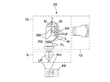
- FIG. 2 is a schematic diagram illustrating a configuration example of a projection-type image display device.
- the image display device 20 includes a light source 5, an illumination optical system 10, and a projection optical system 15.
- the light source 5 is disposed so as to emit a light beam to the illumination optical system 10.
- a high pressure mercury lamp or the like is used as the light source 5.
- a solid light source such as an LED (Light Emitting Diode) or an LD (Laser Diode) may be used.
- the illumination optical system 10 uniformly irradiates the light beam emitted from the light source 5 onto the surface of the image modulation element (liquid crystal panel P) serving as the primary image surface.
- the light beam from the light source 5 passes through the two fly-eye lenses FL, the polarization conversion element PS, and the condenser lens L in order, and is converted into a uniform light beam with uniform polarization.
- the light flux that has passed through the condenser lens L is separated into RGB color component lights by a dichroic mirror DM that reflects only light in a specific wavelength band.
- a dichroic mirror DM that reflects only light in a specific wavelength band.
- Each color component light of RGB is incident on a liquid crystal panel P (image modulation element) provided corresponding to each color of RGB via a total reflection mirror M, a lens L, and the like. Then, each liquid crystal panel P performs light modulation according to the video signal.
- the light-modulated color component lights are combined by the dichroic prism PP to generate image light.
- the generated image light is emitted toward the projection optical system 15.
- the optical components constituting the illumination optical system 10 are not limited, and optical components different from the optical components described above may be used.
- a transmissive liquid crystal panel P a reflective liquid crystal panel, a digital micromirror device (DMD), or the like may be used as the image modulation element.
- a dichroic prism PP instead of the dichroic prism PP, a polarization beam splitter (PBS), a color synthesis prism that synthesizes RGB video signals, a TIR (Total Internal Reflection) prism, or the like may be used.
- the illumination optical system 10 corresponds to an image generation unit.
- the projection optical system 15 adjusts the image light emitted from the illumination optical system 10 and performs an enlarged projection on a screen serving as a secondary image plane. That is, the projection optical system 15 adjusts the image information of the primary image plane (liquid crystal panel P) and enlarges and projects it on the secondary image plane (screen).
- FIG. 3 and 4 are schematic diagrams illustrating a configuration example of the image display system according to the first embodiment of the present technology.
- FIG. 3 is a view of the image display system 100 as viewed from above.
- FIG. 4 is a diagram of the image display system 100 as viewed obliquely from above the right front side.
- the image display system 100 includes a curved screen 30 and two image display devices 20.
- the curved screen 30 includes both a screen whose overall shape is a curved surface and a screen whose at least a part is a curved shape.
- a curved screen 30 having a substantially arc shape when used from above is used.
- the curved screen 30 is erected along the vertical direction and installed so as to extend in the horizontal direction.
- the left and right end portions 31a and 31b of the curved screen 30 are bent forward and disposed at substantially equal positions in the front-rear direction.
- a substantially central portion in the left-right direction of the curved screen 30 is located on the most rear side and corresponds to a vertex of a substantially arc shape as viewed from above.
- the shape of the curved screen 30 may be expressed as a shape that is substantially equal to a part of the inner surface of the column that is erected along the vertical direction. Further, the curved screen 30 may be configured by connecting minute planar regions while changing the angle thereof.
- the specific configuration such as the material, size, and radius of curvature of the curved screen 30 is not limited and may be arbitrarily designed. Further, the curved screen 30 may be realized by adhering a flexible screen member to the inner surface of the base portion having an arc shape when viewed from above. In the present embodiment, the curved screen 30 corresponds to a projection object.
- the two image display devices 20 include a first image display device 20a and a second image display device 20b.
- the first image display device 20a is installed at a substantially central portion in the vertical direction of the left end portion 31a of the curved screen 30 so that an image can be projected rearward.
- the first image display device 20a projects an image 21a (hereinafter referred to as a first image) 21a onto the left region of the curved screen 30 bent in a substantially arc shape.
- the second image display device 20b is installed at a substantially central portion of the right end portion 31b of the curved screen 30 in the vertical direction so that an image can be projected rearward.
- the second image display device 20b projects an image (hereinafter, referred to as a second image) 21b onto a region on the right side of the curved screen 30 bent in a substantially arc shape.
- the holding mechanism (not shown) that holds the first and second image display devices 20a and 20b may be arbitrarily designed.
- the first and second image display devices 20a and 20b are arranged so that the first and second images 21a and 21b are overlapped so that the first and second images 21a and 21b overlap each other. 21b is projected.
- the image modulation elements (liquid crystal panel P) provided in the first and second image display devices 20a and 20b have a rectangular shape having a long side direction and a short side direction.
- the liquid crystal panel P generates image light that forms a rectangular image.
- the first and second images 21a and 21b are respectively projected as equal rectangular images. Then, the first and second images 21a and 21b are respectively projected along the long side direction (left and right direction) of the first and second images 21a and 21b so as to overlap each other. Accordingly, an overlapping region 22 in which the first and second images 21 a and 21 b overlap each other is generated at a substantially central portion of the curved screen 30.
- the stitching process is executed in the overlapping region 22 where the first and second images 21a and 21b overlap.
- the first and second images 21a and 21b are connected and synthesized as one image.
- one large image is displayed in a substantially entire area along the left-right direction of the curved screen 30.
- a specific algorithm or the like of the stitching process is not limited, and any stitching technique may be used.
- FIG. 3 the first image light 23a constituting the first image 21a projected from the first image display device 20a and the pixel lights Ca1, Ca2, and Ca3 included in the first image light 23a are schematically illustrated. Is shown in FIG.
- the first image light 23b constituting the second image 21b projected from the second image display device 20b and the pixel lights Cb1, Cb2, and Cb3 included in the second image light 23b are schematically shown. It is shown schematically.
- the pixel light is light for constituting each of a plurality of pixels included in the projected image.
- light emitted from each of a plurality of pixels included in an image modulation element (liquid crystal panel P) that generates and emits image light is pixel light. Therefore, the image light includes a plurality of pixel lights.
- the pixel light Ca1 shown in FIG. 3 is pixel light for constituting the left end pixel of the first image 21a. Accordingly, the pixel light Ca1 corresponds to a light beam at the left end of the first image light 23a.
- the pixel light Ca2 is pixel light for constituting the pixel at the right end of the first image 21a. Accordingly, the pixel light Ca2 corresponds to the light beam at the right end of the first image light 23a.
- the pixel light Ca3 is pixel light for constituting the pixel at the left end of the overlapping region 22 where the first and second images 21a and 21b overlap. Accordingly, among the light rays included in the first image light 23 a, the light rays from the pixel lights Ca ⁇ b> 3 to Ca ⁇ b> 2 become image light constituting the overlapping region 22. On the other hand, among the light rays included in the first image light 23 a, the light rays from the pixel lights Ca ⁇ b> 1 to Ca ⁇ b> 3 become image light constituting an area other than the overlapping area 22.
- the pixel light Cb1 shown in FIG. 3 is pixel light for constituting the pixel at the right end of the second image 21b. Accordingly, the pixel light Cb1 corresponds to a light beam at the right end of the second image light 23b.
- the pixel light Cb2 is pixel light for constituting the pixel at the left end of the second image 21b. Accordingly, the pixel light Cb2 corresponds to the light beam at the left end of the first image light 23a.
- the pixel light Ca3 is pixel light for constituting the pixel at the right end of the overlapping region 22. Accordingly, among the light rays included in the second image light 23b, the light rays from the pixel lights Cb3 to Cb2 become image light constituting the overlapping region 22. On the other hand, among the light rays included in the second image light 23b, the light rays from the pixel lights Cb1 to Cb3 become image light constituting an area other than the overlapping area 22.
- the first and second image display devices 20a and 20b are images that constitute an area other than the overlapping area 22 where the first and second images 21a and 21b overlap each other.
- the first and second images 21a and 21b are projected so that the light does not cross each other.
- the user 3 views the first and second images 21a and 21b synthesized into one sheet from the inner area (for example, a position close to the overlapping area 22) of the curved screen 30 bent into an arc shape. It becomes possible. As a result, it is possible to realize a sense of immersion in very high content, and to provide the user 3 with an excellent visual effect.
- the direction in which the first and second images 21a and 21b overlap is not limited.
- the first and second images 21a and 21b may be projected so as to overlap each other along the short side direction of the first and second images 21a and 21b.
- the first and second images 21a and 21b may be projected so as to overlap each other along the short side direction of the first and second images 21a and 21b.
- rectangular first and second images 21a and 21b having a short side direction in the left-right direction are projected.
- the 1st and 2nd images 21a and 21b are projected so that the 1st and 2nd images 21a and 21b may overlap along the short side direction of the 1st and 2nd images 21a and 21b. Good.
- the image when image light constituting a rectangular image is projected, the image may be displayed in a shape different from the rectangular shape.
- directions corresponding to the long side direction and the short side direction of the liquid crystal panel P can be defined as the long side direction and the short side direction of the image.
- a plurality of images can be overlapped along the long side direction or the short side direction.
- the long side direction and the short side direction of the liquid crystal panel P may be expressed as the long side direction and the short side direction of the image light.
- first and second image display devices 20a and 20b and the curved screen 30 Detailed configuration examples of the first and second image display devices 20a and 20b and the curved screen 30 will be described.
- image display devices having substantially the same configuration are used as the first and second image display devices 20a and 20b.
- the projection optical system 15 and the curved screen 30 of the first and second image display devices 20a and 20b will be described.
- FIG. 5 and 6 are optical path diagrams showing a schematic configuration example of the projection optical system 15 according to the present embodiment.
- FIG. 6 one projection optical system 15 and a portion on which the image of the curved screen S is projected are shown.
- the image display system 100 having the curved screen 30 and the first and second image display devices 20a and 20b shown in FIG. 3 and FIG. It is possible to realize.
- the liquid crystal panel P and the dichroic prism PP of the illumination optical system 10 are schematically shown.
- the emission direction of the image light emitted from the dichroic prism PP to the projection optical system 15 is defined as the Z direction.
- the horizontal direction of the primary image plane (liquid crystal panel P) is the X direction
- the vertical direction is the Y direction.
- the X and Y directions are directions corresponding to the horizontal direction and the vertical direction of an image constituted by image light.
- the projection optical system 15 includes a first optical system L1 and a second optical system L2.
- the first optical system L1 is configured at a position where the image light generated by the illumination optical system 10 is incident, and has a positive refractive power as a whole.
- the first optical system L1 is configured with a reference axis extending in the Z direction (hereinafter, this reference axis is referred to as an optical axis O) as a reference.
- the first optical system L1 is substantially the same as the optical axis O in which the optical axes of one or more optical components included in the first optical system L1 are reference axes. Configured to match.
- the optical axis of the optical component is typically an axis passing through the center of the optical surface such as a lens surface or a reflecting surface of the optical component.
- the rotationally symmetric axis corresponds to the optical axis.
- the optical axis O is an axis obtained by extending the optical axis (rotational symmetry axis) of the lens L11 closest to the illumination optical system 10 included in the first optical system L1. That is, another optical component is disposed on an axis obtained by extending the optical axis of the lens L11.
- the image light is emitted along the optical axis O from a position offset from the optical axis O in the vertical direction (Y direction).
- the first optical system L1 corresponds to a lens system.
- the direction along the optical axis O can also be referred to as the optical path traveling direction of the first optical system L1.
- the first optical system L1 has a first reflecting surface Mr1 and a second reflecting surface Mr2.
- the first and second reflecting surfaces Mr1 and Mr2 are concave reflecting surfaces.
- the first reflecting surface Mr1 is a rotationally symmetric spherical surface configured so that the rotationally symmetric axis coincides with the optical axis O.
- the second reflecting surface Mr2 is a rotationally symmetric aspherical surface configured such that the rotationally symmetric axis coincides with the optical axis O, and is configured by only a portion that can reflect an effective region that is an area on which image light is incident. Yes. That is, the entire rotationally symmetric aspherical surface is not disposed, but only the necessary portions of the rotationally symmetric aspherical surface are disposed. This makes it possible to reduce the size of the apparatus.
- the second optical system L2 includes a concave reflecting surface Mr3.
- the concave reflecting surface Mr3 is configured with the optical axis O as a reference axis as a reference, and reflects the image light emitted from the first optical system L1 toward the curved screen S (curved screen 30).
- the concave reflecting surface Mr3 is a rotationally symmetric aspherical surface configured such that the rotationally symmetric axis (optical axis) coincides with the optical axis O, and is configured only by a portion that can reflect an effective region that is an area on which image light is incident.
- the entire rotationally symmetric aspherical surface is not disposed, but only the necessary portions of the rotationally symmetric aspherical surface are disposed. This makes it possible to reduce the size of the apparatus.
- the first optical system L1 and the second optical system L2 are configured on a common optical axis O. That is, the first and second optical systems L1 and L1 are arranged such that the axes obtained by extending the optical axis (rotation symmetry axis) of the lens L11 closest to the illumination optical system 10 substantially coincide with the respective optical axes (rotation symmetry axis). L2 is configured. As a result, the size in the Y direction can be reduced, and the apparatus can be miniaturized.
- FIG. 5 the optical paths of four pixel lights C1, C2, C3, and C4 of the image light emitted from the dichroic prism PP to the projection optical system 15 are illustrated.
- FIG. 6 the optical paths of the three pixel lights C1, C2, and C3 are shown.
- the pixel light C1 corresponds to pixel light emitted from the central pixel of the liquid crystal panel P.
- the pixel light C2 corresponds to pixel light emitted from the pixel closest to the optical axis O at the center of the liquid crystal panel P. This corresponds to pixel light emitted from a pixel farthest from the optical axis O at the center of the liquid crystal panel P.
- the pixel light C4 corresponds to pixel light emitted from the upper rightmost pixel of the liquid crystal panel P.
- the pixel light C2 corresponds to pixel light emitted from the pixel closest to the optical axis O of the liquid crystal panel P.
- the pixel light C3 corresponds to pixel light that is located on a straight line connecting a pixel closest to the optical axis O and a central pixel of the liquid crystal panel P and emitted from a pixel farthest from the optical axis O.
- Image light emitted to the projection optical system 15 along the optical axis O from a position offset in the vertical direction from the optical axis O travels across the optical axis O and enters the first reflecting surface Mr1.
- the image light incident on the first reflecting surface Mr1 is turned back by the first reflecting surface Mr1, travels again across the optical axis O, and enters the second reflecting surface Mr2.
- the image light incident on the second reflecting surface Mr2 is folded by the second reflecting surface Mr2 and emitted from the first optical system L1.
- the image light is emitted toward the concave reflecting surface Mr3 so as to intersect the optical axis O again.
- the image light emitted from the first optical system L1 is reflected by the concave reflecting surface Mr3, which is the second optical system L2, crosses the optical axis O again, and is projected toward the curved screen S.
- the optical path of the image light is configured to intersect the optical axis O.
- the optical path of the image light to the concave reflecting surface Mr3 can be configured in the vicinity of the optical axis O.
- the size of the device in the Y direction can be reduced, and the size of the device can be reduced.
- the image light is folded back and reflected by each of the first and second reflecting surfaces Mr1 and Mr2. This makes it possible to ensure a sufficient optical path length for image light. As a result, the size of the device in the X direction can be reduced, and the size of the device can be reduced.
- At least a part of the light rays included in the image light incident on the concave reflecting surface Mr ⁇ b> 3 is along the optical axis O that is the reference axis by the concave reflecting surface Mr ⁇ b> 3. Reflected in a direction that intersects the direction at an angle of 80 degrees or more.
- the intersecting angle between the traveling direction of the light beam included in the image light reflected by the concave reflecting surface Mr3 and the direction along the optical axis O is defined as follows. First, an intersection between a straight line extending along the optical axis O and a straight line extending along the traveling direction of the light beam reflected by the concave reflecting surface Mr3 is calculated. A straight line extending from the intersection toward the liquid crystal panel P is rotated to the light traveling direction side with respect to the intersection. At that time, the light beam included in the image light reflected by the concave reflecting surface Mr3 has a rotation angle until the straight line extending from the intersection toward the liquid crystal panel P coincides with the straight line extending in the traveling direction of the light beam. Is defined as the angle of intersection between the traveling direction of the lens and the direction along the optical axis O.
- the concave reflecting surface Mr3 is designed so that the intersection angle defined above of at least some of the light rays included in the image light reflected by the concave reflecting surface Mr3 is 80 degrees or more.
- the pixel light C4 included in the image light is reflected in a direction that intersects the direction along the optical axis O at an angle of 80 degrees or more.
- the intersection angle between the traveling direction of the pixel light C4 reflected by the concave reflecting surface Mr3 and the direction along the optical axis O is an angle R1. This angle R1 is 87.4 degrees.
- this angle R1 is the maximum crossing angle. That is, the pixel light C4 is a light beam having the largest intersection angle. Other light rays are reflected in a direction intersecting the direction along the optical axis O at an angle smaller than the angle R1 (87.4 degrees).
- pixel light is taken as an example of light rays included in image light.
- the present invention is not limited to this, and it is only necessary that at least a part of light rays such as a part of light rays included in the pixel light is reflected in a direction intersecting with the direction along the optical axis O at an angle of 80 degrees or more.
- the image display device 20 including the projection optical system 15 illustrated in FIGS. 5 and 6 is installed so that the concave reflection surface Mr3 is disposed at a position corresponding to the shape of the curved screen S.
- the concave reflecting surface Mr3 By designing the concave reflecting surface Mr3 so that the crossing angle becomes large, it is possible to realize high-quality image display corresponding to the curved screen S. This point will be described in detail later.
- the present inventor found four conditions (1) to (4) related to image display corresponding to a curved screen. These conditions will be described with reference to FIGS.
- An angle at which the traveling direction of each light beam included in the image light reflected by the concave reflecting surface Mr3 intersects with the direction along the optical axis O which is the reference axis is defined as ⁇ 1.
- the angle ⁇ 1 corresponds to the intersection angle defined above.
- the angle ⁇ 1 of the light beam with the largest angle ⁇ 1 is defined as ⁇ 1max.
- the crossing angle of the pixel light C4 is ⁇ 1max.
- the projection optical system 15 is configured to satisfy the following relationship. (1) 80 degrees ⁇ ⁇ 1max ⁇ 160 degrees
- This conditional expression (1) regulates an appropriate reflection angle of the light beam included in the image light.
- ⁇ 1max is less than the lower limit specified in the conditional expression (1), the light beam is not reflected at a large angle, and it becomes difficult to correspond to the curved screen S.
- ⁇ 1max exceeds the upper limit defined in the conditional expression (1), there is a high possibility that the light beam interferes with the concave reflecting surface Mr3 itself. That is, after being reflected by the concave reflecting surface Mr3, there is a high possibility that the light will enter the other portion of the concave reflecting surface Mr3 again.
- intersection angle of the pixel light C4 is 87.4 degrees, which satisfies the condition 1.
- the concave reflecting surface Mr3 is configured such that the rotational symmetry axis coincides with the optical axis O that is the reference axis.
- h be the height of light from the optical axis O of the light incident on the concave reflecting surface Mr3.
- hmax be the ray height corresponding to the reflection point farthest from the optical axis O that reflects the image light.
- the average value of Z ′ (h) from the optical axis O to the beam height hmax is calculated as Z′ave.
- the projection optical system 15 is configured to satisfy the following relationship: (2) 1 ⁇
- This conditional expression (2) regulates an appropriate reflection angle of the light beam included in the image light.
- the optical path length of the pixel light emitted from the pixel closest to the optical axis O of the liquid crystal panel P to the curved screen S is Lp1, and is located on a straight line connecting the pixel closest to the optical axis O and the central pixel of the liquid crystal panel P.
- the optical path length of the pixel light emitted from the pixel farthest from the optical axis O to the curved screen S is Lp2.
- the optical path length of the pixel light C2 is Lp1
- the optical path length of the pixel light C3 is Lp2.
- the projection optical system 15 and the curved screen S are configured so as to satisfy the following relationship. (3) 0.005 ⁇ Lp1 / Lp2 ⁇ 0.5
- This conditional expression (3) corresponds to the conditional expression for defining the movable area of the user 3 illustrated in FIG.
- Lp1 / Lp2 is less than the lower limit prescribed in the conditional expression (3), even when the user 3 stands near the screen S, generation of shadows can be suppressed, and the movable area of the user 3 can be increased. Can take. On the other hand, there is a high possibility that the optical performance will be reduced because the optical path length difference becomes too large.
- Lp1 / Lp2 exceeds the upper limit defined in the conditional expression (3), if the user 3 does not move away from the screen S, the light beam interferes with the user 3 and a shadow of the user 3 is generated. Further, it is necessary to move the projection optical system 15 away from the curved screen S, and the entire apparatus becomes large.
- the light path length of the light beam having the shortest light path length to the curved screen S is Ln
- the light path length of the light beam having the longest light path length is Lf
- the optical path length of the pixel light C2 is Ln
- the optical path length of the pixel light C3 is Lf.
- the projection optical system 15 and the curved screen S are configured so as to satisfy the following relationship. (4) 0.005 ⁇ Ln / Lf ⁇ 0.5
- This conditional expression (4) corresponds to the conditional expression for defining the movable area of the user 3 illustrated in FIG. 3 as in the case of the conditional expression (3). That is, when Ln / Lf is less than the lower limit specified in the conditional expression (4), the shadow can be prevented from being generated even when the user 3 stands near the screen S. It can be taken big. On the other hand, there is a high possibility that the optical performance will be reduced because the optical path length difference becomes too large. When Ln / Lf exceeds the upper limit defined in the conditional expression (4), if the user 3 does not move away from the screen S, the light beam interferes with the user 3 and a shadow of the user 3 is generated. Further, it is necessary to move the projection optical system 15 away from the curved screen S, and the entire apparatus becomes large.
- each of the conditional expressions (1) to (4) are not limited to the above values.
- each value can be appropriately changed according to the configuration of the illumination optical system 10, the projection optical system 15, the curved screen S, and the like.
- arbitrary values included in the above-described range may be selected as the lower limit value and the upper limit value and set as the optimum range again.
- conditional expression (1) can be set in the following range. 85 degrees ⁇ ⁇ 1max ⁇ 160 degrees 80 degrees ⁇ ⁇ 1max ⁇ 140 degrees 85 degrees ⁇ ⁇ 1max ⁇ 140 degrees
- conditional expression (2) can be set within the following range. 1 ⁇
- the projection optical system 15 configured as described above will be briefly described with specific numerical examples.
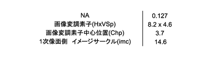
- FIG. 7 is a table showing an example of parameters relating to image projection.
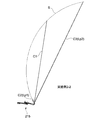
- FIG. 8 is a schematic diagram for explaining the parameters shown in FIG.
- the numerical aperture NA on the primary image plane side of the projection optical system 15 is 0.127.
- the horizontal and vertical lengths (H ⁇ VSp) of the image modulation element (liquid crystal panel P) are 8.2 mm and 4.6 mm.
- the center position (Chp) of the image modulation element is a position 3.7 mm above the optical axis O.
- the image circle (imc) on the primary image plane side is ⁇ 14.6 mm.
- the light emitted from the central pixel of the liquid crystal panel P shown in FIG. 8 corresponds to the pixel light C1 shown in FIG.
- the light emitted from the pixel closest to the optical axis O at the center of the liquid crystal panel P corresponds to the pixel light C2 (the same reference numeral is given).
- the light emitted from the pixel farthest from the optical axis O at the center of the liquid crystal panel P corresponds to the pixel light C3 (the same reference numeral is given).
- the light emitted from the pixel at the upper right end of the liquid crystal panel P corresponds to the pixel light C4 shown in FIG.
- the pixel light C4 emitted from this pixel is reflected by the concave reflecting surface Mr3 in a direction intersecting with the direction along the optical axis O at an angle of 80 degrees or more.
- FIG. 9 shows lens data of the image display device and curved screen data.
- FIG. 9 shows data on 1 to 24 optical components (lens surfaces) arranged from the primary image plane (P) side to the secondary image plane (S) side and the curved screen S. Yes.
- the radius of curvature (mm) As data of each optical component (lens surface), the radius of curvature (mm), the core thickness d (mm), the refractive index nd at the d line (587.56 nm), and the Abbe number ⁇ d at the d line are described.
- the radius of curvature (mm) is described.
- optical component having an aspherical surface complies with the following formula.
- FIG. 10 is a table showing an example of an aspherical coefficient of an optical component included in the projection optical system.
- FIG. 10 shows aspheric coefficients for the aspherical optical components 12, 13, 15, and 24 to which an asterisk (*) is added in FIG. 9.
- the aspheric coefficient in the example corresponds to the above equation (Equation 1).
- the expression (Equation 1) corresponds to a function Z (h) representing the shape of the concave reflecting surface Mr3 according to the light beam height.
- the sag amount Z when the light beam height h shown in FIG. 5 is input to the equation (Equation 1) is used as a parameter representing the shape of the concave reflecting surface Mr3 corresponding to the light beam height.
- the “sag amount” is the distance in the optical axis direction between the plane and a point on the lens surface when a plane that passes through the surface vertex and is perpendicular to the optical axis is set up.
- FIG. 10 shows the eccentric component of the curved screen S in the XYZ directions and the rotational components around the XYZ axes.
- XDE, YDE, and ZDE illustrated in FIG. 10 indicate an X direction component (unit: mm), a Y direction component (unit: mm), and a Z direction component (unit: mm) of surface eccentricity.
- ADE, BDE, and CDE are the ⁇ x direction component (rotation component around the X axis; unit: degree), ⁇ y direction component (rotation component around the Y axis; unit: degree), and ⁇ z direction component (Z) of the surface rotation. Rotational component around the axis; unit: degree).
- FIG. 11 is a table showing Z (h) and Z ′ (h) at the light beam height h.
- the sag amount that is Z (h) is described as “shape” (unit: mm).
- the slope of the tangent line that is Z ′ (h) is described as “thita”.
- the displacement amount of the tangential slope according to the displacement of the light beam height h is described as “ ⁇ ”. The calculation is performed after normalizing the light beam height h, assuming that the light beam height of the optical axis O is 0 and the light beam height hmax is 1.
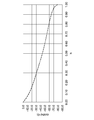
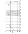
- FIG. 12 is a graph showing the relationship between the light beam height h and “thita”.
- FIG. 13 is a graph showing the relationship between the ray height h and “ ⁇ ”. It can be seen that the slope of the tangent line changes greatly from 0.9 to 1.00 at the height of the ray far from the optical axis O. This means that the curvature increases from the light beam height of 0.9 to 1.00. As a result, the crossing angle ⁇ 1 can be increased.
- FIG. 14 is a table showing numerical values of parameters used in the conditional expressions (2) to (4) described above in the present embodiment.
- the concave reflection surface Mr3 allows at least a part of the light rays of the image light to be in the direction along the optical axis O which is a reference in configuring the projection optical system 15 and 80. Reflected in a direction intersecting at an angle of more than degrees. Thereby, for example, it is possible to cope with projection of an image onto the curved screen S or the like, and it is possible to realize high-quality image display.
- FIG. 15 is a schematic diagram for explaining the projection of an image onto a curved screen by an image display device given as a comparative example.
- the image display device 90 is an ultra-wide-angle projector, and the configuration of the concave reflection surface that reflects image light to the curved screen is different from that of the image display device 20 according to the present embodiment.
- the concave reflecting surface reflects all the light rays included in the image light in a direction intersecting with the optical axis serving as a reference in constituting the projection optical system at an angle of less than 80 degrees.
- the image 91 displayed on the flat screen S ′ and the image 92 displayed on the curved screen S have different shapes.
- the image 92 displayed on the curved screen S is a very distorted image.
- the image display device 90 in order to display the image 92 over a wide range of the curved screen S, the image display device 90 must be installed at a position away from the curved screen S. As a result, the presence of the image display device 90 becomes conspicuous for the user who views the image 92, and the feeling of immersion in the content is impaired. In addition, since the area where the shadow of the user appears is large, the area where the user can move is small. As a result, it becomes difficult to provide an excellent viewing environment.
- the range that can be reflected by the concave reflecting surface Mr3 is widely designed to be 80 degrees or more with respect to the reference optical axis O. As a result, it is possible to suppress distortion of the image optically displayed on the surface screen S. As a result, the electrical correction amount for the image signal can be sufficiently suppressed. As a result, it is possible to display an image with high image quality.
- the image display device according to the present technology is obtained. It can also be easily realized.
- 16 to 18 are optical path diagrams showing a schematic configuration example of the projection optical system 215 according to the present embodiment. 17 and 18, the configuration of the curved screen S is different from each other.
- the configuration example illustrated in FIG. 17 may be referred to as Example 2-1
- the configuration example illustrated in FIG. 18 may be referred to as Example 2-2.
- the concave reflecting surface Mr3 causes at least a part of the light rays included in the image light incident on the concave reflecting surface Mr3 to be 80 degrees or more in the direction along the optical axis O that is the reference axis. Reflected in the direction of crossing at an angle of.
- the pixel light C4 included in the image light is reflected in a direction intersecting with the direction along the optical axis O at an angle of 80 degrees or more.
- the crossing angle R1 between the traveling direction of the pixel light C4 reflected by the concave reflecting surface Mr3 and the direction along the optical axis O is 128.2 degrees. It can also be seen that this angle R1 is the maximum crossing angle and satisfies the conditional expression (1).
- the pixel light C3 is also reflected in a direction that intersects the direction along the optical axis O at an angle of 80 degrees or more.
- the intersection angle of the pixel light C3 is 122.5 degrees.
- FIG. 19 is a table showing an example of parameters relating to image projection.
- FIG. 20 shows lens data of the image display device and curved screen data.
- FIG. 21 is a table showing an example of an aspheric coefficient of an optical component included in the projection optical system.
- FIG. 21 shows the eccentric components in the XYZ directions and the rotational components around the XYZ axes of the curved screen of Example 2-1 and the curved screen of Example 2-2.
- FIG. 22 is a table showing Z (h) and Z ′ (h) at the light beam height h.
- FIG. 23 is a graph showing the relationship between the ray height h and “thita”.
- FIG. 24 is a graph showing the relationship between the ray height h and “ ⁇ ”.
- FIG. 25 is a table showing numerical values of parameters used in the above conditional expressions (2) to (4) in the present embodiment.
- the concave reflection surface Mr3 according to the first and second embodiments has a larger curvature from the light ray height of 0.9 to 1.00. Focusing on this, one feature of the concave reflecting surface Mr3 according to the present technology can be defined by the following conditional expression.
- the projection optical system is configured so as to satisfy the following relationship: 1 ⁇
- These expressions are conditional expressions derived based on the feature that the shape change due to the light beam height of 0.9 to 1.00 is larger than the range of other light beam heights.
- the projection optical system according to the present technology may be configured using these conditional expressions.
- FIG. 26 is an optical path diagram showing a schematic configuration example of a projection optical system according to another embodiment.
- the planar reflection surface Mr4 is disposed between the first optical system L1 and the concave reflection surface Mr3 which is the second optical system L2.
- the optical path traveling direction of the first optical system L1 is bent by the plane reflecting surface Mr4.
- Such a configuration may be adopted.
- the concave reflecting surface Mr3 may be appropriately configured with the bent optical axis O ′ as the reference axis. That is, the concave surface is such that at least a part of the light rays included in the image light incident on the concave reflecting surface Mr3 is reflected in a direction intersecting with the direction along the optical axis O ′ that is the reference axis at an angle of 80 degrees or more.
- a reflecting surface Mr3 is formed.
- the concave reflecting surface Mr3 is configured so that there is a light beam having an intersection angle ⁇ 1 shown in FIG. In FIG. 26, the intersection angle ⁇ 1 of the pixel light C4 (not shown) is configured to be 80 degrees or more.
- FIG. 27 and FIG. 28 are schematic views showing a configuration example of an image display system according to another embodiment.
- a curved screen S having a dome shape is used.
- the dome shape is not limited to the hemispherical shape, and includes an arbitrary shape that can cover the upper part over 360 degrees.
- first and second image display devices 420a and 420 are installed below the dome-shaped curved screen S so as to face each other in the left-right direction.
- the first and second image display devices 420a and 420b are installed so as to project the first and second images 421a and 421b upward, respectively.
- 1st and 2nd image 421a and 421b are projected so that it may mutually overlap along a long side direction (left-right direction). Accordingly, an overlapping area 422 where the first and second images 421a and 421b overlap each other is generated at the apex portion of the curved screen S. Stitching processing is executed using the overlapping area 422 as a reference, and one large image is displayed.
- the image display device according to the present technology described above As the first and second image display devices 420a and 420b, high-quality image display corresponding to the dome shape can be realized, and an excellent viewing environment can be realized. It becomes possible to provide.
- first to third image display devices 520a to 520b are arranged below the dome-shaped curved screen S at equal intervals along the circumference.
- the first to third image display devices 520a to 520c are installed so as to project the first to third images 521a to 521c upward.
- image light for forming a rectangular image is projected as the first to third images 521a to 521c.
- each of the first to third images 521a to 521c is schematically illustrated in a rectangular shape, but the shape displayed on the curved screen S is different from the rectangular shape.
- the first to third images 521a and 521b are projected at positions symmetrical to each other with respect to the vertex of the curved screen S so as to overlap each other. Then, the stitching process is performed in the overlapping areas 522a to 522c, and one large image is displayed.
- the image display device according to the present technology described above As the first to third image display devices 520a to 520c, high-quality image display corresponding to the dome shape can be realized, and an excellent viewing environment can be achieved. It becomes possible to provide. Thus, the present technology is applicable even when three or more image display devices are used.
- a free curved surface having no rotational symmetry axis may be used as the concave reflecting surface that reflects the image light on the screen.
- the optical axis of the concave reflecting surface (for example, an axis passing through the center of the optical surface) is aligned with a reference axis that is a reference in configuring the lens system.
- the concave reflecting surface is appropriately designed so that at least a part of the light rays included in the image light is reflected in a direction intersecting with the direction along the reference axis at an angle of 80 degrees or more. As a result, the same effects as described above can be exhibited.
- the projection object is not limited to a curved screen.
- the present technology can be applied to display an image on an arbitrary projection object such as a wall of a table or a building.
- high-quality image display corresponding to a projection object having a curved surface shape can be realized.
- “match”, “equal”, “vertical”, “rectangular”, “dome shape”, “symmetric”, and the like are “substantially coincide”, “substantially equal”, “substantially vertical”, “substantially rectangular”.
- the concept includes “shape”, “substantially dome shape”, and “substantially symmetrical”. For example, within a predetermined range (for example, a range of ⁇ 10%) based on “perfectly matched”, “perfectly equal”, “fully vertical”, “fully rectangular”, “fully dome-shaped”, “fully symmetric”, etc.
- the included states are also included.
- this technique can also take the following structures.
- a light source An image generation unit that generates image light by modulating light emitted from the light source;
- a lens system configured with a reference axis as a reference at a position where the generated image light is incident, and having a positive refractive power as a whole;
- a projection optical system configured with the reference axis as a reference, and having a concave reflection surface that reflects the image light emitted from the lens system toward a projection object, and The concave reflecting surface reflects at least a part of light rays included in the image light incident on the concave reflecting surface in a direction intersecting with the direction along the reference axis at an angle of 80 degrees or more.
- the image display device includes a plurality of pixel lights, The concave reflecting surface reflects at least one pixel light of the plurality of pixel lights in a direction intersecting with a direction along the reference axis at an angle of 80 degrees or more.
- the image display device according to (1) or (2), The angle at which the traveling direction of each light ray included in the image light reflected by the concave reflecting surface intersects the direction along the reference axis is ⁇ 1, and the angle ⁇ 1 of the light ray with the largest angle ⁇ 1 is ⁇ 1max. Then An image display device configured to satisfy a relationship of 80 degrees ⁇ ⁇ 1max ⁇ 160 degrees.
- the concave reflecting surface is configured such that a rotational symmetry axis coincides with the reference axis;
- the ray height from the reference axis is h
- the derivative of the function Z (h) representing the shape of the concave reflecting surface according to the ray height is differentiated by the ray height, Z ′ (h)
- the image light Hmax is a light ray height corresponding to a reflection point farthest from the reference axis
- an average value of Z ′ (h) from the reference axis to the light ray height hmax is Z′ave.
- the reference axis is an axis obtained by extending an optical axis of a lens closest to the image generation unit included in the lens system.
- a projection optical system that projects image light generated by modulating light emitted from a light source, A lens system configured with a reference axis as a reference at a position where the generated image light is incident, and having a positive refractive power as a whole; A concave reflecting surface configured with the reference axis as a reference and reflecting the image light emitted from the lens system toward a projection object, The concave reflecting surface reflects at least a part of light rays included in the image light incident on the concave reflecting surface in a direction intersecting with the direction along the reference axis at an angle of 80 degrees or more.
- An image display system comprising: a display device.
- the image generation unit includes an image modulation element that emits the image light
- the image modulation element has a plurality of pixels each emitting pixel light, emits the image light including a plurality of pixel lights emitted from the plurality of pixels
- the optical path length of the pixel light emitted from the pixel closest to the reference axis of the image modulation element to the projection object is Lp1
- the straight line connecting the pixel closest to the reference axis to the center pixel of the image modulation element When the optical path length of the pixel light emitted from the pixel farthest from the reference axis to the projection object is Lp2, 0.005 ⁇ Lp1 / Lp2 ⁇ 0.5
- An image display system configured to satisfy the relationship.
- the image display system according to any one of (10) to (13),
- the one or more image display devices include a first image display device that projects a first image onto the curved screen, and a second image display device that projects a second image onto the curved screen,
- the first image display device and the second image display device respectively project the first image and the second image so that the first image and the second image overlap each other.
- Display system (15)
- An image display system that projects one image and the second image, respectively.
- the image display system according to (14) or (15), The image generation unit generates the image light constituting a rectangular image, In the first image display device and the second image display device, the first image and the second image overlap each other along the long side direction of the first image and the second image. As described above, the image display system that projects the first image and the second image, respectively.
- the image display system according to (14) or (15), The image generation unit generates the image light constituting a rectangular image, In the first image display device and the second image display device, the first image and the second image overlap each other along the short side direction of the first image and the second image. As described above, the image display system that projects the first image and the second image, respectively.
- the projection object is a screen having a dome shape.
- the one or more image display devices include an image display system including three or more image display devices.
Landscapes
- Physics & Mathematics (AREA)
- General Physics & Mathematics (AREA)
- Engineering & Computer Science (AREA)
- Multimedia (AREA)
- Signal Processing (AREA)
- Optics & Photonics (AREA)
- Projection Apparatus (AREA)
- Lenses (AREA)
- Transforming Electric Information Into Light Information (AREA)
- Liquid Crystal (AREA)
Abstract
Description
前記画像生成部は、前記光源から出射される光を変調して画像光を生成する。
前記投射光学系は、レンズ系と、凹面反射面とを有する。
前記レンズ系は、前記生成された画像光が入射する位置に基準軸を基準として構成され、全体で正の屈折力を有する。
前記凹面反射面は、前記基準軸を基準として構成され、前記レンズ系から出射された前記画像光を被投射物に向けて反射する。また前記凹面反射面は、前記凹面反射面に入射する前記画像光に含まれる少なくとも一部の光線を、前記基準軸に沿った方向と80度以上の角度で交差する方向へ反射する。
80度≦θ1max≦160度
の関係を満たすように構成されていてもよい。
1<|Z'(1.0・hmax)-Z'(0.9・hmax)|/|Z'ave.|<20
の関係を満たすように構成されていてもよい。
前記1以上の画像表示装置は、各々が、前記光源と、前記画像生成部と、前記投射光学系とを有する。
また画像表示システムは、前記画像変調素子の前記基準軸に最も近い画素から出射される画素光の前記被投射物までの光路長をLp1、前記基準軸に最も近い画素から前記画像変調素子の中央の画素を結ぶ直線上に位置し前記基準軸から最も遠い画素から出射される画素光の前記被投射物までの光路長をLp2とすると、
0.005<Lp1/Lp2<0.5
の関係を満たすように構成されていてもよい。
0.005<Ln/Lf<0.5
の関係を満たすように構成されていてもよい。
投射型の画像表示装置の概要について、液晶プロジェクタを例に挙げて簡単に説明する。液晶プロジェクタは、光源から照射される光を空間的に変調することで、映像信号に応じた光学像(画像光)を形成する。光の変調には、画像変調素子である液晶表示素子等が用いられる。例えばRGBのそれぞれに対応するパネル状の液晶表示素子(液晶パネル)を備えた、三板式の液晶プロジェクタが用いられる。
画面(スクリーン)に人間等の影が映らないため、効率的なプレゼンテーションが可能である。
設置場所の選択の自由度が高く、狭い設置空間や障害物が多い天井等にも、簡単に設置可能である。
壁に設置して使用することで、天井に設置する場合と比べてケーブルの引き回し等のメンテナンスが容易である。
例えば打ち合わせスペース、教室、及び会議室等のセッティングの自由度を増やすことが可能である。
[画像表示システム]
図3及び図4は、本技術の第1の実施形態に係る画像表示システムの構成例を示す模式図である。図3は、画像表示システム100を上方から見た図である。図4は、画像表示システム100を、右前側の上方から斜めに見た図である。
凹面反射面Mr3により反射された画像光に含まれる各光線の進行方向と、基準軸である光軸Oに沿った方向とが交差する角度をθ1とする。角度θ1は、上記で規定した交差角度に相当する。
最も角度θ1が大きくなる光線の角度θ1をθ1maxとする。図5に示す例では、画素光C4の交差角度が、θ1maxとなる。
この場合、以下の関係を満たすように、投射光学系15が構成される
(1) 80度≦θ1max≦160度
凹面反射面Mr3は、回転対称軸が基準軸である光軸Oと一致するように構成される。
凹面反射面Mr3に入射する光の光軸Oからの光線高さをhとする。
光線高さに応じた凹面反射面Mr3の形状を表す関数Z(h)を光線高さで微分した導関数をZ'(h)(=dZ/dh)とする。従って、導関数Z'(h)は、光線高さhにおける凹面反射面Mr3に接する直線の傾きに相当する。
画像光を反射する光軸Oから最も離れた反射点に対応する光線高さをhmaxとする。
光軸Oから光線高さhmaxまでのZ'(h)の平均値をZ'ave.とする。
この場合、以下の関係を満たすように、投射光学系15が構成される
(2) 1<|Z'(1.0・hmax)-Z'(0.9・hmax)|/|Z'ave.|<20
液晶パネルPの光軸Oに最も近い画素から出射される画素光の曲面スクリーンSまでの光路長をLp1、光軸Oに最も近い画素から液晶パネルPの中央の画素を結ぶ直線上に位置し光軸Oから最も遠い画素から出射される画素光の曲面スクリーンSまでの光路長をLp2とする。本実施形態では、画素光C2の光路長がLp1となり、画素光C3の光路長がLp2となる。
この場合、以下の関係を満たすように、投射光学系15、及び曲面スクリーンSが構成される。
(3) 0.005<Lp1/Lp2<0.5
画像光に含まれる光線のうち、曲面スクリーンSまでの光路長が最も短い光線の光路長をLn、最も光路長が長い光線の光路長をLfとする。図6に示す例では、画素光C2の光路長がLnとなり、画素光C3の光路長がLfとなる。
この場合、以下の関係を満たすように、投射光学系15、及び曲面スクリーンSが構成される。
(4) 0.005<Ln/Lf<0.5
85度≦θ1max≦160度
80度≦θ1max≦140度
85度≦θ1max≦140度
1<|Z'(1.0・hmax)-Z'(0.9・hmax)|/|Z'ave.|<10
2<|Z'(1.0・hmax)-Z'(0.9・hmax)|/|Z'ave.|<10


|Z'(1.0・hmax)-Z'(0.9・hmax)| 11.8
|Z'ave.| 5.7
|Z'(1.0・hmax)-Z'(0.9・hmax)|/|Z'ave.| 2.07
C1の光路長 1031.11mm
C2の光路長(=Lp1=Ln) 634.76mm
C3の光路長(=Lp2=Lf) 1311.61mm
C4の光路長 1236.61mm
Lp1/Lp2 0.48
Ln/Lf 0.48
このような結果となり、条件式(2)~(4)を満たしていることが分かる。
本技術に係る第2の実施形態の画像表示システムについて説明する。これ以降の説明では、上記の実施形態で説明した画像表示システム100、及び画像表示装置20における構成及び作用と同様な部分については、その説明を省略又は簡略化する。
図20は、画像表示装置のレンズデータ、及び曲面スクリーンのデータである。
図21は、投射光学系に含まれる光学部品の非球面係数の一例を示す表である。また図21には、実施例2-1の曲面スクリーン及び実施例2-2の曲面スクリーンの、XYZ方向における偏心成分、及びXYZの各軸回りの回転成分が記載されている。
図23は、光線高さhと「thita」との関係を示すグラフである。
図24は、光線高さhと「Δθ」との関係を示すグラフである。
|Z'(1.0・hmax)-Z'(0.9・hmax)| 13.7
|Z'ave.| 7.8
|Z'(1.0・hmax)-Z'(0.9・hmax)|/|Z'ave.| 1.75
(実施例2-1)
C1の光路長 933.01mm
C2の光路長(=Lp1=Ln) 418.12mm
C3の光路長(=Lp2) 1195.5mm
C4の光路長(=Lf) 1277.93mm
Lp1/Lp2 0.35
Ln/Lf 0.33
(実施例2-2)
C1の光路長 1045.3mm
C2の光路長(=Lp1=Ln) 306.5mm
C3の光路長(=Lp2) 1319.84mm
C4の光路長(=Lf) 1329.16mm
Lp1/Lp2 0.23
Ln/Lf 0.23
このような結果となり、条件式(2)~(4)を満たしていることが分かる。なお実施例2-1及び実施例2-2では、画素光C4の光路長がLfとなっている。
本技術は、以上説明した実施形態に限定されず、他の種々の実施形態を実現することができる。
すなわち、以下の関係を満たすように、投射光学系が構成される
1<|Z'(1.0・hmax)-Z'(0.9・hmax)|/|Z'(0.7・hmax)-Z'(0.5・hmax)|<20
1<|Z'(1.0・hmax)-Z'(0.9・hmax)|/|Z'(0.5・hmax)-Z'(0.3・hmax)|<20
(1)光源と、
前記光源から出射される光を変調して画像光を生成する画像生成部と、
前記生成された画像光が入射する位置に基準軸を基準として構成され、全体で正の屈折力を有するレンズ系と、
前記基準軸を基準として構成され、前記レンズ系から出射された前記画像光を被投射物に向けて反射する凹面反射面と
を有する投射光学系と
を具備し、
前記凹面反射面は、前記凹面反射面に入射する前記画像光に含まれる少なくとも一部の光線を、前記基準軸に沿った方向と80度以上の角度で交差する方向へ反射する
画像表示装置。
(2)(1)に記載の画像表示装置であって、
前記画像光は、複数の画素光を含み、
前記凹面反射面は、前記複数の画素光のうち少なくとも1つの画素光を、前記基準軸に沿った方向と80度以上の角度で交差する方向へ反射する
画像表示装置。
(3)(1)又は(2)に記載の画像表示装置であって、
前記凹面反射面により反射された前記画像光に含まれる各光線の進行方向と、前記基準軸に沿った方向とが交差する角度をθ1とし、最も角度θ1が大きくなる光線の角度θ1をθ1maxとすると、
80度≦θ1max≦160度
の関係を満たすように構成されている
画像表示装置。
(4)(1)から(3)のうちいずれか1つに記載の画像表示装置であって、
前記凹面反射面は、回転対称軸が前記基準軸と一致するように構成され、
前記基準軸からの光線高さをh、前記光線高さに応じた前記凹面反射面の形状を表す関数Z(h)を光線高さで微分した導関数をZ'(h)、前記画像光を反射する前記基準軸から最も離れた反射点に対応する光線高さをhmax、前記基準軸から光線高さhmaxまでのZ'(h)の平均値をZ'ave.とすると、
1<|Z'(1.0・hmax)-Z'(0.9・hmax)|/|Z'ave.|<20
の関係を満たすように構成されている
画像表示装置。
(5)(1)から(4)のうちいずれか1つに記載の画像表示装置であって、
前記基準軸は、前記レンズ系に含まれる前記画像生成部に最も近いレンズの光軸を延長した軸である
画像表示装置。
(6)(1)から(5)のうちいずれか1つに記載の画像表示装置であって、
前記レンズ系は、前記レンズ系に含まれる1以上の光学部品の各々の光軸が、前記基準軸に一致するように構成される
画像表示装置。
(7)(1)から(6)のうちいずれか1つに記載の画像表示装置であって、
前記凹面反射面は、前記凹面反射面の光軸が、前記基準軸に一致するように構成される
画像表示装置。
(8)(1)から(3)、及び(5)から(7)のうちいずれか1つに記載の画像表示装置であって、
前記凹面反射面は、回転対称軸を有さない自由曲面である
画像表示装置。
(9) 光源から出射される光を変調して生成された画像光を投射する投射光学系であって、
前記生成された画像光が入射する位置に基準軸を基準として構成され、全体で正の屈折力を有するレンズ系と、
前記基準軸を基準として構成され、前記レンズ系から出射された前記画像光を被投射物に向けて反射する凹面反射面と
を具備し、
前記凹面反射面は、前記凹面反射面に入射する前記画像光に含まれる少なくとも一部の光線を、前記基準軸に沿った方向と80度以上の角度で交差する方向へ反射する
投射光学系。
(10)(A)被投射物と、
(B)各々が、
光源と、
前記光源から出射される光を変調して画像光を生成する画像生成部と、
前記生成された画像光が入射する位置に基準軸を基準として構成され、全体で正の屈折力を有するレンズ系と、
前記基準軸を基準として構成され、前記レンズ系から出射された前記画像光を被投射物に向けて反射する凹面反射面と
を有する投射光学系と
を有し、
前記凹面反射面は、前記凹面反射面に入射する前記画像光に含まれる少なくとも一部の光線を、前記基準軸に沿った方向と80度以上の角度で交差する方向へ反射する
1以上の画像表示装置と
を具備する画像表示システム。
(11)(10)に記載の画像表示システムであって、
前記画像生成部は、前記画像光を出射する画像変調素子を有し、
前記画像変調素子は、各々が画素光を出射する複数の画素を有し、前記複数の画素から出射される複数の画素光を含む前記画像光を出射し、
前記画像変調素子の前記基準軸に最も近い画素から出射される画素光の前記被投射物までの光路長をLp1、前記基準軸に最も近い画素から前記画像変調素子の中央の画素を結ぶ直線上に位置し前記基準軸から最も遠い画素から出射される画素光の前記被投射物までの光路長をLp2とすると、
0.005<Lp1/Lp2<0.5
の関係を満たすように構成されている
画像表示システム。
(12)(10)又は(11)に記載の画像表示システムであって、
前記画像光に含まれる光線のうち、前記被投射物までの光路長が最も短い光線の光路長をLn、最も光路長が長い光線の光路長をLfとすると、
0.005<Ln/Lf<0.5
の関係を満たすように構成されている
画像表示システム。
(13)(10)から(12)のうちいずれか1つに記載の画像表示システムであって、
前記被投射物は、曲面スクリーンであり、
前記1以上の画像表示装置は、前記曲面スクリーンの形状に対応した位置に前記凹面反射面が配置されるようにそれぞれ設置される
画像表示システム。
(14)(10)から(13)のうちいずれか1つに記載の画像表示システムであって、
前記1以上の画像表示装置は、第1の画像を前記曲面スクリーンに投射する第1の画像表示装置と、第2の画像を前記曲面スクリーンに投射する第2の画像表示装置とを含み、
前記第1の画像表示装置及び前記第2の画像表示装置は、前記第1の画像及び前記第2の画像が互いに重複するように前記第1の画像及び前記第2の画像をそれぞれ投射する
画像表示システム。
(15)(14)に記載の画像表示システムであって、
前記第1の画像表示装置及び前記第2の画像表示装置は、前記第1の画像及び前記第2の画像が互いに重複する領域以外の領域を構成する画像光が、互いに交差しないように前記第1の画像及び前記第2の画像をそれぞれ投射する
画像表示システム。
(16)(14)又は(15)に記載の画像表示システムであって、
前記画像生成部は、矩形状の画像を構成する前記画像光を生成し、
前記第1の画像表示装置及び前記第2の画像表示装置は、前記第1の画像及び前記第2の画像の長辺方向に沿って前記第1の画像及び前記第2の画像が互いに重複するように、前記第1の画像及び前記第2の画像をそれぞれ投射する
画像表示システム。
(17)(14)又は(15)に記載の画像表示システムであって、
前記画像生成部は、矩形状の画像を構成する前記画像光を生成し、
前記第1の画像表示装置及び前記第2の画像表示装置は、前記第1の画像及び前記第2の画像の短辺方向に沿って前記第1の画像及び前記第2の画像が互いに重複するように、前記第1の画像及び前記第2の画像をそれぞれ投射する
画像表示システム。
(18)(10)から(17)のうちいずれか1つに記載の画像表示システムであって、
前記被投射物は、ドーム形状を有するスクリーンである
画像表示システム。
(19)(10)から(18)のうちいずれか1つに記載の画像表示システムであって、
前記1以上の画像表示装置は、3以上の画像表示装置を含む
画像表示システム。
L1…第1の光学系
L2…第2の光学系
Mr3…凹面反射面
1…液晶プロジェクタ
5…光源
10…照明光学系
15、215、315…投射光学系
20
20a、420a、520a…第1の画像表示装置
20b、420b、520b…第2の画像表示装置
21a、421a、521a…第1の画像
21b、421b、521b…第2の画像
22、422、522a~c…重複領域
23a…第1の画像光
23b…第2の画像光
30、S…曲面スクリーン
100、400、500…画像表示システム
520c…第3の画像表示装置
521c…第3の画像表示装置
Claims (19)
- 光源と、
前記光源から出射される光を変調して画像光を生成する画像生成部と、
前記生成された画像光が入射する位置に基準軸を基準として構成され、全体で正の屈折力を有するレンズ系と、
前記基準軸を基準として構成され、前記レンズ系から出射された前記画像光を被投射物に向けて反射する凹面反射面と
を有する投射光学系と
を具備し、
前記凹面反射面は、前記凹面反射面に入射する前記画像光に含まれる少なくとも一部の光線を、前記基準軸に沿った方向と80度以上の角度で交差する方向へ反射する
画像表示装置。 - 請求項1に記載の画像表示装置であって、
前記画像光は、複数の画素光を含み、
前記凹面反射面は、前記複数の画素光のうち少なくとも1つの画素光を、前記基準軸に沿った方向と80度以上の角度で交差する方向へ反射する
画像表示装置。 - 請求項1に記載の画像表示装置であって、
前記凹面反射面により反射された前記画像光に含まれる各光線の進行方向と、前記基準軸に沿った方向とが交差する角度をθ1とし、最も角度θ1が大きくなる光線の角度θ1をθ1maxとすると、
80度≦θ1max≦160度
の関係を満たすように構成されている
画像表示装置。 - 請求項1に記載の画像表示装置であって、
前記凹面反射面は、回転対称軸が前記基準軸と一致するように構成され、
前記基準軸からの光線高さをh、前記光線高さに応じた前記凹面反射面の形状を表す関数Z(h)を光線高さで微分した導関数をZ'(h)、前記画像光を反射する前記基準軸から最も離れた反射点に対応する光線高さをhmax、前記基準軸から光線高さhmaxまでのZ'(h)の平均値をZ'ave.とすると、
1<|Z'(1.0・hmax)-Z'(0.9・hmax)|/|Z'ave.|<20
の関係を満たすように構成されている
画像表示装置。 - 請求項1に記載の画像表示装置であって、
前記基準軸は、前記レンズ系に含まれる前記画像生成部に最も近いレンズの光軸を延長した軸である
画像表示装置。 - 請求項1に記載の画像表示装置であって、
前記レンズ系は、前記レンズ系に含まれる1以上の光学部品の各々の光軸が、前記基準軸に一致するように構成される
画像表示装置。 - 請求項1に記載の画像表示装置であって、
前記凹面反射面は、前記凹面反射面の光軸が、前記基準軸に一致するように構成される
画像表示装置。 - 請求項1に記載の画像表示装置であって、
前記凹面反射面は、回転対称軸を有さない自由曲面である
画像表示装置。 - 光源から出射される光を変調して生成された画像光を投射する投射光学系であって、
前記生成された画像光が入射する位置に基準軸を基準として構成され、全体で正の屈折力を有するレンズ系と、
前記基準軸を基準として構成され、前記レンズ系から出射された前記画像光を被投射物に向けて反射する凹面反射面と
を具備し、
前記凹面反射面は、前記凹面反射面に入射する前記画像光に含まれる少なくとも一部の光線を、前記基準軸に沿った方向と80度以上の角度で交差する方向へ反射する
投射光学系。 - (A)被投射物と、
(B)各々が、
光源と、
前記光源から出射される光を変調して画像光を生成する画像生成部と、
前記生成された画像光が入射する位置に基準軸を基準として構成され、全体で正の屈折力を有するレンズ系と、
前記基準軸を基準として構成され、前記レンズ系から出射された前記画像光を被投射物に向けて反射する凹面反射面と
を有する投射光学系と
を有し、
前記凹面反射面は、前記凹面反射面に入射する前記画像光に含まれる少なくとも一部の光線を、前記基準軸に沿った方向と80度以上の角度で交差する方向へ反射する
1以上の画像表示装置と
を具備する画像表示システム。 - 請求項10に記載の画像表示システムであって、
前記画像生成部は、前記画像光を出射する画像変調素子を有し、
前記画像変調素子は、各々が画素光を出射する複数の画素を有し、前記複数の画素から出射される複数の画素光を含む前記画像光を出射し、
前記画像変調素子の前記基準軸に最も近い画素から出射される画素光の前記被投射物までの光路長をLp1、前記基準軸に最も近い画素から前記画像変調素子の中央の画素を結ぶ直線上に位置し前記基準軸から最も遠い画素から出射される画素光の前記被投射物までの光路長をLp2とすると、
0.005<Lp1/Lp2<0.5
の関係を満たすように構成されている
画像表示システム。 - 請求項10に記載の画像表示システムであって、
前記画像光に含まれる光線のうち、前記被投射物までの光路長が最も短い光線の光路長をLn、最も光路長が長い光線の光路長をLfとすると、
0.005<Ln/Lf<0.5
の関係を満たすように構成されている
画像表示システム。 - 請求項10に記載の画像表示システムであって、
前記被投射物は、曲面スクリーンであり、
前記1以上の画像表示装置は、前記曲面スクリーンの形状に対応した位置に前記凹面反射面が配置されるようにそれぞれ設置される
画像表示システム。 - 請求項10に記載の画像表示システムであって、
前記1以上の画像表示装置は、第1の画像を前記曲面スクリーンに投射する第1の画像表示装置と、第2の画像を前記曲面スクリーンに投射する第2の画像表示装置とを含み、
前記第1の画像表示装置及び前記第2の画像表示装置は、前記第1の画像及び前記第2の画像が互いに重複するように前記第1の画像及び前記第2の画像をそれぞれ投射する
画像表示システム。 - 請求項14に記載の画像表示システムであって、
前記第1の画像表示装置及び前記第2の画像表示装置は、前記第1の画像及び前記第2の画像が互いに重複する領域以外の領域を構成する画像光が、互いに交差しないように前記第1の画像及び前記第2の画像をそれぞれ投射する
画像表示システム。 - 請求項14に記載の画像表示システムであって、
前記画像生成部は、矩形状の画像を構成する前記画像光を生成し、
前記第1の画像表示装置及び前記第2の画像表示装置は、前記第1の画像及び前記第2の画像の長辺方向に沿って前記第1の画像及び前記第2の画像が互いに重複するように、前記第1の画像及び前記第2の画像をそれぞれ投射する
画像表示システム。 - 請求項14に記載の画像表示システムであって、
前記画像生成部は、矩形状の画像を構成する前記画像光を生成し、
前記第1の画像表示装置及び前記第2の画像表示装置は、前記第1の画像及び前記第2の画像の短辺方向に沿って前記第1の画像及び前記第2の画像が互いに重複するように、前記第1の画像及び前記第2の画像をそれぞれ投射する
画像表示システム。 - 請求項10に記載の画像表示システムであって、
前記被投射物は、ドーム形状を有するスクリーンである
画像表示システム。 - 請求項10に記載の画像表示システムであって、
前記1以上の画像表示装置は、3以上の画像表示装置を含む
画像表示システム。
Priority Applications (4)
| Application Number | Priority Date | Filing Date | Title |
|---|---|---|---|
| JP2020518167A JP7207405B2 (ja) | 2018-05-10 | 2019-03-11 | 画像表示装置、投射光学系、及び画像表示システム |
| US16/978,472 US11131917B2 (en) | 2018-05-10 | 2019-03-11 | Image display apparatus, projection optical system, and image display system |
| CN201980030033.1A CN112074783B (zh) | 2018-05-10 | 2019-03-11 | 图像显示装置、投影光学系统以及图像显示系统 |
| EP19799243.1A EP3792691B1 (en) | 2018-05-10 | 2019-03-11 | Image display device, projection optical system, and image display system |
Applications Claiming Priority (2)
| Application Number | Priority Date | Filing Date | Title |
|---|---|---|---|
| JP2018091549 | 2018-05-10 | ||
| JP2018-091549 | 2018-05-10 |
Publications (1)
| Publication Number | Publication Date |
|---|---|
| WO2019216017A1 true WO2019216017A1 (ja) | 2019-11-14 |
Family
ID=68466856
Family Applications (1)
| Application Number | Title | Priority Date | Filing Date |
|---|---|---|---|
| PCT/JP2019/009702 Ceased WO2019216017A1 (ja) | 2018-05-10 | 2019-03-11 | 画像表示装置、投射光学系、及び画像表示システム |
Country Status (6)
| Country | Link |
|---|---|
| US (1) | US11131917B2 (ja) |
| EP (1) | EP3792691B1 (ja) |
| JP (1) | JP7207405B2 (ja) |
| CN (1) | CN112074783B (ja) |
| TW (1) | TWI816758B (ja) |
| WO (1) | WO2019216017A1 (ja) |
Cited By (4)
| Publication number | Priority date | Publication date | Assignee | Title |
|---|---|---|---|---|
| WO2020116141A1 (ja) * | 2018-12-07 | 2020-06-11 | ソニー株式会社 | 画像表示装置及び投射光学系 |
| JP2021117277A (ja) * | 2020-01-23 | 2021-08-10 | セイコーエプソン株式会社 | 投写光学系、およびプロジェクター |
| JP2021117343A (ja) * | 2020-01-24 | 2021-08-10 | キヤノン株式会社 | 光学系およびそれを有する撮像装置 |
| WO2021241297A1 (ja) * | 2020-05-27 | 2021-12-02 | ソニーグループ株式会社 | 画像表示装置及び投射光学系 |
Citations (5)
| Publication number | Priority date | Publication date | Assignee | Title |
|---|---|---|---|---|
| JP2010175844A (ja) * | 2009-01-29 | 2010-08-12 | Asia Air Survey Co Ltd | 曲面型スクリーン装置及び曲面スクリーンシステム |
| JP5365155B2 (ja) | 2008-11-21 | 2013-12-11 | ソニー株式会社 | 投射型画像表示装置および投射光学系 |
| JP2015087487A (ja) * | 2013-10-29 | 2015-05-07 | 株式会社リコー | 投射装置 |
| JP2016004227A (ja) * | 2014-06-19 | 2016-01-12 | 株式会社リコー | 画像表示装置 |
| WO2016068269A1 (ja) * | 2014-10-31 | 2016-05-06 | 日東光学株式会社 | 投射光学系およびプロジェクタ装置 |
Family Cites Families (20)
| Publication number | Priority date | Publication date | Assignee | Title |
|---|---|---|---|---|
| JP2005099669A (ja) * | 2003-08-27 | 2005-04-14 | Casio Comput Co Ltd | 投影型表示装置 |
| CN100351666C (zh) * | 2003-08-27 | 2007-11-28 | 卡西欧计算机株式会社 | 投影显示系统 |
| TWI289210B (en) | 2004-10-21 | 2007-11-01 | Sony Corp | Projection optical system and projection type image display device |
| CN100420977C (zh) * | 2004-11-01 | 2008-09-24 | 株式会社日立制作所 | 投影图像显示装置及其使用的投影光学单元 |
| JP4668159B2 (ja) | 2006-11-06 | 2011-04-13 | ソニー株式会社 | 投射光学系および投射型画像表示装置 |
| JP4396769B2 (ja) | 2007-11-06 | 2010-01-13 | セイコーエプソン株式会社 | 投射型画像表示装置 |
| JP5206067B2 (ja) * | 2008-03-28 | 2013-06-12 | セイコーエプソン株式会社 | 投射装置及び画像表示装置 |
| JP2010237356A (ja) * | 2009-03-31 | 2010-10-21 | Sony Corp | 投射型画像表示装置および投射光学系 |
| JP2011161862A (ja) * | 2010-02-12 | 2011-08-25 | Fuji Xerox Co Ltd | 露光装置及び画像形成装置 |
| JP5612972B2 (ja) * | 2010-05-18 | 2014-10-22 | オリンパス株式会社 | 投影光学装置 |
| JP5287828B2 (ja) * | 2010-10-26 | 2013-09-11 | 株式会社デンソー | ヘッドアップディスプレイ装置 |
| JP5728202B2 (ja) * | 2010-11-16 | 2015-06-03 | 株式会社サムスン日本研究所 | 投射光学系および画像投射装置 |
| EP2730961B1 (en) * | 2011-07-05 | 2020-03-25 | Nittoh Inc. | Projection optical assembly and projector device |
| CN202976531U (zh) | 2012-11-30 | 2013-06-05 | 无锡羿飞科技有限公司 | 一种数字天象厅 |
| JP6368988B2 (ja) | 2013-05-20 | 2018-08-08 | 株式会社リコー | 投射光学系および画像表示装置 |
| JP2015060090A (ja) * | 2013-09-19 | 2015-03-30 | 富士フイルム株式会社 | 投写光学系および投写型表示装置 |
| JP6098506B2 (ja) | 2013-12-27 | 2017-03-22 | ソニー株式会社 | 投射型画像表示装置及び投射光学系 |
| JP5930085B1 (ja) * | 2015-01-27 | 2016-06-08 | セイコーエプソン株式会社 | 投射光学系 |
| US10534252B2 (en) * | 2015-06-12 | 2020-01-14 | Seiko Epson Corporation | Projection optical system and projector |
| US11003061B2 (en) | 2016-08-30 | 2021-05-11 | Sony Corporation | Image display apparatus and projection optical system |
-
2019
- 2019-03-07 TW TW108107537A patent/TWI816758B/zh active
- 2019-03-11 JP JP2020518167A patent/JP7207405B2/ja active Active
- 2019-03-11 US US16/978,472 patent/US11131917B2/en active Active
- 2019-03-11 EP EP19799243.1A patent/EP3792691B1/en active Active
- 2019-03-11 WO PCT/JP2019/009702 patent/WO2019216017A1/ja not_active Ceased
- 2019-03-11 CN CN201980030033.1A patent/CN112074783B/zh active Active
Patent Citations (5)
| Publication number | Priority date | Publication date | Assignee | Title |
|---|---|---|---|---|
| JP5365155B2 (ja) | 2008-11-21 | 2013-12-11 | ソニー株式会社 | 投射型画像表示装置および投射光学系 |
| JP2010175844A (ja) * | 2009-01-29 | 2010-08-12 | Asia Air Survey Co Ltd | 曲面型スクリーン装置及び曲面スクリーンシステム |
| JP2015087487A (ja) * | 2013-10-29 | 2015-05-07 | 株式会社リコー | 投射装置 |
| JP2016004227A (ja) * | 2014-06-19 | 2016-01-12 | 株式会社リコー | 画像表示装置 |
| WO2016068269A1 (ja) * | 2014-10-31 | 2016-05-06 | 日東光学株式会社 | 投射光学系およびプロジェクタ装置 |
Non-Patent Citations (1)
| Title |
|---|
| See also references of EP3792691A4 |
Cited By (13)
| Publication number | Priority date | Publication date | Assignee | Title |
|---|---|---|---|---|
| US11528458B2 (en) | 2018-12-07 | 2022-12-13 | Sony Group Corporation | Image display apparatus and projection optical system |
| JPWO2020116141A1 (ja) * | 2018-12-07 | 2021-10-21 | ソニーグループ株式会社 | 画像表示装置及び投射光学系 |
| WO2020116141A1 (ja) * | 2018-12-07 | 2020-06-11 | ソニー株式会社 | 画像表示装置及び投射光学系 |
| JP7318665B2 (ja) | 2018-12-07 | 2023-08-01 | ソニーグループ株式会社 | 画像表示装置及び投射光学系 |
| JP2021117277A (ja) * | 2020-01-23 | 2021-08-10 | セイコーエプソン株式会社 | 投写光学系、およびプロジェクター |
| JP7380246B2 (ja) | 2020-01-23 | 2023-11-15 | セイコーエプソン株式会社 | 投写光学系、およびプロジェクター |
| US11892764B2 (en) | 2020-01-23 | 2024-02-06 | Seiko Epson Corporation | Projection system and projector |
| JP2021117343A (ja) * | 2020-01-24 | 2021-08-10 | キヤノン株式会社 | 光学系およびそれを有する撮像装置 |
| JP7433930B2 (ja) | 2020-01-24 | 2024-02-20 | キヤノン株式会社 | 光学系およびそれを有する撮像装置 |
| WO2021241297A1 (ja) * | 2020-05-27 | 2021-12-02 | ソニーグループ株式会社 | 画像表示装置及び投射光学系 |
| JPWO2021241297A1 (ja) * | 2020-05-27 | 2021-12-02 | ||
| JP7697461B2 (ja) | 2020-05-27 | 2025-06-24 | ソニーグループ株式会社 | 画像表示装置及び投射光学系 |
| US12481208B2 (en) | 2020-05-27 | 2025-11-25 | Sony Group Corporation | Image display apparatus and projection optical system |
Also Published As
| Publication number | Publication date |
|---|---|
| US20210055645A1 (en) | 2021-02-25 |
| EP3792691A1 (en) | 2021-03-17 |
| US11131917B2 (en) | 2021-09-28 |
| CN112074783A (zh) | 2020-12-11 |
| JP7207405B2 (ja) | 2023-01-18 |
| TWI816758B (zh) | 2023-10-01 |
| TW202004322A (zh) | 2020-01-16 |
| EP3792691A4 (en) | 2021-06-09 |
| CN112074783B (zh) | 2022-05-03 |
| JPWO2019216017A1 (ja) | 2021-06-17 |
| EP3792691B1 (en) | 2024-06-12 |
Similar Documents
| Publication | Publication Date | Title |
|---|---|---|
| TWI788366B (zh) | 圖像顯示裝置及投射光學系統 | |
| JP5365155B2 (ja) | 投射型画像表示装置および投射光学系 | |
| JP5484098B2 (ja) | 投写光学系及び画像表示装置 | |
| JP2010237356A (ja) | 投射型画像表示装置および投射光学系 | |
| JP7207405B2 (ja) | 画像表示装置、投射光学系、及び画像表示システム | |
| JP2010122574A (ja) | 投射型画像表示装置および投射光学系 | |
| WO2018042865A1 (ja) | 画像表示装置及び投射光学系 | |
| JP7243723B2 (ja) | 画像表示装置及び投射光学系 | |
| JP7697461B2 (ja) | 画像表示装置及び投射光学系 | |
| US10578845B2 (en) | Illumination optical system and projector | |
| JP7318665B2 (ja) | 画像表示装置及び投射光学系 | |
| JP2014170186A (ja) | 投射光学系およびプロジェクタ | |
| JP7800566B2 (ja) | 画像表示装置、画像表示システム、及び投射光学系 | |
| JP2024121180A (ja) | リレー光学系、およびプロジェクター |
Legal Events
| Date | Code | Title | Description |
|---|---|---|---|
| 121 | Ep: the epo has been informed by wipo that ep was designated in this application |
Ref document number: 19799243 Country of ref document: EP Kind code of ref document: A1 |
|
| ENP | Entry into the national phase |
Ref document number: 2020518167 Country of ref document: JP Kind code of ref document: A |
|
| NENP | Non-entry into the national phase |
Ref country code: DE |
|
| WWE | Wipo information: entry into national phase |
Ref document number: 2019799243 Country of ref document: EP |
|
| ENP | Entry into the national phase |
Ref document number: 2019799243 Country of ref document: EP Effective date: 20201210 |