WO2019221205A1 - Détecteur de pression - Google Patents
Détecteur de pression Download PDFInfo
- Publication number
- WO2019221205A1 WO2019221205A1 PCT/JP2019/019396 JP2019019396W WO2019221205A1 WO 2019221205 A1 WO2019221205 A1 WO 2019221205A1 JP 2019019396 W JP2019019396 W JP 2019019396W WO 2019221205 A1 WO2019221205 A1 WO 2019221205A1
- Authority
- WO
- WIPO (PCT)
- Prior art keywords
- gas
- liquid
- gas phase
- opening
- pressure detector
- Prior art date
- Legal status (The legal status is an assumption and is not a legal conclusion. Google has not performed a legal analysis and makes no representation as to the accuracy of the status listed.)
- Ceased
Links
Images






Classifications
-
- A—HUMAN NECESSITIES
- A61—MEDICAL OR VETERINARY SCIENCE; HYGIENE
- A61M—DEVICES FOR INTRODUCING MEDIA INTO, OR ONTO, THE BODY; DEVICES FOR TRANSDUCING BODY MEDIA OR FOR TAKING MEDIA FROM THE BODY; DEVICES FOR PRODUCING OR ENDING SLEEP OR STUPOR
- A61M1/00—Suction or pumping devices for medical purposes; Devices for carrying-off, for treatment of, or for carrying-over, body-liquids; Drainage systems
- A61M1/36—Other treatment of blood in a by-pass of the natural circulatory system, e.g. temperature adaptation, irradiation ; Extra-corporeal blood circuits
- A61M1/3621—Extra-corporeal blood circuits
- A61M1/3639—Blood pressure control, pressure transducers specially adapted therefor
- A61M1/3641—Pressure isolators
-
- A—HUMAN NECESSITIES
- A61—MEDICAL OR VETERINARY SCIENCE; HYGIENE
- A61M—DEVICES FOR INTRODUCING MEDIA INTO, OR ONTO, THE BODY; DEVICES FOR TRANSDUCING BODY MEDIA OR FOR TAKING MEDIA FROM THE BODY; DEVICES FOR PRODUCING OR ENDING SLEEP OR STUPOR
- A61M1/00—Suction or pumping devices for medical purposes; Devices for carrying-off, for treatment of, or for carrying-over, body-liquids; Drainage systems
- A61M1/14—Dialysis systems; Artificial kidneys; Blood oxygenators ; Reciprocating systems for treatment of body fluids, e.g. single needle systems for hemofiltration or pheresis
- A61M1/16—Dialysis systems; Artificial kidneys; Blood oxygenators ; Reciprocating systems for treatment of body fluids, e.g. single needle systems for hemofiltration or pheresis with membranes
- A61M1/1601—Control or regulation
- A61M1/1603—Regulation parameters
- A61M1/1605—Physical characteristics of the dialysate fluid
-
- A—HUMAN NECESSITIES
- A61—MEDICAL OR VETERINARY SCIENCE; HYGIENE
- A61M—DEVICES FOR INTRODUCING MEDIA INTO, OR ONTO, THE BODY; DEVICES FOR TRANSDUCING BODY MEDIA OR FOR TAKING MEDIA FROM THE BODY; DEVICES FOR PRODUCING OR ENDING SLEEP OR STUPOR
- A61M1/00—Suction or pumping devices for medical purposes; Devices for carrying-off, for treatment of, or for carrying-over, body-liquids; Drainage systems
- A61M1/36—Other treatment of blood in a by-pass of the natural circulatory system, e.g. temperature adaptation, irradiation ; Extra-corporeal blood circuits
-
- G—PHYSICS
- G01—MEASURING; TESTING
- G01L—MEASURING FORCE, STRESS, TORQUE, WORK, MECHANICAL POWER, MECHANICAL EFFICIENCY, OR FLUID PRESSURE
- G01L11/00—Measuring steady or quasi-steady pressure of a fluid or a fluent solid material by means not provided for in group G01L7/00 or G01L9/00
-
- G—PHYSICS
- G01—MEASURING; TESTING
- G01L—MEASURING FORCE, STRESS, TORQUE, WORK, MECHANICAL POWER, MECHANICAL EFFICIENCY, OR FLUID PRESSURE
- G01L19/00—Details of, or accessories for, apparatus for measuring steady or quasi-steady pressure of a fluent medium insofar as such details or accessories are not special to particular types of pressure gauges
-
- G—PHYSICS
- G01—MEASURING; TESTING
- G01L—MEASURING FORCE, STRESS, TORQUE, WORK, MECHANICAL POWER, MECHANICAL EFFICIENCY, OR FLUID PRESSURE
- G01L19/00—Details of, or accessories for, apparatus for measuring steady or quasi-steady pressure of a fluent medium insofar as such details or accessories are not special to particular types of pressure gauges
- G01L19/0007—Fluidic connecting means
- G01L19/0023—Fluidic connecting means for flowthrough systems having a flexible pressure transmitting element
-
- G—PHYSICS
- G01—MEASURING; TESTING
- G01L—MEASURING FORCE, STRESS, TORQUE, WORK, MECHANICAL POWER, MECHANICAL EFFICIENCY, OR FLUID PRESSURE
- G01L19/00—Details of, or accessories for, apparatus for measuring steady or quasi-steady pressure of a fluent medium insofar as such details or accessories are not special to particular types of pressure gauges
- G01L19/14—Housings
-
- G—PHYSICS
- G01—MEASURING; TESTING
- G01L—MEASURING FORCE, STRESS, TORQUE, WORK, MECHANICAL POWER, MECHANICAL EFFICIENCY, OR FLUID PRESSURE
- G01L7/00—Measuring the steady or quasi-steady pressure of a fluid or a fluent solid material by mechanical or fluid pressure-sensitive elements
- G01L7/02—Measuring the steady or quasi-steady pressure of a fluid or a fluent solid material by mechanical or fluid pressure-sensitive elements in the form of elastically-deformable gauges
- G01L7/08—Measuring the steady or quasi-steady pressure of a fluid or a fluent solid material by mechanical or fluid pressure-sensitive elements in the form of elastically-deformable gauges of the flexible-diaphragm type
-
- A—HUMAN NECESSITIES
- A61—MEDICAL OR VETERINARY SCIENCE; HYGIENE
- A61M—DEVICES FOR INTRODUCING MEDIA INTO, OR ONTO, THE BODY; DEVICES FOR TRANSDUCING BODY MEDIA OR FOR TAKING MEDIA FROM THE BODY; DEVICES FOR PRODUCING OR ENDING SLEEP OR STUPOR
- A61M2205/00—General characteristics of the apparatus
- A61M2205/33—Controlling, regulating or measuring
- A61M2205/3331—Pressure; Flow
-
- A—HUMAN NECESSITIES
- A61—MEDICAL OR VETERINARY SCIENCE; HYGIENE
- A61M—DEVICES FOR INTRODUCING MEDIA INTO, OR ONTO, THE BODY; DEVICES FOR TRANSDUCING BODY MEDIA OR FOR TAKING MEDIA FROM THE BODY; DEVICES FOR PRODUCING OR ENDING SLEEP OR STUPOR
- A61M2205/00—General characteristics of the apparatus
- A61M2205/75—General characteristics of the apparatus with filters
- A61M2205/7536—General characteristics of the apparatus with filters allowing gas passage, but preventing liquid passage, e.g. liquophobic, hydrophobic, water-repellent membranes
Definitions
- the present invention relates to a pressure detector that can detect the pressure of a liquid in a flow path by detecting the pressure of a gas phase portion.
- a blood circuit for circulating the collected patient's blood extracorporeally and returning it to the body is used.
- a blood circuit is, for example, a dialyzer (blood purifier) having a hollow fiber membrane. It is mainly composed of an arterial blood circuit and a venous blood circuit that can be connected to each other. An arterial puncture needle and a venous puncture needle are attached to the tips of the arterial blood circuit and the venous blood circuit, respectively, and are punctured by the patient to perform extracorporeal circulation of blood in dialysis treatment.
- a case that can be connected to the blood circuit and the blood circuit that is attached to the case can be filled with blood.
- a liquid phase part and a gas phase part that can be filled with air are partitioned, and a diaphragm (membrane member) that can be displaced according to the pressure of blood filled in the liquid phase part is provided, and the pressure of the gas phase part
- a pressure detector that can detect the pressure of blood by detecting the pressure with a pressure detection sensor has been proposed. According to such a conventional pressure detector, since the liquid phase part and the gas phase part are partitioned by the membrane member, the blood in the blood circuit is avoided while the blood does not touch the air in the gas phase part. Can be detected with high accuracy.
- the opening leading to the pressure detection sensor in the gas phase portion may be blocked in the process in which the film member is displaced toward the gas phase portion according to the pressure of the liquid phase portion. .
- the opening since the opening is closed before reaching the displacement limit of the membrane member, the pressure change accompanying the displacement of the membrane member cannot be detected any more, and the measurement range becomes narrow.
- a predetermined measurement range can be ensured even if the opening is blocked in the process of displacement of the membrane member. As a result, the case becomes larger.
- This invention is made in view of such a situation, and is providing the pressure detector which can ensure a required measurement range, suppressing the capacity
- the invention according to claim 1 includes a case connectable to a liquid flow path, a liquid phase part that is attached in the case and can be filled with liquid in the flow path, and a gas phase part that can be filled with gas.
- a pressure detecting section that detects the pressure of the liquid in the flow path by detecting the pressure of the gas phase section, and a membrane member that is displaceable according to the pressure of the liquid filled in the liquid phase section.
- the gas phase part is formed with an opening through which a gas can flow in or out according to the displacement of the film member, and the gas generated by the opening in the process of the film member being displaced toward the gas phase part side.
- maintain the inflow or outflow of is formed.
- the holding portion includes a flow passage communicating with the opening, and the flow of the membrane member in the process of displacing the membrane member toward the gas phase portion.
- the inflow or outflow of gas through the opening is maintained by allowing the gas to flow in the path.
- the invention according to claim 3 is the pressure detector according to claim 2, wherein the flow passage is formed by a rib or a groove formed around the opening in the gas phase portion.
- the flow passage covers a concave portion formed around the opening in the gas phase portion and covers the concave portion while including the opening. It is characterized by comprising an allowance member that allows the passage of.
- the permissible member is formed of a hydrophobic film that blocks the passage of liquid while permitting the passage of gas.
- the flow path is formed by a rib or a groove formed on a surface of the membrane member on the gas phase side.
- the invention described in claim 7 is a blood circuit to which the pressure detector according to any one of claims 1 to 6 is connected.
- the gas phase portion is formed with an opening through which the gas can flow in or out in accordance with the displacement of the membrane member, and the gas generated by the opening in the process of the membrane member being displaced toward the gas phase portion side. Since the holding part which can hold
- the holding portion is composed of a flow passage communicating with the opening, and in the process of displacing the membrane member to the gas phase portion side, the gas by the opening is allowed by allowing the gas to flow in the flow passage. Therefore, it is possible to reliably prevent the opening from being blocked in the process in which the membrane member is displaced toward the gas phase portion.
- the opening can be reliably prevented from being blocked with a simple configuration.
- the flow passage is constituted by a recess formed around the opening in the gas phase portion, and an allowance member that covers the recess while including the opening and allows the passage of gas.
- the passage area of the gas in the permissible member can be set large, the resistance when the gas passes can be reduced, and deterioration of the pressure detection accuracy can be suppressed.
- the permitting member is made of a hydrophobic film that blocks the passage of the liquid while allowing the passage of the gas. Therefore, when the liquid leaks from the liquid phase portion, the leaked liquid is in the gas phase. It can prevent reaching the outside of the section.
- the flow passage is formed by the rib or groove formed on the surface of the membrane member on the gas phase side, it is possible to reliably prevent the opening from being blocked with a simple configuration. it can.
- FIG. 1 is a schematic diagram showing a dialysis device (blood purification device) to which a pressure detector according to a first embodiment of the present invention is applied.
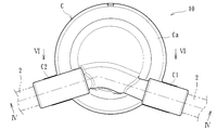
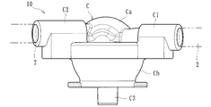
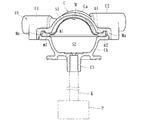
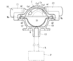
- Front view showing the pressure detector 2 is a cross-sectional view taken along line IV-IV in FIG. 2 (a state where the membrane member is displaced to the liquid phase side).
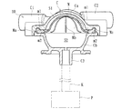
- 2 is a cross-sectional view taken along the line IV-IV in FIG. 2 (a state where the membrane member is displaced to the gas phase side).
- Sectional drawing which shows the same pressure detector (state which the membrane member displaced to the gaseous-phase part) The top view which shows the gaseous-phase part case (state before attaching a hydrophobic membrane) in the same pressure detector
- Sectional drawing which shows the flow path in the same pressure detector Schematic showing the cross section of the hydrophobic membrane in the same pressure detector
- Sectional drawing which shows the same pressure detector (state which the membrane member displaced to the gaseous-phase part) Sectional drawing which shows the flow path in the same pressure detector
- the blood purification apparatus applied to the first embodiment includes a dialysis apparatus for performing dialysis treatment.
- a blood circuit including an arterial blood circuit 1 and a venous blood circuit 2, and an artery A dialyzer 3 (blood purifier) interposed between the side blood circuit 1 and the venous blood circuit 2 to purify blood flowing through the blood circuit, a blood pump 4, and air disposed in the venous blood circuit 2 Trap chamber 5, dialyzer body 6 for supplying dialysate to dialyzer 3 and discharging drainage from dialyzer 3, and physiological saline supply line L3 (replacement) for supplying physiological saline as a replacement fluid to the blood circuit A liquid supply line) and a housing portion 7 containing a physiological saline solution as a replacement liquid.
- An arterial puncture needle a can be connected to the distal end of the arterial blood circuit 1 via a connector, and an iron-type blood pump 4 is disposed in the middle.
- the venous puncture needle b can be connected to the tip thereof via a connector, and the air trap chamber 5 is connected in the middle.
- the air trap chamber 5 can capture bubbles in the liquid and is provided with a filtration network (not shown) so as to capture, for example, a thrombus during blood return.
- the side of the puncture needle that removes blood is referred to as the “arterial side”
- the side of the puncture needle that returns the blood is referred to as the “venous side”.
- “Venous side” is not defined by whether the blood vessel to be punctured is an artery or a vein.
- the blood pump 4 is composed of a squeezing type pump disposed in the arterial blood circuit 1 and is capable of normal rotation and reverse rotation and allows fluid in the blood circuit to flow in the driving direction. That is, a corrugated tube that is softer and larger in diameter than other flexible tubes constituting the arterial blood circuit 1 is connected to the arterial blood circuit 1, and the corrugated tube is connected to the blood pump 4. A roller for squeezing in the liquid feeding direction is provided. When the blood pump 4 is driven in this manner, the roller rotates to squeeze the ironing tube (part of the blood circuit), and the liquid inside can flow in the driving direction (rotating direction of the roller). .
- the blood pump 4 when the blood pump 4 is driven to rotate forward (left rotation in the figure) while the patient is punctured with the arterial puncture needle a and the venous side puncture needle b, the patient's blood passes through the arterial blood circuit 1. After reaching the dialyzer 3, blood purification is performed by the dialyzer 3, and air bubbles are removed in the air trap chamber 5 and returned to the patient's body through the venous blood circuit 2. That is, the blood of the patient is purified by the dialyzer 3 while circulating externally from the tip of the arterial blood circuit 1 to the tip of the venous blood circuit 2 of the blood circuit. Further, when the blood pump 4 is driven in the reverse direction (right rotation in the figure), the blood in the blood circuit (between the distal end of the arterial blood circuit 1 and the position where the blood pump 4 is disposed) can be returned to the patient. .
- the dialyzer 3 is formed with a blood introduction port 3a, a blood outlet port 3b, a dialysate inlet port 3c, and a dialysate outlet port 3d in the casing.
- the blood inlet port 3a includes the arterial blood circuit 1.
- the venous blood circuit 2 is connected to the blood outlet port 3b.
- the dialysate introduction port 3c and the dialysate lead-out port 3d are connected to a dialysate introduction line L1 and a dialysate discharge line L2 extending from the dialyzer body 6, respectively.
- a plurality of hollow fibers are accommodated in the dialyzer 3, the inside of the hollow fibers is used as a blood flow path, and the flow of dialysate is between the hollow fiber outer peripheral surface and the inner peripheral surface of the housing. It is considered a road.
- a hollow fiber is formed in a hollow fiber by forming a large number of minute holes (pores) penetrating the outer peripheral surface and the inner peripheral surface, and impurities or the like in blood are dialyzed through the hollow fiber membrane. It is configured to be able to penetrate into the liquid.
- the dialyzer body 6 is provided with a liquid feeding section such as a dual pump over the dialysate introduction line L1 and the dialysate discharge line L2, and a bypass line that bypasses the liquid feeding section has a dialyzer.
- a water removal pump for removing water from the blood of the patient flowing through the body 3.
- one end of the dialysate introduction line L1 is connected to the dialyzer 3 (dialyte introduction port 3c), and the other end is connected to a dialysate supply device (not shown) for preparing a predetermined concentration of dialysate.
- dialysate discharge line L2 is connected to the dialyzer 3 (dialysate outlet port 3d) and the other end is connected to a drainage unit (not shown), and the dialysate supplied from the dialysate supply device After reaching the dialyzer 3 through the dialysate introduction line L1, it is sent to the drainage section through the dialysate discharge line L2.
- An overflow line is extended from the upper part of the air trap chamber 5, and a clamp part such as a solenoid valve is disposed in the middle of the overflow line. Then, by opening a clamp part such as a solenoid valve, the liquid (priming liquid or the like) flowing in the blood circuit can overflow through the overflow line.
- physiological saline supply line L3 replacement fluid supply line
- the flow path (for example, flexible tube etc.) which can supply the physiological saline (substitution liquid) for replacing with the blood in the blood circuit to the artery side blood circuit 1.
- the other end of the physiological saline supply line L3 is connected to a storage portion 7 (so-called “saline bag”) that stores a predetermined amount of physiological saline, and an air trap chamber 8 is connected in the middle. ing.
- the physiological saline solution supply line L3 is provided with a clamp portion 9 (for example, an electromagnetic valve).
- the clamp portion 9 is provided so as to be able to open and close the physiological saline supply line L3, and can close and open the flow path.
- it may replace with such a clamp part 9 and it is good also as general-purpose means, such as forceps which can block
- the pressure detector 10 is connected to the blood circuit applied to the present embodiment.
- the pressure detector 10 is connected to a position between the dialyzer 3 and the air trap chamber 5 in the venous blood circuit 2 and configured to detect the pressure of blood flowing through the venous blood circuit 2 (blood circuit).
- the pressure detector 10 includes a case C that can be connected to a liquid flow path (in this embodiment, a venous blood circuit 2 (blood circuit)), and a case C A liquid phase part S1 which is attached in C and can be filled with liquid in the flow path (in this embodiment, blood of the venous blood circuit 2 (blood circuit)) and a gas phase part S2 which can be filled with air.
- a membrane member M that is displaceable according to the pressure of the liquid (blood) filled in the liquid phase part S1, and detects the pressure of the gas phase part S2 by the pressure detection sensor P.
- the liquid pressure in the (venous blood circuit 2) can be detected.
- the case C is formed of a hollow molded part obtained by molding a predetermined resin material or the like, and includes a liquid phase part case Ca that constitutes the liquid phase part S1, and a gas phase part case Cb that constitutes the gas phase part S2. It is configured by combining.
- the liquid phase case Ca is integrally formed with an inflow port C1 and an outflow port C2 that can be connected to a liquid flow path and communicated with the liquid phase portion S1, and a gas phase portion case Cb includes a piping portion described later.
- a connection port C3 that can be connected to one end of K and can communicate with the gas phase portion S2 is integrally formed.
- the inflow port C1 and the outflow port C2 may be configured such that the inflow and outflow of liquid are reversed (that is, the liquid flows out through the inflow port C1 and the liquid flows in through the outflow port C2).
- annular holding surface m1 (see FIG. 7) is formed on the outer peripheral edge of the liquid phase case Ca
- annular holding surface m2 (see FIG. 7) is formed on the outer peripheral edge of the gas phase case Cb. 8)
- the outer peripheral portion Ma of the film member M is sandwiched between the sandwiching surface m1 and the sandwiching surface m2.
- the membrane member M can be attached while being sealed.
- the space formed inside the case C is partitioned (defined) by the film member M into the liquid phase part S1 and the gas phase part S2.
- the film member M is made of a diaphragm attached in the case C, and is formed of a flexible material that can be displaced or deformed following the pressure change of the liquid phase part S1 or the gas phase part S2. That is, when the pressure (liquid pressure) of the liquid in the liquid phase part S1 is small, as shown in FIG. 4, the membrane member M is displaced toward the liquid phase part S1 and the capacity of the gas phase part S2 is increased. When the pressure (liquid pressure) of the liquid in the liquid phase part S1 is large, as shown in FIG. 5, the membrane member M is displaced toward the gas phase part S2, and the capacity of the gas phase part S2 decreases. Yes.
- the vapor phase case Cb has an opening Cb1 (see FIG. 8) formed substantially at the center of the bottom surface thereof.
- the opening Cb1 is formed on the inner peripheral surface (bottom surface) of the gas phase part case Cb, and communicates the flow path of the connection port C3 and the gas phase part S2. Air (gas) can flow in or out.
- Air (gas) can flow in or out.
- the connection port C3 is not limited to the one connected to the pipe K, and may be connected to other means that can transmit the pressure of the gas phase section S2 to the pressure sensor P.
- the vapor phase case Cb has a recess Cb4 formed around the opening Cb1 on the bottom surface, and an annular protrusion Cb3 is formed on the outer peripheral side edge of the recess Cb4. ing. Further, as shown in FIG. 8, a plurality of ribs Cb2 projecting radially around the opening Cb1 are formed around the opening Cb1 in the recess Cb4 of the gas phase portion S2, and the flow path R is formed by the rib Cb2. (Holding part) is formed.
- the flow path R (holding portion) according to the present embodiment can hold the inflow or outflow of gas through the opening Cb1 in the process in which the membrane member M is displaced toward the gas phase portion S2, as shown in FIG.
- the space is formed around the opening Cb1 and communicated with the opening Cb1 (a space formed by the recess Cb4). That is, in the process in which the membrane member M is displaced toward the gas phase portion S2, the flow path R is formed in the gap generated by the rib Cb2, and the gas (air in the gas phase section S2) is circulated through the flow path R.
- the flow path R may be formed by a groove formed around the opening Cb1 in the gas phase portion S2.
- the inflow port C1 includes a portion (protrusion) that can be connected to a liquid flow path (blood circuit), and as shown in FIG. 6, the inlet Ca1 (see FIG. 7) of the liquid phase portion S1.
- a liquid (blood) flows, and a connection portion C1b that can be connected to the flow path (blood circuit). That is, the flow path part C1a and the connection part C1b are formed to communicate with each other in the axial direction in the projecting part constituting the inflow port C1, and by connecting a tube constituting the flow path to the connection part C1b, This liquid can be circulated in the flow path part C1a and can be made to flow into the liquid phase part S1 from the inflow port Ca1.
- the inflow port C1 may have a concave shape that connects tubes constituting the flow path.
- the outflow port C2 is composed of a portion (protrusion) that can be connected to a liquid flow path (blood circuit) and, as shown in the figure, the liquid (blood) that has flowed into the liquid phase portion S1. It has a flow path part C2a that flows out from the outflow port Ca2 (see FIG. 7) and a connection part C2b that can be connected to the flow path (blood circuit).
- the flow path part C2a and the connection part C2b are formed to communicate in the axial direction in the protruding part constituting the outflow port C2, and by connecting the tube constituting the flow path to the connection part C2b, the liquid phase
- the liquid that has flowed into the part S1 can be circulated in the flow path part C2a and flowed out to the downstream flow path (blood circuit).
- the outflow port C2 may have a concave shape that connects tubes constituting the flow path.
- the gas phase part S2 is formed in the process in which the opening Cb1 through which the gas can flow in or out according to the displacement of the film member M is formed and the film member M is displaced toward the gas phase part S2. Since the flow passage R (holding portion) that can hold the inflow or outflow of gas through the opening Cb1 is formed, it is possible to secure a necessary measurement range while suppressing an increase in the capacity of the gas phase portion S2. it can.
- the flow path R (holding part) includes a space communicating with the opening Cb1, and allows gas to flow through the flow path R in the process in which the membrane member M is displaced toward the gas phase part S2. As a result, the inflow or outflow of gas through the opening Cb1 is maintained, so that it is possible to reliably prevent the opening Cb1 from being blocked in the process of the film member M being displaced toward the gas phase portion S2.
- the flow passage R is formed by the rib Cb2 (or groove) formed around the opening Cb1 in the gas phase portion S2, it is possible to reliably prevent the opening Cb1 from being blocked with a simple configuration. can do.
- the flow path R may be formed by convex portions (spiral shape or the like) of other shapes instead of the rib Cb2.
- a blood circuit having the effect of the pressure detector 10 as described above can be provided.
- the pressure detector according to this embodiment is applied to the same blood purification apparatus as in the first embodiment.
- the tip of the artery side blood circuit 1 (with the artery side puncture needle a attached) Connected to a position between the blood pump 4 and the site where the blood pump 4 is disposed, so that the pressure of blood flowing through the arterial blood circuit 1 can be detected.
- the pressure detector 10 includes a case C that can be connected to a liquid flow path (corresponding to the venous blood circuit 2 in this embodiment), and a case C
- the liquid phase part S1 that can be filled with the liquid in the flow path (in this embodiment, the blood of the venous blood circuit 2) and the gas phase part S2 that can be filled with air are partitioned, and the liquid phase And a membrane member M that is displaceable according to the pressure of the liquid (blood) filled in the part S1, and detects the pressure in the gas phase part S2 with the pressure detection sensor P, thereby allowing the flow path (venous blood circuit 2).
- symbol is attached
- the flow path R can hold the inflow or outflow of gas through the opening Cb1 in the process in which the membrane member M is displaced toward the gas phase part S2, and
- the recess Cb4 is formed around and a hydrophobic film B (allowable member) that covers the recess Cb4 while including the opening Cb1 and allows gas to pass therethrough.
- the hydrophobic film B is made of a member formed in a film shape that allows gas to pass but blocks liquid from passing, and its outer peripheral edge is welded to the convex part Cb3 formed around the opening Cb1. (For example, ultrasonic welding or the like) is attached.
- the hydrophobic film B includes a first layer B1 obtained by molding a resin material made of PTFE (polytetrafluoroethylene) into a sheet shape (film shape). And a second layer B2 made of a nonwoven fabric made of PEs (polyester) or the like in the thickness direction.
- the thickness including the first layer B1 and the second layer B2 is about 0.1 to 0.5 mm, and the thickness of the first layer B1 (PTFE) is about 1/10 of that. Has been.
- the hydrophobic film B according to the present embodiment uses the second layer B2 as a base material and a first layer B1 formed by sticking PTFE on the surface of the second layer B2 in a sheet shape.
- the first layer B1 only needs to have the property of blocking the passage of liquid while allowing the passage of gas.
- the first layer B1 may be made of an acrylic copolymer or polyethersulfone.
- the flow path R is held by the hydrophobic film B as shown in FIG. 14, and the gas (gas phase part S2) is held in the flow path R.
- Inflow or outflow of gas through the opening Cb1 can be maintained by allowing the flow of air (see the arrow in the figure).
- the hydrophobic membrane B according to the present embodiment blocks the passage of liquid while allowing the passage of gas, but covers the recess Cb4 while including the opening Cb1 and allows the passage of gas. It's enough.
- the gas phase part S2 is formed in the process in which the opening Cb1 through which the gas can flow in or out according to the displacement of the film member M is formed and the film member M is displaced toward the gas phase part S2. Since the flow passage R (holding portion) that can hold the inflow or outflow of gas through the opening Cb1 is formed, it is possible to secure a necessary measurement range while suppressing an increase in the capacity of the gas phase portion S2. it can.
- the flow path R (holding part) includes a space communicating with the opening Cb1, and allows gas to flow through the flow path R in the process in which the membrane member M is displaced toward the gas phase part S2. As a result, the inflow or outflow of gas through the opening Cb1 is maintained, so that it is possible to reliably prevent the opening Cb1 from being blocked in the process of the film member M being displaced toward the gas phase portion S2.
- the flow path R includes a recess Cb4 formed around the opening Cb1 in the gas phase portion S2, and a hydrophobic film B (including the opening Cb1 and covering the recess Cb4 and allowing gas to pass therethrough).
- the permeation area of the gas in the hydrophobic membrane B (permissive member) can be set large, and the resistance when the gas passes can be reduced to suppress the deterioration of the pressure detection accuracy. it can.
- the permission member according to the present embodiment is composed of the hydrophobic film B that blocks the passage of gas while allowing the passage of gas, when the liquid (blood) leaks from the liquid phase portion S2, the leaked liquid Can be prevented from reaching the outside of the gas phase portion S2. Furthermore, according to the present embodiment, a blood circuit having the effect of the pressure detector 10 as described above can be provided.
- the pressure detector according to the present embodiment is applied to the same blood purification apparatus as in the first embodiment.
- the pressure detector includes a dialyzer 3 and an air trap chamber 5 in the venous blood circuit 2. It is connected to a position between them, and is configured to detect the pressure of blood flowing through the venous blood circuit 2 (blood circuit).
- the pressure detector 10 includes a case C that can be connected to a liquid flow path (in this embodiment, the venous blood circuit 2 (blood circuit)), and a case C A liquid phase part S1 which is attached in C and can be filled with liquid in the flow path (in this embodiment, blood of the venous blood circuit 2 (blood circuit)) and a gas phase part S2 which can be filled with air And a membrane member M that is displaceable according to the pressure of the liquid (blood) filled in the liquid phase part S1, and detects the pressure of the gas phase part S2 by the pressure detection sensor P.
- the liquid pressure in the (venous blood circuit 2) can be detected.
- symbol is attached
- the flow path R can hold inflow or outflow of gas through the opening Cb1 in the process in which the film member M is displaced toward the gas phase part S2, and the gas phase part S2 in the film member M is retained. It is formed by ribs Mb (or grooves) formed on the side surface. Specifically, the ribs Mb (grooves) are formed on the surface of the film member M on the gas phase part S2 side, and are integrally formed radially from the center toward the edge. In the process of displacing to the S2 side, as shown in FIG. 18, a flow path R is formed by the gaps formed by the ribs Mb, and the flow of gas (air in the gas phase section S2) in the flow path R (the same figure). By allowing (see the arrow in the middle), inflow or outflow of gas through the opening Cb1 can be maintained.
- the gas phase part S2 is formed in the process in which the opening Cb1 through which the gas can flow in or out according to the displacement of the film member M is formed and the film member M is displaced toward the gas phase part S2. Since the flow passage R (holding portion) that can hold the inflow or outflow of gas through the opening Cb1 is formed, it is possible to secure a necessary measurement range while suppressing an increase in the capacity of the gas phase portion S2. it can.
- the flow path R (holding part) includes a space communicating with the opening Cb1, and allows gas to flow through the flow path R in the process in which the membrane member M is displaced toward the gas phase part S2. As a result, the inflow or outflow of gas through the opening Cb1 is maintained, so that it is possible to reliably prevent the opening Cb1 from being blocked in the process of the film member M being displaced toward the gas phase portion S2.
- the flow passage R since the flow passage R according to the present embodiment is formed by the rib Mb (or groove) formed on the surface of the membrane member M on the gas phase part S2 side, the opening Cb1 can be reliably blocked with a simple configuration. Can be prevented.
- the flow path R may be formed by convex portions (spiral shape or the like) of other shapes instead of the ribs Mb.
- a blood circuit having the effect of the pressure detector 10 as described above can be provided.
- the rib Cb2 in 1st Embodiment was formed in the internal peripheral surface whole region of the gaseous-phase part case Cb, 3rd
- the rib Mb in the embodiment may be formed only in a portion facing the opening Cb1.
- the recess Cb4 in which the rib Cb2 is formed may be covered with the hydrophobic film B of the second embodiment.
- the pressure detector 10 is connected to the venous blood circuit 2, but other positions in the blood circuit (for example, between the tip of the arterial blood circuit 1 and the blood pump 4). Position, position between blood pump 4 and dialyzer 3 in arterial blood circuit 1).
- the blood circuit to which the present pressure detector 10 is connected may be of another form, for example, the air trap chamber 5 is not connected and the present pressure detector 10 is connected instead. Good.
- the pressure detector 10 of the blood circuit in dialysis treatment is applied, but it may be applied as a pressure detector of another blood circuit capable of purifying and treating the patient's blood.
- acetate-free biofiltration AFBF
- continuous slow hemofiltration therapy blood adsorption therapy
- selective blood cell component removal therapy simple plasma exchange therapy
- double membrane filtration plasma exchange therapy plasma adsorption therapy
- the gas phase part is formed with an opening through which the gas can flow in or out according to the displacement of the membrane member, and can hold the gas inflow or outflow through the opening in the process of the film member being displaced toward the gas phase part side. If it is a pressure detector in which the portion is formed, it can be applied to other forms and uses.
Landscapes
- Health & Medical Sciences (AREA)
- Heart & Thoracic Surgery (AREA)
- Vascular Medicine (AREA)
- General Physics & Mathematics (AREA)
- Physics & Mathematics (AREA)
- Life Sciences & Earth Sciences (AREA)
- Veterinary Medicine (AREA)
- Hematology (AREA)
- Anesthesiology (AREA)
- Animal Behavior & Ethology (AREA)
- General Health & Medical Sciences (AREA)
- Public Health (AREA)
- Biomedical Technology (AREA)
- Engineering & Computer Science (AREA)
- Cardiology (AREA)
- Urology & Nephrology (AREA)
- Emergency Medicine (AREA)
- External Artificial Organs (AREA)
- Measuring Fluid Pressure (AREA)
Abstract
La présente invention concerne un détecteur de pression qui comporte : un boîtier pouvant être relié à un passage d'écoulement pour un liquide ; et un élément de membrane pour séparer une section de phase liquide qui est montée à l'intérieur du boîtier et qui peut être remplie du liquide situé dans le passage d'écoulement, et une section de phase gazeuse qui peut être remplie de gaz, l'élément de membrane pouvant être déplacé en fonction de la pression du liquide qui a été introduit dans la section de phase liquide. Le détecteur de pression détecte la pression du liquide dans le passage d'écoulement par détection de la pression de la section de phase gazeuse. Le détecteur de pression est caractérisé en ce que la section de phase gazeuse a, formée dans celle-ci, une ouverture dans laquelle ou à partir de laquelle du gaz peut s'écouler selon le déplacement de l'élément de membrane, et la section de phase gazeuse a, formée sur celle-ci, une section de maintien qui peut maintenir l'entrée ou la sortie de gaz à travers l'ouverture pendant le déplacement de l'élément de membrane vers la section de phase gazeuse.
Priority Applications (3)
| Application Number | Priority Date | Filing Date | Title |
|---|---|---|---|
| EP19802757.5A EP3744364B1 (fr) | 2018-05-16 | 2019-05-15 | Détecteur de pression |
| CN201980032037.3A CN112218667B (zh) | 2018-05-16 | 2019-05-15 | 压力检测器 |
| US17/093,825 US11931500B2 (en) | 2018-05-16 | 2020-11-10 | Pressure detector |
Applications Claiming Priority (2)
| Application Number | Priority Date | Filing Date | Title |
|---|---|---|---|
| JP2018-094465 | 2018-05-16 | ||
| JP2018094465A JP6639559B2 (ja) | 2018-05-16 | 2018-05-16 | 圧力検出器 |
Related Child Applications (1)
| Application Number | Title | Priority Date | Filing Date |
|---|---|---|---|
| US17/093,825 Continuation US11931500B2 (en) | 2018-05-16 | 2020-11-10 | Pressure detector |
Publications (1)
| Publication Number | Publication Date |
|---|---|
| WO2019221205A1 true WO2019221205A1 (fr) | 2019-11-21 |
Family
ID=68540272
Family Applications (1)
| Application Number | Title | Priority Date | Filing Date |
|---|---|---|---|
| PCT/JP2019/019396 Ceased WO2019221205A1 (fr) | 2018-05-16 | 2019-05-15 | Détecteur de pression |
Country Status (5)
| Country | Link |
|---|---|
| US (1) | US11931500B2 (fr) |
| EP (1) | EP3744364B1 (fr) |
| JP (1) | JP6639559B2 (fr) |
| CN (1) | CN112218667B (fr) |
| WO (1) | WO2019221205A1 (fr) |
Cited By (6)
| Publication number | Priority date | Publication date | Assignee | Title |
|---|---|---|---|---|
| US11478885B2 (en) | 2018-06-22 | 2022-10-25 | Nikkiso Company Limited | Method and apparatus of manufacturing medical device |
| US11872334B2 (en) | 2018-05-16 | 2024-01-16 | Nikkiso Company Limited | Pressure detector |
| US11931500B2 (en) | 2018-05-16 | 2024-03-19 | Nikkiso Company Limited | Pressure detector |
| US11931499B2 (en) | 2018-05-16 | 2024-03-19 | Nikkiso Company Limited | Pressure detector |
| US12280194B2 (en) | 2018-05-16 | 2025-04-22 | Nikkiso Company Limited | Pressure detector |
| US12324878B2 (en) | 2018-06-22 | 2025-06-10 | Nikkiso Company Limited | Medical device and method of manufacturing the same |
Families Citing this family (1)
| Publication number | Priority date | Publication date | Assignee | Title |
|---|---|---|---|---|
| US20250057431A1 (en) * | 2023-08-18 | 2025-02-20 | Vikas Raghove | Device for Indicating Pressure of Fluids |
Citations (6)
| Publication number | Priority date | Publication date | Assignee | Title |
|---|---|---|---|---|
| JPH0924026A (ja) * | 1995-07-10 | 1997-01-28 | Otsuka Pharmaceut Factory Inc | 血液回路の圧力測定装置 |
| WO2007040223A1 (fr) * | 2005-10-03 | 2007-04-12 | Jms Co., Ltd. | Réservoir de stockage de sang de type fermé et système de circulation sanguine extracorporel utilisant ledit réservoir |
| JP2008051663A (ja) * | 2006-08-24 | 2008-03-06 | Asahi Kasei Kuraray Medical Co Ltd | 圧力センサ |
| JP2009533154A (ja) * | 2006-04-14 | 2009-09-17 | デカ・プロダクツ・リミテッド・パートナーシップ | 流体圧送、熱交換、熱検知および伝導率検知用システム、器具および方法 |
| JP2014204779A (ja) * | 2013-04-11 | 2014-10-30 | 日機装株式会社 | トランスデューサ保護フィルタ |
| JP2017106812A (ja) * | 2015-12-10 | 2017-06-15 | アズビル株式会社 | 圧力センサチップ |
Family Cites Families (33)
| Publication number | Priority date | Publication date | Assignee | Title |
|---|---|---|---|---|
| FR2346238A1 (fr) | 1976-04-02 | 1977-10-28 | Rhone Poulenc Ind | Reservoir notamment pour liquide biologique |
| US4427470A (en) | 1981-09-01 | 1984-01-24 | University Of Utah | Vacuum molding technique for manufacturing a ventricular assist device |
| JP2582134B2 (ja) | 1988-03-03 | 1997-02-19 | 株式会社 大協精工 | 医薬品用プラスチック容器の栓体及びその製造方法 |
| SE464913B (sv) | 1988-03-03 | 1991-07-01 | Gambro Ab | Anordning foer tryckoeverfoering |
| US4908493A (en) | 1988-05-31 | 1990-03-13 | Midwest Research Institute | Method and apparatus for optimizing the efficiency and quality of laser material processing |
| US5221271A (en) | 1991-08-15 | 1993-06-22 | Medex, Inc. | Sample site with flow directors |
| US6392208B1 (en) | 1999-08-06 | 2002-05-21 | Watlow Polymer Technologies | Electrofusing of thermoplastic heating elements and elements made thereby |
| US6820490B2 (en) | 2001-10-16 | 2004-11-23 | Neomedix Corporation | Systems and methods for measuring pressure |
| EP1658869A1 (fr) | 2004-11-17 | 2006-05-24 | Fresenius Medical Care Deutschland GmbH | Membrane, boîtier d'un capteur de pression et capteur de pression |
| JP4488981B2 (ja) | 2005-08-23 | 2010-06-23 | 日本シャーウッド株式会社 | 取出し具及び医療用縫合具セット |
| US8092414B2 (en) | 2005-11-09 | 2012-01-10 | Nxstage Medical, Inc. | Diaphragm pressure pod for medical fluids |
| WO2007123156A1 (fr) | 2006-04-19 | 2007-11-01 | Asahi Kasei Kuraray Medical Co., Ltd. | Capteur de pression pour circuit de circulation extracorporelle |
| JP5141004B2 (ja) | 2006-12-01 | 2013-02-13 | 株式会社ジェイ・エム・エス | 状態検知装置 |
| CA2681912C (fr) | 2007-02-27 | 2015-09-29 | Deka Products Limited Partnership | Systemes et procedes d'hemodialyse |
| KR101467006B1 (ko) * | 2007-05-15 | 2014-12-01 | 감브로 룬디아 아베 | 압력 감지 장치 및 연결 구조에서의 압력 감지 장치의 사용 |
| ITMO20080083A1 (it) * | 2008-03-21 | 2009-09-22 | Lucomed Spa | Dispositivo di raccordo trasduttore-protettore, particolarmente per linee biomedicali di emodialisi |
| JP5469515B2 (ja) | 2010-04-09 | 2014-04-16 | 内外化成株式会社 | 医療用キャップ |
| US20140052009A1 (en) | 2012-08-15 | 2014-02-20 | Acist Medical Systems, Inc. | Monitoring blood pressure in a medical injection system |
| EP2931334B1 (fr) | 2012-12-14 | 2017-08-09 | Gambro Lundia AB | Repositionnement de diaphragme pour une capsule de pression à l'aide d'une détection de position |
| CN104363936B (zh) * | 2012-12-20 | 2017-04-05 | 甘布罗伦迪亚股份公司 | 用于压力测量装置的基于目标体积的膜复位 |
| JP5826815B2 (ja) | 2013-12-11 | 2015-12-02 | 日機装株式会社 | 混注部材 |
| US8960010B1 (en) | 2013-12-23 | 2015-02-24 | Fresenius Medical Care Holdings, Inc. | Automatic detection and adjustment of a pressure pod diaphragm |
| CA2957067C (fr) | 2014-09-26 | 2019-02-19 | Fresenius Medical Care Holdings, Inc. | Dispositif de sortie de pression pour machine d'hemodialyse extracorporelle |
| JP6517023B2 (ja) | 2015-01-23 | 2019-05-22 | 日機装株式会社 | 血液浄化装置 |
| JP6685089B2 (ja) | 2015-06-01 | 2020-04-22 | 日機装株式会社 | 医療用液圧検出装置 |
| EP3325931B1 (fr) * | 2015-07-20 | 2020-10-28 | Haemonetics Corporation | Système et procédé pour mesurer la pression d'un écoulement de fluide |
| DE102017119708A1 (de) | 2017-08-28 | 2019-02-28 | Kautex Textron Gmbh & Co. Kg | Flüssigkeitsbehälter für ein Kraftfahrzeug und Verfahren zum Herstellen eines Flüssigkeitsbehälters |
| JP7119328B2 (ja) | 2017-10-05 | 2022-08-17 | ニプロ株式会社 | 圧力測定用チャンバ |
| JP6637108B2 (ja) | 2018-05-16 | 2020-01-29 | 日機装株式会社 | 圧力検出器 |
| JP6639559B2 (ja) | 2018-05-16 | 2020-02-05 | 日機装株式会社 | 圧力検出器 |
| JP6637107B2 (ja) | 2018-05-16 | 2020-01-29 | 日機装株式会社 | 圧力検出器 |
| JP7030610B2 (ja) | 2018-05-16 | 2022-03-07 | 日機装株式会社 | 圧力検出器 |
| JP6564914B1 (ja) | 2018-06-22 | 2019-08-21 | 日機装株式会社 | 医療器具及びその製造方法 |
-
2018
- 2018-05-16 JP JP2018094465A patent/JP6639559B2/ja active Active
-
2019
- 2019-05-15 CN CN201980032037.3A patent/CN112218667B/zh active Active
- 2019-05-15 WO PCT/JP2019/019396 patent/WO2019221205A1/fr not_active Ceased
- 2019-05-15 EP EP19802757.5A patent/EP3744364B1/fr active Active
-
2020
- 2020-11-10 US US17/093,825 patent/US11931500B2/en active Active
Patent Citations (6)
| Publication number | Priority date | Publication date | Assignee | Title |
|---|---|---|---|---|
| JPH0924026A (ja) * | 1995-07-10 | 1997-01-28 | Otsuka Pharmaceut Factory Inc | 血液回路の圧力測定装置 |
| WO2007040223A1 (fr) * | 2005-10-03 | 2007-04-12 | Jms Co., Ltd. | Réservoir de stockage de sang de type fermé et système de circulation sanguine extracorporel utilisant ledit réservoir |
| JP2009533154A (ja) * | 2006-04-14 | 2009-09-17 | デカ・プロダクツ・リミテッド・パートナーシップ | 流体圧送、熱交換、熱検知および伝導率検知用システム、器具および方法 |
| JP2008051663A (ja) * | 2006-08-24 | 2008-03-06 | Asahi Kasei Kuraray Medical Co Ltd | 圧力センサ |
| JP2014204779A (ja) * | 2013-04-11 | 2014-10-30 | 日機装株式会社 | トランスデューサ保護フィルタ |
| JP2017106812A (ja) * | 2015-12-10 | 2017-06-15 | アズビル株式会社 | 圧力センサチップ |
Cited By (6)
| Publication number | Priority date | Publication date | Assignee | Title |
|---|---|---|---|---|
| US11872334B2 (en) | 2018-05-16 | 2024-01-16 | Nikkiso Company Limited | Pressure detector |
| US11931500B2 (en) | 2018-05-16 | 2024-03-19 | Nikkiso Company Limited | Pressure detector |
| US11931499B2 (en) | 2018-05-16 | 2024-03-19 | Nikkiso Company Limited | Pressure detector |
| US12280194B2 (en) | 2018-05-16 | 2025-04-22 | Nikkiso Company Limited | Pressure detector |
| US11478885B2 (en) | 2018-06-22 | 2022-10-25 | Nikkiso Company Limited | Method and apparatus of manufacturing medical device |
| US12324878B2 (en) | 2018-06-22 | 2025-06-10 | Nikkiso Company Limited | Medical device and method of manufacturing the same |
Also Published As
| Publication number | Publication date |
|---|---|
| US11931500B2 (en) | 2024-03-19 |
| EP3744364A4 (fr) | 2021-05-19 |
| US20210052797A1 (en) | 2021-02-25 |
| JP6639559B2 (ja) | 2020-02-05 |
| JP2019198456A (ja) | 2019-11-21 |
| CN112218667B (zh) | 2024-02-02 |
| EP3744364A1 (fr) | 2020-12-02 |
| EP3744364B1 (fr) | 2024-04-03 |
| CN112218667A (zh) | 2021-01-12 |
Similar Documents
| Publication | Publication Date | Title |
|---|---|---|
| JP6639559B2 (ja) | 圧力検出器 | |
| JP6637108B2 (ja) | 圧力検出器 | |
| JP7030610B2 (ja) | 圧力検出器 | |
| US11931499B2 (en) | Pressure detector | |
| JP6564914B1 (ja) | 医療器具及びその製造方法 | |
| CN101668555B (zh) | 压力传感装置及其在连接结构中的应用 | |
| JP6694475B2 (ja) | 医療器具の製造方法及び製造装置 | |
| JP7033578B2 (ja) | 圧力検出器 |
Legal Events
| Date | Code | Title | Description |
|---|---|---|---|
| 121 | Ep: the epo has been informed by wipo that ep was designated in this application |
Ref document number: 19802757 Country of ref document: EP Kind code of ref document: A1 |
|
| ENP | Entry into the national phase |
Ref document number: 2019802757 Country of ref document: EP Effective date: 20200827 |
|
| NENP | Non-entry into the national phase |
Ref country code: DE |