WO2019225137A1 - 画像処理装置、表示装置、画像処理方法 - Google Patents
画像処理装置、表示装置、画像処理方法 Download PDFInfo
- Publication number
- WO2019225137A1 WO2019225137A1 PCT/JP2019/012182 JP2019012182W WO2019225137A1 WO 2019225137 A1 WO2019225137 A1 WO 2019225137A1 JP 2019012182 W JP2019012182 W JP 2019012182W WO 2019225137 A1 WO2019225137 A1 WO 2019225137A1
- Authority
- WO
- WIPO (PCT)
- Prior art keywords
- image signal
- image
- liquid crystal
- crystal cell
- value
- Prior art date
- Legal status (The legal status is an assumption and is not a legal conclusion. Google has not performed a legal analysis and makes no representation as to the accuracy of the status listed.)
- Ceased
Links
Images



Classifications
-
- G—PHYSICS
- G09—EDUCATION; CRYPTOGRAPHY; DISPLAY; ADVERTISING; SEALS
- G09G—ARRANGEMENTS OR CIRCUITS FOR CONTROL OF INDICATING DEVICES USING STATIC MEANS TO PRESENT VARIABLE INFORMATION
- G09G3/00—Control arrangements or circuits, of interest only in connection with visual indicators other than cathode-ray tubes
- G09G3/20—Control arrangements or circuits, of interest only in connection with visual indicators other than cathode-ray tubes for presentation of an assembly of a number of characters, e.g. a page, by composing the assembly by combination of individual elements arranged in a matrix no fixed position being assigned to or needed to be assigned to the individual characters or partial characters
- G09G3/34—Control arrangements or circuits, of interest only in connection with visual indicators other than cathode-ray tubes for presentation of an assembly of a number of characters, e.g. a page, by composing the assembly by combination of individual elements arranged in a matrix no fixed position being assigned to or needed to be assigned to the individual characters or partial characters by control of light from an independent source
- G09G3/3406—Control of illumination source
- G09G3/342—Control of illumination source using several illumination sources separately controlled corresponding to different display panel areas, e.g. along one dimension such as lines
- G09G3/3426—Control of illumination source using several illumination sources separately controlled corresponding to different display panel areas, e.g. along one dimension such as lines the different display panel areas being distributed in two dimensions, e.g. matrix
-
- G—PHYSICS
- G09—EDUCATION; CRYPTOGRAPHY; DISPLAY; ADVERTISING; SEALS
- G09G—ARRANGEMENTS OR CIRCUITS FOR CONTROL OF INDICATING DEVICES USING STATIC MEANS TO PRESENT VARIABLE INFORMATION
- G09G3/00—Control arrangements or circuits, of interest only in connection with visual indicators other than cathode-ray tubes
- G09G3/20—Control arrangements or circuits, of interest only in connection with visual indicators other than cathode-ray tubes for presentation of an assembly of a number of characters, e.g. a page, by composing the assembly by combination of individual elements arranged in a matrix no fixed position being assigned to or needed to be assigned to the individual characters or partial characters
- G09G3/34—Control arrangements or circuits, of interest only in connection with visual indicators other than cathode-ray tubes for presentation of an assembly of a number of characters, e.g. a page, by composing the assembly by combination of individual elements arranged in a matrix no fixed position being assigned to or needed to be assigned to the individual characters or partial characters by control of light from an independent source
- G09G3/36—Control arrangements or circuits, of interest only in connection with visual indicators other than cathode-ray tubes for presentation of an assembly of a number of characters, e.g. a page, by composing the assembly by combination of individual elements arranged in a matrix no fixed position being assigned to or needed to be assigned to the individual characters or partial characters by control of light from an independent source using liquid crystals
- G09G3/3607—Control arrangements or circuits, of interest only in connection with visual indicators other than cathode-ray tubes for presentation of an assembly of a number of characters, e.g. a page, by composing the assembly by combination of individual elements arranged in a matrix no fixed position being assigned to or needed to be assigned to the individual characters or partial characters by control of light from an independent source using liquid crystals for displaying colours or for displaying grey scales with a specific pixel layout, e.g. using sub-pixels
-
- G—PHYSICS
- G02—OPTICS
- G02F—OPTICAL DEVICES OR ARRANGEMENTS FOR THE CONTROL OF LIGHT BY MODIFICATION OF THE OPTICAL PROPERTIES OF THE MEDIA OF THE ELEMENTS INVOLVED THEREIN; NON-LINEAR OPTICS; FREQUENCY-CHANGING OF LIGHT; OPTICAL LOGIC ELEMENTS; OPTICAL ANALOGUE/DIGITAL CONVERTERS
- G02F1/00—Devices or arrangements for the control of the intensity, colour, phase, polarisation or direction of light arriving from an independent light source, e.g. switching, gating or modulating; Non-linear optics
- G02F1/01—Devices or arrangements for the control of the intensity, colour, phase, polarisation or direction of light arriving from an independent light source, e.g. switching, gating or modulating; Non-linear optics for the control of the intensity, phase, polarisation or colour
- G02F1/13—Devices or arrangements for the control of the intensity, colour, phase, polarisation or direction of light arriving from an independent light source, e.g. switching, gating or modulating; Non-linear optics for the control of the intensity, phase, polarisation or colour based on liquid crystals, e.g. single liquid crystal display cells
- G02F1/133—Constructional arrangements; Operation of liquid crystal cells; Circuit arrangements
-
- G—PHYSICS
- G02—OPTICS
- G02F—OPTICAL DEVICES OR ARRANGEMENTS FOR THE CONTROL OF LIGHT BY MODIFICATION OF THE OPTICAL PROPERTIES OF THE MEDIA OF THE ELEMENTS INVOLVED THEREIN; NON-LINEAR OPTICS; FREQUENCY-CHANGING OF LIGHT; OPTICAL LOGIC ELEMENTS; OPTICAL ANALOGUE/DIGITAL CONVERTERS
- G02F1/00—Devices or arrangements for the control of the intensity, colour, phase, polarisation or direction of light arriving from an independent light source, e.g. switching, gating or modulating; Non-linear optics
- G02F1/01—Devices or arrangements for the control of the intensity, colour, phase, polarisation or direction of light arriving from an independent light source, e.g. switching, gating or modulating; Non-linear optics for the control of the intensity, phase, polarisation or colour
- G02F1/13—Devices or arrangements for the control of the intensity, colour, phase, polarisation or direction of light arriving from an independent light source, e.g. switching, gating or modulating; Non-linear optics for the control of the intensity, phase, polarisation or colour based on liquid crystals, e.g. single liquid crystal display cells
- G02F1/133—Constructional arrangements; Operation of liquid crystal cells; Circuit arrangements
- G02F1/1333—Constructional arrangements; Manufacturing methods
- G02F1/1347—Arrangement of liquid crystal layers or cells in which the final condition of one light beam is achieved by the addition of the effects of two or more layers or cells
-
- G—PHYSICS
- G09—EDUCATION; CRYPTOGRAPHY; DISPLAY; ADVERTISING; SEALS
- G09G—ARRANGEMENTS OR CIRCUITS FOR CONTROL OF INDICATING DEVICES USING STATIC MEANS TO PRESENT VARIABLE INFORMATION
- G09G3/00—Control arrangements or circuits, of interest only in connection with visual indicators other than cathode-ray tubes
- G09G3/20—Control arrangements or circuits, of interest only in connection with visual indicators other than cathode-ray tubes for presentation of an assembly of a number of characters, e.g. a page, by composing the assembly by combination of individual elements arranged in a matrix no fixed position being assigned to or needed to be assigned to the individual characters or partial characters
-
- G—PHYSICS
- G09—EDUCATION; CRYPTOGRAPHY; DISPLAY; ADVERTISING; SEALS
- G09G—ARRANGEMENTS OR CIRCUITS FOR CONTROL OF INDICATING DEVICES USING STATIC MEANS TO PRESENT VARIABLE INFORMATION
- G09G3/00—Control arrangements or circuits, of interest only in connection with visual indicators other than cathode-ray tubes
- G09G3/20—Control arrangements or circuits, of interest only in connection with visual indicators other than cathode-ray tubes for presentation of an assembly of a number of characters, e.g. a page, by composing the assembly by combination of individual elements arranged in a matrix no fixed position being assigned to or needed to be assigned to the individual characters or partial characters
- G09G3/34—Control arrangements or circuits, of interest only in connection with visual indicators other than cathode-ray tubes for presentation of an assembly of a number of characters, e.g. a page, by composing the assembly by combination of individual elements arranged in a matrix no fixed position being assigned to or needed to be assigned to the individual characters or partial characters by control of light from an independent source
- G09G3/36—Control arrangements or circuits, of interest only in connection with visual indicators other than cathode-ray tubes for presentation of an assembly of a number of characters, e.g. a page, by composing the assembly by combination of individual elements arranged in a matrix no fixed position being assigned to or needed to be assigned to the individual characters or partial characters by control of light from an independent source using liquid crystals
-
- G—PHYSICS
- G09—EDUCATION; CRYPTOGRAPHY; DISPLAY; ADVERTISING; SEALS
- G09G—ARRANGEMENTS OR CIRCUITS FOR CONTROL OF INDICATING DEVICES USING STATIC MEANS TO PRESENT VARIABLE INFORMATION
- G09G2300/00—Aspects of the constitution of display devices
- G09G2300/02—Composition of display devices
- G09G2300/023—Display panel composed of stacked panels
-
- G—PHYSICS
- G09—EDUCATION; CRYPTOGRAPHY; DISPLAY; ADVERTISING; SEALS
- G09G—ARRANGEMENTS OR CIRCUITS FOR CONTROL OF INDICATING DEVICES USING STATIC MEANS TO PRESENT VARIABLE INFORMATION
- G09G2320/00—Control of display operating conditions
- G09G2320/02—Improving the quality of display appearance
- G09G2320/0233—Improving the luminance or brightness uniformity across the screen
-
- G—PHYSICS
- G09—EDUCATION; CRYPTOGRAPHY; DISPLAY; ADVERTISING; SEALS
- G09G—ARRANGEMENTS OR CIRCUITS FOR CONTROL OF INDICATING DEVICES USING STATIC MEANS TO PRESENT VARIABLE INFORMATION
- G09G2320/00—Control of display operating conditions
- G09G2320/02—Improving the quality of display appearance
- G09G2320/0271—Adjustment of the gradation levels within the range of the gradation scale, e.g. by redistribution or clipping
-
- G—PHYSICS
- G09—EDUCATION; CRYPTOGRAPHY; DISPLAY; ADVERTISING; SEALS
- G09G—ARRANGEMENTS OR CIRCUITS FOR CONTROL OF INDICATING DEVICES USING STATIC MEANS TO PRESENT VARIABLE INFORMATION
- G09G2320/00—Control of display operating conditions
- G09G2320/02—Improving the quality of display appearance
- G09G2320/0271—Adjustment of the gradation levels within the range of the gradation scale, e.g. by redistribution or clipping
- G09G2320/0276—Adjustment of the gradation levels within the range of the gradation scale, e.g. by redistribution or clipping for the purpose of adaptation to the characteristics of a display device, i.e. gamma correction
-
- G—PHYSICS
- G09—EDUCATION; CRYPTOGRAPHY; DISPLAY; ADVERTISING; SEALS
- G09G—ARRANGEMENTS OR CIRCUITS FOR CONTROL OF INDICATING DEVICES USING STATIC MEANS TO PRESENT VARIABLE INFORMATION
- G09G2320/00—Control of display operating conditions
- G09G2320/06—Adjustment of display parameters
- G09G2320/0626—Adjustment of display parameters for control of overall brightness
-
- G—PHYSICS
- G09—EDUCATION; CRYPTOGRAPHY; DISPLAY; ADVERTISING; SEALS
- G09G—ARRANGEMENTS OR CIRCUITS FOR CONTROL OF INDICATING DEVICES USING STATIC MEANS TO PRESENT VARIABLE INFORMATION
- G09G2320/00—Control of display operating conditions
- G09G2320/06—Adjustment of display parameters
- G09G2320/0626—Adjustment of display parameters for control of overall brightness
- G09G2320/0646—Modulation of illumination source brightness and image signal correlated to each other
-
- G—PHYSICS
- G09—EDUCATION; CRYPTOGRAPHY; DISPLAY; ADVERTISING; SEALS
- G09G—ARRANGEMENTS OR CIRCUITS FOR CONTROL OF INDICATING DEVICES USING STATIC MEANS TO PRESENT VARIABLE INFORMATION
- G09G2320/00—Control of display operating conditions
- G09G2320/10—Special adaptations of display systems for operation with variable images
- G09G2320/103—Detection of image changes, e.g. determination of an index representative of the image change
-
- G—PHYSICS
- G09—EDUCATION; CRYPTOGRAPHY; DISPLAY; ADVERTISING; SEALS
- G09G—ARRANGEMENTS OR CIRCUITS FOR CONTROL OF INDICATING DEVICES USING STATIC MEANS TO PRESENT VARIABLE INFORMATION
- G09G2320/00—Control of display operating conditions
- G09G2320/10—Special adaptations of display systems for operation with variable images
- G09G2320/106—Determination of movement vectors or equivalent parameters within the image
-
- G—PHYSICS
- G09—EDUCATION; CRYPTOGRAPHY; DISPLAY; ADVERTISING; SEALS
- G09G—ARRANGEMENTS OR CIRCUITS FOR CONTROL OF INDICATING DEVICES USING STATIC MEANS TO PRESENT VARIABLE INFORMATION
- G09G2340/00—Aspects of display data processing
-
- G—PHYSICS
- G09—EDUCATION; CRYPTOGRAPHY; DISPLAY; ADVERTISING; SEALS
- G09G—ARRANGEMENTS OR CIRCUITS FOR CONTROL OF INDICATING DEVICES USING STATIC MEANS TO PRESENT VARIABLE INFORMATION
- G09G2360/00—Aspects of the architecture of display systems
- G09G2360/14—Detecting light within display terminals, e.g. using a single or a plurality of photosensors
- G09G2360/144—Detecting light within display terminals, e.g. using a single or a plurality of photosensors the light being ambient light
-
- G—PHYSICS
- G09—EDUCATION; CRYPTOGRAPHY; DISPLAY; ADVERTISING; SEALS
- G09G—ARRANGEMENTS OR CIRCUITS FOR CONTROL OF INDICATING DEVICES USING STATIC MEANS TO PRESENT VARIABLE INFORMATION
- G09G2360/00—Aspects of the architecture of display systems
- G09G2360/16—Calculation or use of calculated indices related to luminance levels in display data
Definitions
- the present technology relates to an image processing device, a display device, and an image processing method, and more particularly to processing of an image signal for a display panel in which a display image is generated by light passing through a rear liquid crystal cell and a front liquid crystal cell.
- the display images of two liquid crystals appear double due to parallax when observed from an oblique direction.
- a signal input to the rear liquid crystal cell is gamma-converted to a gamma value of 1 or less, thereby saturating the rear liquid crystal cell to 100% with a certain gradation or more, or a signal input to the rear liquid crystal cell is planar.
- a filter process that spreads in the direction is performed to reduce image shift due to parallax.
- the white spot displayed on the rear liquid crystal cell is widened by the above filtering process, but the signal is displayed on the rear liquid crystal cell due to the leakage light of the front liquid crystal cell.
- the image may be seen through, and the area around the white spot may appear to be shining thinly, resulting in a reduction in image quality.
- the white spot spread on the rear liquid crystal cell side becomes brighter due to the gamma conversion process, the leakage light increases and the image quality further deteriorates.
- the present technology aims to reduce such image quality degradation when a dual liquid crystal cell type display device is used.
- An image processing apparatus performs gradation value conversion on an input image signal that is an image signal for a display panel in which a display image is generated by light that has passed through a rear liquid crystal cell and a front liquid crystal cell, and performs the conversion on the rear liquid crystal cell.
- a gradation value conversion unit that generates a rear image signal
- a limit processing unit that performs a process of limiting the value of the rear image signal output from the gradation value conversion unit to a limit value.
- An image signal to be processed by this image processing apparatus is an image signal used in a liquid crystal display panel of a dual liquid crystal cell type.
- the image processing apparatus performs image signal processing on each of a front liquid crystal cell and a rear liquid crystal cell of a dual liquid crystal cell type liquid crystal display panel. In this case, limit processing is performed on the rear image signal generated by gradation value conversion.
- the image processing apparatus includes a maximum value detection unit that detects the maximum value of the input image signal, and the limit processing unit sets the limit value to the maximum value detected by the maximum value detection unit. It is conceivable to use a value based on this. That is, the maximum value of the input image signal is detected, and the limit value is a value that changes as a value based on the maximum value.
- the limit processing unit may use the maximum value detected by the maximum value detection unit as a limit value. That is, the maximum value of the input signal is used as the limit value as it is.
- the maximum value detection unit detects a maximum value for each of a plurality of areas set in the image, and the limit processing unit detects the maximum value in the area for each area. It is conceivable to perform limit processing using limit values based on the above. That is, one frame image area is divided into a plurality of areas. Then, the maximum value of the input signal is detected for each area, and the limit processing of the rear image signal is performed with the limit value based on the maximum value for each area.
- the above-described image processing apparatus may include a lower limit processing unit that outputs the lower limit value as a maximum value when the maximum value detected by the maximum value detection unit is less than a set lower limit value. It is done. In other words, if the detected maximum value is equal to or greater than the set lower limit value, the detected maximum value is output as it is, but if the detected maximum value is less than the lower limit value, the detected maximum value is set to the lower limit value. Replace with and output.
- the image processing apparatus may include a time filter unit that suppresses the amount of fluctuation in the time axis direction of the maximum value detected by the maximum value detection unit.
- the maximum value of the current frame of the input image signal changes abruptly between the maximum value of the previous frame (in the case of area division, the maximum value of a certain area of the current frame and the maximum value of the corresponding area of all frames). Suppress the amount of fluctuations.
- the image processing apparatus includes a scene change detection unit that detects a scene change with respect to an input image signal, and the time filter unit can change a filter operation when a scene change is detected. Conceivable. For example, the scene change detection unit detects whether or not the scene as the image content has changed by comparing the current frame with the previous frame. The time filter unit switches the filter characteristics and switches on / off of the filter process in response to the scene change being detected.
- the lower limit processing unit when the maximum value detected by the maximum value detection unit is less than a set lower limit value, a lower limit processing unit that uses the maximum value as the lower limit value, and an input image signal A moving image detecting unit that detects whether or not the image is a moving image is provided, and the lower limit processing unit may consider that the lower limit value is different depending on whether the input image signal is a moving image or not. For example, the lower limit value in the lower limit process is made different between when the input image signal is a moving image and when it is a still image.
- the image processing apparatus may include a spatial filter unit that suppresses the maximum amount of variation in the spatial direction for each of a plurality of areas set in the image.
- the filter processing is performed so that the maximum value in each area does not change suddenly in the spatial direction (the direction of the image plane in which a plurality of areas are adjacent).
- the gradation value conversion unit may perform gamma conversion with a gamma value smaller than 1.
- Gamma conversion with a gamma value smaller than 1 is performed in order to perform good gradation expression with the front image and rear image combined. In this case, limit processing is performed.
- a spatial processing unit that performs spatial filter processing on the rear image signal to widen a transmission pixel range of the image in the rear liquid crystal cell more than the image of the front liquid crystal cell, It is possible to prepare. That is, spatial filter processing is performed so as to blur the rear image. Specifically, a low-pass filter for the rear image signal is used so that the image of the front liquid crystal cell by the front image signal is widened so that the range of pixels transmitted on the rear liquid crystal cell side is widened. Apply processing.
- the image processing apparatus includes a front image generation unit that performs arithmetic processing using the rear image signal on the input image signal and generates a front image signal for the front liquid crystal cell,
- the input image signal is a color image signal
- the gradation value conversion unit performs gradation value conversion on a monochrome image signal converted from the color image signal
- the front image generation unit is a color image signal. It is conceivable to generate a front image signal by dividing the rear image signal processed by the limit processing unit from a certain input image signal. That is, for example, R, G, B gradation values as image signals that are color image signals, the gradation values of the rear image signal after the limit processing are respectively divided, and R, G, B as front image signals are divided. Get the tone value.
- the display device performs gradation value conversion on a display panel in which a display image is generated by light that has passed through a rear liquid crystal cell and a front liquid crystal cell, and an input image signal that is an image signal for the display panel, and A gradation value conversion unit that generates a rear image signal for the rear liquid crystal cell, a limit processing unit that performs a process of limiting the value of the rear image signal output from the gradation value conversion unit to a predetermined limit value, and the input A front image generation unit that performs arithmetic processing using the rear image signal on the image signal to generate a front image signal for the front liquid crystal cell.
- a light source unit for example, a light source unit, a rear liquid crystal cell, a diffusion layer, and a front liquid crystal cell are arranged in this order to constitute a so-called dual liquid crystal cell type liquid crystal display panel.
- Limit processing is performed on the rear image signal for such a liquid crystal display panel of the dual liquid crystal cell type.
- gradation value conversion in the image processing apparatus and processing for limiting to a limit value are performed.
- FIG. 1 shows a configuration of a display device 90 according to the embodiment.
- the display device 90 includes the liquid crystal display panel 1, the image processing device 10, the front liquid crystal cell driving unit 20, and the rear liquid crystal cell driving unit 30.
- the liquid crystal display panel 1 is a dual cell type liquid crystal display panel, and includes a front liquid crystal cell 2, a diffusion layer 4, a rear liquid crystal cell 3, and a backlight 5.
- the rear liquid crystal cell 3, the diffusion layer 4, and the front liquid crystal cell 2 are arranged on the front side of the backlight 5 so as to overlap in this order, and the viewer sees the image displayed from the front side of the front liquid crystal cell 2. It will be.
- Each of the front liquid crystal cell 2 and the rear liquid crystal cell 3 forms one liquid crystal display panel.
- the entire dual liquid crystal cell type display panel is referred to as a liquid crystal display panel 1.
- the image processing apparatus 10 performs signal processing for display on the liquid crystal display panel 1 on the image signal S1 input as a color image signal (for example, a signal in the UHD (Ultra High Definition) format).
- the image processing apparatus 10 includes a display image processing unit 11 and a dual cell image processing unit 12.
- the display image processing unit 11 performs necessary decoding processing, luminance processing, color processing, resolution conversion, and the like on the input image signal S1, and supplies the processed image signal Sig_in to the dual cell image processing unit 12. .
- a color image signal indicating the gradation value of each color of R, G, and B is used.
- the dual cell image processing unit 12 performs processing corresponding to the dual cell type liquid crystal display panel 1. That is, the dual cell image processing unit 12 performs signal processing on the input image signal Sig_in, and generates an image signal for the front liquid crystal cell 2 (front image signal Sig_FR) and an image signal for the rear liquid crystal cell 3 (rear image signal Sig_RE). And output.
- the front image signal Sig_FR is a color image signal including R, G, and B gradation values.
- the rear image signal Sig_RE is a black and white (grayscale) image signal including a gradation value as a grayscale.
- the front image signal Sig_FR output from the image processing apparatus 10 is supplied to the front liquid crystal cell driving unit 20.
- the front liquid crystal cell driving unit 20 drives the front liquid crystal cell 2 based on the front image signal Sig_FR to execute color image display.
- the rear image signal Sig_RE output from the image processing apparatus 10 is supplied to the rear liquid crystal cell driving unit 30.
- the rear liquid crystal cell driving unit 30 drives the rear liquid crystal cell 3 based on the rear image signal Sig_RE to execute monochrome image display.
- the front liquid crystal cell driving unit 20 includes a display control unit 21, a vertical driving unit 22, and a horizontal driving unit 23, and drives the front liquid crystal cell 2 with these configurations.
- the display control unit 21 supplies a control signal to the vertical drive unit 22 based on the front image signal Sig_FR, and also responds to the horizontal drive unit 23 in accordance with the image signals (R, G, and B gradation values). Signal) and control signals are supplied and controlled so as to operate in synchronization with each other.
- the vertical drive unit 22 Based on the control signal supplied from the display control unit 21, the vertical drive unit 22 sequentially selects one horizontal line as a display drive target in the front liquid crystal cell 2.
- the horizontal drive unit 23 generates a pixel voltage for one horizontal line based on the image signal and the control signal supplied from the display control unit 21, and sub-pixels 26 (for one horizontal line selected by the vertical drive unit 22 ( 26R, 26G, 26B).
- each pixel 25 has three sub-pixels 26R, 26G, and 26B.
- the sub-pixel 26R has a red color filter
- the sub-pixel 26G has a green color filter
- the sub-pixel 26B has a blue color filter.
- a pixel voltage is supplied to each of the sub-pixels 26R, 26G, and 26B from the horizontal driving unit 23.
- the sub-pixels 26R, 26G, and 26B change the light transmittance according to the pixel voltage.
- the rear liquid crystal cell driving unit 30 includes a display control unit 31, a vertical driving unit 32, and a horizontal driving unit 33, and drives the rear liquid crystal cell 3 with these configurations.
- the display control unit 31 supplies a control signal to the vertical drive unit 32 based on the rear image signal Sig_RE, and also outputs an image signal to the horizontal drive unit 33 (a signal corresponding to a gradation value as a gray scale). And a control signal is supplied to control them so as to operate in synchronization with each other.
- the vertical drive unit 32 Based on the control signal supplied from the display control unit 31, the vertical drive unit 32 sequentially selects one horizontal line as a display drive target in the front liquid crystal cell 2.
- the horizontal driving unit 33 generates a pixel voltage for one horizontal line based on the image signal and the control signal supplied from the display control unit 31, and supplies the pixel voltage for one horizontal line selected by the vertical driving unit 32. To supply.
- the rear liquid crystal cell 3 has a plurality of pixels 35 arranged in a matrix. Each pixel 35 has three sub-pixels 36. Each sub-pixel 36 does not have a color filter. That is, each sub pixel 26R, 26G, 26B in the front liquid crystal cell 2 has a color filter of a corresponding color, but each sub pixel 36 in the rear liquid crystal cell 3 does not have a color filter.
- the same pixel voltage is supplied from the horizontal drive unit 33 to the three sub-pixels 36 belonging to one pixel 35.
- the sub-pixel 36 changes the light transmittance according to the pixel voltage.
- the pixel 35 of the rear liquid crystal cell 3 may be configured with the above three sub-pixels as one electrode and one pixel of a black matrix.
- each liquid crystal structural element such as TFT, transparent electrode, wiring, and black matrix may have a structure having no sub-pixel.
- one pixel 35 corresponds to three sub-pixels 26R, 26G, and 26B in the front liquid crystal cell 2.
- Such a rear liquid crystal cell 3 can be manufactured by omitting a color filter forming step in a manufacturing process of a general-purpose liquid crystal display panel capable of displaying a color image. Thereby, in the display apparatus 90, development cost and manufacturing cost can be reduced compared with the case where a dedicated product is developed.
- the backlight 5 shown in FIG. 1 emits light based on a backlight control signal (not shown).
- the backlight 5 is disposed on the back side of the rear liquid crystal cell 3.
- the backlight 5 includes a light emitting unit such as an LED (Light Emitting Diode) and emits light.
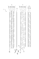
- FIG. 3 shows an arrangement configuration of the liquid crystal display panel 1.
- a backlight 5, a rear liquid crystal cell 3, a diffusion layer 4, and a front liquid crystal cell 2 are arranged in this order, and the upper surface of the front liquid crystal cell 2 in FIG. It has become. That is, the light emitted from the backlight 5 passes through the backlight 5, the rear liquid crystal cell 3, the diffusion layer 4, and the front liquid crystal cell 2 in order, and reaches the viewer.
- the front liquid crystal cell 2 and the rear liquid crystal cell 3 are spaced apart from each other.
- a diffusion layer 4 is disposed in the gap 8 between the front liquid crystal cell 2 and the rear liquid crystal cell 3.
- the front liquid crystal cell 2 and the rear liquid crystal cell 3 are adhered to each other with an adhesive layer without a gap.
- the front liquid crystal cell 2 includes substrates 122 and 124, a liquid crystal layer 123, and polarizing plates 121 and 125.
- the substrates 122 and 124 are made of, for example, a glass substrate, and are disposed so as to face each other.
- a pixel electrode is formed for each sub-pixel 26 on the surface of the substrate 122 on the substrate 124 side, and a pixel voltage is applied by the horizontal drive unit 23 described above.
- An electrode common to the sub-pixels 26 is formed on the surface of the substrate 124 on the substrate 122 side.
- a color filter and a black matrix are formed on the substrate 124.
- the liquid crystal layer 123 is sealed between the substrate 122 and the substrate 124, and the light transmittance changes according to the pixel voltage applied to the pixel electrode of the substrate 122.
- the polarizing plate 121 is attached to the light incident side of the substrate 122, and the polarizing plate 125 is attached to the light emitting side of the substrate 124.
- the transmission axis of the polarizing plate 121 and the transmission axis of the polarizing plate 125 intersect each other.
- the rear liquid crystal cell 3 includes substrates 132 and 134, a liquid crystal layer 133, and polarizing plates 131 and 135.
- the substrates 132 and 134 are made of, for example, a glass substrate and are disposed so as to face each other.
- a pixel electrode is formed for each sub-pixel 26 on the surface of the substrate 132 on the substrate 134 side, and a pixel voltage is applied by the horizontal driving unit 33 described above. Note that a structure without sub-pixels as described above is also conceivable. In that case, a pixel electrode is formed for each pixel 35.
- An electrode common to the sub-pixels 36 is formed on the surface of the substrate 134 on the substrate 132 side.
- a black matrix is formed on the substrate 134.
- the substrate 134 Unlike the substrate 124 of the front liquid crystal cell 2, no color filter is formed on the substrate 134.
- the liquid crystal layer 133 is sealed between the substrate 132 and the substrate 134, and the light transmittance changes according to the pixel voltage applied to the pixel electrode of the substrate 132.
- the polarizing plate 131 is attached to the light incident side of the substrate 132, and the polarizing plate 135 is attached to the light emitting side of the substrate 134.
- the transmission axis of the polarizing plate 131 and the transmission axis of the polarizing plate 135 intersect each other.
- the diffusion layer 4 diffuses light incident from the rear liquid crystal cell 3 side.
- a diffusion film in which beads are randomly distributed on the resin film or in the resin film can be used.
- the diffusion layer 4 is for reducing moire in the display image. That is, since the liquid crystal display panel 1 includes the front liquid crystal cell 2 and the rear liquid crystal cell 3 which are two liquid crystal display panels, the liquid crystal display panel 1 may cause moire in the display image. Therefore, in the liquid crystal display panel 1, the diffusing layer 4 is disposed between the front liquid crystal cell 2 and the rear liquid crystal cell 3, thereby reducing moire and suppressing deterioration in image quality.
- Moire can be effectively suppressed as the diffusion degree (haze value) of the diffusion layer 4 is higher.
- the degree of freedom in designing the inter-panel distance dFR for obtaining a desired image quality can be increased.
- the haze value becomes high, there is a concern about a decrease in luminance. Therefore, it is desirable to reduce the resolution of the rear liquid crystal cell 3 and delete the color filter. Even when the haze value of the diffusion layer 4 is low, for example, the desired image quality can be obtained by disposing the diffusion layer 4 close to the front liquid crystal cell 2.
- the backlight 5 includes a diffusion plate 141 in addition to the light emitting array 42.
- the diffusion plate 141 diffuses the light emitted from the light emitting array 42.
- the light emitting array 42 is configured by arranging LEDs, for example.
- FIG. 4 is a block diagram of the dual cell image processing unit 12
- FIG. 5 is a block diagram showing in detail the interior of the rear image generation unit 51 in FIG.
- the dual cell image processing unit 12 includes an RGB input unit 50, a rear image generation unit 51, a front image generation unit 52, a light amount correction unit 53, panel gamma processing units 54 and 57, adjustment units 55 and 58, A rear output unit 56 and a front output unit 59 are provided.
- the image signal Sig_in from the display image processing unit 11 is input to the RGB input unit 50, and is supplied from the RGB input unit 50 to the rear image generation unit 51.
- the image signal Sig_in is, for example, a signal of 1024 gradations with 10 bits for each of R, G, and B.
- 1024 gradations (10 bits) is merely an example for explanation, and a signal having fewer or more gradations (number of bits) may be used.
- the rear image generation unit 51 generates a rear image signal Sig_RE by processing to be described later.
- the rear image signal Sig_RE is, for example, a signal of W (white) 1024 gradations (10 bits: 0 to 1023).
- the rear image signal Sig_RE is subjected to gamma processing corresponding to the rear liquid crystal cell 3 by the panel gamma processing unit 54 and then subjected to necessary adjustment processing by the adjustment unit 55.
- the rear output unit 56 performs delay adjustment processing, parallelization corresponding to the three sub-pixels 36, and the like, and supplies the rear liquid crystal cell driving unit 30 to the rear liquid crystal cell driving unit 30.
- the rear image signal Sig_RE is a front image signal Sig_FR at three timings corresponding to the three subpixels 26R, 26G, and 26B in the front liquid crystal cell 2. Corresponding output.
- the rear image signal Sig_RE generated by the rear image generation unit 51 is also supplied to the light amount correction unit 53.
- the light amount correction unit 53 multiplies the rear image signal Sig_RE by a light amount correction coefficient kLC for correcting the light amount component incident on the front liquid crystal cell 2 and outputs the result to the front image generation unit 52.
- the light quantity correction coefficient kLC is a fixed value, for example. However, the light quantity correction coefficient kLC may be a variable value. For example, the light amount correction coefficient kLC may be calculated adaptively according to the image.
- the front image generation unit 52 is supplied with an image signal Sig_in.
- the front image generation unit 52 includes a division unit 52a as shown in FIG. 5, and generates a front image signal Sig_FR by dividing the rear image signal Sig_RE from the input image signal Sig_in.
- the front image signal Sig_FR can be displayed according to the luminance of the original image signal Sig_in for each pixel by dividing the luminance by the amount of the rear image signal Sig_RE. For this reason, the front image signal Sig_FR is generated by dividing the rear image signal Sig_RE from the image signal Sig_in.
- the image signal Sig_in is a signal including the gradation values Sig_in (R), Sig_in (G), and Sig_in (B) of R, G, and B. More specifically, the front image signal Sig_FR R, G, and B gradation values Sig_FR (R), Sig_FR (G), and Sig_FR (B) are generated.
- Sig_FR (R) Sig_in (R) / (Sig_RE ⁇ kLC)
- Sig_FR (G) Sig_in (G) / (Sig_RE ⁇ kLC)
- Sig_FR (B) Sig_in (B) / (Sig_RE ⁇ kLC)
- the gradation values Sig_FR (R), Sig_FR (G), and Sig_FR (B) of R, G, and B are signals of, for example, 10 bits and 1024 gradations (0 to 1023).
- the front image signal Sig_FR generated by the front image generation unit 52 is subjected to gamma processing corresponding to the front liquid crystal cell 2 by the panel gamma processing unit 57 shown in FIG.
- the front output unit 59 performs parallelization and the like corresponding to the three sub-pixels 26R, 26G, and 26B, and supplies them to the front liquid crystal cell driving unit 20.
- the rear image generation unit 51 converts the input image signal Sig_in, which is a color image signal, into a gray scale signal (monochrome image signal) Gr by the gray scale conversion unit 70.
- the gray scale signal Gr has a gradation value (0 to 1023) as W (white).
- Such a gray scale signal Gr is supplied to the gradation converting unit 72 and subjected to gradation value conversion.
- the gradation conversion unit 72 includes an LUT (Look Up Table) 73 and a gamma conversion unit 74.
- the gamma conversion unit 74 refers to the LUT 73 with the gradation value of the input grayscale signal Gr as the LUT input signal LUT in, and obtains a corresponding output gradation value (LUT output signal LUTout).
- the output gradation value LUTout is output as a rear image signal Sig_RE.
- the rear image signal Sig_RE is supplied to the limit processing unit 80.
- FIG. 6A shows an example of conversion characteristics in the gradation conversion unit 72. That is, the conversion curve of the LUT 73 as input gradation (horizontal axis) -output gradation (vertical axis) is shown. In this case, the gamma value is set to a value smaller than “1”, and the value after gamma conversion is higher than the value before gamma conversion.
- FIG. 6B shows the light transmittance in the front liquid crystal cell 2 and the rear liquid crystal cell 3.
- the horizontal axis indicates the gradation level of the signal supplied to the front liquid crystal cell 2 and the rear liquid crystal cell 3
- the vertical axis indicates the transmittances L2 and L3.
- the transmittance L2 indicates the transmittance in the front liquid crystal cell 2
- the transmittance L3 indicates the transmittance in the rear liquid crystal cell 3.
- the transmittance L2 changes according to the gradation level in a range where the gradation level is higher than a certain level (for example, a level of about 40 [%]). L2 becomes almost constant. That is, the transmittance L2 of the front liquid crystal cell 2 is not sufficiently lowered in the low gradation range. Therefore, in the liquid crystal display panel 1, the transmittance L3 in the rear liquid crystal cell 3 is constant (100%) in the range where the gradation level is high, and the rear level is in the range where the gradation level is lower than about 40 [%], for example. The transmittance L3 in the liquid crystal cell 3 is changed according to the gradation level.
- a certain level for example, a level of about 40 [%]
- the product Ltotal of the transmittance L2 in the front liquid crystal cell 2 and the transmittance L3 in the rear liquid crystal cell 3 is the same as in the high gradation level range even in the low gradation level range. , And can be changed according to the gradation level. Therefore, in the liquid crystal display panel 1, since the transmittance Ltotal can be lowered in the low gradation range, for example, compared with the case where it is configured using one liquid crystal cell, the contrast can be increased.
- the gradation converting unit 72 performs gamma conversion so that the transmittance L3 shown in FIG. 6B can be realized. The conversion characteristics in this case are as shown in FIG. 6A, for example.
- the output gradation value is set to the maximum gradation value in a range where the input gradation value is higher than a certain gradation value.
- the signal output as the output gradation value LUTout from the gradation conversion unit 72 is the rear image signal Sig_RE.
- the limit processing unit 80 performs processing for limiting the upper limit value of the rear image signal Sig_RE output from the gradation conversion unit 72.
- the limit value in the limit processing unit 80 is determined by the output value from the area max value detection unit 81.
- the area max value detection unit 81 detects and detects the maximum value among the R, G, and B tone values Sig_in (R), Sig_in (G), and Sig_in (B) in the input image signal Sig_in.
- the maximum value is output to the limit processing unit 80. In the example of FIG. 5, this maximum value is the limit value in the limit processing unit 80. Details of the limit processing unit 80 and the area max value detection unit 81 will be described later.
- the spatial processing unit 79 performs processing such as a spatial filter on the rear image signal Sig_RE via the limit processing unit 80. This is a process of spreading like a filter while maintaining the peak gradation of the rear image signal Sig_RE.
- the spatial processing unit 79 performs filter processing using an FIR (Finite Impulse Response) filter.
- This FIR filter functions as a low-pass filter and blurs the image displayed on the rear liquid crystal cell 3.
- the number of taps of the FIR filter is set according to the target value ⁇ of the viewing angle that does not cause a missing image or a double image in the display image.
- FIG. 7 is for explaining the spatial filter processing by the spatial processing unit 79, and shows the gradation (luminance) in each of the liquid crystal cells 2, 3 along with the schematic sectional views of the front liquid crystal cell 2 and the rear liquid crystal cell 3. Yes.
- the front liquid crystal cell 2 displays the display element a11
- the rear liquid crystal cell 3 displays the display element a12 at a position corresponding to the display position of the display element a11 in the front liquid crystal cell 2. Since the display element a12 is blurred by the spatial filter process, the width w12 of the display element a12 is larger than the width w11 of the display element a12.
- the gradation of the display element a11 is constant at the original gradation value of the display element a11 within the transmission range.
- the gradation of the display element a11 has a mountainous distribution as indicated by a solid line.
- the rear image signal Sig_RE is processed so that the transmissive pixel range in the rear liquid crystal cell 3 is wider than that of the front liquid crystal cell 2 and the above-described gradual gradation change occurs and the image is blurred. become.
- FIG. 8A and 8B show schematic sectional views of the front liquid crystal cell 2 and the rear liquid crystal cell 3 and the gradation (luminance) in each of the liquid crystal cells 2 and 3 as in FIG.
- FIG. 8A shows the case where the rear image signal Sig_RE is subjected to the spatial filter processing
- FIG. 8B shows the case where the spatial filter processing is not performed.
- the display element a13 displayed on the rear liquid crystal cell 3 has the same width as the display element a11 displayed on the front liquid crystal cell 2, as shown in FIG. Is also steep.
- the display element a11 is observed in the range C11.
- the range C11 there is a portion where the light transmittance in the front liquid crystal cell 2 is high, but the light transmittance in the rear liquid crystal cell 3 is low. For this reason, a part of the display element a11 may be cut off and visually recognized.
- the light transmittance in the front liquid crystal cell 2 is low, but the light transmittance in the rear liquid crystal cell 3 is high. Then, when the transmittance of the front liquid crystal cell 2 in the range C13 is not sufficiently low, a double image may be generated in the display image.
- the display element a12 displayed on the rear liquid crystal cell 3 is blurred by the spatial filter processing, the display element a12 displayed on the front liquid crystal cell 2 becomes wider and wide. The brightness changes gently.
- the light transmittance of the display element a11 is high, and the light transmittance of the display element a12 is gentle. Since it changes, it is difficult for image defects to occur.
- the display device 1 can reduce the possibility that a double image will be generated in the display image. As a result, the display device 90 can improve the image quality.
- the rear image signal Sig_RE is processed through the gray scale conversion unit 70, the gradation conversion unit 72, the limit processing unit 80, and the spatial processing unit 79. Is generated and output.
- the upper limit value of the rear image signal Sig_RE is adaptively limited by the limit processing unit 80 and the area max value detection unit 81, thereby improving the image quality.
- the display device 90 light leakage that occurs around an isolated white spot due to a decrease in the signal level of the rear liquid crystal cell 3 is reduced.
- the double image seen from an angle is improved by reducing light leakage.
- FIG. 9A shows a part of the waveform of the input image signal Sig_in. It is assumed that the input image signal Sig_in is a signal corresponding to the tone value of the white spot portion for displaying a small dot white image as shown in FIG. 9D. The broken line level indicates the highest gradation.
- the grayscale signal Gr converted from the image signal Sig_in also has a waveform with a gradation close to this. As can be seen from the processing of FIG. 5 described above, the grayscale signal Gr is converted by the gradation conversion unit 72 to have a waveform as shown in FIG. 9B, for example.
- the maximum gradation value is converted by the gamma characteristic of FIG. 6A.
- This is the rear image signal Sig_RE.
- the rear image signal Sig_RE is further processed by the spatial processing unit 79 to obtain a waveform having a spread in the spatial direction as shown in FIG. 9C (the gradation levels are distributed in a mountain shape).
- the image of the rear liquid crystal cell 3 based on the rear image signal Sig_RE becomes an image in which white spots are largely blurred as shown in FIG. 9E.
- the image of the front liquid crystal cell 2 becomes the original white point image as shown in FIG. 9F.
- FIGS. 9E and 9F are visually recognized by an observer, and the images are as shown in FIG. 9G. That is, light leaks around the white spot. Such light leakage is likely to occur when the rear image signal Sig_RE has the highest gradation value and the luminance of the rear liquid crystal cell 3 is increased. Therefore, in order to reduce light leakage, it is only necessary to suppress the brightness of the rear liquid crystal cell 3 from increasing to some extent.
- FIG. 10A shows the waveform of the input image signal Sig_in as in FIG. 9A
- FIGS. 10B and 10C show the waveforms of the rear image signal Sig_RE and the front image signal Sig_FR that are generated.
- FIG. 10A shows the waveform of the input image signal Sig_in as in FIG. 9A
- FIGS. 10B and 10C show the waveforms of the rear image signal Sig_RE and the front image signal Sig_FR that are generated.
- FIG. 10B shows a state in which the rear image signal Sig_RE is not particularly subjected to limit processing, and the luminance of the rear liquid crystal cell 3 is high.
- FIG. 10C illustrates that the rear image signal Sig_RE is subjected to limit processing and the luminance of the rear liquid crystal cell 3 is increased. It is in a suppressed state.
- flare due to light leakage is conspicuous, and the contrast is also deteriorated.
- the flare caused by light leakage is reduced by suppressing the luminance of the rear liquid crystal cell 3, thereby improving the contrast. Therefore, in the present embodiment, a limit processing unit 80 and an area max value detection unit 81 are provided to improve the image quality as shown in FIG. 10C.
- the limit processing unit 80 limits the upper limit gradation value to be lower than the maximum gradation value (1023 in this example) for the rear image signal Sig_RE supplied from the gradation conversion unit 72. .
- FIG. 11 shows that the gradation value to be output is limited to the limit value LL as shown by the solid line with respect to the gamma conversion characteristic shown in FIG. 6A.
- the limit processing unit 80 uses the maximum value detected by the area max value detection unit 81 as the limit value LL.
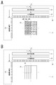
- the area max value detection unit 81 divides an image of one frame into a plurality of areas AR00 to ARnm, and detects the maximum value of the image signal Sig_in input for each area.
- (n + 1) ⁇ (m + 1) areas are formed by dividing the area into n + 1 in the horizontal direction and m + 1 in the vertical direction, but the number of areas in the area division is not limited. What is necessary is just two or more areas.
- the area max value detection unit 81 is not necessarily limited to area division. The maximum value may be detected by setting the number of areas to “1” and using the entire area as one area AR as shown in FIG. 12B.
- the area max value detector 81 supplies the maximum value for each area to the limit processor 80.
- the limit processing unit 80 performs limit processing on the gradation value of each pixel indicated by the rear image signal Sig_RE with the maximum value of the corresponding area as the limit value LL. For example, if the maximum value of the area AR00 is “852” in the image signal Sig_in, the limit processing unit 80 performs limit processing so that the upper limit of the gradation value of the pixel of the area AR00 in the rear image signal Sig_RE is “852”. Do.
- the limit processing unit 80 performs the limit processing so that the upper limit of the gradation value of the pixel of the area AR01 in the rear image signal Sig_RE is “623”. I do.
- the upper limit value of the rear image signal Sig_RE output from the gradation conversion unit 72 by the limit processing unit 80 is limited, thereby obtaining a gamma.
- the level of the rear image signal Sig_RE after conversion does not become larger than the maximum value of the input image signal Sig_in. Since the gamma value of the gamma conversion unit 74 is set to “1” or less, the signal level after the gamma conversion becomes higher than the input level, but the rear image signal is operated by the action of the area max value detection unit 81 and the limit processing unit 80.
- the signal level of Sig_RE becomes low. The light leakage around the white spot that caused image quality degradation was emphasized by the increase in the signal level of the rear image signal Sig_RE. The surrounding light leakage can be reduced and the image quality can be improved.
- the area max value detection unit 81 sets the number of areas to 1 and detects the maximum value of the entire screen, if a signal with a high signal level is received at any one point, the signal level of the limit processing unit 80 Since the limit value is LL, the effect of reducing light leakage is reduced.
- the limit value LL is greater in an area without a high signal than when the number of areas is 1. And the effect of reducing light leakage increases. For this reason, the image quality improvement effect increases as the number of areas increases.
- the circuit scale increases as the number of areas increases, it is desirable to select an appropriate number of areas according to the product to be applied.
- the number of area divisions is the number of pixels (that is, one area per pixel), although it is not realistic. Of course, this is not realistic, and considers one area to have a significant number of pixels (in consideration of image quality improvement effect and circuit scale). Needless to say, the number of pixels determined by Furthermore, the number of pixels and the area shape of each area are not necessarily the same.
- Second Embodiment> A second embodiment will be described.
- the differences from the configuration of FIG. 5 in the first embodiment will be mainly described, and the same parts as those in FIG.
- FIG. 13 shows a rear image generation unit 51 as a second embodiment.
- a lower limit processing unit 82 is provided in addition to the configuration of FIG.
- the output of the lower limit processing unit 82 is supplied to the limit processing unit 80.
- the lower limit processing unit 82 sets the lower limit value of the limit value LL in the limit processing unit 80.
- the lower limit processing unit 82 uses the maximum value detected by the area max value detecting unit 81 as it is. However, if the maximum value is less than the lower limit value, the lower limit value is output to the limit processing unit 82 as the maximum value. In other words, the detected maximum value is replaced with a lower limit value larger than the maximum value and output. Accordingly, the maximum value of each area supplied to the limit processing unit 82 does not become a value less than the lower limit value.
- the limit value LL in the limit processing unit 80 varies depending on the area. For this reason, even if the signal level (gradation value) in the rear image signal Sig_RE input to the limit processing unit 80 is the same, the signal level may differ depending on the area after the limit processing. At this time, the signal level of the front image signal Sig_FR is adjusted by the processing of the light amount correction unit 53 and the division unit 52a so that the displayed image matches the input image even if the signal level on the rear liquid crystal cell 3 side is different.
- the lower limit processing unit 82 sets the lower limit to the limit value LL in the limit processing unit 80, thereby narrowing the limit range of the limit processing unit 80.
- Third Embodiment> The configuration of the third embodiment is shown in FIG. In this example, a time filter unit 84 that suppresses a sudden change in the limit value LL and a scene change detection unit 85 that detects a scene change of an image are provided.
- the time filter unit 84 has an input signal and a signal output in the past, and performs a filtering process so that the output signal does not change abruptly between frames.
- the input in this case is the maximum value of each area detected by the area max value detector 81. That is, the time filter unit 84 performs a filter process so that the maximum value of each area supplied to the limit processing unit 80 does not change rapidly in the time axis direction.
- the time filter unit 84 may be a filter having any characteristic as long as the rapid change of the output signal (maximum value) can be suppressed.
- the maximum value output from the time filter unit 84 is the limit value in the limit processing unit 80.
- the limit value LL in the limit processing unit 80 changes abruptly, and the signal level of the rear image signal Sig_RE changes abruptly.
- the signal level of the front image signal Sig_FR is adjusted so that the displayed image matches the input image signal Sig_in.
- the rear image signal Sig_in is adjusted. There may be a difference between the timing at which the signal level of the liquid crystal cell 3 changes and the timing at which the adjusted signal level of the front liquid crystal cell 2 changes, and the displayed image may change momentarily.
- the time filter unit 84 performs a filtering process so that the signal level does not change suddenly between frames (time axis direction).
- the scene change detection unit 85 is combined.
- the time filter unit 84 has a function of changing the filter characteristics when the scene change detection unit 85 detects a scene change, or a function of switching between valid and invalid filters.
- the scene change detection unit 85 detects a change in the scene as the image content of the current frame of the input image signal Sig_in compared to the previous frame. For example, a scene change is detected when the area where the level has changed in the frame (the number of pixels whose gradation value has changed) is equal to or greater than a set threshold.
- the detection method is not limited to this.
- the scene change detection unit 85 may detect a scene change from the difference between the average value of all pixels of the input image signal Sig_in and the average value of all pixels of the image signal Sig_in calculated one frame before.
- the scene change detection unit 85 may detect a scene change from the maximum value detected by the area max value detection unit 81 instead of the image signal Sig_in. For example, if the number of areas where the maximum value has changed is greater than or equal to a predetermined value, it may be determined that the scene change has occurred.
- the change in the image due to the difference between the timing at which the signal level of the liquid crystal cell 3 changes and the timing at which the signal level of the front liquid crystal cell 2 changes is difficult to be seen at the place where the image is moving (area on the screen). It is easy to see in the place where is stationary. That is, when there is no place on the screen that is stationary and the entire screen changes, the change in the displayed image is difficult to see. For this reason, it is possible to weaken (or turn off) the filtering process of the time filter unit 84. For example, even if the change range of the maximum value allowed between frames is increased or the time filter is turned off, the image quality deterioration is not easily recognized.
- the time filter unit 84 changes the filter processing of the time filter unit 84 in response to the scene change detection.
- the image quality improvement effect is delayed, but the effect delay can be minimized by controlling the time filter by scene change detection.
- a moving image detection unit 83 that detects whether the input image signal Sig_in is a moving image is provided together with the time filter unit 84 and the lower limit processing unit 82.
- the moving image detection unit 83 detects the current frame of the input image signal Sig_in as a moving image if there is a difference in the image signal between frames compared to the previous frame, and if there is no difference in the image signal between frames. Detect as a still image.
- the detection method is not limited to this.
- the moving image detecting unit 83 may detect whether the moving image is a moving image from the maximum value detected by the area max value detecting unit 81 instead of from the image signal Sig_in. For example, if there is an area where the maximum value has changed (or if there is a predetermined number or more), it may be determined to be a moving image.
- the moving image detection unit 83 may detect a still image when the changed value is small or the changed area is small even if there is a difference in the image signal between frames.
- the lower limit processing unit 82 sets the lower limit of the maximum value detected by the area max value detection unit 81 as described above. As a result, the lower limit value of the limit value LL in the limit processing unit 80 is set. In the case of FIG. 15, the lower limit processing unit 82 switches the setting value (a value that is the lower limit of the maximum value to be output) when the moving image detection unit 83 detects a moving image and when it is detected as a still image. To do.
- the maximum value output from the lower limit processing unit 82 is supplied to the limit processing unit 80 after a rapid change is suppressed by performing a filtering process in the time axis direction in the time filter unit 84, and the limit value LL Is done.
- the time filter unit 84 When the time filter unit 84 is provided, when the maximum value input to the time filter unit 84 changes due to its action, a delay of a certain time occurs until the output of the time filter unit 84 approaches the input. This delay becomes longer as the change amount of the input signal (the detected maximum value) becomes larger. However, if the limit range of the limit processing unit 80 is narrowed, the change amount of the signal becomes smaller and the response when the signal changes is quicker. Become. In order to narrow the limit range of the limit processing unit 80, when the lower limit processing unit 82 is provided, the lower limit processing unit 82 may narrow the range through which the maximum value is passed.
- the delay due to the time filter unit 84 does not matter, but the image signal Sig_in is a moving image and the detected maximum value varies. If it is, it is desirable not to make the delay time too long.
- the moving image detection unit 83 detects the moving image, and when the moving image is input, the lower limit processing unit 82 raises the set value as the lower limit value of the maximum value. By raising the lower limit value, the limit range of the limit processing unit 80 can be further narrowed, and the delay time can be shortened.
- the configuration of the fifth embodiment is shown in FIG.
- a spatial filter unit 86 is provided, and the maximum value detected by the area max value detection unit 81 is subjected to spatial filter processing by the spatial filter unit 86 and supplied to the limit processing unit 80.
- the spatial filter unit 86 performs a spatial filter process for smoothing a change between areas divided by the area max value detection unit 81. That is, the spatial filter unit 86 suppresses a signal level difference between areas in order to suppress a rapid change in the signal level between the areas with respect to the maximum value detected by the area max value detection unit 81 divided for each area. Filter. In addition, the filtering process of the spatial filter unit 86 prevents the signal level after the filtering process from becoming smaller than the input signal.
- the spatial filter unit 86 performs a filtering process for suppressing the signal level difference between the areas, thereby improving the double image when observed obliquely.
- the spatial filter unit 86 desirably has a function of returning to the original resolution when the resolution is lower than the resolution of the image signal Sig_in input by the area max value detection unit 81.
- the spatial filter unit 86 restores the original resolution, it is conceivable to perform interpolation processing for the missing signal.
- the area max value detection unit 81 reduces the resolution from the resolution of the image signal Sig_in to the resolution of the number of areas, the spatial filter unit 86 restores the original resolution, but interpolation is performed so that the missing signal is smoothly connected at this time. Processing is performed to prevent the occurrence of a double image due to the difference in signal level between adjacent signals. Note that the above-described interpolation processing is not required when the area max value detection unit 81 has a sufficiently large number of areas.
- the moving image detection unit 83 described in FIG. 15 may be provided, and the detection result of the moving image detection unit 83 may be supplied to the spatial filter unit 86.
- the spatial filter unit 86 changes the filter characteristics between when detecting a moving image and when detecting a still image.
- the spatial filter unit 86 is not necessary when the area max value detection unit 81 sets the number of areas to 1. Furthermore, the spatial filter unit 86 may be omitted when the area max value detection unit 81 has a sufficiently large number of areas.
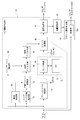
- FIG. This is an example in which the above-described first to fifth embodiments are combined.
- the lower limit value is set by the lower limit processing unit 82 for the maximum value detected by the area max value detection unit 81.
- the setting of the lower limit value is switched according to the detection of a moving image / still image by the moving image detection unit 83.
- the maximum value output from the lower limit processing unit 82 is suppressed from abrupt fluctuations by the time filter unit 84, and further, the change between areas is smoothed by the spatial filter unit 86 and supplied to the limit processing unit 80.
- the dual cell image processing unit 12 (image processing apparatus) converts the gradation value of the image signal Sig_in for the liquid crystal display panel 1 in which the display image is generated by the light passing through the rear liquid crystal cell 3 and the front liquid crystal cell 2. And a limit value for performing a process of limiting the value of the rear image signal Sig_RE output from the tone value conversion unit 72 to the limit value LL by generating the rear image signal Sig_RE for the rear liquid crystal cell 3.
- a processing unit 80 is provided. In other words, limit processing is performed on the rear image signal Sig_RE generated by the tone value conversion.
- the rear image signal Sig_RE is subjected to limit processing based on the limit value LL by the limit processing unit 80 to prevent the rear image tone from becoming too high.
- the signal level of the rear liquid crystal cell 3 is lowered, and light leakage generated around an isolated white spot as a display image is reduced.
- the image quality can be improved.
- an area max value detection unit 81 (maximum value) that detects the maximum value of the input image signal Sig_in.
- the limit processing unit 80 uses the limit value LL as a value based on the maximum value detected by the maximum value detection unit.
- limiter processing is performed with a limit value suitable for the image content. Thereby, an appropriate limit control is realized.
- limit processing unit 80 sets the maximum value detected by area max value detection unit 81 as limit value LL. That is, the maximum value of the input image signal Sig_in is used as it is as the limit value LL. As a result, the maximum value of the rear image signal Sig_RE is limited to the maximum value of the input color image signal Sig_RGB. Accordingly, the gradation value of the rear image can be prevented from becoming too high, and light leakage can be reduced.
- the area max value detector 81 detects the maximum value for each of a plurality of areas set in the image, and the limit processor 80 detects the maximum value in the area for each area.
- the example which performs the limit process by the limit value LL based on this was given. That is, one frame image area is divided into a plurality of areas. Then, the maximum value of the input signal is detected for each area, and the limit processing of the rear image signal Sig_RE is performed with the limit value based on the maximum value for each area. As a result, the rear image signal Sig_RE is subjected to limit processing with a suitable limit value that is different for each area. For example, when the luminance difference is large in the screen, limit processing suitable for the luminance of each area is performed, and the above-described image quality deterioration reduction effect is appropriately exhibited.
- the lower limit value when the maximum value detected by the area max value detection unit 81 is less than the set lower limit value, the lower limit value is set to the maximum value.
- the maximum value that serves as a reference for the limit value in the limit processing unit 80 is always greater than or equal to the lower limit. Therefore, the change in the signal level of the rear image signal Sig_RE can be suppressed, and the change in the displayed image that occurs when the signal level of the front image signal Sig_FR has an error from the optimum value can be minimized. .
- the time filter unit 84 that suppresses the variation in the time axis direction of the maximum value detected by the area max value detection unit 81.
- the maximum value of the current frame of the input image signal Sig_in is the maximum value of the previous frame (in the case of area division, the maximum value of a certain area of the current frame and the maximum value of the corresponding area of all frames), The fluctuation amount is suppressed so that it does not change rapidly. By applying such a time filter, it is possible to reduce the change in the display image that occurs when the signal level of the rear image signal Sig_RE is changed.
- a scene change detection unit 85 for detecting a scene change for the image signal Sig_in is provided, and the time filter unit 84 is used when a scene change is detected.
- An example of changing the filter operation was described.
- the scene change detection unit 85 detects whether or not the scene as the image content has changed by comparing the current frame with the previous frame.
- the time filter unit 84 switches the filter characteristics and switches on / off of the filter processing in response to the scene change being detected.
- the time filter is controlled by scene change detection. As a result, the delay of the effect can be minimized.
- the lower limit process is performed using the maximum value as the lower limit value.
- a moving image detecting unit 83 that detects whether the image signal Sig_in is a moving image
- the lower limit processing unit 82 has different lower limit values depending on whether the image signal Sig_in is a moving image or not.
- An example of value was described.
- the lower limit value in the lower limit process is made different between when the input image signal is a moving image and when it is a still image. That is, in the case of moving images, the lower limit is raised.
- signal delay by the time filter unit 84 may be a problem. Therefore, when performing time filter processing, when the input image signal is detected to be a moving image, the lower limit value is changed to reduce the change in the signal level of the rear image signal Sig_RE. As a result, signal delay due to the time filter can be minimized.
- the spatial filter unit 86 that suppresses the variation amount of the maximum value in the spatial direction for each of the plurality of areas set in the image is provided.
- the filter processing is performed so that the maximum value in each area does not change suddenly in the spatial direction (the direction of the image plane in which a plurality of areas are adjacent).
- the maximum value detection and limiter processing is performed for each area by dividing the area, there is a possibility that a double image is generated due to the level difference between the areas. Therefore, by applying a spatial filter, it is difficult to cause such a problem.
- the gradation value conversion unit 72 performs gamma conversion with a gamma value smaller than 1. This is to perform good gradation expression in a state where the front image and the rear image are combined.
- the gradation value after gamma conversion becomes higher than before gamma conversion. If the signal level (gradation) of the rear image signal Sig_RE becomes too high due to gamma conversion, light leakage around the front image is emphasized, and image quality deterioration is likely to occur. In such a case, it is useful to perform limit processing on the rear image signal Sig_RE.
- the spatial image processing unit 79 that performs spatial filter processing for the rear image signal Sig_RE to expand the transmission pixel range of the image in the rear liquid crystal cell 3 more than the image of the front liquid crystal cell 2 is provided. That is, spatial filter processing is performed so as to blur the rear image. By doing so, for example, it is difficult to generate a double image in the display image, and the viewing angle can be improved. However, in this case, light leakage is likely to occur, so that it becomes more effective to prevent image quality deterioration by limit processing.
- the dual cell image processing unit 12 also includes a front image generation unit 52 that performs arithmetic processing using the rear image signal Sig_RE on the image signal Sig_in to generate a front image signal Sig_FR for the front liquid crystal cell 2.
- the image signal Sig_in input to the dual cell image processing unit 12 is a color image signal
- the gradation value conversion unit 72 performs gradation values on the monochrome image signal (grayscale signal Gr) converted from the color image signal. Perform conversion.
- the front image generation unit 52 generates the front image signal Sig_FR by dividing the rear image signal Sig_RE processed by the limit processing unit 80 from the image signal Sig_in that is a color image signal.
- the dual cell image processing unit 12 includes a light amount correction unit 53 that multiplies the rear image signal Sig_RE by a correction coefficient kLC corresponding to a light amount component incident on the front liquid crystal cell 2, and the front image generation unit 52
- the front image signal Sig_FR is generated by dividing the rear image signal Sig_RE multiplied by the correction coefficient kLC from the signal Sig_in. It is possible to obtain a front image signal Sig_FR in consideration of a light amount component incident on the front liquid crystal cell 2 from the rear liquid crystal cell 3, and to obtain an appropriate gradation as an image obtained by overlapping the rear liquid crystal cell 3 and the front liquid crystal cell 2. can do.
- the display device 90 includes the dual cell type liquid crystal display panel 1 in which a display image is generated by light passing through the rear liquid crystal cell and the front liquid crystal cell, and the dual cell image processing unit 12 described above.
- the liquid crystal display panel 1 a backlight 5, a rear liquid crystal cell 3, a diffusion layer 4, and a front liquid crystal cell 2 are arranged in this order.
- this technique can also take the following structures.
- An image processing apparatus comprising: a limit processing unit that performs processing for limiting a value of a rear image signal output from the gradation value conversion unit to a limit value.
- a maximum value detecting unit for detecting a maximum value of the input image signal The image processing apparatus according to (1), wherein the limit processing unit sets a limit value to a value based on the maximum value detected by the maximum value detection unit.
- the image processing apparatus uses the maximum value detected by the maximum value detection unit as a limit value.
- the maximum value detection unit detects a maximum value for each of a plurality of areas set in the image, The said limit process part performs the limit process by the limit value based on the maximum value in an area for every area.
- the image processing apparatus as described in said (2) or (3).
- a lower limit processing unit that outputs the lower limit value as a maximum value is provided.
- the image processing apparatus according to any one of (2) to (5), further including a time filter unit that suppresses a fluctuation amount of the maximum value detected by the maximum value detection unit in a time axis direction.
- a scene change detection unit that detects a scene change for the input image signal is provided.
- the image processing apparatus according to (6), wherein the time filter unit changes a filter operation when a scene change is detected.
- a front image generation unit that performs arithmetic processing using the rear image signal on the input image signal and generates a front image signal for the front liquid crystal cell;
- the input image signal is a color image signal, and the gradation value conversion unit performs gradation value conversion on the monochrome image signal converted from the color image signal,
- the front image generation unit generates a front image signal by dividing the rear image signal processed by the limit processing unit from an input image signal which is a color image signal.
- a display panel in which a display image is generated by light passing through the rear liquid crystal cell and the front liquid crystal cell;
- a gradation value conversion unit that performs gradation value conversion on an input image signal that is an image signal for the display panel to generate a rear image signal for the rear liquid crystal cell;
- a limit processing unit that performs processing for limiting the value of the rear image signal output from the gradation value conversion unit to a predetermined limit value;
- a display device comprising: a front image generation unit that performs arithmetic processing using the rear image signal on the input image signal to generate a front image signal for the front liquid crystal cell.
- a gradation value for generating a rear image signal for the rear liquid crystal cell by performing gradation value conversion on an input image signal which is an image signal for a display panel in which a display image is generated by light passing through the rear liquid crystal cell and the front liquid crystal cell.
- SYMBOLS 1 Liquid crystal display panel, 2 ... Front liquid crystal cell, 3 ... Rear liquid crystal cell, 4 ... Diffusion layer, 5 ... Back light, 10 ... Image processing apparatus, 11 ... Display image processing part, 12 ... Dual cell image processing part, 20 ... front liquid crystal cell driving unit, 30 ... rear liquid crystal cell driving unit, 51 ... rear image generating unit, 52 ... front image generating unit, 53 ... light quantity correcting unit, 54,57 ... panel gamma processing unit, 55,58 ... adjusting unit 56 ... Rear output unit, 57 ... Front output unit, 70 ... Gray scale conversion unit, 72 ... Tone value conversion unit, 73 ... LUT, 74 ...
Landscapes
- Physics & Mathematics (AREA)
- Engineering & Computer Science (AREA)
- General Physics & Mathematics (AREA)
- Nonlinear Science (AREA)
- Chemical & Material Sciences (AREA)
- Crystallography & Structural Chemistry (AREA)
- Theoretical Computer Science (AREA)
- Computer Hardware Design (AREA)
- Mathematical Physics (AREA)
- Optics & Photonics (AREA)
- Control Of Indicators Other Than Cathode Ray Tubes (AREA)
- Liquid Crystal (AREA)
- Liquid Crystal Display Device Control (AREA)
- Controls And Circuits For Display Device (AREA)
- Ultra Sonic Daignosis Equipment (AREA)
Abstract
Description
このため、例えばリア液晶セルに入力する信号をガンマ値1以下にガンマ変換することで、ある階調以上でリア液晶セルを透過率100%に飽和させたり、リア液晶セルに入力する信号を平面方向に広げるフィルタ処理を行い、視差による画像のズレを低減させることが行われる。
ところが、例えば黒い背景に白点のような小面積の信号を表示したとき、上記のフィルタ処理によりリア液晶セルに表示する白点が広がるが、フロント液晶セルの漏れ光によりリア液晶セルに表示した画像が透けて見え、白点の周りが薄く光って見え、画質が低下してしまうことがある。
また、ガンマ変換処理によりリア液晶セル側の広がった白点がさらに明るくなると、漏れ光が増加してさらに画質が低下する。
そこで本技術はデュアル液晶セル型の表示装置を用いる場合に、これらの画質劣化を軽減することを目的とする。
この画像処理装置が処理対象とする画像信号は、デュアル液晶セル型の液晶表示パネルで用いる画像信号である。画像処理装置は、デュアル液晶セル型の液晶表示パネルのフロント液晶セルとリア液晶セルのそれぞれに対する画像信号の処理を行う。この場合に階調値変換して生成したリア画像信号に対してリミット処理を行うようにする。
即ち入力画像信号の最大値を検出して、リミット値は最大値に基づく値として変化する値とする。
つまり入力信号の最大値をそのままリミット値とする。
つまり1フレームの画像領域を複数のエリアに分割設定する。そしてエリア毎に入力信号の最大値を検出し、エリア毎に、その最大値に基づくリミット値でリア画像信号のリミット処理を行う。
つまり検出された最大値が設定した下限値以上であれば、その検出された最大値をそのまま出力するが、検出された最大値が下限値未満の場合は、その検出された最大値を下限値に置き換えて出力する。
例えば入力画像信号の現在のフレームの最大値が前フレームの最大値(エリア分割する場合は、現在のフレームの或るエリアの最大値と全フレームの該当エリアの最大値)とが、急激に変化しないように変動量を抑制する。
例えばシーンチェンジ検出部は、現在フレームと前フレームの比較により画像内容としてのシーンが変化したか否かを検出する。時間フィルタ部は、シーンチェンジが検出されることに応じてフィルタ特性を切り換えたりフィルタ処理のオン/オフを切り換える。
例えば入力画像信号が動画の場合と静止画の場合とで、下限リミット処理における下限値が異なるようにする。
即ち各エリアにおける最大値について、空間方向(複数のエリアが隣接する画平面方向)に急激な変化が生じないようにフィルタ処理を行う。
フロント画像とリア画像を合わせた状態で良好な階調表現を行うためにガンマ値が1より小さいガンマ変換を行うようにする。この場合にリミット処理を行うようにする。
即ちリア画像をぼかすように空間フィルタ処理を行う。具体的には、フロント画像信号によるフロント液晶セルの画像に対して、リア液晶セル側の透過する画素の範囲が広くされて画像がぼかされるように、リア画像信号に対する低域通過フィルタのような処理を施す。
即ちカラー画像信号である画像信号としての例えばR、G、Bの各階調値について、それぞれリミット処理後のリア画像信号の階調値を除算して、フロント画像信号としてのR、G、Bの階調値を得る。
この表示装置においては、表示パネルは、例えば光源部と、リア液晶セルと、拡散層と、フロント液晶セルが、この順番で配置され、いわゆるデュアル液晶セル型の液晶表示パネルを構成する。このようなデュアル液晶セル型の液晶表示パネルに対するリア画像信号について、リミット処理が行われるようにする。
本技術に係る画像処理方法は、上記の画像処理装置における階調値変換、リミット値に制限する処理が行われるものである。
なお、ここに記載された効果は必ずしも限定されるものではなく、本開示中に記載されたいずれかの効果であってもよい。
<1.表示装置の構成>
<2.第1の実施の形態>
<3.第2の実施の形態>
<4.第3の実施の形態>
<5.第4の実施の形態>
<5.第5の実施の形態>
<3.第6の実施の形態>
<7.まとめ及び変形例>
なお説明上、3原色である赤色(red)、緑色(green)、青色(blue)は、それぞれアルファベットでR,G,Bと表記する。
図1は実施の形態の表示装置90の構成を示している。表示装置90は、液晶表示パネル1、画像処理装置10、フロント液晶セル駆動部20、リア液晶セル駆動部30を有する。
バックライト5の前面側に、リア液晶セル3、拡散層4、フロント液晶セル2がこの順番で重なるように配置されており、視認者はフロント液晶セル2の前面側から表示された画像を見ることになる。
フロント液晶セル2、リア液晶セル3はそれぞれ1つの液晶表示パネルを形成するが、本実施の形態では、デュアル液晶セル型の表示パネル全体を液晶表示パネル1と呼ぶこととする。
画像処理装置10は表示画像処理部11、デュアルセル画像処理部12を有する。
表示画像処理部11は、入力された画像信号S1に対して、必要なデコード処理、輝度処理、色処理、解像度変換等を行い、処理後の画像信号Sig_inをデュアルセル画像処理部12に供給する。少なくとも画像信号Sig_inの段階では、R、G、Bの各色の階調値を示すカラー画像信号とされている。
即ちデュアルセル画像処理部12は入力された画像信号Sig_inに対する信号処理を行い、フロント液晶セル2に対する画像信号(フロント画像信号Sig_FR)、及びリア液晶セル3に対する画像信号(リア画像信号Sig_RE)を生成して出力する。
フロント画像信号Sig_FRはR、G、Bの階調値を含むカラー画像信号である。一方、リア画像信号Sig_REはグレースケールとしての階調値を含む白黒(グレースケール)画像信号である。
画像処理装置10から出力されるリア画像信号Sig_REはリア液晶セル駆動部30に供給される。リア液晶セル駆動部30はリア画像信号Sig_REに基づいてリア液晶セル3を駆動し、白黒画像表示を実行させる。
フロント液晶セル駆動部20は、表示制御部21と、垂直駆動部22と、水平駆動部23を有し、これらの構成でフロント液晶セル2を駆動する。
垂直駆動部22は、表示制御部21から供給される制御信号に基づいて、フロント液晶セル2における表示駆動の対象となる1水平ラインを順次選択する。
水平駆動部23は、表示制御部21から供給される画像信号および制御信号に基づいて、1水平ライン分の画素電圧を生成し、垂直駆動部22が選択した1水平ライン分のサブ画素26(26R,26G,26B)に供給する。
各画素25は、3つのサブ画素26R,26G,26Bを有している。
サブ画素26Rは、赤色のカラーフィルタを有するものであり、サブ画素26Gは、緑色のカラーフィルタを有するものであり、サブ画素26Bは青色のカラーフィルタを有するものである。
これらのサブ画素26R,26G,26Bには、水平駆動部23から画素電圧がそれぞれ供給される。そして、サブ画素26R,26G,26Bは、画素電圧に応じて、光の透過率をそれぞれ変化させるようになっている。
リア液晶セル駆動部30は、表示制御部31と、垂直駆動部32と、水平駆動部33を有し、これらの構成でリア液晶セル3を駆動する。
垂直駆動部32は、表示制御部31から供給される制御信号に基づいて、フロント液晶セル2における表示駆動の対象となる1水平ラインを順次選択する。
水平駆動部33は、表示制御部31から供給される画像信号および制御信号に基づいて、1水平ライン分の画素電圧を生成し、垂直駆動部32が選択した1水平ライン分のサブ画素36に供給するものである。
各画素35は、3つのサブ画素36を有している。各サブ画素36は、カラーフィルタを有しないものである。すなわち、フロント液晶セル2における各サブ画素26R,26G,26Bは、対応する色のカラーフィルタを有するようにしたが、リア液晶セル3における各サブ画素36は、カラーフィルタを有しない。
1つの画素35に属する3つのサブ画素36には、水平駆動部33から同じ画素電圧が供給される。そして、サブ画素36は、画素電圧に応じて、光の透過率を変化させるようになっている。
なお、リア液晶セル3の画素35は、上記の3つのサブ画素分を1つの電極、及びブラックマトリックスの1画素として構成してもよい。即ち、カラーフィルタレスだけでなく、TFT、透明電極、配線、ブラックマトリックスという各液晶構造要素についてもサブ画素を持たない構造とされることもある。その場合、1つの画素35は、フロント液晶セル2における3つのサブ画素26R,26G,26Bに対応することになる。
バックライト5は、例えばLED(Light Emitting Diode)による発光部を備えて発光を行う。
図示するように液晶表示パネル1では、バックライト5、リア液晶セル3、拡散層4、フロント液晶セル2が、この順に配置されており、図3におけるフロント液晶セル2の上面が、表示面DPになっている。
つまり、バックライト5から射出した光が、バックライト5、リア液晶セル3、拡散層4、フロント液晶セル2を順に通過し、視認者に届くようになっている。
フロント液晶セル2およびリア液晶セル3は、互いに離間して配置されている。そして、このフロント液晶セル2とリア液晶セル3の間の空隙8には、拡散層4が配置されている。
なお構成例としては、フロント液晶セル2とリア液晶セル3のセル間を隙間なく接着層で密着させる場合もある。
基板122,124は、例えばガラス基板により構成されるものであり、互いに対向するように配置されている。
基板122の基板124側の面には、サブ画素26ごとに画素電極が形成され、上述の水平駆動部23により画素電圧が印加されるようになっている。
基板124の基板122側の面には、各サブ画素26に共通の電極が形成されている。また、基板124には、カラーフィルタや、ブラックマトリクスが形成されている。
液晶層123は、基板122と基板124との間に封止されたものであり、基板122の画素電極に印加された画素電圧に応じて、光の透過率が変化するものである。
偏光板121は、基板122の光入射側に貼り付けられており、偏光板125は、基板124の光出射側に貼り付けられている。偏光板121の透過軸と偏光板125の透過軸とは、互いに交差するようになっている。
基板132,134は、例えばガラス基板により構成されるものであり、互いに対向するように配置されている。
基板132の基板134側の面には、サブ画素26ごとに画素電極が形成され、上述の水平駆動部33により画素電圧が印加されるようになっている。
なお上述のようにサブ画素を持たない構造も考えられ、その場合、画素35ごとに画素電極が形成される。
基板134の基板132側の面には、各サブ画素36に共通の電極が形成されている。また、基板134には、ブラックマトリクスが形成されている。そして基板134には、フロント液晶セル2の基板124とは異なり、カラーフィルタは形成されていない。
液晶層133は、基板132と基板134との間に封止されたものであり、基板132の画素電極に印加された画素電圧に応じて、光の透過率が変化するものである。
偏光板131は、基板132の光入射側に貼り付けられており、偏光板135は、基板134の光出射側に貼り付けられている。偏光板131の透過軸と偏光板135の透過軸とは、互いに交差するようになっている。
この拡散層4は、表示画像におけるモアレを低減するためのものである。すなわち、液晶表示パネル1は、2枚の液晶表示パネルであるフロント液晶セル2とリア液晶セル3を重ねて配置しているため、表示画像にモアレが生じてしまうおそれがある。そこで液晶表示パネル1では、拡散層4をフロント液晶セル2とリア液晶セル3の間に配置することにより、モアレを低減し、画質の低下を抑えるようにしている。
この場合、拡散層4とフロント液晶セル2との間、および拡散層4とリア液晶セル3との間のうちの一方または双方に透明材料層を形成してもよい。
また、拡散層4をフロント液晶セル2に隣接するように(dFR1=0)配置するのがより望ましい。拡散層4をフロント液晶セル2に近づけるほど、モアレをより効果的に抑制することができ、また鮮鋭度を高めることができるためである。
また、拡散層4のヘイズ値が低い場合でも、例えば、拡散層4をフロント液晶セル2に近付けて配置することにより所望の画質を得ることができる。
発光アレイ42は例えばLEDが配列されて構成されている。
第1の実施の形態としてのデュアルセル画像処理部12の構成を図4,図5で説明する。
図4はデュアルセル画像処理部12のブロック図であり、図5は図4におけるリア画像生成部51内を詳細に示したブロック図である。
画像信号Sig_inは例えばR、G、Bについてそれぞれ10ビットによる1024階調の信号である。もちろん1024階調(10ビット)とするのは説明上の一例に過ぎず、より少ない又はより多い階調(ビット数)の信号としてもよい。
リア画像信号Sig_REはパネルガンマ処理部54でリア液晶セル3に応じたガンマ処理が施された後、調整部55で必要な調整処理が施される。そしてリア出力部56で遅延調整処理や3つのサブ画素36に対応する並列化等が行われ、リア液晶セル駆動部30に供給される。
なお、上述のようにリア液晶セル3にサブ画素が構成されない場合、リア画像信号Sig_REは、フロント液晶セル2における3つのサブ画素26R,26G,26Bに対応する3つのタイミングのフロント画像信号Sig_FRに対応して出力される。
光量補正係数kLCは例えば固定値である。但し光量補正係数kLCは可変値とすることも考えられる。例えば画像に応じて適応的に光量補正係数kLCが算出されるものとしてもよい。
但し、実際にはリア液晶セル3からの出射からフロント液晶セル2に入射されるまでには光量差が生ずるため、正確には単純な除算ではなく補正が必要である。そこで光量補正部53でリア画像信号Sig_REを補正している(Sig_RE・kLC)。
このため、フロント画像生成部52(除算部52a)では、フロント画像信号Sig_FRを、
Sig_FR=Sig_in/(Sig_RE・kLC)
として算出することとしている。
Sig_FR(R)=Sig_in(R)/(Sig_RE・kLC)
Sig_FR(G)=Sig_in(G)/(Sig_RE・kLC)
Sig_FR(B)=Sig_in(B)/(Sig_RE・kLC)
としてフロント画像信号Sig_FRを生成することになる。
R、G、Bの階調値Sig_FR(R)、Sig_FR(G)、Sig_FR(B)は、それぞれ例えば10ビットで1024階調(0~1023)の信号である。
リア画像生成部51では、入力されたカラー画像信号である画像信号Sig_inを、グレースケール変換部70でグレースケール信号(白黒画像信号)Grに変換する。
グレースケール変換は、係数kR,kG,kBを用いて、
Gr=kR・Sig_in(R)+kG・Sig_in(G)+kB・Sig_in(B)
として行う。
即ち、画像信号Sig_inに含まれるR、G、Bのそれぞれの階調値Sig_in(R)、Sig_in(G)、Sig_in(B)に対応してR用の係数kR、G用の係数kG、B用の係数kBを乗算し、それらを加算することでグレースケール信号Grとする。このグレースケール信号Grは、W(白色)としての階調値(0~1023)となる。
階調変換部72は、LUT(Look Up Table)73とガンマ変換部74で構成される。ガンマ変換部74は、入力されたグレースケール信号Grの階調値をLUT入力信号LUT inとしてLUT73を参照し、対応する出力階調値(LUT出力信号LUTout)を得る。そしてその出力階調値LUToutをリア画像信号Sig_REとして出力する。この場合、リア画像信号Sig_REはリミット処理部80に供給される。
この場合ガンマ値は“1”より小さい値に設定されており、ガンマ変換後の値はガンマ変換前の値より高くなる。
また図6Bは、フロント液晶セル2,リア液晶セル3における光の透過率を表すものである。この図6Bにおいて、横軸は、フロント液晶セル2,リア液晶セル3へ供給される信号の階調レベルを示し、縦軸は、透過率L2,L3を示す。ここで、透過率L2は、フロント液晶セル2における透過率を示し、透過率L3は、リア液晶セル3における透過率を示す。
そこで、液晶表示パネル1では、階調レベルが高い範囲において、リア液晶セル3における透過率L3を一定(100%)にし、階調レベルが上記の例えば約40[%]より低い範囲において、リア液晶セル3における透過率L3を階調レベルに応じて変化させていくようにする。
これにより、液晶表示パネル1では、フロント液晶セル2における透過率L2とリア液晶セル3における透過率L3との積Ltotalが、階調レベルが低い範囲においても、階調レベルが高い範囲と同様に、階調レベルに応じて変化するようにすることができる。従って液晶表示パネル1では、例えば、1枚の液晶セルを用いて構成した場合に比べ、低階調範囲において透過率Ltotalを低くすることができるため、コントラストを高めることができる。
階調変換部72は、この図6Bに示した透過率L3を実現できるように、ガンマ変換を行う。この場合の変換特性が例えば図6Aのようになる。即ち入力階調値が或る階調値より高い範囲において、出力階調値が最高階調値となるようにしている。
階調変換部72から出力階調値LUToutとして出力される信号が、リア画像信号Sig_REとなる。
リミット処理部80におけるリミット値は、エリアマックス値検出部81からの出力値で決定される。
エリアマックス値検出部81は、入力される画像信号Sig_inにおけるR、G、Bのそれぞれの階調値Sig_in(R)、Sig_in(G)、Sig_in(B)のうちで最大値を検出し、検出した最大値をリミット処理部80に出力する。この図5の例では、この最大値がリミット処理部80におけるリミット値とされる。
リミット処理部80及びエリアマックス値検出部81については、詳しくは後述する。
例えば空間処理部79はFIR(Finite Impulse Response)フィルタによりフィルタ処理を行うものである。このFIRフィルタは、低域通過フィルタとして機能するものであり、リア液晶セル3に表示する画像をぼかすものである。これにより、表示装置90では、観察者が表示画像を観察したときに、その表示画像に画欠けや2重画が生じるおそれを低減することができるようになっている。FIRフィルタのタップ数は、表示画像に画欠けや2重画が生じないような視野角の目標値θに応じて設定されるものである。
この例では、フロント液晶セル2は表示要素a11を表示し、リア液晶セル3はフロント液晶セル2における表示要素a11の表示位置に対応する位置に、表示要素a12を表示する。表示要素a12は、空間フィルタ処理によりぼかされているため、表示要素a12の幅w12は、表示要素a12の幅w11よりも大きい。
表示要素a11の階調は破線で示すように、透過範囲内で当該表示要素a11の本来の階調値で一定となる。一方、表示要素a11の階調は実線で示すように山なりな分布となる。空間フィルタ処理では、リア液晶セル3における透過画素範囲をフロント液晶セル2よりも広げ、しかも上記のような山なりな階調変化が生じて画像がぼけるような処理をリア画像信号Sig_REに施すことになる。
図8A、図8Bは、図7と同様にフロント液晶セル2,リア液晶セル3の断面模式図と、各液晶セル2,3における階調(輝度)を示している。図8Aはリア画像信号Sig_REに空間フィルタ処理を施した場合、図8Bは空間フィルタ処理を施していない場合である。
表示面の法線方向から角度φの方向にいるユーザが、このような表示画像を観察した場合、範囲C11において、表示要素a11を観察する。
このとき範囲C11において、フロント液晶セル2における光の透過率は高いが、リア液晶セル3における光の透過率は低い部分が生ずる。このため表示要素a11の一部が欠けて視認されしまうことが生じる場合がある。
また範囲C13においては、フロント液晶セル2における光の透過率は低いが、リア液晶セル3における光の透過率は高い。すると、この範囲C13におけるフロント液晶セル2の透過率が十分に低くない場合に、表示画像に2重画が生じてしまうおそれがある。
表示面の法線方向から角度φの方向にいるユーザが、範囲C11において、表示要素a11を観察すると、表示要素a11における光の透過率は高く、また表示要素a12における光の透過率はなだらかに変化するため、画欠けが生じにくいこととなる。
また範囲C12では、フロント液晶セル2における光の透過率は低く、かつリア液晶セル3における光の透過率はなだらかに変化する。よって、表示装置1では、表示画像に2重画が生じるおそれを低減することができる。これらの結果、表示装置90では画質を高めることができる。
そして特に、リミット処理部80とエリアマックス値検出部81によりリア画像信号Sig_REの上限値を適応的に制限することで、画質改善を行う。具体的には表示装置90においてリア液晶セル3の信号レベルが下がることにより孤立した白点の周りに発生する光漏れが低減されるようにする。また光漏れ低減により斜めから見た二重像が改善されるようにもする。
図9Aは入力される画像信号Sig_inの波形の一部を示しているとする。これは、入力画像信号Sig_inが図9Dのように小さいドットの白画像を表示するための白点部分の階調値に対応する信号であるとする。破線のレベルが最高階調を示すものとしている。画像信号Sig_inから変換されるグレースケール信号Grも、これに近い階調の波形となる。
上述の図5の処理からわかるように、グレースケール信号Grは階調変換部72で変換されることで、例えば図9Bのような波形になる。即ち図6Aのガンマ特性により最高階調値に変換されたとする。これがリア画像信号Sig_REとなる。
リア画像信号Sig_REはさらに空間処理部79で処理され、図9Cのような空間方向に広がりを持った波形とされる(階調レベルが山なりに分布する状態となる)。
すると、リア画像信号Sig_REによるリア液晶セル3の画像は図9Eのように白点が広くボケた画像となる。フロント液晶セル2の画像は、図9Fのように本来の白点の画像となる。
従って光漏れを軽減するには、リア液晶セル3の輝度が高くなることをある程度抑制すれば良いことになる。
図10Aは図9Aと同じく入力される画像信号Sig_inの波形を示し、図10B及び図10Cは、生成されるリア画像信号Sig_REとフロント画像信号Sig_FRの波形を示している。
図10Bは特にリア画像信号Sig_REにリミット処理を行わない場合で、リア液晶セル3の輝度が高くなっている状態、図10Cはリア画像信号Sig_REにリミット処理を施し、リア液晶セル3の輝度を抑制した状態である。
図10Bの場合は光漏れによるフレアが目立ち、またそれによりコントラストも悪化している。一方で図10Cの場合は、リア液晶セル3の輝度を抑えることで光漏れによるフレアが減少し、これによりコントラストも改善している。
そこで本実施の形態では、この図10Cのように画質改善を行うためにリミット処理部80及びエリアマックス値検出部81を設けている。
そしてリミット処理部80は、エリアマックス値検出部81で検出される最大値をリミット値LLとして用いる。
また、エリアマックス値検出部81は必ずしもエリア分割することに限られない。エリア数を“1”として図12Bのように全体を1つのエリアARとして最大値検出を行ってもよい。
リミット処理部80は、リア画像信号Sig_REで示される各画素の階調値について、該当するエリアの最大値をリミット値LLとしてリミット処理を行う。
例えば画像信号Sig_inにおいてエリアAR00の最大値が“852”であれば、リミット処理部80は、リア画像信号Sig_REにおけるエリアAR00の画素の階調値の上限が“852”となるようにリミット処理を行う。
また例えば画像信号Sig_inにおいてエリアAR01の最大値が“623”であれば、リミット処理部80は、リア画像信号Sig_REにおけるエリアAR01の画素の階調値の上限が“623”となるようにリミット処理を行う。
ガンマ変換部74のガンマ値が“1”以下に設定されているため、ガンマ変換後の信号レベルは入力レベルより高くなるが、エリアマックス値検出部81とリミット処理部80の作用によりリア画像信号Sig_REの信号レベルが低くなる。
画質劣化をもたらしていた白点の周りの光漏れは、リア画像信号Sig_REの信号レベルが高くなることで強調されていたため、上記作用によりリア画像信号Sig_REの信号レベルが低くなることで白点の周りの光漏れを低減させ、画質を高めることができる。
エリアマックス値検出部81における検出単位としてのエリア数を増やすことで、画面内で輝度差の大きい映像が入った場合でも、高い信号の無いエリアにおいては、エリア数1とした場合よりリミット値LLが低くなり、光漏れの低減効果が高まる。このためエリア数を増やすほど画質改善効果が高まる。一方で、エリア数を増やすほど回路規模が増大するため、適用する製品に応じて適切なエリア数を選択することが望ましい。
なお、エリアの分割数は、極論すれば画素数(つまり1画素で1エリア)となるが、もちろんそれは現実的ではなく、1つのエリアを有意な画素数(画質改善効果と回路規模を勘案して決められる画素数)とすることはいうまでもない。
さらに各エリアの画素数やエリア形状は、必ずしも同じでなくてもよい。
第2の実施の形態を説明する。なお、以下の実施の形態で用いる図面では、第1の実施の形態における図5との構成の違いを中心に述べていき、図5と同一部分は同一符号を付して重複説明を避ける。
この場合、図5の構成に加えて下限リミット処理部82が設けられる。
リミット処理部80には下限リミット処理部82の出力が供給される。この下限リミット処理部82によりリミット処理部80におけるリミット値LLの下限値が設定されるようにしている。
これによってリミット処理部82に供給される各エリアの最大値は、下限値未満の値にはならない。
このときリア液晶セル3側の信号レベルが異なっても表示される画像が入力された画像と一致するようにフロント画像信号Sig_FRの信号レベルは、光量補正部53及び除算部52aの処理で調整される。
しかし、補正精度不足や温度、視野角特性などの要因によりフロント画像信号Sig_FRの信号レベルが最適なレベルからずれた場合、入力される画像信号Sig_inの段階で同じ信号レベルであってもエリアによって輝度の差異が生じる場合もある。
この差異はリア画像信号Sig_REのエリア毎の信号レベルの差が大きいほど差が大きくなる。そこで下限リミット処理部82によりリミット処理部80におけるリミット値LLに下限を設定することで、リミット処理部80の制限範囲を狭くする。制限範囲が狭くなることでリア画像信号Sig_REのエリア毎の信号レベル差も小さくなり、画面上の場所による画像の差異も小さくなることになる。
第3の実施の形態の構成を図14に示す。この例ではリミット値LLが急激に変化することを抑制する時間フィルタ部84、及び画像のシーンチェンジを検出するシーンチェンジ検出部85が設けられる。
時間フィルタ部84は出力信号(最大値)の急激な変化が抑制できればどのような特性のフィルタでもよい。
時間フィルタ部84から出力される最大値がリミット処理部80におけるリミット値となる。
除算部52aにおいては、表示される画像が入力した画像信号Sig_inと一致するようにフロント画像信号Sig_FRの信号レベルを調整しているが、フロント液晶セル2とリア液晶セル3の応答時間差により、リア液晶セル3の信号レベルが変化するタイミングと調整したフロント液晶セル2の信号レベルが変化するタイミングにずれが生じ、一瞬、表示される画像が変化してしまう場合がある。
このような画像の変化を視認できないレベルまで抑えるため、時間フィルタ部84により信号レベルがフレーム間(時間軸方向)で急激に変化しないようなフィルタ処理を施すものである。
そして時間フィルタ部84は、シーンチェンジ検出部85でシーンチェンジが検出された場合に、フィルタ特性を変化させる機能、またはフィルタの有効無効を切り替える機能を有するものとする。
もちろん、検出手法はこれに限られない。例えばシーンチェンジ検出部85は、入力した画像信号Sig_inの全画素の平均値と1フレーム前で算出した画像信号Sig_inの全画素の平均値との差分からシーンチェンジを検出してもよい。
さらにはシーンチェンジ検出部85は、画像信号Sig_inではなくエリアマックス値検出部81で検出した最大値からシーンチェンジを検出してもよい。例えば最大値が変化したエリアの数が所定以上であればシーンチェンジと判定することが考えられる。
つまり、画面上で静止している場所が無く、画面全体が変化した場合は、表示される画像の変化が視認されにくい。このため、時間フィルタ部84のフィルタ処理を弱める(もしくはオフにする)ことが可能である。例えばフレーム間で許容する最大値の変化幅を大きくしたり、時間フィルタをオフにしても、画質劣化は視認されにくい。
そこで時間フィルタ部84は、シーンチェンジ検出に応じて時間フィルタ部84のフィルタ処理を変化させるようにする。
時間フィルタを常時機能させると、画質改善効果が遅延して生じるが、シーンチェンジ検出で時間フィルタを制御することにより、効果の遅延を最小限に抑えることができる。
第4の実施の形態の構成を図15に示す。この例では、時間フィルタ部84、下限リミット処理部82とともに、入力される画像信号Sig_inが動画であるか否かを検出する動画検出部83が設けられる。
なお検出手法はこれに限られない。例えば動画検出部83は、画像信号Sig_inからではなく、エリアマックス値検出部81で検出した最大値から動画であるか否かを検出してもよい。例えば最大値が変化したエリアが存在すれば(又は所定数以上存在すれば)動画と判定することが考えられる。
また動画検出部83は、フレーム間で画像信号に差異があっても変化した値が小さい場合や、変化した面積が小さい場合は静止画として検出してもよい。
この遅れは入力信号(検出された最大値)の変化量が大きくなるほど長くなるが、リミット処理部80の制限範囲を狭くすれば信号の変化量が小さくなり、信号が変化した時の応答が早くなる。リミット処理部80の制限範囲を狭くするには、下限リミット処理部82が設けられる場合、下限リミット処理部82で最大値がそのまま通過される範囲を狭くすればよいことになる。
また、画像信号Sig_inが静止しており、検出される最大値の変化が生じない場合は、時間フィルタ部84による遅れは問題にならないが、画像信号Sig_inが動画で、検出される最大値が変動している場合には遅れ時間が長くなりすぎない方が望ましい。
第5の実施の形態の構成を図16に示す。この例では、空間フィルタ部86を設け、エリアマックス値検出部81で検出された最大値は空間フィルタ部86で空間フィルタ処理が施されてリミット処理部80に供給されるようにしている。
また空間フィルタ部86のフィルタ処理はフィルタ処理後の信号レベルが入力した信号より小さくならないようにする。
そこで、エリア間の信号レベル差を緩和させるため、空間フィルタ部86によりエリア間の信号レベル差を抑制するフィルタ処理を施し、斜めから観察した時の二重像を改善させるようにする。
エリアマックス値検出部81にて解像度を画像信号Sig_inの解像度からエリア数の解像度に落とした場合は、空間フィルタ部86で元の解像度に戻すが、このとき不足した信号が滑らかにつながるように補間処理を施し、隣接した信号レベル差による二重像の発生を予防する。
なお、前述した補間処理はエリアマックス値検出部81のエリア数が十分多い場合は不要となる。
さらに空間フィルタ部86はエリアマックス値検出部81のエリア数が十分多い場合は省略してもよい。
第6の実施の形態を図17に示す。これは上述の第1~第5の実施の形態を組み合わせた例である。
エリアマックス値検出部81で検出される最大値は下限リミット処理部82で下限値が設定される。下限値の設定は動画検出部83による動画/静止画の検出に応じて切り換えられる。
下限リミット処理部82から出力される最大値は時間フィルタ部84で急激な変動が抑えられたうえ、更に空間フィルタ部86でエリア間の変化がなめらかにされて、リミット処理部80に供給される。
この構成例により、上述してきた各実施の形態の効果が総合的に得られる。
以上の実施の形態では次のような効果が得られる。
実施の形態のデュアルセル画像処理部12(画像処理装置)は、リア液晶セル3とフロント液晶セル2を通過した光により表示画像が生成される液晶表示パネル1に対する画像信号Sig_inについて階調値変換を行ってリア液晶セル3に対するリア画像信号Sig_REを生成する階調値変換部72と、階調値変換部72から出力されるリア画像信号Sig_REの値をリミット値LLに制限する処理を行うリミット処理部80を備える。
つまり階調値変換して生成したリア画像信号Sig_REに対してリミット処理を行うようにしている。
リア画像信号Sig_REの信号レベル(階調)が高くなりすぎると、フロント画像の周囲の光漏れが強調され画質劣化が生じることがある。そこでリア画像信号Sig_REは、リミット処理部80によってリミット値LLによるリミット処理を行うようにし、リア画像の階調が高くなりすぎることを防止する。これにより、リア液晶セル3の信号レベルが下がり、表示画像としての孤立した白点の周りに発生する光漏れが低減するため、結果として画質を向上させることができる。
また光漏れは画面を斜めから見ると二重像のように見えるため、光漏れ低減により斜めから見た二重像が改善することにもなる。
入力画像信号、即ち入力されるカラー画像信号Sig_RGBの最大値に基づいてリミット値を設定することで、画像内容に適したリミット値によるリミッタ処理が行われる。これにより適度なリミット制御が実現される。
つまり入力される画像信号Sig_inの最大値をそのままリミット値LLとする。
これによりリア画像信号Sig_REの最大値は、入力されるカラー画像信号Sig_RGBの最大値に制限される。従ってリア画像の階調値が高くなりすぎることを防止し、光漏れを低減することができる。
つまり1フレームの画像領域を複数のエリアに分割設定する。そしてエリア毎に入力信号の最大値を検出し、エリア毎に、その最大値に基づくリミット値でリア画像信号Sig_REのリミット処理を行う。
これによりリア画像信号Sig_REは、エリア毎に異なる適したリミット値でリミット処理される。例えば画面内で輝度差が大きい場合、それぞれのエリアの輝度に適したリミット処理が行われ、上述の画質劣化軽減効果が適切に発揮される。
この下限リミット処理部82による下限値リミット処理により、リミット処理部80でのリミット値の基準になる最大値は、必ず下限値以上となる。
そのためリア画像信号Sig_REの信号レベルの変化を抑えることができ、フロント画像信号Sig_FRの信号レベルが最適値から誤差が生じた場合に発生する、表示される画像の変化を最小限に抑えることができる。
例えば入力される画像信号Sig_inの現在のフレームの最大値が前フレームの最大値(エリア分割する場合は、現在のフレームの或るエリアの最大値と全フレームの該当エリアの最大値)とが、急激に変化しないように変動量を抑制する。
このような時間フィルタを施すことにより、リア画像信号Sig_REの信号レベルを変化させた時に発生する表示画像の変化を低減することができる。
例えばシーンチェンジ検出部85は、現在フレームと前フレームの比較により画像内容としてのシーンが変化したか否かを検出する。時間フィルタ部84は、シーンチェンジが検出されることに応じてフィルタ特性を切り換えたり、フィルタ処理のオン/オフを切り換える。
時間フィルタ処理を行うことで画質改善効果が遅延して生じることになるが、このためシーンチェンジがあると、効果が良好に発揮されない場合がある。そこでシーンチェンジ検出で時間フィルタを制御する。これにより効果の遅延を最小限に抑えることができる。
例えば入力画像信号が動画の場合と静止画の場合とで、下限リミット処理における下限値が異なるようにする。即ち動画の場合は下限値を引き上げる。
動画入力時は時間フィルタ部84による信号の遅延が問題となることが有り得る。そこで時間フィルタ処理を行う場合において、入力画像信号が動画であると検出されたときには下限値を変化させ、リア画像信号Sig_REの信号レベルの変化を小さくする。これにより時間フィルタによる信号の遅れを最小限に抑えることができる。
即ち各エリアにおける最大値について、空間方向(複数のエリアが隣接する画平面方向)に急激な変化が生じないようにフィルタ処理を行う。
エリア分割して最大値検出及びリミッタ処理をエリア単位で行う場合、エリア間レベル差による二重像が発生する不具合が生じる可能性がある。そこで空間フィルタを施すことによりこのような不具合が生じにくいようにする。
ここでガンマ値が1より小さいガンマ変換を行うことで、ガンマ変換後の階調値はガンマ変換前より高くなる。ガンマ変換によりリア画像信号Sig_REの信号レベル(階調)が高くなりすぎると、フロント画像の周囲の光漏れが強調され画質劣化が生じやすい。
そこでこのような場合に、リア画像信号Sig_REについてリミット処理を行うことが有用となる。
即ちリア画像をぼかすように空間フィルタ処理を行う。
このようにすることで、例えば表示画像に2重画が生じにくくなったり視野角を改善できる。但しこの場合に光漏れが生じやすくなるため、リミット処理による画質劣化防止がより有効となる。
即ちカラー画像信号である画像信号としての例えばR、G、Bの各階調値について、それぞれリミット処理後のリア画像信号の階調値を除算して、フロント画像信号としてのR、G、Bの階調値を得る。
これによりリア液晶セル3とフロント液晶セル2を重ねた画像として適切な階調が得られる状態とすることができる。
リア液晶セル3からフロント液晶セル2に入射する光量成分を考慮したフロント画像信号Sig_FRを得ることができ、リア液晶セル3とフロント液晶セル2を重ねた画像として適切な階調が得られる状態とすることができる。
液晶表示パネル1は、バックライト5と、リア液晶セル3と、拡散層4と、フロント液晶セル2が、この順番で配置されている。
本実施の形態では、このようなデュアル液晶セル型の液晶表示パネル1に対して、リア画像信号Sig_REのレベルが高くなることにより生ずる画質劣化を軽減することができる。
(1)
リア液晶セルとフロント液晶セルを通過した光により表示画像が生成される表示パネルに対する画像信号である入力画像信号について階調値変換を行って前記リア液晶セルに対するリア画像信号を生成する階調値変換部と、
前記階調値変換部から出力されるリア画像信号の値をリミット値に制限する処理を行うリミット処理部と、を備えた
画像処理装置。
(2)
前記入力画像信号の最大値を検出する最大値検出部を備え、
前記リミット処理部は、リミット値を前記最大値検出部で検出された最大値に基づいた値とする
上記(1)に記載の画像処理装置。
(3)
前記リミット処理部は、前記最大値検出部で検出された最大値をリミット値とする
上記(2)に記載の画像処理装置。
(4)
前記最大値検出部は、画像内に設定した複数のエリア毎に最大値を検出し、
前記リミット処理部は、エリア毎に、エリア内の最大値に基づいたリミット値によるリミット処理を行う
上記(2)又は(3)に記載の画像処理装置。
(5)
前記最大値検出部で検出された最大値が設定した下限値未満の場合、前記下限値を最大値として出力する下限リミット処理部を備えた
上記(2)乃至(4)のいずれかに記載の画像処理装置。
(6)
前記最大値検出部で検出される最大値の時間軸方向の変動量を抑制する時間フィルタ部を備えた
上記(2)乃至(5)のいずれかに記載の画像処理装置。
(7)
入力画像信号についてのシーンチェンジを検出するシーンチェンジ検出部を備え、
前記時間フィルタ部は、シーンチェンジが検出された場合はフィルタ動作を変化させる
上記(6)に記載の画像処理装置。
(8)
前記最大値検出部で検出された最大値が設定した下限値未満の場合、最大値を前記下限値とする下限リミット処理部と、
入力画像信号が動画であるか否かを検出する動画検出部を備え、
前記下限リミット処理部は、入力画像信号が動画である場合と動画でない場合とで、前記下限値を異なる値とする
上記(6)又は(7)に記載の画像処理装置。
(9)
画像内に設定した複数のエリア毎における最大値の空間方向の変動量を抑制する空間フィルタ部を備えた
上記(4)に記載の画像処理装置。
(10)
前記階調値変換部は、ガンマ値が1より小さいガンマ変換を行う
上記(1)乃至(9)のいずれかに記載の画像処理装置。
(11)
前記リア画像信号に対して、前記リア液晶セルにおける画像の透過画素範囲を前記フロント液晶セルの画像よりも広げる空間フィルタ処理を行う空間処理部を、備えた
上記(1)乃至(10)のいずれかに記載の画像処理装置。
(12)
前記入力画像信号に対して前記リア画像信号を用いた演算処理を行って、前記フロント液晶セルに対するフロント画像信号を生成するフロント画像生成部を備え、
前記入力画像信号はカラー画像信号であり、前記階調値変換部は、前記カラー画像信号から変換した白黒画像信号に対して階調値変換を行い、
前記フロント画像生成部は、カラー画像信号である入力画像信号から前記リミット処理部で処理された前記リア画像信号を除算することでフロント画像信号を生成する
上記(1)乃至(11)のいずれかに記載の画像処理装置。
(13)
リア液晶セルとフロント液晶セルを通過した光により表示画像が生成される表示パネルと、
前記表示パネルに対する画像信号である入力画像信号について階調値変換を行って前記リア液晶セルに対するリア画像信号を生成する階調値変換部と、
前記階調値変換部から出力されるリア画像信号の値を所定のリミット値に制限する処理を行うリミット処理部と、
前記入力画像信号に対して前記リア画像信号を用いた演算処理を行って、前記フロント液晶セルに対するフロント画像信号を生成するフロント画像生成部と、を備えた
表示装置。
(14)
リア液晶セルとフロント液晶セルを通過した光により表示画像が生成される表示パネルに対する画像信号である入力画像信号について階調値変換を行って前記リア液晶セルに対するリア画像信号を生成する階調値変換手順と、
前記階調値変換手順を経て出力されるリア画像信号の値を所定のリミット値に制限する処理を行うリミット処理手順と、
を画像処理装置が行う画像処理方法。
Claims (14)
- リア液晶セルとフロント液晶セルを通過した光により表示画像が生成される表示パネルに対する画像信号である入力画像信号について階調値変換を行って前記リア液晶セルに対するリア画像信号を生成する階調値変換部と、
前記階調値変換部から出力されるリア画像信号の値をリミット値に制限する処理を行うリミット処理部と、を備えた
画像処理装置。 - 前記入力画像信号の最大値を検出する最大値検出部を備え、
前記リミット処理部は、リミット値を前記最大値検出部で検出された最大値に基づいた値とする
請求項1に記載の画像処理装置。 - 前記リミット処理部は、前記最大値検出部で検出された最大値をリミット値とする
請求項2に記載の画像処理装置。 - 前記最大値検出部は、画像内に設定した複数のエリア毎に最大値を検出し、
前記リミット処理部は、エリア毎に、エリア内の最大値に基づいたリミット値によるリミット処理を行う
請求項2に記載の画像処理装置。 - 前記最大値検出部で検出された最大値が設定した下限値未満の場合、前記下限値を最大値として出力する下限リミット処理部を備えた
請求項2に記載の画像処理装置。 - 前記最大値検出部で検出される最大値の時間軸方向の変動量を抑制する時間フィルタ部を備えた
請求項2に記載の画像処理装置。 - 入力画像信号についてのシーンチェンジを検出するシーンチェンジ検出部を備え、
前記時間フィルタ部は、シーンチェンジが検出された場合はフィルタ動作を変化させる
請求項6に記載の画像処理装置。 - 前記最大値検出部で検出された最大値が設定した下限値未満の場合、最大値を前記下限値とする下限リミット処理部と、
入力画像信号が動画であるか否かを検出する動画検出部を備え、
前記下限リミット処理部は、入力画像信号が動画である場合と動画でない場合とで、前記下限値を異なる値とする
請求項6に記載の画像処理装置。 - 画像内に設定した複数のエリア毎における最大値の空間方向の変動量を抑制する空間フィルタ部を備えた
請求項4に記載の画像処理装置。 - 前記階調値変換部は、ガンマ値が1より小さいガンマ変換を行う
請求項1に記載の画像処理装置。 - 前記リア画像信号に対して、前記リア液晶セルにおける画像の透過画素範囲を前記フロント液晶セルの画像よりも広げる空間フィルタ処理を行う空間処理部を、備えた
請求項1に記載の画像処理装置。 - 前記入力画像信号に対して前記リア画像信号を用いた演算処理を行って、前記フロント液晶セルに対するフロント画像信号を生成するフロント画像生成部を備え、
前記入力画像信号はカラー画像信号であり、前記階調値変換部は、前記カラー画像信号から変換した白黒画像信号に対して階調値変換を行い、
前記フロント画像生成部は、カラー画像信号である入力画像信号から前記リミット処理部で処理された前記リア画像信号を除算することでフロント画像信号を生成する
請求項1に記載の画像処理装置。 - リア液晶セルとフロント液晶セルを通過した光により表示画像が生成される表示パネルと、
前記表示パネルに対する画像信号である入力画像信号について階調値変換を行って前記リア液晶セルに対するリア画像信号を生成する階調値変換部と、
前記階調値変換部から出力されるリア画像信号の値を所定のリミット値に制限する処理を行うリミット処理部と、
前記入力画像信号に対して前記リア画像信号を用いた演算処理を行って、前記フロント液晶セルに対するフロント画像信号を生成するフロント画像生成部と、を備えた
表示装置。 - リア液晶セルとフロント液晶セルを通過した光により表示画像が生成される表示パネルに対する画像信号である入力画像信号について階調値変換を行って前記リア液晶セルに対するリア画像信号を生成する階調値変換手順と、
前記階調値変換手順を経て出力されるリア画像信号の値を所定のリミット値に制限する処理を行うリミット処理手順と、
を画像処理装置が行う画像処理方法。
Priority Applications (5)
| Application Number | Priority Date | Filing Date | Title |
|---|---|---|---|
| US17/045,899 US11348545B2 (en) | 2018-05-22 | 2019-03-22 | Image processing device, display device, and image processing method |
| CN201980032499.5A CN112119449B (zh) | 2018-05-22 | 2019-03-22 | 图像处理装置、显示装置和图像处理方法 |
| EP19808387.5A EP3799026A4 (en) | 2018-05-22 | 2019-03-22 | IMAGE PROCESSING DEVICE, DISPLAY DEVICE, AND IMAGE PROCESSING METHODS |
| JP2020521058A JP7306383B2 (ja) | 2018-05-22 | 2019-03-22 | 画像処理装置、表示装置、画像処理方法 |
| KR1020207032467A KR102626767B1 (ko) | 2018-05-22 | 2019-03-22 | 화상 처리 장치, 표시 장치, 및 화상 처리 방법 |
Applications Claiming Priority (2)
| Application Number | Priority Date | Filing Date | Title |
|---|---|---|---|
| JP2018-097954 | 2018-05-22 | ||
| JP2018097954 | 2018-05-22 |
Publications (1)
| Publication Number | Publication Date |
|---|---|
| WO2019225137A1 true WO2019225137A1 (ja) | 2019-11-28 |
Family
ID=68615565
Family Applications (1)
| Application Number | Title | Priority Date | Filing Date |
|---|---|---|---|
| PCT/JP2019/012182 Ceased WO2019225137A1 (ja) | 2018-05-22 | 2019-03-22 | 画像処理装置、表示装置、画像処理方法 |
Country Status (7)
| Country | Link |
|---|---|
| US (1) | US11348545B2 (ja) |
| EP (1) | EP3799026A4 (ja) |
| JP (1) | JP7306383B2 (ja) |
| KR (1) | KR102626767B1 (ja) |
| CN (1) | CN112119449B (ja) |
| TW (1) | TWI820128B (ja) |
| WO (1) | WO2019225137A1 (ja) |
Cited By (11)
| Publication number | Priority date | Publication date | Assignee | Title |
|---|---|---|---|---|
| CN113031353A (zh) * | 2019-12-25 | 2021-06-25 | 松下液晶显示器株式会社 | 液晶显示装置 |
| JP2021101206A (ja) * | 2019-12-24 | 2021-07-08 | パナソニック液晶ディスプレイ株式会社 | 画像処理装置、及び、液晶表示装置 |
| US11545101B2 (en) | 2021-06-03 | 2023-01-03 | Japan Display Inc. | Display device |
| JP2023056900A (ja) * | 2021-10-08 | 2023-04-20 | 株式会社ジャパンディスプレイ | 表示装置 |
| US11636816B2 (en) | 2020-11-18 | 2023-04-25 | Japan Display Inc. | Display device |
| US11783742B2 (en) | 2021-05-21 | 2023-10-10 | Japan Display Inc. | Display device |
| JP2023157224A (ja) * | 2022-04-14 | 2023-10-26 | 株式会社ジャパンディスプレイ | 表示装置 |
| US11935497B2 (en) | 2021-10-08 | 2024-03-19 | Japan Display Inc. | Display device |
| US11961487B2 (en) | 2022-07-01 | 2024-04-16 | Japan Display Inc. | Display device |
| US12020656B2 (en) | 2022-07-08 | 2024-06-25 | Japan Display Inc. | Display device |
| US12073803B2 (en) | 2022-02-23 | 2024-08-27 | Sharp Display Technology Corporation | Dual-panel liquid crystal display device and control method for reducing risk of displaying killer pattern |
Families Citing this family (4)
| Publication number | Priority date | Publication date | Assignee | Title |
|---|---|---|---|---|
| KR102640687B1 (ko) * | 2019-03-13 | 2024-02-23 | 엘지전자 주식회사 | 비디오 월 |
| US11972739B2 (en) * | 2021-02-26 | 2024-04-30 | Nichia Corporation | Luminance control of backlight in display of image |
| CN114545692A (zh) * | 2022-02-09 | 2022-05-27 | 业成科技(成都)有限公司 | 叠屏液晶显示装置 |
| US12056343B2 (en) * | 2022-05-29 | 2024-08-06 | Zazzle, Inc. | System and method for authoring high quality renderings and generating manufacturing output of custom products |
Citations (5)
| Publication number | Priority date | Publication date | Assignee | Title |
|---|---|---|---|---|
| JP2010113269A (ja) * | 2008-11-10 | 2010-05-20 | Nec Lcd Technologies Ltd | 液晶表示装置、液晶表示制御装置、電子機器、および液晶表示装置の駆動方法 |
| WO2016063675A1 (ja) | 2014-10-22 | 2016-04-28 | ソニー株式会社 | 画像処理装置および画像処理方法 |
| JP2016118685A (ja) * | 2014-12-22 | 2016-06-30 | エルジー ディスプレイ カンパニー リミテッド | 画像表示方法及び画像表示装置 |
| JP2017015768A (ja) * | 2015-06-26 | 2017-01-19 | キヤノン株式会社 | 表示装置及びその制御方法 |
| US20170343839A1 (en) * | 2016-05-31 | 2017-11-30 | Lg Display Co., Ltd. | Light valve panel and liquid crystal display using the same |
Family Cites Families (17)
| Publication number | Priority date | Publication date | Assignee | Title |
|---|---|---|---|---|
| US6873308B2 (en) | 2001-07-09 | 2005-03-29 | Canon Kabushiki Kaisha | Image display apparatus |
| JP3715950B2 (ja) * | 2001-07-09 | 2005-11-16 | キヤノン株式会社 | 画像表示装置 |
| JP3783645B2 (ja) * | 2002-04-05 | 2006-06-07 | 株式会社日立製作所 | コントラスト調整方法、コントラスト調整回路及びそれを用いた映像表示装置 |
| JP4628770B2 (ja) * | 2004-02-09 | 2011-02-09 | 株式会社日立製作所 | 照明装置を備えた画像表示装置及び画像表示方法 |
| KR100556513B1 (ko) | 2004-08-17 | 2006-03-06 | 삼성전자주식회사 | 서브 디스플레이 잔상 제거를 위한 디스플레이 제어회로를 구비한 다중 디스플레이 장치 및 이를 위한 다중디스플레이 제어 방법 |
| TWI330270B (en) | 2005-03-29 | 2010-09-11 | Chi Mei Optoelectronics Corp | Region-based displayer and display method thereof |
| US8941580B2 (en) | 2006-11-30 | 2015-01-27 | Sharp Laboratories Of America, Inc. | Liquid crystal display with area adaptive backlight |
| KR101432567B1 (ko) * | 2007-04-19 | 2014-08-21 | 엘지디스플레이 주식회사 | 액정표시장치 |
| US8493313B2 (en) | 2008-02-13 | 2013-07-23 | Dolby Laboratories Licensing Corporation | Temporal filtering of video signals |
| CN101751893B (zh) | 2008-12-18 | 2013-03-27 | 索尼株式会社 | 图像处理装置和图像显示系统 |
| JP5091995B2 (ja) * | 2010-09-03 | 2012-12-05 | 株式会社東芝 | 液晶表示装置 |
| CN104205204B (zh) | 2012-03-22 | 2016-01-20 | 富士胶片株式会社 | 图像显示装置及方法 |
| JP2013020269A (ja) | 2012-10-17 | 2013-01-31 | Nlt Technologies Ltd | 液晶表示装置、該液晶表示装置に用いられる駆動制御回路及び駆動方法 |
| CN102930831B (zh) | 2012-11-06 | 2015-05-20 | 青岛海信信芯科技有限公司 | 液晶显示屏图像显示方法、装置及液晶电视 |
| WO2014208383A1 (ja) | 2013-06-28 | 2014-12-31 | 堺ディスプレイプロダクト株式会社 | 表示装置、及び表示装置の制御方法 |
| JP6422278B2 (ja) | 2014-09-19 | 2018-11-14 | ルネサスエレクトロニクス株式会社 | 電力制御回路 |
| KR101749229B1 (ko) * | 2014-12-22 | 2017-06-20 | 엘지디스플레이 주식회사 | 화상 표시 방법 및 화상 표시 장치 |
-
2019
- 2019-03-22 JP JP2020521058A patent/JP7306383B2/ja active Active
- 2019-03-22 WO PCT/JP2019/012182 patent/WO2019225137A1/ja not_active Ceased
- 2019-03-22 CN CN201980032499.5A patent/CN112119449B/zh active Active
- 2019-03-22 EP EP19808387.5A patent/EP3799026A4/en not_active Withdrawn
- 2019-03-22 KR KR1020207032467A patent/KR102626767B1/ko active Active
- 2019-03-22 US US17/045,899 patent/US11348545B2/en active Active
- 2019-05-07 TW TW108115658A patent/TWI820128B/zh active
Patent Citations (5)
| Publication number | Priority date | Publication date | Assignee | Title |
|---|---|---|---|---|
| JP2010113269A (ja) * | 2008-11-10 | 2010-05-20 | Nec Lcd Technologies Ltd | 液晶表示装置、液晶表示制御装置、電子機器、および液晶表示装置の駆動方法 |
| WO2016063675A1 (ja) | 2014-10-22 | 2016-04-28 | ソニー株式会社 | 画像処理装置および画像処理方法 |
| JP2016118685A (ja) * | 2014-12-22 | 2016-06-30 | エルジー ディスプレイ カンパニー リミテッド | 画像表示方法及び画像表示装置 |
| JP2017015768A (ja) * | 2015-06-26 | 2017-01-19 | キヤノン株式会社 | 表示装置及びその制御方法 |
| US20170343839A1 (en) * | 2016-05-31 | 2017-11-30 | Lg Display Co., Ltd. | Light valve panel and liquid crystal display using the same |
Non-Patent Citations (1)
| Title |
|---|
| See also references of EP3799026A4 |
Cited By (20)
| Publication number | Priority date | Publication date | Assignee | Title |
|---|---|---|---|---|
| JP2021101206A (ja) * | 2019-12-24 | 2021-07-08 | パナソニック液晶ディスプレイ株式会社 | 画像処理装置、及び、液晶表示装置 |
| JP7239460B2 (ja) | 2019-12-24 | 2023-03-14 | パナソニック液晶ディスプレイ株式会社 | 画像処理装置、及び、液晶表示装置 |
| CN113031353A (zh) * | 2019-12-25 | 2021-06-25 | 松下液晶显示器株式会社 | 液晶显示装置 |
| JP2021103210A (ja) * | 2019-12-25 | 2021-07-15 | パナソニック液晶ディスプレイ株式会社 | 液晶表示装置 |
| CN113031353B (zh) * | 2019-12-25 | 2024-02-09 | 松下电器(美国)知识产权公司 | 液晶显示装置 |
| JP7359687B2 (ja) | 2019-12-25 | 2023-10-11 | パナソニック インテレクチュアル プロパティ コーポレーション オブ アメリカ | 液晶表示装置 |
| US11636816B2 (en) | 2020-11-18 | 2023-04-25 | Japan Display Inc. | Display device |
| US11783742B2 (en) | 2021-05-21 | 2023-10-10 | Japan Display Inc. | Display device |
| US11545101B2 (en) | 2021-06-03 | 2023-01-03 | Japan Display Inc. | Display device |
| US11842698B2 (en) | 2021-10-08 | 2023-12-12 | Japan Display Inc. | Display device |
| JP2023056900A (ja) * | 2021-10-08 | 2023-04-20 | 株式会社ジャパンディスプレイ | 表示装置 |
| US11935497B2 (en) | 2021-10-08 | 2024-03-19 | Japan Display Inc. | Display device |
| JP7634459B2 (ja) | 2021-10-08 | 2025-02-21 | 株式会社ジャパンディスプレイ | 表示装置 |
| US12073803B2 (en) | 2022-02-23 | 2024-08-27 | Sharp Display Technology Corporation | Dual-panel liquid crystal display device and control method for reducing risk of displaying killer pattern |
| JP2023157224A (ja) * | 2022-04-14 | 2023-10-26 | 株式会社ジャパンディスプレイ | 表示装置 |
| US11942048B2 (en) | 2022-04-14 | 2024-03-26 | Japan Display Inc. | Display device |
| US12340762B2 (en) | 2022-04-14 | 2025-06-24 | Japan Display Inc. | Display device with display panel, dimming panel, and light source |
| JP7751521B2 (ja) | 2022-04-14 | 2025-10-08 | 株式会社Magnolia White | 表示装置 |
| US11961487B2 (en) | 2022-07-01 | 2024-04-16 | Japan Display Inc. | Display device |
| US12020656B2 (en) | 2022-07-08 | 2024-06-25 | Japan Display Inc. | Display device |
Also Published As
| Publication number | Publication date |
|---|---|
| JPWO2019225137A1 (ja) | 2021-07-15 |
| KR102626767B1 (ko) | 2024-01-17 |
| CN112119449A (zh) | 2020-12-22 |
| EP3799026A1 (en) | 2021-03-31 |
| TWI820128B (zh) | 2023-11-01 |
| US11348545B2 (en) | 2022-05-31 |
| JP7306383B2 (ja) | 2023-07-11 |
| KR20210010452A (ko) | 2021-01-27 |
| US20210142745A1 (en) | 2021-05-13 |
| TW202013336A (zh) | 2020-04-01 |
| EP3799026A4 (en) | 2021-10-27 |
| CN112119449B (zh) | 2023-02-10 |
Similar Documents
| Publication | Publication Date | Title |
|---|---|---|
| JP7306383B2 (ja) | 画像処理装置、表示装置、画像処理方法 | |
| WO2016063675A1 (ja) | 画像処理装置および画像処理方法 | |
| US20120112991A1 (en) | Liquid crystal display device and method for controlling display of liquid crystal display device | |
| US11289037B2 (en) | Image processing device, display device, and image processing method | |
| WO2013035635A1 (ja) | 画像表示装置および画像表示方法 | |
| US11670250B2 (en) | Image processing device, display apparatus, and image processing method for converting color image signal | |
| JP2008299270A (ja) | 表示装置の駆動装置、電子機器 | |
| JP6867106B2 (ja) | 画像表示装置および画像表示方法 | |
| KR102078995B1 (ko) | 화상 표시 장치 및 화상 표시 방법 | |
| JP6616628B2 (ja) | 画像表示装置および画像表示方法 | |
| KR101961231B1 (ko) | 화상 표시 장치 및 화상 표시 방법 |
Legal Events
| Date | Code | Title | Description |
|---|---|---|---|
| 121 | Ep: the epo has been informed by wipo that ep was designated in this application |
Ref document number: 19808387 Country of ref document: EP Kind code of ref document: A1 |
|
| ENP | Entry into the national phase |
Ref document number: 2020521058 Country of ref document: JP Kind code of ref document: A |
|
| ENP | Entry into the national phase |
Ref document number: 20207032467 Country of ref document: KR Kind code of ref document: A |
|
| NENP | Non-entry into the national phase |
Ref country code: DE |
|
| ENP | Entry into the national phase |
Ref document number: 2019808387 Country of ref document: EP Effective date: 20201222 |
|
| WWW | Wipo information: withdrawn in national office |
Ref document number: 2019808387 Country of ref document: EP |