WO2019230010A1 - Serveur de données de prédiction et système de mesure d'épaisseur par rayons x - Google Patents
Serveur de données de prédiction et système de mesure d'épaisseur par rayons x Download PDFInfo
- Publication number
- WO2019230010A1 WO2019230010A1 PCT/JP2018/032781 JP2018032781W WO2019230010A1 WO 2019230010 A1 WO2019230010 A1 WO 2019230010A1 JP 2018032781 W JP2018032781 W JP 2018032781W WO 2019230010 A1 WO2019230010 A1 WO 2019230010A1
- Authority
- WO
- WIPO (PCT)
- Prior art keywords
- value
- unit
- measurement
- ray
- sign
- Prior art date
- Legal status (The legal status is an assumption and is not a legal conclusion. Google has not performed a legal analysis and makes no representation as to the accuracy of the status listed.)
- Ceased
Links
Images









Classifications
-
- G—PHYSICS
- G01—MEASURING; TESTING
- G01B—MEASURING LENGTH, THICKNESS OR SIMILAR LINEAR DIMENSIONS; MEASURING ANGLES; MEASURING AREAS; MEASURING IRREGULARITIES OF SURFACES OR CONTOURS
- G01B15/00—Measuring arrangements characterised by the use of electromagnetic waves or particle radiation, e.g. by the use of microwaves, X-rays, gamma rays or electrons
- G01B15/02—Measuring arrangements characterised by the use of electromagnetic waves or particle radiation, e.g. by the use of microwaves, X-rays, gamma rays or electrons for measuring thickness
-
- G—PHYSICS
- G01—MEASURING; TESTING
- G01N—INVESTIGATING OR ANALYSING MATERIALS BY DETERMINING THEIR CHEMICAL OR PHYSICAL PROPERTIES
- G01N23/00—Investigating or analysing materials by the use of wave or particle radiation, e.g. X-rays or neutrons, not covered by groups G01N3/00 – G01N17/00, G01N21/00 or G01N22/00
- G01N23/02—Investigating or analysing materials by the use of wave or particle radiation, e.g. X-rays or neutrons, not covered by groups G01N3/00 – G01N17/00, G01N21/00 or G01N22/00 by transmitting the radiation through the material
- G01N23/06—Investigating or analysing materials by the use of wave or particle radiation, e.g. X-rays or neutrons, not covered by groups G01N3/00 – G01N17/00, G01N21/00 or G01N22/00 by transmitting the radiation through the material and measuring the absorption
Definitions
- Embodiment relates to a precursor data server and an X-ray thickness measurement system.
- a measurement target such as a steel plate
- an X-ray thickness measurement device that measures the thickness of the measurement target using X-rays is used.
- the problem described above is solved, and the predictive data server of the embodiment is connected to an X-ray thickness measuring apparatus.
- the X-ray thickness measurement apparatus includes a power source, an X-ray generator, and an output detection unit.
- the power supply supplies power.
- the X-ray generator has a filament to which the power from the power source is supplied and irradiates the X-ray.
- the output detection unit outputs a detection value for calculating the thickness of the measurement object according to the intensity of the X-ray that has passed through the measurement object that is a target for measuring the thickness.
- the sign data server includes an acquisition unit and a sign unit.
- the acquisition unit includes: a drive voltage value indicating a voltage value supplied by the power source; a drive current value indicating a current value supplied by the power source; a tube voltage value indicating a voltage value supplied to the filament; Measurement information including at least one of the tube current value indicating the value of the supplied current and the detected value is acquired a plurality of times.
- the sign unit generates sign data for diagnosing an abnormality of the X-ray thickness measurement apparatus based on the measurement information acquired by the acquisition unit, accumulates it in a storage unit, and outputs it according to a request.
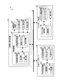
- FIG. 1 is a schematic diagram illustrating an overall configuration of an X-ray thickness measurement system according to an embodiment.
- FIG. 2 is a block diagram showing the configuration of the control system of the X-ray thickness measurement system.
- FIG. 3A is a graph showing an example of the tube voltage value TV of measurement information.
- FIG. 3B is a graph showing an example of the tube current value TC of the measurement information.
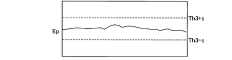
- FIG. 3C is a graph illustrating an example of the drive voltage value Ep of the measurement information.
- FIG. 3D is a graph illustrating an example of the drive current value Ip of the measurement information.
- FIG. 3E is a graph illustrating an example of a detection value Dv of measurement information.
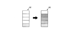
- FIG. 4 is a diagram illustrating an example of a warning image output from the maintenance device.
- FIG. 4 is a diagram illustrating an example of a warning image output from the maintenance device.
- FIG. 5 is a flowchart of the measurement process executed by the control-side processing unit of the thickness measuring apparatus.
- FIG. 6 is a flowchart of the sign process executed by the sign side processing unit of the sign data server.
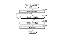
- FIG. 7 is a flowchart of maintenance processing executed by the maintenance-side processing unit of the maintenance device.
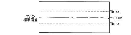
- FIG. 8A is a graph of the standard deviation of the tube voltage value TV of measurement information.
- FIG. 8B is a graph of the standard deviation of the tube current value TC of the measurement information.
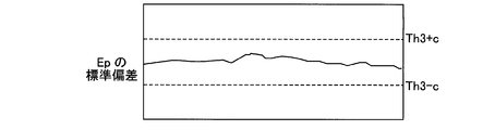
- FIG. 8C is a graph of the standard deviation of the drive voltage value Ep of the measurement information.
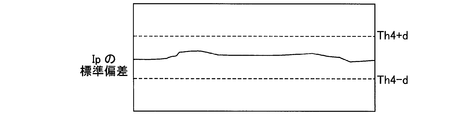
- FIG. 8D is a graph of the standard deviation of the drive current value Ip of the measurement information.
- FIG. 8E is a graph of the standard deviation of the detection value Dv of the measurement information.
- FIG. 9 is a graph of the product of variance and kurtosis of detected values included in measurement information.
- FIG. 1 is a schematic diagram illustrating an overall configuration of an X-ray thickness measurement system 10 according to an embodiment.
- the X-ray thickness measurement system 10 measures the thickness of the measurement object 90 with the X-ray thickness measurement device 12 and generates and accumulates predictive data necessary for diagnosing the abnormality of the X-ray thickness measurement device 12. An abnormality of the measuring device 12 is diagnosed.
- the X-ray thickness measurement system 10 includes an X-ray thickness measurement device 12, a predictive data server 14, a maintenance device 16, and a network 18.
- the network 18 may be a LAN (Local Area Network) or the like that connects the X-ray thickness measuring device 12, the predictive data server 14, and the maintenance device 16 so that information can be transmitted and received between them.
- LAN Local Area Network
- the X-ray thickness measurement apparatus 12 irradiates the measurement object 90 that is the object of thickness measurement with X-rays, and measures the thickness of the measurement object 90 based on the amount of X-rays that have passed through the measurement object 90.
- the X-ray thickness measurement device 12 includes a measurement unit 20, an X-ray control power source 22, and a control device 24.
- the measurement unit 20 irradiates the measurement target 90 with X-rays and outputs at least one of a detection voltage or a detection current for calculating the thickness of the measurement target 90 to the control device 24 as a detection value.
- the measurement unit 20 includes a holding unit 26, a transformer 28, an X-ray generator 30, a detector 32, an output detection unit 34, a drive detection unit 42, and a tube detection unit 44.
- the holding unit 26 holds a transformer 28, an X-ray generator 30, a detector 32, and an output detection unit 34.
- the transformer 28 transforms (for example, boosts) the electric power output from the X-ray control power supply 22 and supplies it to the filament 38 of the X-ray generator 30 described later.
- the X-ray generator 30 generates X-rays by the power supplied from the X-ray control power source 22 and irradiates the measurement object 90.
- the X-ray generator 30 includes an X-ray tube 36, a filament 38, and a target 40.
- the X-ray tube 36 is, for example, a sealed tube that maintains the inside in a vacuum state.
- the X-ray tube 36 accommodates and holds the filament 38 and the target 40 therein.
- the filament 38 emits electrons to the target 40 by the electric power supplied from the X-ray control power supply 22 via the transformer 28.
- the target 40 irradiates the measurement target 90 with X-rays by collision of electrons emitted from the filament 38.
- the detector 32 is disposed at a position facing the X-ray generator 30 with the measurement object 90 interposed therebetween.
- the detector 32 outputs at least one of a detection voltage and a detection current corresponding to the intensity of the X-rays irradiated by the X-ray generator 30 and passed through the measurement object 90 to the output detection unit 34 as a detection signal.
- the detector 32 may be, for example, an ionization chamber that outputs a detection voltage and a detection current corresponding to incident X-rays.
- the output detection unit 34 converts the detection signal output from the detector 32 and outputs the detection signal to the control device 24.
- the output detection unit 34 may include an AD converter and the like, and may output a value obtained by digitally converting an analog detection signal as a detection value for calculating the thickness of the measurement target 90.
- the X-ray control power supply 22 is an example of a power supply, and supplies power supplied to the filament 38 of the X-ray generator 30 via the transformer 28 based on a power supply control signal from the control device 24.
- the X-ray control power source 22 may be connected to an external power source such as a commercial power source, for example.
- the drive detection unit 42 detects a drive voltage value and a drive current value.
- the drive voltage value is a voltage value on the primary side of the transformer 28 and is a voltage value of power supplied from the X-ray control power supply 22.
- the drive current value is a value of a current flowing on the primary side of the transformer 28 and is a value of a current of power supplied from the X-ray control power supply 22.
- the drive detection unit 42 outputs the detected drive voltage value and drive current value to the control device 24.
- the tube detector 44 detects a tube voltage value and a tube current value.
- the tube voltage value is a voltage value on the secondary side of the transformer 28 and is a voltage value of power supplied to the filament 38.
- the tube current value is a value of a current flowing through the secondary side of the X-ray generator 30 and is a value of a current of power supplied to the filament 38.
- the tube detection unit 44 outputs the detected tube voltage value and tube current value to the control device 24.
- the control device 24 is responsible for overall control of the X-ray thickness measuring device 12.
- the control device 24 may be a computer used by an operator or the like who measures the thickness of the measurement object 90 using the X-ray thickness measurement device 12.
- the control device 24 calculates the thickness of the measurement target 90 based on the detection value acquired from the output detection unit 34.
- the control device 24 outputs to the X-ray control power supply 22 a power supply control signal that indicates a drive voltage value corresponding to the tube voltage value of the power supplied to the X-ray generator 30.
- the control device 24 may generate a power supply control signal that indicates a drive voltage value set based on the tube voltage value acquired from the tube detection unit 44.
- the control device 24 outputs the measurement information 56 including the detection value, the drive voltage value, the drive current value, the tube voltage value, and the tube current value acquired from the output detection unit 34, the drive detection unit 42, and the tube detection unit 44 to the network 18. To do.
- the control device 24 may output the measurement information 56 by broadcast, for example.
- the sign data server 14 repeatedly acquires the measurement information 56 from the control device 24 a plurality of times, and stores data indicating a sign of abnormality of the X-ray thickness measurement apparatus 12 generated from the plurality of measurement information 56 (hereinafter, sign data). And accumulate.
- the sign data server 14 outputs the sign data in response to a request from the maintenance device 16.
- the maintenance device 16 is a computer used by, for example, a maintenance person who maintains the X-ray thickness measuring device 12.
- the maintenance device 16 diagnoses an abnormality of the X-ray thickness measuring device 12 based on the predictive data acquired from the predictive data server 14 and outputs the diagnosis result as an image or the like.
- FIG. 2 is a block diagram showing the configuration of the control system of the X-ray thickness measurement system 10.
- the control device 24 includes a control side processing unit 46 and a control side storage unit 48.
- the control side processing unit 46 is responsible for overall control of the X-ray thickness measuring apparatus 12.
- the control-side processing unit 46 may be a hardware processor such as a CPU (Central Processing Unit) and a GPU (Graphics Processing Unit) that execute arithmetic processing and the like.
- the control processing unit 46 reads the program stored in the control storage unit 48 and develops the read program in the control storage unit 48 to execute various arithmetic processes.
- the control processing unit 46 reads the measurement program 54 and functions as the reception unit 50 and the calculation unit 52.
- Part or all of the reception unit 50 and the calculation unit 52 may be configured by hardware such as a circuit including an ASIC (Application Specific Integrated Circuit) or an FPGA (Field-Programmable Gate Array).
- ASIC Application Specific Integrated Circuit
- FPGA Field-Programmable Gate Array
- the reception unit 50 receives the measurement information 56 and outputs it to the calculation unit 52.
- the reception unit 50 receives, for example, the detection value from the output detection unit 34, the drive voltage value and the drive current value from the drive detection unit 42, and the tube voltage value and the tube current value from the tube detection unit 44 as the measurement information 56.
- the calculation unit 52 calculates the thickness of the measurement target 90 based on the measurement information 56 and controls the X-ray thickness measurement apparatus 12. For example, the calculation unit 52 calculates the thickness of the measurement target 90 based on the detection value.
- the calculation unit 52 generates and outputs a power supply control signal for instructing the drive voltage value to the X-ray control power supply 22 so that the tube voltage value and the tube current value become preset voltage values.
- the calculation unit 52 may output the measurement information 56 to the network 18 by broadcasting.
- the control-side storage unit 48 includes a main storage device and an auxiliary storage device such as a ROM (Read Only Memory), a RAM (Random Access Memory), and an HDD (Hard Disk Drive).
- the control-side storage unit 48 stores a measurement program 54 executed by the control-side processing unit 46, measurement information 56 acquired for executing the measurement program 54, and the like.
- the measurement program 54 may be provided by being stored in a computer-readable storage medium such as a CD-ROM (Compact Disc Read Only Memory) or a DVD-ROM (Digital Versatile Disc Read Only Memory) or a network such as the Internet. It may be provided via.
- the sign data server 14 includes a sign side processing unit 58 and a sign side storage unit 60.
- the sign side processing unit 58 governs overall control of the sign data server 14.
- the sign side processing unit 58 may be a hardware processor such as a CPU and a GPU.
- the sign side processing unit 58 reads the program stored in the sign side storage unit 60 and develops the read program in the sign side storage unit 60 to execute various arithmetic processes.
- the sign side processing unit 58 reads, for example, the sign program 66 and functions as the acquisition unit 62 and the sign unit 64. Part or all of the acquisition unit 62 and the sign unit 64 may be configured by hardware such as a circuit including an ASIC or FPGA.
- the acquisition unit 62 acquires measurement information 56 including a drive voltage value, a drive current value, a tube voltage value, a tube current value, and a detection value flowing on the network 18 a plurality of times, and outputs the measurement information 56 to the sign unit 64.
- the sign unit 64 generates sign data 68 for diagnosing an abnormality of the X-ray thickness measurement device 12 based on the plurality of pieces of measurement information 56 acquired from the network 18 and stores the sign data 68 in the sign side storage unit 60.
- the sign unit 64 may generate, as the sign data 68, a value obtained by statistically processing a result of comparing a plurality of measurement information 56 and a predetermined threshold value.
- the sign unit 64 accumulates the generated sign data 68 in the sign side storage unit 60.
- the sign unit 64 outputs the accumulated sign data 68 in response to a request from the maintenance device 16.
- the sign unit 64 generates the sign data 68 based on the result of comparing at least one of the drive voltage value, the drive current value, the tube voltage value, the tube current value, and the detection value included in the measurement information 56 with a threshold value. You can do it.
- the sign side storage unit 60 includes a ROM, a RAM, a main storage device such as an HDD, and an auxiliary storage device.
- the sign side storage unit 60 stores the sign program 66 executed by the sign side processing unit 58, the sign data 68 generated by the execution of the sign program 66, and the like.
- the predictor program 66 may be provided by being stored in a computer-readable storage medium such as a CD-ROM or DVD-ROM, or may be provided via a network such as the Internet.
- the maintenance device 16 includes a maintenance-side processing unit 70, a maintenance-side storage unit 72, and a display unit 73.
- the maintenance-side processing unit 70 is responsible for overall control of the maintenance device 16.
- the maintenance processing unit 70 may be a hardware processor such as a CPU and a GPU.
- the maintenance-side processing unit 70 reads the program stored in the maintenance-side storage unit 72 and develops the read program in the maintenance-side storage unit 72, thereby executing various arithmetic processes.
- the maintenance processing unit 70 reads the maintenance program 76 and functions as the diagnosis unit 74.
- Part or all of the diagnosis unit 74 may be configured by hardware such as a circuit including an ASIC or FPGA.
- the diagnosis unit 74 acquires the sign data 68 output from the sign data server 14 and diagnoses an abnormality of the X-ray thickness measuring apparatus 12 based on the sign data 68.
- the diagnosis unit 74 generates information indicating a warning, for example, an image indicating the warning, and causes the display unit 73 to display the information.
- the maintenance-side storage unit 72 includes a ROM, a RAM, a main storage device such as an HDD, and an auxiliary storage device.
- the maintenance side storage unit 72 stores a maintenance program 76 and the like executed by the maintenance side processing unit 70.
- the maintenance program 76 may be provided by being stored in a computer-readable storage medium such as a CD-ROM or DVD-ROM, or may be provided via a network such as the Internet.
- 3A, 3B, 3C, 3D, and 3E are graphs showing examples of the values TV, TC, Ep, Ip, and Dv of the measurement information 56, respectively.
- the horizontal axis of each graph in FIGS. 3A, 3B, 3C, 3D, and 3E indicates time.
- the graph of FIG. 3A shows the tube voltage value TV.
- the graph of FIG. 3B shows the tube current value TC.
- the graph of FIG. 3C shows the drive voltage value Ep.
- the graph of FIG. 3D shows the drive current value Ip.
- the graph of FIG. 3E shows the detection value Dv.
- 3A, 3B, 3C, 3D, and 3E are values when the drive voltage value Ep is controlled to maintain the tube voltage value TV at 100 kV. is there.
- the acquisition unit 62 acquires the values TV, TC, Ep, Ip, and Dv shown in FIGS. 3A, 3B, 3C, 3D, and 3E output from the control device 24 from the network 18, and sends them to the predictor 64. Output.
- the predictor 64 acquires each value TV, TC, Ep, Ip, Dv, the threshold value set in advance in association with each value TV, TC, Ep, Ip, Dv and each value TV, TC, Ep, Ip , Dv, and predictive data 68 are generated.
- the sign unit 64 determines, for example, whether or not the tube voltage value TV is equal to or higher than the first threshold Th1 + a or equal to or lower than the second threshold Th1-a. For example, when the tube voltage value TV is equal to or greater than the first threshold Th1 + a or equal to or less than the second threshold Th1-a, the predictor 64 increments the tube voltage abnormal value by one.
- the sign unit 64 determines, for example, whether or not the tube current value TC is greater than or equal to the third threshold Th2 + b or less than or equal to the fourth threshold Th2-b. For example, when the tube current value TC is equal to or greater than the third threshold Th2 + b or equal to or less than the fourth threshold Th2-b, the predictor 64 increments the tube current abnormal value by one. For example, in the example shown in FIGS. 3A, 3B, 3C, 3D, and 3E, the predictor 64 has the tube current value TC in the region surrounded by the broken line equal to or greater than the third threshold Th2 + b or the fourth threshold Th2- Since it is 7 times below b, the tube current abnormal value is incremented by 7.
- the predictor 64 determines whether or not the drive voltage value Ep is not less than the fifth threshold Th3 + c or not more than the sixth threshold Th3-c. For example, if the drive voltage value Ep is not less than the fifth threshold Th3 + c or not more than the sixth threshold Th3-c, the predictor 64 increments the drive voltage abnormal value by one.
- the predictor 64 determines whether or not the drive current value Ip is equal to or greater than the seventh threshold Th4 + d or equal to or less than the eighth threshold Th4-d. For example, if the drive current value Ip is not less than the seventh threshold Th4 + d or not more than the eighth threshold Th4-d, the predictor 64 increments the drive current abnormal value by one.
- the predictor 64 determines whether or not the detection value Dv is equal to or greater than the ninth threshold Th5 + e or equal to or less than the tenth threshold Th5-e. For example, when the detected value Dv is equal to or greater than the ninth threshold Th5 + e or equal to or smaller than the tenth threshold Th5-e, the predictor 64 increments the detected abnormal value by one.
- the sign unit 64 generates predictive data 68 including an abnormal tube voltage value, an abnormal tube current value, an abnormal drive voltage value, an abnormal drive current value, and a detected abnormal value.
- the initial values of the tube voltage abnormal value, the tube current abnormal value, the drive voltage abnormal value, the drive current abnormal value, and the detected abnormal value may be zero. Therefore, if the values TV, TC, Ep, Ip, and Dv are within the corresponding threshold ranges, the abnormal value corresponding to the values TV, TC, Ep, Ip, and Dv is zero.
- the above threshold value is an example, and the threshold value may be changed according to the tube voltage value TV, for example. In this case, the threshold value may be stored in the sign side storage unit 60 in association with the tube voltage TV.
- FIG. 4 is a diagram illustrating an example of a warning image 92 output from the maintenance device 16.
- the diagnosis unit 74 of the maintenance device 16 may display the warning image 92 on the display unit 73 based on the predictive data 68 acquired from the predictive data server 14.
- the diagnosis unit 74 diagnoses the abnormal level based on the abnormal tube voltage value, the abnormal tube current value, the abnormal drive voltage value, the abnormal drive current value, and the detected abnormal value included in the predictive data 68.
- the diagnosis unit 74 may set the number of abnormal values other than 0 among the abnormal tube voltage value, the abnormal tube current value, the abnormal drive voltage value, the abnormal drive current value, and the detected abnormal value as an abnormal level. In this case, the diagnosis unit 74 sets an abnormal level in a range from 0 level to 5 level.
- the diagnosis unit 74 may set an abnormality level based on a predetermined abnormality determination threshold. In this case, the diagnosis unit 74 sets the number of abnormal values equal to or higher than the abnormality determination threshold among the abnormal tube voltage value, abnormal tube current value, abnormal drive voltage value, abnormal drive current value, and detected abnormal value as an abnormal level. May be set.
- the diagnosis unit 74 may generate a warning image 92 according to the abnormal level. For example, when the abnormal level is 1, the diagnosis unit 74 may generate a warning image 92 in which the bottom square is colored among the five squares arranged as shown on the left side of FIG. When the abnormal level is 4, the diagnosis unit 74 may generate a warning image 92 in which the four squares from the bottom are colored out of the five squares arranged. The diagnosis unit 74 may change the color for each square. The diagnosis unit 74 may cause the display unit 73 to display a warning image 92 generated according to the abnormality level.
- FIG. 5 is a flowchart of the measurement process executed by the control-side processing unit 46 of the X-ray thickness measurement apparatus 12.
- the control processing unit 46 executes the measurement process by reading the measurement program 54.
- the reception unit 50 of the control side processing unit 46 acquires the tube voltage value TV and the tube current value TC from the tube detection unit 44 and outputs them to the calculation unit 52 (S102). .
- the receiving unit 50 acquires the drive voltage value Ep and the drive current value Ip from the drive detection unit 42 and outputs them to the calculation unit 52 (S104).
- the receiving unit 50 compares the tube voltage value TV with the set voltage value and controls the drive voltage value Ep (S106). For example, if the tube voltage value TV is lower than the set voltage value, the receiving unit 50 outputs a power supply control signal indicating a voltage value higher than the acquired drive voltage value Ep to the X-ray control power supply 22, and the tube voltage value TV.
- a power supply control signal indicating a voltage value lower than the acquired drive voltage value Ep is output to the X-ray control power supply 22.
- the X-ray control power supply 22 changes the drive voltage value Ep to the voltage value indicated by the acquired power supply control signal, and supplies power to the X-ray generator 30.
- the reception unit 50 acquires the detection value Dv from the output detection unit 34 and outputs it to the calculation unit 52 (S108).
- the calculation unit 52 calculates the thickness of the measurement target 90 based on the detection value Dv (S110).
- the calculation unit 52 outputs measurement information 56 including the drive voltage value Ep, the drive current value Ip, the tube voltage value TV, the tube current value TC, and the detection value Dv to the network 18 (S112). Thereafter, the control-side processing unit 46 repeats step S102 and subsequent steps.
- FIG. 6 is a flowchart of the sign process executed by the sign side processing unit 58 of the sign data server 14.
- the sign side processing unit 58 executes the sign process by reading the sign program 66.
- the acquisition unit 62 acquires the measurement information 56 from the network 18 and outputs the measurement information 56 to the sign unit 64 (S132).
- the sign unit 64 generates the sign data 68 (S134).
- the predictor 64 compares, for example, each value TV, TC, Ep, Ip, Dv included in the measurement information 56 with a threshold value to determine whether each value TV, TC, Ep, Ip, Dv is an abnormal value.
- the prediction data 68 including the number of abnormal values is generated.
- the sign unit 64 stores the generated sign data 68 in the sign side storage unit 60 (S136).
- the sign unit 64 determines whether a request for the sign data 68 has been acquired (S138).
- step S132 When the sign unit 64 determines that the request for the sign data 68 has not been acquired (S138: No), the sign side processing unit 58 repeats step S132 and subsequent steps.
- the predictor 64 determines that the request for the predictor data 68 has been acquired (S138: Yes)
- the predictor 64 outputs the predictor data 68 to the network 18 (S140). After this, the sign side processing unit 58 repeats step S132 and subsequent steps.
- FIG. 7 is a flowchart of maintenance processing executed by the maintenance-side processing unit 70 of the maintenance device 16.
- the maintenance processing unit 70 executes the maintenance process by reading the maintenance program 76.
- the diagnosis unit 74 outputs a request for the predictive data 68 to the network 18 (S152).
- the diagnosis unit 74 determines whether or not the predictive data 68 has been acquired (S154).
- the diagnosis unit 74 is in a standby state until the sign data 68 is acquired (S154: No).
- the diagnosis unit 74 diagnoses an abnormality of the X-ray thickness measurement apparatus 12 based on the number of abnormal values included in the sign data 68 and calculates an abnormality level ( S156).
- the diagnosis unit 74 outputs a warning corresponding to the calculated abnormality level, for example, a warning image 92 to the display unit 73 (S158).
- the maintenance-side processing unit 70 repeats step S152 and subsequent steps.
- the predictive data server 14 can generate and store the predictive data 68 for diagnosing an abnormality such as a failure of the X-ray thickness measuring apparatus 12. As a result, the predictive data server 14 can diagnose the abnormality of the X-ray thickness measuring device 12 and reduce the processing load of the control device 24 of the X-ray thickness measuring device 12 and the storage capacity necessary for the diagnosis.
- the sign data server 14 provides the accumulated sign data 68 to the maintenance device 16 in response to a request from the maintenance device 16. Thereby, the predictive data server 14 can realize diagnosis of abnormality of the X-ray thickness measuring device 12 in the maintenance device 16.
- the sign unit 64 of the second embodiment generates the sign data 68 based on the result of comparing the standard deviation of each value TV, TC, Ep, Ip, and Dv with a threshold value.
- 8A, 8B, 8C, 8, 8D, and 8E are graphs of standard deviations of the values TV, TC, Ep, Ip, and Dv included in the measurement information 56, respectively.
- the graph of FIG. 8A shows the standard deviation of the tube voltage value TV.
- the graph of FIG. 8B shows the standard deviation of the tube current value TC.
- the graph of FIG. 8C shows the standard deviation of the drive voltage value Ep.
- FIGS. 8A, 8B, 8C, 8D, and 8E show the standard deviation of the drive current value Ip.
- the graph of FIG. 8E shows the standard deviation of the detected value Dv.
- the standard deviation of each value TV, TC, Ep, Ip, and Dv in FIGS. 8A, 8B, 8C, 8D, and 8E is when the drive voltage value Ep is controlled to maintain the tube voltage value TV at 100 kV. Is the value of
- the acquisition unit 62 acquires the values TV, TC, Ep, Ip, and Dv shown in FIGS. 8A, 8B, 8C, 8D, and 8E output from the control device 24 from the network 18 and sends them to the sign unit 64. Output.
- the predictor 64 acquires each value TV, TC, Ep, Ip, and Dv, it calculates a standard deviation of each value TV, TC, Ep, Ip, and Dv.
- the sign unit 64 generates the sign data 68 based on a result of comparing a standard threshold with a preset threshold value associated with the standard deviation.
- the predictor 64 compares the threshold with the standard deviation of at least one of the drive voltage value Ep, the drive current value Ip, the tube voltage value TV, the tube current value TC, and the detection value Dv included in the measurement information 56. Based on the above, the predictive data 68 may be generated.
- the predictor 64 determines whether or not the standard deviation of the tube voltage value TV is equal to or greater than the first threshold Th1 + a or equal to or less than the second threshold Th1-a. For example, if the standard deviation of the tube voltage value TV is not less than the first threshold Th1 + a or not more than the second threshold Th1-a, the predictor 64 increments the tube voltage abnormal value by 1.
- the predictor 64 determines whether or not the standard deviation of the tube current value TC is equal to or greater than the third threshold Th2 + b or equal to or less than the fourth threshold Th2-b. For example, if the standard deviation of the tube current value TC is not less than the third threshold Th2 + b or not more than the fourth threshold Th2-b, the predictor 64 increments the tube current abnormal value by one. For example, in the example shown in FIGS.
- the predictor 64 has a standard deviation of the tube current value TC in the region surrounded by the broken line equal to or greater than the third threshold Th2 + b, or the fourth Since it is twice below the threshold value Th2-b, the tube current abnormal value is incremented by 2.
- the predictor 64 determines whether or not the standard deviation of the drive voltage value Ep is equal to or greater than the fifth threshold Th3 + c or equal to or less than the sixth threshold Th3-c. For example, if the standard deviation of the drive voltage value Ep is not less than the fifth threshold Th3 + c or not more than the sixth threshold Th3-c, the predictor 64 increments the drive voltage abnormal value by one.
- the predictor 64 determines whether or not the standard deviation of the drive current value Ip is greater than or equal to the seventh threshold Th4 + d or less than or equal to the eighth threshold Th4-d. For example, if the standard deviation of the drive current value Ip is greater than or equal to the seventh threshold Th4 + d or less than or equal to the eighth threshold Th4-d, the predictor 64 increments the drive current abnormal value by one.
- the predictor 64 determines whether or not the standard deviation of the detection value Dv is greater than or equal to the ninth threshold Th5 + e or less than or equal to the tenth threshold Th5-e. For example, if the standard deviation of the detection value Dv is equal to or larger than the ninth threshold Th5 + e or equal to or smaller than the tenth threshold Th5-e, the predictor 64 increments the detected abnormal value by one.
- the sign unit 64 generates predictive data 68 including an abnormal tube voltage value, an abnormal tube current value, an abnormal drive voltage value, an abnormal drive current value, and a detected abnormal value.
- the initial values of the tube voltage abnormal value, the tube current abnormal value, the drive voltage abnormal value, the drive current abnormal value, and the detected abnormal value may be zero. Therefore, if the standard deviation of the values TV, TC, Ep, Ip, and Dv is within the corresponding threshold range, the abnormal value corresponding to the standard deviation of the values TV, TC, Ep, Ip, and Dv is 0.
- the predictive data server 14 of the second embodiment generates the predictive data 68 based on the standard deviations of the values TV, TC, Ep, Ip, and Dv included in the measurement information 56.
- the sign data server 14 can generate the sign data 68 that can reduce misdiagnosis of the abnormality of the X-ray thickness measurement device 12 based on the short time error of the measurement information 56 and is necessary for storing the sign data 68.
- the storage capacity can be reduced.
- the sign unit 64 of the third embodiment generates the sign data 68 based on the result of comparison between the threshold value and the product of the variance of the detected value Dv and the kurtosis.
- the sign unit 64 calculates the product of the variance and the kurtosis of the detection value Dv included in the measurement information 56.
- the sign unit 64 may generate the sign data 68 based on the result of comparing the product of the calculated variance and kurtosis and a threshold value.
- FIG. 9 is a graph of the product of the variance of the detected value Dv included in the measurement information 56 and the kurtosis.
- the statistical error with respect to the thickness of the measuring object 90 has a Poisson distribution. Using this statistical error, the nature of the noise is detected.
- the statistical error follows a Poisson distribution, the variance and the kurtosis can be expressed by the following equation using the average value m.
- the product of the variance and the kurtosis of the detected value Dv according to the Poisson distribution is a constant value (that is, 1) regardless of the average value m. Accordingly, the product of the variance of the detected value Dv and the kurtosis is approximately 1 if there is no abnormality in the filament 38 or the like.
- the predictor 64 can detect an abnormality in the filament 38 and the like by comparing the product of the dispersion of the detection value Dv and the kurtosis and the predetermined threshold Th6.
- the sign unit 64 may generate the sign data 68 by incrementing the detected abnormal value by 1 when the product of the variance of the detected value Dv and the kurtosis is equal to or greater than the threshold Th6.
- the sign data server 14 generates the sign data 68 based on the product of the variance of the detected value Dv included in the measurement information 56 and the kurtosis. Thereby, the sign data server 14 can generate the sign data 68 that can reduce misdiagnosis of the abnormality of the X-ray thickness measurement device 12 based on the short time error of the measurement information 56 and is necessary for storing the sign data 68. The storage capacity can be reduced.
- diagnosis unit 74 is provided in the maintenance device 16 different from the sign data server 14 .
- diagnosis unit 74 may be provided in the sign data server 14.
Landscapes
- Physics & Mathematics (AREA)
- General Physics & Mathematics (AREA)
- Health & Medical Sciences (AREA)
- Life Sciences & Earth Sciences (AREA)
- Chemical & Material Sciences (AREA)
- Analytical Chemistry (AREA)
- Biochemistry (AREA)
- General Health & Medical Sciences (AREA)
- Immunology (AREA)
- Pathology (AREA)
- Electromagnetism (AREA)
- Length-Measuring Devices Using Wave Or Particle Radiation (AREA)
Abstract
Selon la présente invention, un générateur de rayons X (30) possède un filament (38) qui est alimenté en électricité par une alimentation électrique (22), et émet des rayons X. Un détecteur de sortie (34) délivre en sortie une valeur de détection pour calculer l'épaisseur d'un sujet en cours de mesure. Un serveur de données de prédiction (14) comprend : une unité d'acquisition (62) et une unité de détermination (64). L'unité d'acquisition (62) acquiert, une pluralité de fois, des informations de mesure comprenant au moins l'une des valeurs suivantes : une valeur de tension d'excitation indiquant la tension fournie par l'alimentation électrique (22); une valeur de courant d'excitation indiquant une valeur de courant fournie par l'alimentation électrique (22); une valeur de tension de tube indiquant une valeur pour la tension fournie au filament (38); une valeur de courant de tube indiquant une valeur pour le courant fourni au filament (38); et une valeur détectée. L'unité de prédiction (64) génère des données de prédiction pour diagnostiquer des anomalies dans le dispositif de mesure d'épaisseur par rayons X (12), sur la base d'informations de mesure acquises par l'unité d'acquisition (62), mémorise ces données de prédiction dans une unité de mémorisation (48) et délivre en sortie lesdites données de prédiction à la demande.
Applications Claiming Priority (2)
| Application Number | Priority Date | Filing Date | Title |
|---|---|---|---|
| JP2018105991 | 2018-06-01 | ||
| JP2018-105991 | 2018-06-01 |
Publications (1)
| Publication Number | Publication Date |
|---|---|
| WO2019230010A1 true WO2019230010A1 (fr) | 2019-12-05 |
Family
ID=68698022
Family Applications (2)
| Application Number | Title | Priority Date | Filing Date |
|---|---|---|---|
| PCT/JP2018/032781 Ceased WO2019230010A1 (fr) | 2018-06-01 | 2018-09-04 | Serveur de données de prédiction et système de mesure d'épaisseur par rayons x |
| PCT/JP2019/002138 Ceased WO2019230040A1 (fr) | 2018-06-01 | 2019-01-23 | Serveur de données de prévision et système de mesure d'épaisseur à rayons x |
Family Applications After (1)
| Application Number | Title | Priority Date | Filing Date |
|---|---|---|---|
| PCT/JP2019/002138 Ceased WO2019230040A1 (fr) | 2018-06-01 | 2019-01-23 | Serveur de données de prévision et système de mesure d'épaisseur à rayons x |
Country Status (3)
| Country | Link |
|---|---|
| CN (1) | CN111051812B (fr) |
| TW (1) | TWI687647B (fr) |
| WO (2) | WO2019230010A1 (fr) |
Cited By (1)
| Publication number | Priority date | Publication date | Assignee | Title |
|---|---|---|---|---|
| JP6983966B1 (ja) * | 2020-09-16 | 2021-12-17 | 株式会社東芝 | 厚み測定装置 |
Families Citing this family (4)
| Publication number | Priority date | Publication date | Assignee | Title |
|---|---|---|---|---|
| KR102385159B1 (ko) * | 2018-06-01 | 2022-04-12 | 가부시끼가이샤 도시바 | 예조 데이터 서버 및 x선 두께 측정 시스템 |
| TWI752533B (zh) * | 2020-03-10 | 2022-01-11 | 日商東芝股份有限公司 | 維護裝置 |
| DE102020112651A1 (de) | 2020-05-11 | 2021-11-11 | Volume Graphics Gmbh | Computerimplementiertes Verfahren zur Zustandsüberwachung einer Vorrichtung zur Untersuchung von Objekten |
| JP2022094017A (ja) * | 2020-12-14 | 2022-06-24 | トヨタ自動車株式会社 | 車載システム |
Citations (6)
| Publication number | Priority date | Publication date | Assignee | Title |
|---|---|---|---|---|
| JPS4929666A (fr) * | 1972-07-11 | 1974-03-16 | ||
| JPH04201963A (ja) * | 1990-11-30 | 1992-07-22 | Mitsubishi Electric Corp | 昇降機の遠隔監視制御装置 |
| US5418830A (en) * | 1992-05-15 | 1995-05-23 | Scan-Tech S.A. | Radiometric thickness measurement gage |
| JPH0864388A (ja) * | 1994-08-24 | 1996-03-08 | Toshiba Corp | X線高電圧装置 |
| JP2002100498A (ja) * | 2000-09-21 | 2002-04-05 | Shimadzu Corp | X線診断装置 |
| JP2018032561A (ja) * | 2016-08-25 | 2018-03-01 | 株式会社ジョブ | X線装置およびx線装置の制御方法 |
Family Cites Families (10)
| Publication number | Priority date | Publication date | Assignee | Title |
|---|---|---|---|---|
| JPS5958798A (ja) * | 1982-09-28 | 1984-04-04 | Toshiba Corp | X線管の劣化判定装置 |
| US5351203A (en) * | 1992-08-03 | 1994-09-27 | Bethlehem Steel Corporation | Online tomographic gauging of sheet metal |
| CN102564361B (zh) * | 2011-11-18 | 2013-10-23 | 北京金自天正智能控制股份有限公司 | 一种射线式测厚仪及其校正方法 |
| JP2013156137A (ja) * | 2012-01-30 | 2013-08-15 | Toshiba Corp | 厚さ測定装置、厚さ測定方法及び制御プログラム |
| EP2843362A4 (fr) * | 2012-04-25 | 2015-12-02 | Nippon Steel & Sumitomo Metal Corp | PROCÉDÉ ET DISPOSITIF PERMETTANT DE DÉTERMINER L'ÉPAISSEUR D'UNE PHASE D'UN ALLIAGE DE Fe-Zn D'UNE FEUILLE D'ACIER GALVANISÉ PAR IMMERSION À CHAUD |
| JP6122796B2 (ja) * | 2014-02-24 | 2017-04-26 | 株式会社東芝 | X線厚さ計 |
| JP2016017823A (ja) * | 2014-07-08 | 2016-02-01 | 株式会社日立ハイテクサイエンス | X線分析用試料板及び蛍光x線分析装置 |
| JP6888905B2 (ja) * | 2015-12-10 | 2021-06-18 | 株式会社東芝 | 検出信号におけるa/dコンバータの雑音を低減した厚み計装置 |
| JP2017215173A (ja) * | 2016-05-30 | 2017-12-07 | 株式会社東芝 | 厚さ測定装置 |
| JP6640769B2 (ja) * | 2017-02-22 | 2020-02-05 | 株式会社日立製作所 | 情報処理装置、モビリティデータ収集システム |
-
2018
- 2018-09-04 WO PCT/JP2018/032781 patent/WO2019230010A1/fr not_active Ceased
-
2019
- 2019-01-23 CN CN201980004190.5A patent/CN111051812B/zh active Active
- 2019-01-23 WO PCT/JP2019/002138 patent/WO2019230040A1/fr not_active Ceased
- 2019-03-26 TW TW108110392A patent/TWI687647B/zh active
Patent Citations (6)
| Publication number | Priority date | Publication date | Assignee | Title |
|---|---|---|---|---|
| JPS4929666A (fr) * | 1972-07-11 | 1974-03-16 | ||
| JPH04201963A (ja) * | 1990-11-30 | 1992-07-22 | Mitsubishi Electric Corp | 昇降機の遠隔監視制御装置 |
| US5418830A (en) * | 1992-05-15 | 1995-05-23 | Scan-Tech S.A. | Radiometric thickness measurement gage |
| JPH0864388A (ja) * | 1994-08-24 | 1996-03-08 | Toshiba Corp | X線高電圧装置 |
| JP2002100498A (ja) * | 2000-09-21 | 2002-04-05 | Shimadzu Corp | X線診断装置 |
| JP2018032561A (ja) * | 2016-08-25 | 2018-03-01 | 株式会社ジョブ | X線装置およびx線装置の制御方法 |
Cited By (3)
| Publication number | Priority date | Publication date | Assignee | Title |
|---|---|---|---|---|
| JP6983966B1 (ja) * | 2020-09-16 | 2021-12-17 | 株式会社東芝 | 厚み測定装置 |
| WO2022059246A1 (fr) * | 2020-09-16 | 2022-03-24 | 株式会社東芝 | Dispositif de mesure d'épaisseur |
| JP2022049550A (ja) * | 2020-09-16 | 2022-03-29 | 株式会社東芝 | 厚み測定装置 |
Also Published As
| Publication number | Publication date |
|---|---|
| CN111051812A (zh) | 2020-04-21 |
| TWI687647B (zh) | 2020-03-11 |
| CN111051812B (zh) | 2021-06-18 |
| WO2019230040A1 (fr) | 2019-12-05 |
| TW202004127A (zh) | 2020-01-16 |
Similar Documents
| Publication | Publication Date | Title |
|---|---|---|
| WO2019230010A1 (fr) | Serveur de données de prédiction et système de mesure d'épaisseur par rayons x | |
| CN105939667B (zh) | 用于生成谱计算机断层摄影投影数据的系统 | |
| CN108158597B (zh) | 确定原始x射线能量数据的方法、装置及ct设备 | |
| JP6494274B2 (ja) | 放射線撮影装置、放射線撮影システム、撮影制御装置、撮影制御方法およびプログラム | |
| US11199637B2 (en) | Radiation imaging apparatus, radiation imaging system, control method of radiation imaging apparatus, and non-transitory computer-readable storage medium | |
| CN101996344A (zh) | 计数光子的系统和方法 | |
| JP2020525151A5 (fr) | ||
| JP2023145796A (ja) | X線コンピュータ断層撮影装置 | |
| JP2014138654A (ja) | X線画像診断装置 | |
| EP2944257B1 (fr) | Appareil d'imagerie radiologique, procédé de détermination de l'irradiation de rayonnement et support de stockage | |
| JP5280172B2 (ja) | X線ct装置 | |
| US11119059B2 (en) | Semiconductor defect inspection apparatus and semiconductor defect inspection method | |
| WO2017093045A1 (fr) | Détermination d'état d'un tube à rayons x d'un système à rayons x | |
| JP6585325B1 (ja) | 予兆データサーバ及びx線厚み測定システム | |
| CN106932829B (zh) | 放射线人体检查方法和放射线人体检查系统 | |
| JP2020113445A (ja) | 医用システム及びx線コンピュータ断層撮影装置 | |
| US10895652B2 (en) | Object radiography apparatus and method for determining a state of an object radiography apparatus | |
| EP4430924B1 (fr) | Surveillance de l'état d'un tube à rayons x | |
| JP5413283B2 (ja) | 焦点ズレ検出装置、焦点ズレ検出方法およびプログラム | |
| US11599990B2 (en) | Deterioration determination method and deterioration determination device for industrial x-ray imaging apparatus | |
| JP4680096B2 (ja) | 物品検査システム | |
| JP4948855B2 (ja) | 物品選別装置 | |
| CN113375606B (zh) | 维护装置 | |
| JP7195050B2 (ja) | 放射線検査装置 | |
| US20230204522A1 (en) | Radiation imaging apparatus, image processing apparatus, operation method for radiation imaging apparatus, and non-transitory computer readable storage medium |
Legal Events
| Date | Code | Title | Description |
|---|---|---|---|
| 121 | Ep: the epo has been informed by wipo that ep was designated in this application |
Ref document number: 18920339 Country of ref document: EP Kind code of ref document: A1 |
|
| NENP | Non-entry into the national phase |
Ref country code: DE |
|
| 122 | Ep: pct application non-entry in european phase |
Ref document number: 18920339 Country of ref document: EP Kind code of ref document: A1 |