WO2019230165A1 - 液体燃料噴射器 - Google Patents
液体燃料噴射器 Download PDFInfo
- Publication number
- WO2019230165A1 WO2019230165A1 PCT/JP2019/013074 JP2019013074W WO2019230165A1 WO 2019230165 A1 WO2019230165 A1 WO 2019230165A1 JP 2019013074 W JP2019013074 W JP 2019013074W WO 2019230165 A1 WO2019230165 A1 WO 2019230165A1
- Authority
- WO
- WIPO (PCT)
- Prior art keywords
- swirler
- liquid fuel
- fuel injector
- inclination angle
- working surface
- Prior art date
- Legal status (The legal status is an assumption and is not a legal conclusion. Google has not performed a legal analysis and makes no representation as to the accuracy of the status listed.)
- Ceased
Links
Images


Classifications
-
- F—MECHANICAL ENGINEERING; LIGHTING; HEATING; WEAPONS; BLASTING
- F23—COMBUSTION APPARATUS; COMBUSTION PROCESSES
- F23R—GENERATING COMBUSTION PRODUCTS OF HIGH PRESSURE OR HIGH VELOCITY, e.g. GAS-TURBINE COMBUSTION CHAMBERS
- F23R3/00—Continuous combustion chambers using liquid or gaseous fuel
- F23R3/02—Continuous combustion chambers using liquid or gaseous fuel characterised by the air-flow or gas-flow configuration
- F23R3/04—Air inlet arrangements
- F23R3/10—Air inlet arrangements for primary air
- F23R3/12—Air inlet arrangements for primary air inducing a vortex
- F23R3/14—Air inlet arrangements for primary air inducing a vortex by using swirl vanes
-
- F—MECHANICAL ENGINEERING; LIGHTING; HEATING; WEAPONS; BLASTING
- F23—COMBUSTION APPARATUS; COMBUSTION PROCESSES
- F23D—BURNERS
- F23D11/00—Burners using a direct spraying action of liquid droplets or vaporised liquid into the combustion space
- F23D11/10—Burners using a direct spraying action of liquid droplets or vaporised liquid into the combustion space the spraying being induced by a gaseous medium, e.g. water vapour
-
- F—MECHANICAL ENGINEERING; LIGHTING; HEATING; WEAPONS; BLASTING
- F23—COMBUSTION APPARATUS; COMBUSTION PROCESSES
- F23D—BURNERS
- F23D11/00—Burners using a direct spraying action of liquid droplets or vaporised liquid into the combustion space
-
- F—MECHANICAL ENGINEERING; LIGHTING; HEATING; WEAPONS; BLASTING
- F23—COMBUSTION APPARATUS; COMBUSTION PROCESSES
- F23D—BURNERS
- F23D11/00—Burners using a direct spraying action of liquid droplets or vaporised liquid into the combustion space
- F23D11/10—Burners using a direct spraying action of liquid droplets or vaporised liquid into the combustion space the spraying being induced by a gaseous medium, e.g. water vapour
- F23D11/106—Burners using a direct spraying action of liquid droplets or vaporised liquid into the combustion space the spraying being induced by a gaseous medium, e.g. water vapour medium and fuel meeting at the burner outlet
- F23D11/107—Burners using a direct spraying action of liquid droplets or vaporised liquid into the combustion space the spraying being induced by a gaseous medium, e.g. water vapour medium and fuel meeting at the burner outlet at least one of both being subjected to a swirling motion
-
- F—MECHANICAL ENGINEERING; LIGHTING; HEATING; WEAPONS; BLASTING
- F23—COMBUSTION APPARATUS; COMBUSTION PROCESSES
- F23D—BURNERS
- F23D11/00—Burners using a direct spraying action of liquid droplets or vaporised liquid into the combustion space
- F23D11/36—Details
- F23D11/38—Nozzles; Cleaning devices therefor
-
- F—MECHANICAL ENGINEERING; LIGHTING; HEATING; WEAPONS; BLASTING
- F23—COMBUSTION APPARATUS; COMBUSTION PROCESSES
- F23D—BURNERS
- F23D11/00—Burners using a direct spraying action of liquid droplets or vaporised liquid into the combustion space
- F23D11/36—Details
- F23D11/38—Nozzles; Cleaning devices therefor
- F23D11/383—Nozzles; Cleaning devices therefor with swirl means
-
- F—MECHANICAL ENGINEERING; LIGHTING; HEATING; WEAPONS; BLASTING
- F23—COMBUSTION APPARATUS; COMBUSTION PROCESSES
- F23R—GENERATING COMBUSTION PRODUCTS OF HIGH PRESSURE OR HIGH VELOCITY, e.g. GAS-TURBINE COMBUSTION CHAMBERS
- F23R3/00—Continuous combustion chambers using liquid or gaseous fuel
- F23R3/28—Continuous combustion chambers using liquid or gaseous fuel characterised by the fuel supply
-
- F—MECHANICAL ENGINEERING; LIGHTING; HEATING; WEAPONS; BLASTING
- F23—COMBUSTION APPARATUS; COMBUSTION PROCESSES
- F23R—GENERATING COMBUSTION PRODUCTS OF HIGH PRESSURE OR HIGH VELOCITY, e.g. GAS-TURBINE COMBUSTION CHAMBERS
- F23R3/00—Continuous combustion chambers using liquid or gaseous fuel
- F23R3/28—Continuous combustion chambers using liquid or gaseous fuel characterised by the fuel supply
- F23R3/286—Continuous combustion chambers using liquid or gaseous fuel characterised by the fuel supply having fuel-air premixing devices
-
- F—MECHANICAL ENGINEERING; LIGHTING; HEATING; WEAPONS; BLASTING
- F23—COMBUSTION APPARATUS; COMBUSTION PROCESSES
- F23R—GENERATING COMBUSTION PRODUCTS OF HIGH PRESSURE OR HIGH VELOCITY, e.g. GAS-TURBINE COMBUSTION CHAMBERS
- F23R3/00—Continuous combustion chambers using liquid or gaseous fuel
- F23R3/28—Continuous combustion chambers using liquid or gaseous fuel characterised by the fuel supply
- F23R3/30—Continuous combustion chambers using liquid or gaseous fuel characterised by the fuel supply comprising fuel prevapourising devices
-
- F—MECHANICAL ENGINEERING; LIGHTING; HEATING; WEAPONS; BLASTING
- F23—COMBUSTION APPARATUS; COMBUSTION PROCESSES
- F23D—BURNERS
- F23D2900/00—Special features of, or arrangements for burners using fluid fuels or solid fuels suspended in a carrier gas
- F23D2900/11101—Pulverising gas flow impinging on fuel from pre-filming surface, e.g. lip atomizers
Definitions
- the present disclosure relates to a liquid fuel injector, particularly a liquid fuel injected as an annular liquid film, using a shear force acting between a swirling air flow that flows adjacent to the radially inner side and the outer side of the liquid fuel.
- the present invention relates to an air atomization type liquid fuel injector.
- liquid fuel When liquid fuel is burned in a combustor of a gas turbine, it is desirable to atomize the liquid fuel in order to promote vaporization of the liquid fuel and mixing with combustion air.
- the atomization of liquid fuel contributes to the reduction of NOx (nitrogen oxide) and unburned fuel and CO (carbon monoxide) emissions by increasing the speed of the combustion reaction.
- One of the liquid fuel atomization methods is the airflow atomization method. This is a system in which liquid fuel injected in a film shape is atomized by utilizing a shearing force resulting from a speed difference between the liquid fuel and an adjacent air flow.
- Patent Document 1 As a liquid fuel injector adopting an air atomization method, there is one disclosed in Patent Document 1 (FIG. 4).
- This liquid fuel injector utilizes a shearing force that acts on the liquid fuel injected as an annular liquid film from the annular nozzle (40) between the air flow that flows adjacent to the inside and outside in the radial direction. It is configured to atomize.
- the swirlers (31, 32) disposed in the air passages impart a swirl to the air flow.
- a helical wing is usually used as will be described later.
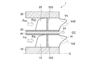
- FIG. 4 is a schematic cross-sectional view showing a main part of a conventional air atomization type liquid fuel injector employing a helical blade as a swirler. In the figure, only the cross section on one side (upper side) with respect to the central axis C is shown.
- the liquid fuel injector 1 includes a cylindrical center body 10 having a central axis C, an annular shroud 30 disposed concentrically on the radially outer side of the center body 10, and a concentric arrangement between the center body 10 and the shroud 30. And a hollow double-cylindrical fuel injector 20 having an annular liquid fuel passage Pf formed therein.
- An annular inner air passage Pai and an outer air passage Pao are formed between the center body 10 and the fuel injector 20, and between the fuel injector 20 and the shroud 30, respectively.
- a plurality of inner swirl vanes 15 and outer swirl vanes 25 are arranged at equal intervals in the circumferential direction in the inner air passage Pai and the outer air passage Pao, respectively.
- the air flows flowing into the inner air passage Pai and the outer air passage Pao are swirled when passing through the inner swirler 15 and the outer swirler 25, respectively. It is given and flows into the combustion chamber CC as a swirling flow having a circumferential velocity component.
- the liquid fuel injected in the form of a film as shown by the arrow Ff in FIG. 4 from the annular liquid fuel passage Pf formed inside the fuel injector 20 has a circumferential velocity component as described above.
- a shearing force due to a speed difference from the air flow flowing out from each of the inner air passage Pai and the outer air passage Pao acts, whereby the liquid fuel is atomized.
- the inner swirler 15 and the outer swirler 25 are both formed as helical blades.
- This helical wing is formed such that the cross sections 15S and 25S in a plane including the central axis C (the paper surface of FIG. 4) both extend in a direction (radial direction) substantially perpendicular to the central axis C.
- the velocity distribution (axis) at the outlet of each air passage The radial distribution of the directional velocity component is Vi and Vo, respectively. These distributions are distributions in which the peak is shifted radially outward as compared with the radial velocity distributions Vi0 and Vo0 in the absence of the helical blade (swirl blade). This is because the air flow is biased radially outward in each air passage due to the centrifugal force acting due to the swirl imparted when passing through the helical blade (swirl blade).
- the velocity distribution Vi has a peak close to the flow Ff of the film-like liquid fuel injected from the fuel injector 20, and thus contributes greatly to atomization of the liquid fuel, but the velocity distribution Vo Since the peak is far away from the film-like liquid fuel flow Ff injected from the fuel injector 20, the contribution to atomization of the liquid fuel is small.
- the air atomization type liquid fuel injector that employs the helical wing having the shape as described above as a swirler does not necessarily contribute greatly to the atomization of the liquid fuel. Therefore, a large flow rate of air is required to achieve the required atomization of the liquid fuel, and the pressure loss generated in the helical blade is increased accordingly. In other words, the level of atomization of the liquid fuel achieved by the same air flow rate (or pressure loss) is lowered.
- the present disclosure has been made in view of the above problems, and an air atomization type capable of achieving the required atomization of liquid fuel with a smaller air flow rate (or smaller pressure loss).
- An object is to provide a liquid fuel injector.
- a liquid fuel injector includes a cylindrical center body having a central axis, an annular shroud disposed concentrically on the radially outer side of the center body, the center body, and the An annular fuel injector that is concentrically disposed between the shroud and has a liquid fuel passage formed therein, and an annular inner air passage formed between the center body and the fuel injector in the circumferential direction.
- a plurality of inner swirlers arranged at regular intervals and having an inner swirler working surface on the upstream side in the air flow direction in the inner air passage, and annular outer air formed between the fuel injector and the shroud
- a plurality of outer swirlers arranged at equal intervals in the circumferential direction in the passage and having an outer swirler acting surface on the upstream side in the air flow direction in the outer air passage.
- An inner swirler working surface profile that is a line of intersection between the inner swirler working surface and a plane that includes the central axis
- an outer swirler that is a line of intersection between the outer swirler working surface and the plane that includes the central axis At least one of the working surface profiles and a part thereof are inclined with respect to a direction perpendicular to the central axis.
- liquid fuel injector of the present disclosure a high level of liquid fuel atomization can be achieved under the same air flow rate (or pressure loss), and the same level of liquid fuel atomization can be achieved. It is possible to obtain an excellent effect that the air flow rate (or pressure loss) necessary for the operation can be kept small.
- FIG. 1 is a schematic overall cross-sectional view of an air atomization type liquid fuel injector according to a first embodiment of the present disclosure. It is a principal part schematic sectional drawing of the air atomization type
- FIG. 1 is a schematic overall cross-sectional view of an air atomization type liquid fuel injector according to a first embodiment of the present disclosure.
- the upstream side and the downstream side in the flow direction of air and liquid fuel which will be described later, are referred to as the front side and the rear side, respectively.
- the liquid fuel injector 100 includes a cylindrical center body 110 having a central axis C, an annular shroud 130 disposed concentrically on the radially outer side of the center body 110, and a concentric arrangement between the center body 110 and the shroud 130. And an annular fuel injector 120 disposed therein.
- the fuel injector 120 includes an annular outer wall and an inner wall, and an annular liquid fuel passage Pf is formed between the two walls.
- a liquid fuel inflow port 120p is formed at the front end of the annular outer wall of the fuel injector 120.
- An annular inner air passage Pai and an outer air passage Pao are formed between the center body 110 and the fuel injector 120 and between the fuel injector 120 and the shroud 130, respectively.
- a plurality of inner swirling blades 115 and outer swirling blades 125 are arranged at regular intervals in the circumferential direction.
- Air flows into the inner air passage Pai and the outer air passage Pao as indicated by arrows Fai and Fao in FIG. 1, respectively, and is swirled when passing through the inner swirler 115 and the outer swirler 125, respectively. It flows into the combustion chamber CC as a swirling flow having a directional velocity component.
- the liquid fuel flows into the annular liquid fuel passage Pf via the liquid fuel inflow port 120p formed at the front end of the outer wall of the fuel injector 120, and from the rear end of the fuel injector 120, 1 is injected into the combustion chamber CC as indicated by the arrow Ff, forming an annular liquid film.
- the injected liquid fuel is subjected to a shearing force due to a speed difference from the air flow flowing out from each of the inner air passage Pai and the outer air passage Pao in a state having the circumferential velocity component as described above.
- the liquid fuel is atomized.
- both the inner swirl wing 115 and the outer swirl wing 125 are formed as helical wings.
- the sections 115S and 125S (see FIG. 2) in the plane including the plane (the paper surface of FIGS. 1 and 2) are formed so as to be inclined with respect to the direction (radial direction) substantially perpendicular to the central axis C. Yes. This point will be described in detail below.
- FIG. 2 is a schematic cross-sectional view showing the main part of the liquid fuel injector 100. In the figure, only the cross section on one side (upper side) with respect to the central axis C is shown.
- the inner swirl vane 115 disposed in the inner air passage Pai has a cross section 115 ⁇ / b> S on a plane including the central axis C (paper surface in FIG. 2) radially outward toward the rear (downstream side). It is inclined (in other words, at least a part of an arbitrary part of the cross section 115S is located on the outer side in the radial direction as compared with a part located in front (upstream side) of the part).
- the inner swirling blade 115 has a surface located upstream, that is, an inner swirling blade working surface having a function of imparting swirling to the air flow, and a plane including the central axis C (paper surface in FIG. 2).
- 115W (hereinafter, referred to as an inner swirl blade working surface profile) 115W is configured to be a straight line or a curve that is inclined (angled) radially outward toward the rear (downstream side).
- the inner swirler inclination angle ⁇ i is an angle of less than 90 ° that takes a positive or negative sign when measured clockwise and counterclockwise from the straight line 115R to the inner swirler working surface profile 115W, and its absolute value
- the sign of ⁇ i is positive, that is, ⁇ i> 0 °, and preferably ⁇ i ⁇ 45 °.
- the cross section 125S in the plane including the central axis C (the paper surface of FIG. 2) is inclined radially inward toward the rear (downstream side).
- at least a part of an arbitrary part of the cross section 125S is located on the radially inner side as compared with a part located forward (upstream side) of the part).
- the outer swirl vane 125 has an upstream surface, that is, an outer swirl blade working surface that has a function of imparting swirl to the air flow, and a plane including the central axis C (the paper surface of FIG. 2).
- 125W (hereinafter, referred to as an outer swirl blade working surface profile)
- 125W is configured to be a straight line or a curve that is inclined (angled) radially inward toward the rear (downstream side).
- the outer swirl blade inclination angle ⁇ o is 90 ° taking a positive or negative sign when measured clockwise and counterclockwise from the straight line 125R to the outer swirler blade working surface profile 125W.
- is preferably 45 ° or more (
- the sign of ⁇ o is negative, that is, ⁇ o ⁇ 0 °, and therefore preferably ⁇ o ⁇ ⁇ 45 °.
- both the inner swirler operating surface profile 115W and the outer swirler operating surface profile 125W are straight lines.
- the angles formed by the tangents of the curves and the straight lines 115R and 125R are defined as an inner swirl blade inclination angle ⁇ i and an outer swirl blade inclination angle ⁇ o, respectively.
- the velocity distribution Vi1 at the outlet of the inner air passage Pai is a distribution in which the peak is shifted radially outward compared to the velocity distribution Vi in the conventional liquid fuel injector 1 (see FIG. 4). Yes.
- This peak shift is due to the fact that the inner swirling blade working surface profile 115W of the inner swirling blade 115 disposed in the inner air passage Pai is inclined radially outward toward the rear (downstream side). .
- the velocity distribution Vo1 at the outlet of the outer air passage Pao is a distribution in which the peak is shifted radially inward compared to the velocity distribution Vo in the conventional liquid fuel injector 1 (see FIG. 4).
- This peak shift is due to the fact that the outer swirler working surface profile 125W of the outer swirler 125 disposed in the outer air passage Pao is inclined radially inward toward the rear (downstream). .
- the liquid fuel injector 100 of the present disclosure a high level of liquid fuel atomization can be achieved under the same air flow rate (or pressure loss), and the same level of liquid fuel atomization can be achieved.
- the air flow (or pressure loss) required to achieve this can be kept small.
- the inner swirler working surface profile 115W is inclined radially outward toward the rear (downstream side), and the outer swirler working surface profile.
- the embodiment in which 125W is inclined inward in the radial direction toward the rear (downstream side) has been described.
- by inclining the inner swirling blade and the outer swirling blade in another manner different effects from those described above can be obtained. Can be obtained.
- FIG. 3A to FIG. 3C are schematic cross-sectional views showing the main parts of an air atomization type liquid fuel injector according to another embodiment of the present disclosure.
- the inner swirler working surface profile 215W is rearward (downstream) in the same manner as the liquid fuel injector 100 according to the first embodiment.
- the outer swirl blade working surface profile 225W is radially outward toward the rear (downstream side) as opposed to the liquid fuel injector 100 of the first embodiment. It is inclined to.
- the signs of the inner swirler inclination angle ⁇ i and the outer swirler inclination angle ⁇ o are both positive, that is, ⁇ i> 0 ° and ⁇ o> 0 °, preferably ⁇ i ⁇ 45 ° and ⁇ o ⁇ 45 °.
- the velocity distribution Vi2 at the outlet of the inner air passage Pai is the same as the velocity distribution Vi1 in the liquid fuel injector 100 of the first embodiment, but the velocity distribution Vo2 at the outlet of the outer air passage Pao has been conventionally changed. Compared with the velocity distribution Vo in the liquid fuel injector 1 (see FIG. 4), the peak is shifted to the outside in the radial direction.
- the level of atomization of the liquid fuel is obtained by utilizing the peak of the velocity distribution Vi2 located very close to the flow of the film-like liquid fuel injected from the fuel injector 220.
- the mixture of air and liquid fuel injected from the liquid fuel injector 200 is centered in the combustion chamber CC using the peak of the velocity distribution Vo2 located near the radially outer end of the outer air passage Pao.
- the outer edge Bo2 and the inner edge Bi2 of the flow of the mixture of air and liquid fuel injected from the liquid fuel injector 200 are indicated by broken lines in FIG. 3A. Although shown, refer to the outer edge Bo2).
- the combustion region in the combustion chamber CC can be adjusted appropriately according to the purpose.
- FIG. 3 when it is required to widely disperse the mixture of the injected air and the liquid fuel in a region near the central axis C in the combustion chamber CC while increasing the level of atomization of the liquid fuel, FIG.
- the outer swirler working surface profile 325W has a diameter toward the rear (downstream side) in the same manner as the liquid fuel injector 100 of the first embodiment.
- the inner swirl blade working surface profile 315W may be inclined inward in the radial direction toward the rear (downstream side), contrary to the liquid fuel injector 100 of the first embodiment.
- the velocity distribution at the exit of the passage (the radial distribution of the axial velocity component) is Vi3 and Vo3, respectively.
- the velocity distribution Vo3 at the outlet of the outer air passage Pao is the same as the velocity distribution Vo1 in the liquid fuel injector 100 of the first embodiment, but the velocity distribution Vi3 at the outlet of the inner air passage Pai has been conventionally Compared with the velocity distribution Vi in the liquid fuel injector 1 (see FIG. 4), the peak shifts radially inward.
- the level of atomization of the liquid fuel is utilized by utilizing the peak of the velocity distribution Vo3 located very close to the flow of the film-like liquid fuel injected from the fuel injector 320.
- the mixture of air and liquid fuel injected from the liquid fuel injector 300 is centered in the combustion chamber CC using the peak of the velocity distribution Vi3 located near the radially inner end of the inner air passage Pai. It can be concentrated in the vicinity of the axis C (in FIG. 3B, the outer edge Bo3 and the inner edge Bi3 of the flow of the mixture of air and liquid fuel injected from the liquid fuel injector 300 are indicated by broken lines. See Bi3).
- the mixture of the injected air and the liquid fuel is widely dispersed in both the region near the central axis C and the region radially outward in the combustion chamber CC.
- the inner swirling blade working surface profile 415W is arranged radially inward toward the rear (downstream side) as in the liquid fuel injector 400 of the fourth embodiment of the present disclosure shown in FIG. 3C.
- the outer swirler working surface profile 425W may be inclined radially outward toward the rear (downstream side).
- the sign of the inner swirler inclination angle ⁇ i is negative, that is, ⁇ i ⁇ 0 °
- the sign of the outer swirler inclination angle ⁇ o is positive, that is, ⁇ o> 0 °. Therefore, preferably ⁇ i ⁇ ⁇ 45 °, ⁇ o ⁇ 45 °.
- the flow of the mixture of air and liquid fuel injected from the liquid fuel injector 400 is directed to the region in the vicinity of the central axis C and radially outward in the combustion chamber CC as indicated by the outer edge Bo4 and the inner edge Bi4. It can be widely distributed in both remote areas.
- the inner swirl vane and the outer swirl vane are each formed with a helical surface whose cross section in a plane including the central axis is inclined with respect to a direction (radial direction) substantially perpendicular to the central axis.
- the liquid fuel injector of the present disclosure is not limited to this. That is, in the liquid fuel injector of the present disclosure, only one of the inner swirler and the outer swirler is the helical blade of the above-described aspect, and the other swirler is a helical blade (that is, The cross section in the plane including the central axis may be a blade formed so as to extend in a direction (radial direction) substantially perpendicular to the central axis C). In other words, in the liquid fuel injector of the present disclosure, at least one of the inner swirl vane and the outer swirl vane is configured as the helical blade of the above-described aspect.
- the liquid fuel injector according to the present disclosure is configured so that the velocity distribution (the radial direction of the axial velocity component in the axial direction) is adjusted through the adjustment of the cross-sectional shape of the swirler in the plane including the central axis.
- the velocity distribution the radial direction of the axial velocity component in the axial direction
- the cross-sectional shape of the swirler in the plane including the central axis.
- a liquid fuel injector includes a cylindrical center body having a central axis, an annular shroud disposed concentrically on the radially outer side of the center body, and between the center body and the shroud. And an annular fuel injector having a liquid fuel passage formed therein, and an annular inner air passage formed between the center body and the fuel injector at regular intervals in the circumferential direction.
- a plurality of inner swirlers disposed on the upstream side in the air flow direction in the inner air passage, and an annular outer air passage formed between the fuel injector and the shroud.
- a plurality of outer swirlers disposed on the upstream side in the air flow direction in the outer air passage and having an outer swirler acting surface on the upstream side of the inner swirler,
- An inner swirl blade working surface profile that is a line of intersection between the work surface and the plane that includes the central axis
- an outer swirler working surface profile that is a line of intersection between the outer swirl blade working surface and the plane that includes the central axis. At least one of them and a part thereof are inclined with respect to a direction perpendicular to the central axis.
- the inner swirler working surface profile and the outer swirler working surface profile are both straight and pass through the upstream end of the inner swirler working surface profile.
- the angle from the straight line extending in the direction perpendicular to the central axis to the inner swirler working surface profile is defined as the inner swirler inclination angle and the direction perpendicular to the central axis through the upstream end of the outer swirler working surface profile.
- the angle from the extending straight line to the outer swirler operating surface profile is referred to as the outer swirler inclination angle.
- these inclination angles are measured clockwise and counterclockwise, they take positive and negative signs, respectively.
- at least one of the absolute value of the inner swirl blade inclination angle and the absolute value of the outer swirl blade inclination angle is greater than 0 °.
- the inner swirler working surface profile and the outer swirler working surface profile are both curved and pass through the upstream end of the inner swirler working surface profile.
- the angle from the straight line extending in the direction perpendicular to the central axis to the tangent line at the inclined portion of the inner swirler working surface profile is the inner swirler inclination angle, the center passing through the upstream end of the outer swirler working surface profile.
- An angle from a straight line extending in a direction perpendicular to the axis to a tangent to the inclined portion of the outer swirler working surface profile is referred to as an outer swirler tilt angle, and these tilt angles are clockwise and counterclockwise.
- the absolute value of the inner swirler inclination angle and the outer swirler inclination angle are At least one of the pair value is greater than 0 °.
- the inner swirl blade inclination angle is larger than 0 °, and the outer swirl blade inclination angle is smaller than 0 °.
- the inner swirl blade inclination angle is 45 ° or more, and the outer swirl blade inclination angle is ⁇ 45 ° or less.
- the inner swirler inclination angle is greater than 0 °
- the outer swirler inclination angle is greater than 0 °
- the inner swirl blade inclination angle is 45 ° or more
- the outer swirl blade inclination angle is 45 ° or more
- the inner swirl blade inclination angle is smaller than 0 °
- the outer swirl blade inclination angle is smaller than 0 °
- the inner swirl blade inclination angle is ⁇ 45 ° or less
- the outer swirl blade inclination angle is ⁇ 45 ° or less
- the inner swirl blade inclination angle is smaller than 0 °, and the outer swirl blade inclination angle is larger than 0 °.
- the inner swirl blade inclination angle is ⁇ 45 ° or less, and the outer swirl blade inclination angle is 45 ° or more.
Landscapes
- Engineering & Computer Science (AREA)
- Chemical & Material Sciences (AREA)
- Combustion & Propulsion (AREA)
- Mechanical Engineering (AREA)
- General Engineering & Computer Science (AREA)
- Fuel-Injection Apparatus (AREA)
Abstract
少ない流量の空気で所要の微粒化を達成できる気流微粒化式液体燃料噴射器を提供する。 液体燃料噴射器(100)は、中心軸(C)を有する円筒状センターボディ(110)と、その外側に同心配置された環状シュラウド(130)と、センターボディとシュラウドの間にこれらと同心配置され、内部に燃料通路が形成された環状燃料噴射体(120)と、センターボディと燃料噴射体の間の内側空気通路(Pai)内で等周期で配置され上流側に内側旋回翼作用面を備える複数の内側旋回翼(115)と、燃料噴射体とシュラウドの間の外側空気通路(Pao)内で等周期で配置され上流側に外側旋回翼作用面を備える複数の外側旋回翼(125)とを備え、内側、外側旋回翼作用面のそれぞれと中心軸を含む平面との交線である内側及び外側旋回翼作用面プロファイル(115W,128W) のうち少なくとも一方及びその一部が、中心軸に垂直な方向に対して傾斜している。
Description
本開示は、液体燃料噴射器、特に、環状の液膜として噴射された液体燃料を、その径方向内側及び外側に隣接して流れる旋回空気流との間に作用する剪断力を利用して微粒化する、気流微粒化式の液体燃料噴射器に関する。
ガスタービンの燃焼器において液体燃料を燃焼させる場合、液体燃料の気化及び燃焼用空気との混合を促進するために、液体燃料を微粒化することが望ましい。液体燃料の微粒化は、燃焼反応の速度を高めることを通じて、NOx(窒素酸化物)、並びに、未燃燃料及びCO(一酸化炭素)の排出量低減にも寄与する。
液体燃料の微粒化方式の一つに、気流微粒化方式がある。これは、膜状に噴射された液体燃料を、これと隣接して流れる空気流との速度差に起因する剪断力を利用して微粒化する方式である。
気流微粒化方式を採用した液体燃料噴射器として、特許文献1(図4)に開示されたものがある。この液体燃料噴射器は、円環状ノズル(40)から環状の液膜として噴射された液体燃料を、その径方向内側及び外側に隣接して流れる空気流との間に作用する剪断力を利用して微粒化するように構成されている。膜状の液体燃料の流れと空気流との速度差を増大させることによって液体燃料の微粒化を促進すると共に、微粒化された液体燃料を周方向に一様に分散させることを目的として、環状の空気通路に配置されたスワーラ(swirler)(31,32)によって、空気流に旋回(swirl)が付与される。このスワーラとしては、通常、後述するようにヘリカル翼が用いられる。
図4は、スワーラとしてヘリカル翼を採用した従来の気流微粒化式液体燃料噴射器の要部を示す概略断面図である。なお、同図においては、中心軸Cを基準として一方側(上側)の断面のみを示している。
液体燃料噴射器1は、中心軸Cを有する円筒状のセンターボディ10と、センターボディ10の径方向外側に同心配置された環状のシュラウド30と、センターボディ10とシュラウド30の間にこれらと同心配置され、内部に環状の液体燃料通路Pfが形成された中空二重円筒状の燃料噴射体20と、を備えている。
センターボディ10と燃料噴射体20の間、燃料噴射体20とシュラウド30の間には、それぞれ環状の内側空気通路Pai、外側空気通路Paoが形成されている。そして、内側空気通路Pai、外側空気通路Paoには、それぞれ複数の内側旋回翼15、外側旋回翼25が、周方向に等間隔で配置されている。
これにより、図4においてそれぞれ矢印Fai及びFaoで示すように内側空気通路Pai及び外側空気通路Paoのそれぞれに流入した空気流は、それぞれ内側旋回翼15及び外側旋回翼25を通過する際に旋回を付与され、周方向速度成分を有する旋回流として燃焼室CC内へ流出する。このとき、燃料噴射体20の内部に形成された環状の液体燃料通路Pfから図4において矢印Ffで示すように膜状に噴射された液体燃料には、上述したように周方向速度成分を有する状態で内側空気通路Pai及び外側空気通路Paoのそれぞれから流出する空気流との速度差に起因する剪断力が作用し、これにより液体燃料が微粒化される。
ところで、上述した従来の気流微粒化式液体燃料噴射器1において、内側旋回翼15及び外側旋回翼25は、いずれも、ヘリカル翼として形成されている。このヘリカル翼は、中心軸Cを含む平面(図4の紙面)における断面15S及び25Sが、いずれも実質的に中心軸Cに垂直な方向(径方向)に延びるものとして形成されている。
このようなヘリカル翼として形成された内側旋回翼15及び外側旋回翼25がそれぞれ配置された内側空気通路Pai及び外側空気通路Paoを空気流が通過する場合、各空気通路の出口における速度分布(軸方向速度成分の径方向分布)は、それぞれVi及びVoのようになる。これらの分布は、ヘリカル翼(旋回翼)が存在しない場合における径方向に対称な速度分布Vi0及びVo0と比較して、そのピークが径方向外側へ偏移した分布となっている。これは、ヘリカル翼(旋回翼)を通過する際に付与される旋回に起因して作用する遠心力の影響で、空気流が各空気通路内で径方向外側に偏るためである。
このうち、速度分布Viは、そのピークが燃料噴射体20から噴射される膜状の液体燃料の流れFfに近いため、液体燃料の微粒化への寄与度が大きいものの、速度分布Voは、そのピークが燃料噴射体20から噴射される膜状の液体燃料の流れFfから大きく離れているため、液体燃料の微粒化への寄与度が小さい。
このように、上述したような形状を有するヘリカル翼をスワーラとして採用した気流微粒化式液体燃料噴射器は、液体燃料の微粒化への寄与度が必ずしも大きくない。そのため、液体燃料の所要の微粒化を達成するために大きな流量の空気が必要となり、これに伴ってヘリカル翼において発生する圧力損失も大きくなってしまう。逆の観点から表現すれば、同一の空気流量(または圧力損失)によって達成される液体燃料の微粒化の水準が下がってしまうことになる。
本開示は、以上のような問題点に鑑みてなされたものであって、より少ない空気流量(または、より小さい圧力損失)によって液体燃料の所要の微粒化を達成することができる気流微粒化式液体燃料噴射器を提供することを目的とする。
上記課題を解決するために、本開示の液体燃料噴射器は、中心軸を有する円筒状のセンターボディと、前記センターボディの径方向外側に同心配置された環状のシュラウドと、前記センターボディと前記シュラウドの間にこれらと同心配置され、内部に液体燃料通路が形成された環状の燃料噴射体と、前記センターボディと前記燃料噴射体の間に形成された環状の内側空気通路内において周方向に等周期で配置され、前記内側空気通路内の空気流れ方向における上流側に内側旋回翼作用面を備える複数の内側旋回翼と、前記燃料噴射体と前記シュラウドの間に形成された環状の外側空気通路内において周方向に等周期で配置され、前記外側空気通路内の空気流れ方向における上流側に外側旋回翼作用面を備える複数の外側旋回翼と、を備え、前記内側旋回翼作用面と前記中心軸を含む平面との交線である内側旋回翼作用面プロファイル、及び、前記外側旋回翼作用面と前記中心軸を含む平面との交線である外側旋回翼作用面プロファイルのうち少なくとも一方及びその一部が、前記中心軸に垂直な方向に対して傾斜している。
本開示の液体燃料噴射器によれば、同一の空気流量(または圧力損失)の下では高い水準の液体燃料微粒化を達成することができ、また、同一水準の液体燃料微粒化を達成するために必要な空気流量(または圧力損失)を小さく抑えることができるという優れた効果を得ることができる。
以下、本開示の実施形態について、図面を参照して詳細に説明する。
図1は、本開示の第1実施形態の気流微粒化式液体燃料噴射器の概略全体断面図である。なお、本明細書においては、後述する空気及び液体燃料の流れ方向における上流側、下流側を、それぞれ前側、後側と称することにする。
液体燃料噴射器100は、中心軸Cを有する円筒状のセンターボディ110と、センターボディ110の径方向外側に同心配置された環状のシュラウド130と、センターボディ110とシュラウド130の間にこれらと同心配置された環状の燃料噴射体120と、を備えている。
燃料噴射体120は、環状の外側壁と内側壁から成っており、これら2つの壁の間には環状の液体燃料通路Pfが形成されている。また、燃料噴射体120の環状の外側壁の前側端部には、液体燃料流入ポート120pが形成されている。
センターボディ110と燃料噴射体120の間、燃料噴射体120とシュラウド130の間には、それぞれ環状の内側空気通路Pai、外側空気通路Paoが形成されている。そして、内側空気通路Pai、外側空気通路Paoには、それぞれ複数の内側旋回翼115、外側旋回翼125が、周方向に等周期で配置されている。
空気は、内側空気通路Pai及び外側空気通路Paoに、図1においてそれぞれ矢印Fai及びFaoで示すように流入し、それぞれ内側旋回翼115及び外側旋回翼125を通過する際に旋回を付与され、周方向速度成分を有する旋回流として燃焼室CC内へ流出する。
一方、液体燃料は、燃料噴射体120の外側壁の前側端部に形成された液体燃料流入ポート120pを経て環状の液体燃料通路Pfに流入し、燃料噴射体120の後側端部から、図1において矢印Ffで示すように燃焼室CC内へ噴射され、環状の液膜を形成する。このとき、噴射された液体燃料には、上述したように周方向速度成分を有する状態で内側空気通路Pai及び外側空気通路Paoのそれぞれから流出する空気流との速度差に起因する剪断力が作用し、これにより液体燃料が微粒化される。
本開示の気流微粒化式液体燃料噴射器100においても、内側旋回翼115及び外側旋回翼125は、いずれも、ヘリカル状の翼として形成されているが、このヘリカル状の翼は、中心軸Cを含む平面(図1及び図2の紙面)における断面115S及び125S(図2参照)が、いずれも実質的に中心軸Cに垂直な方向(径方向)に対して傾斜したものとして形成されている。この点について、以下に詳述する。
図2は、液体燃料噴射器100の要部を示す概略断面図である。なお、同図においては、中心軸Cを基準として一方側(上側)の断面のみを示している。
図2に示すように、内側空気通路Paiに配置された内側旋回翼115は、中心軸Cを含む平面(図2の紙面)における断面115Sが、後方(下流側)へ向かって径方向外側へ傾斜している(換言すれば、断面115Sの任意の部位の少なくとも一部は、当該部位よりも前方(上流側)に位置する部位と比較して径方向外側に位置している)。
図示した実施例において、内側旋回翼115は、上流側に位置する面、即ち空気流に旋回を付与する作用を有する内側旋回翼作用面と、中心軸Cを含む平面(図2の紙面)との交線(以下、内側旋回翼作用面プロファイルという。)115Wが後方(下流側)へ向かって径方向外側へ傾斜する(角度を持つ)直線または曲線となるように構成されている。
そして、当該内側旋回翼作用面プロファイル115Wの前端(上流端)である開始点115iを通って径方向に延びる直線115Rと内側旋回翼作用面プロファイル115Wの少なくとも一部との間には、0°ではない所定の角度、即ち内側旋回翼傾斜角θiが形成されている。
内側旋回翼傾斜角θiは、直線115Rから内側旋回翼作用面プロファイル115Wまで時計回り、反時計回りに計った場合にそれぞれ正、負の符号を取る90°未満の角であり、その絶対値|θi|は45°以上(|θi|≧45°)であることが好ましい。図示した実施例においては、θiの符号は正、即ちθi>0°であるから、好ましくはθi≧45°とされる。
同様に、外側空気通路Paoに配置された外側旋回翼125は、中心軸Cを含む平面(図2の紙面)における断面125Sが、後方(下流側)へ向かって径方向内側へ傾斜している(換言すれば、断面125Sの任意の部位の少なくとも一部は、当該部位よりも前方(上流側)に位置する部位と比較して径方向内側に位置している)。
図示した実施例において、外側旋回翼125は、上流側に位置する面、即ち空気流に旋回を付与する作用を有する外側旋回翼作用面と、中心軸Cを含む平面(図2の紙面)との交線(以下、外側旋回翼作用面プロファイルという。)125Wが後方(下流側)へ向かって径方向内側へ傾斜する(角度を持つ)直線または曲線となるように構成されている。
そして、当該外側旋回翼作用面プロファイル125Wの前端(上流端)である開始点125iを通って径方向に延びる直線125Rと外側旋回翼作用面プロファイル125Wの少なくとも一部との間には、0°ではない所定の角度、即ち外側旋回翼傾斜角θoが形成されている。
外側旋回翼傾斜角θoも、内側旋回翼傾斜角θiと同様に、直線125Rから外側旋回翼作用面プロファイル125Wまで時計回り、反時計回りに計った場合にそれぞれ正、負の符号を取る90°未満の角であり、その絶対値|θo|は45°以上(|θo|≧45°)であることが好ましい。図示した実施例においては、θoの符号は負、即ちθo<0°であるから、好ましくはθo≦-45°とされる。
なお、以上においては、内側旋回翼作用面プロファイル115W及び外側旋回翼作用面プロファイル125Wがいずれも直線であることを想定して説明したが、これらのプロファイルが曲線である場合には、傾斜部分における曲線の接線と直線115R、125Rとのなす角度を、それぞれ内側旋回翼傾斜角θi、外側旋回翼傾斜角θoとする。
以上のように構成された内側旋回翼115及び外側旋回翼125がそれぞれ配置された内側空気通路Pai及び外側空気通路Paoを、それぞれ矢印Fai及びFaoで示すように空気流が通過する場合、各空気通路の出口における速度分布(軸方向速度成分の径方向分布)は、それぞれVi1及びVo1のようになる。
このうち、内側空気通路Paiの出口における速度分布Vi1は、従来の液体燃料噴射器1(図4参照)における速度分布Viと比較して、そのピークが径方向外側へ偏移した分布となっている。このピークの偏移は、内側空気通路Paiに配置された内側旋回翼115の内側旋回翼作用面プロファイル115Wが、後方(下流側)へ向かって径方向外側へ傾斜していることによるものである。
一方、外側空気通路Paoの出口における速度分布Vo1は、従来の液体燃料噴射器1(図4参照)における速度分布Voと比較して、そのピークが径方向内側へ偏移した分布となっている。このピークの偏移は、外側空気通路Paoに配置された外側旋回翼125の外側旋回翼作用面プロファイル125Wが、後方(下流側)へ向かって径方向内側へ傾斜していることによるものである。
これらの速度分布Vi1及びVo1におけるピークは、いずれも、燃料噴射体120から噴射される膜状の液体燃料の流れの極めて近くに位置しているため、液体燃料の微粒化への寄与度が非常に大きくなる。したがって、本開示の液体燃料噴射器100によれば、同一の空気流量(または圧力損失)の下では高い水準の液体燃料微粒化を達成することができ、また、同一水準の液体燃料微粒化を達成するために必要な空気流量(または圧力損失)を小さく抑えることができる。
以上においては、液体燃料の微粒化性能を最大限に高めることを目的として、内側旋回翼作用面プロファイル115Wを後方(下流側)へ向かって径方向外側へ傾斜させると共に、外側旋回翼作用面プロファイル125Wを後方(下流側)へ向かって径方向内側へ傾斜させた実施例について説明したが、内側旋回翼及び外側旋回翼を他の態様で傾斜させることにより、上述したものとは異なる作用効果を得ることができる。
図3A~図3Cは、本開示の他の実施形態の気流微粒化式液体燃料噴射器の要部を示す概略断面図である。
図3Aに示した本開示の第2実施形態の液体燃料噴射器200においては、内側旋回翼作用面プロファイル215Wについては、第1実施形態の液体燃料噴射器100と同様に、後方(下流側)へ向かって径方向外側へ傾斜させている一方で、外側旋回翼作用面プロファイル225Wについては、第1実施形態の液体燃料噴射器100とは逆に、後方(下流側)へ向かって径方向外側へ傾斜させている。この場合、内側旋回翼傾斜角θi及び外側旋回翼傾斜角θoの符号は共に正、即ちθi>0°、θo>0°であるから、好ましくはθi≧45°、θo≧45°とされる。
以上のように構成された内側旋回翼215及び外側旋回翼225がそれぞれ配置された内側空気通路Pai及び外側空気通路Paoを、それぞれ矢印Fai及びFaoで示すように空気流が通過する場合、各空気通路の出口における速度分布(軸方向速度成分の径方向分布)は、それぞれVi2及びVo2のようになる。
このうち、内側空気通路Paiの出口における速度分布Vi2は、第1実施形態の液体燃料噴射器100における速度分布Vi1と同様のものとなるが、外側空気通路Paoの出口における速度分布Vo2は、従来の液体燃料噴射器1(図4参照)における速度分布Voと比較して、そのピークが径方向外側へ偏移した分布となっている。
これらの速度分布Vi2及びVo2を組み合わせることにより、燃料噴射体220から噴射される膜状の液体燃料の流れの極めて近くに位置する速度分布Vi2のピークを利用して、液体燃料の微粒化の水準を高めつつ、外側空気通路Paoの径方向外端近くに位置する速度分布Vo2のピークを利用して、液体燃料噴射器200から噴射される空気と液体燃料の混合物を、燃焼室CC内において中心軸Cから径方向外側へ離れた領域にまで広く分散させることができる(図3Aにおいては、液体燃料噴射器200から噴射される空気と液体燃料の混合物の流れの外縁Bo2及び内縁Bi2を破線で示しているが、このうち外縁Bo2を参照)。
これを利用することにより、燃焼室CC内における燃焼領域を、目的に応じて適宜に調整することが可能となる。
例えば、液体燃料の微粒化の水準を高めつつ、噴射される空気と液体燃料の混合物を、燃焼室CC内において中心軸C近傍の領域に広く分散させることが求められる場合には、図3Bに示す本開示の第3実施形態の液体燃料噴射器300のように、外側旋回翼作用面プロファイル325Wを、第1実施形態の液体燃料噴射器100と同様に、後方(下流側)へ向かって径方向内側へ傾斜させる一方、内側旋回翼作用面プロファイル315Wを、第1実施形態の液体燃料噴射器100とは逆に、後方(下流側)へ向かって径方向内側へ傾斜させればよい。この場合、内側旋回翼傾斜角θi及び外側旋回翼傾斜角θoの符号は共に負、即ちθi<0°、θo<0°であるから、好ましくはθi≦-45°、θo≦-45°とされる。
以上のように構成された内側旋回翼315及び外側旋回翼325がそれぞれ配置された内側空気通路Pai及び外側空気通路Paoを、それぞれ矢印Fai及びFaoで示すように空気流が通過する場合、各空気通路の出口における速度分布(軸方向速度成分の径方向分布)は、それぞれVi3及びVo3のようになる。
このうち、外側空気通路Paoの出口における速度分布Vo3は、第1実施形態の液体燃料噴射器100における速度分布Vo1と同様のものとなるが、内側空気通路Paiの出口における速度分布Vi3は、従来の液体燃料噴射器1(図4参照)における速度分布Viと比較して、そのピークが径方向内側へ偏移した分布となる。
これらの速度分布Vi3及びVo3を組み合わせることにより、燃料噴射体320から噴射される膜状の液体燃料の流れの極めて近くに位置する速度分布Vo3のピークを利用して、液体燃料の微粒化の水準を高めつつ、内側空気通路Paiの径方向内端近くに位置する速度分布Vi3のピークを利用して、液体燃料噴射器300から噴射される空気と液体燃料の混合物を、燃焼室CC内において中心軸Cの近傍に集中させることができる(図3Bにおいては、液体燃料噴射器300から噴射される空気と液体燃料の混合物の流れの外縁Bo3及び内縁Bi3を破線で示しているが、このうち内縁Bi3を参照)。
なお、液体燃料の微粒化の水準を高めることよりも、噴射される空気と液体燃料の混合物を燃焼室CC内において中心軸Cの近傍の領域及び径方向外側へ離れた領域の双方に広く分散させることが求められる場合には、図3Cに示す本開示の第4実施形態の液体燃料噴射器400のように、内側旋回翼作用面プロファイル415Wを、後方(下流側)へ向かって径方向内側へ傾斜させると共に、外側旋回翼作用面プロファイル425Wを、後方(下流側)へ向かって径方向外側へ傾斜させればよい。この場合、内側旋回翼傾斜角θiの符号は負、即ちθi<0°であり、外側旋回翼傾斜角θoの符号は正、即ちθo>0°であるから、好ましくはθi≦-45°、θo≧45°とされる。
これにより、液体燃料噴射器400から噴射される空気と液体燃料の混合物の流れは、その外縁Bo4及び内縁Bi4が示すように、燃焼室CC内において中心軸Cの近傍の領域及び径方向外側へ離れた領域の双方に広く分散させることができる。
なお、以上においては、内側旋回翼及び外側旋回翼が、いずれも、中心軸を含む平面における断面が実質的に中心軸に垂直な方向(径方向)に対して傾斜したものとして形成されたヘリカル状の翼である場合について説明したが、本開示の液体燃料噴射器はこれに限定されない。すなわち、本開示の液体燃料噴射器においては、内側旋回翼及び外側旋回翼のうちいずれか一方の旋回翼のみが上述した態様のヘリカル状の翼であり、他方の旋回翼がヘリカル翼(すなわち、中心軸を含む平面における断面が実質的に中心軸Cに垂直な方向(径方向)に延びるものとして形成された翼)であってもよい。換言すれば、本開示の液体燃料噴射器は、内側旋回翼及び外側旋回翼のうち少なくとも一方が、上述した態様のヘリカル状の翼として構成されている。
以上のように、本開示の液体燃料噴射器は、中心軸を含む平面における旋回翼の断面形状の調整を通じて、当該旋回翼が配置された空気通路内の速度分布(軸方向速度成分の径方向分布)を変化させることにより、液体燃料微粒化の水準向上、及び、噴射される空気と液体燃料の混合物の分散のいずれの目的にも適応させることが可能である。
(本開示の態様)
本開示の第1の態様の液体燃料噴射器は、中心軸を有する円筒状のセンターボディと、前記センターボディの径方向外側に同心配置された環状のシュラウドと、前記センターボディと前記シュラウドの間にこれらと同心配置され、内部に液体燃料通路が形成された環状の燃料噴射体と、前記センターボディと前記燃料噴射体の間に形成された環状の内側空気通路内において周方向に等周期で配置され、前記内側空気通路内の空気流れ方向における上流側に内側旋回翼作用面を備える複数の内側旋回翼と、前記燃料噴射体と前記シュラウドの間に形成された環状の外側空気通路内において周方向に等周期で配置され、前記外側空気通路内の空気流れ方向における上流側に外側旋回翼作用面を備える複数の外側旋回翼と、を備え、前記内側旋回翼作用面と前記中心軸を含む平面との交線である内側旋回翼作用面プロファイル、及び、前記外側旋回翼作用面と前記中心軸を含む平面との交線である外側旋回翼作用面プロファイルのうち少なくとも一方及びその一部が、前記中心軸に垂直な方向に対して傾斜している。
本開示の第1の態様の液体燃料噴射器は、中心軸を有する円筒状のセンターボディと、前記センターボディの径方向外側に同心配置された環状のシュラウドと、前記センターボディと前記シュラウドの間にこれらと同心配置され、内部に液体燃料通路が形成された環状の燃料噴射体と、前記センターボディと前記燃料噴射体の間に形成された環状の内側空気通路内において周方向に等周期で配置され、前記内側空気通路内の空気流れ方向における上流側に内側旋回翼作用面を備える複数の内側旋回翼と、前記燃料噴射体と前記シュラウドの間に形成された環状の外側空気通路内において周方向に等周期で配置され、前記外側空気通路内の空気流れ方向における上流側に外側旋回翼作用面を備える複数の外側旋回翼と、を備え、前記内側旋回翼作用面と前記中心軸を含む平面との交線である内側旋回翼作用面プロファイル、及び、前記外側旋回翼作用面と前記中心軸を含む平面との交線である外側旋回翼作用面プロファイルのうち少なくとも一方及びその一部が、前記中心軸に垂直な方向に対して傾斜している。
本開示の第2の態様の液体燃料噴射器においては、前記内側旋回翼作用面プロファイル及び前記外側旋回翼作用面プロファイルは、いずれも直線であり、前記内側旋回翼作用面プロファイルの上流端を通って前記中心軸に垂直な方向に延びる直線から前記内側旋回翼作用面プロファイルまでの角度を内側旋回翼傾斜角、前記外側旋回翼作用面プロファイルの上流端を通って前記中心軸に垂直な方向に延びる直線から前記外側旋回翼作用面プロファイルまでの角度を外側旋回翼傾斜角と称し、これらの傾斜角を、いずれも、時計回り、反時計回りに計った場合にそれぞれ正、負の符号を取る90°未満の角度と定義するとき、前記内側旋回翼傾斜角の絶対値及び前記外側旋回翼傾斜角の絶対値のうち少なくとも一方が、0°より大きい。
本開示の第3の態様の液体燃料噴射器においては、前記内側旋回翼作用面プロファイル及び前記外側旋回翼作用面プロファイルは、いずれも曲線であり、前記内側旋回翼作用面プロファイルの上流端を通って前記中心軸に垂直な方向に延びる直線から、前記内側旋回翼作用面プロファイルの傾斜部分における接線までの角度を内側旋回翼傾斜角、前記外側旋回翼作用面プロファイルの上流端を通って前記中心軸に垂直な方向に延びる直線から、前記外側旋回翼作用面プロファイルの傾斜部分における接線までの角度を外側旋回翼傾斜角、と称し、これらの傾斜角を、いずれも、時計回り、反時計回りに計った場合にそれぞれ正、負の符号を取る90°未満の角度と定義するとき、前記内側旋回翼傾斜角の絶対値及び前記外側旋回翼傾斜角の絶対値のうち少なくとも一方が、0°より大きい。
本開示の第4の態様の液体燃料噴射器においては、前記内側旋回翼傾斜角は0°より大きく、前記外側旋回翼傾斜角は0°より小さい。
本開示の第5の態様の液体燃料噴射器においては、前記内側旋回翼傾斜角は45°以上であり、前記外側旋回翼傾斜角は-45°以下である。
本開示の第6の態様の液体燃料噴射器においては、前記内側旋回翼傾斜角は0°より大きく、前記外側旋回翼傾斜角は0°より大きい。
本開示の第7の態様の液体燃料噴射器においては、記内側旋回翼傾斜角は45°以上であり、前記外側旋回翼傾斜角は45°以上である。
本開示の第8の態様の液体燃料噴射器においては、前記内側旋回翼傾斜角は0°より小さく、前記外側旋回翼傾斜角は0°より小さい。
本開示の第9の態様の液体燃料噴射器においては、前記内側旋回翼傾斜角は-45°以下であり、前記外側旋回翼傾斜角は-45°以下である。
本開示の第10の態様の液体燃料噴射器においては、前記内側旋回翼傾斜角は0°より小さく、前記外側旋回翼傾斜角は0°より大きい。
本開示の第11の態様の液体燃料噴射器においては、前記内側旋回翼傾斜角は-45°以下であり、前記外側旋回翼傾斜角は45°以上である。
100 液体燃料噴射器
110 センターボディ
115 内側旋回翼
115W 内側旋回翼作用面プロファイル
120 燃料噴射体
125 外側旋回翼
125W 外側旋回翼作用面プロファイル
130 シュラウド
C 中心軸
Pai 内側空気通路
Pao 外側空気通路
Pf 液体燃料通路
θi 内側旋回翼傾斜角
θo 外側旋回翼傾斜角
110 センターボディ
115 内側旋回翼
115W 内側旋回翼作用面プロファイル
120 燃料噴射体
125 外側旋回翼
125W 外側旋回翼作用面プロファイル
130 シュラウド
C 中心軸
Pai 内側空気通路
Pao 外側空気通路
Pf 液体燃料通路
θi 内側旋回翼傾斜角
θo 外側旋回翼傾斜角
Claims (11)
- 中心軸を有する円筒状のセンターボディと、
前記センターボディの径方向外側に同心配置された環状のシュラウドと、
前記センターボディと前記シュラウドの間にこれらと同心配置され、内部に液体燃料通路が形成された環状の燃料噴射体と、
前記センターボディと前記燃料噴射体の間に形成された環状の内側空気通路内において周方向に等周期で配置され、前記内側空気通路内の空気流れ方向における上流側に内側旋回翼作用面を備える複数の内側旋回翼と、
前記燃料噴射体と前記シュラウドの間に形成された環状の外側空気通路内において周方向に等周期で配置され、前記外側空気通路内の空気流れ方向における上流側に外側旋回翼作用面を備える複数の外側旋回翼と、を備え、
前記内側旋回翼作用面と前記中心軸を含む平面との交線である内側旋回翼作用面プロファイル、
及び、
前記外側旋回翼作用面と前記中心軸を含む平面との交線である外側旋回翼作用面プロファイル
のうち少なくとも一方及びその一部が、前記中心軸に垂直な方向に対して傾斜している、液体燃料噴射器。 - 前記内側旋回翼作用面プロファイル及び前記外側旋回翼作用面プロファイルは、いずれも直線であり、
前記内側旋回翼作用面プロファイルの上流端を通って前記中心軸に垂直な方向に延びる直線から前記内側旋回翼作用面プロファイルまでの角度を内側旋回翼傾斜角、
前記外側旋回翼作用面プロファイルの上流端を通って前記中心軸に垂直な方向に延びる直線から前記外側旋回翼作用面プロファイルまでの角度を外側旋回翼傾斜角
と称し、これらの傾斜角を、いずれも、時計回り、反時計回りに計った場合にそれぞれ正、負の符号を取る90°未満の角度と定義するとき、
前記内側旋回翼傾斜角の絶対値及び前記外側旋回翼傾斜角の絶対値のうち少なくとも一方が、0°より大きい請求項1に記載の液体燃料噴射器。 - 前記内側旋回翼作用面プロファイル及び前記外側旋回翼作用面プロファイルは、いずれも曲線であり、
前記内側旋回翼作用面プロファイルの上流端を通って前記中心軸に垂直な方向に延びる直線から、前記内側旋回翼作用面プロファイルの傾斜部分における接線までの角度を内側旋回翼傾斜角、
前記外側旋回翼作用面プロファイルの上流端を通って前記中心軸に垂直な方向に延びる直線から、前記外側旋回翼作用面プロファイルの傾斜部分における接線までの角度を外側旋回翼傾斜角、
と称し、これらの傾斜角を、いずれも、時計回り、反時計回りに計った場合にそれぞれ正、負の符号を取る90°未満の角度と定義するとき、
前記内側旋回翼傾斜角の絶対値及び前記外側旋回翼傾斜角の絶対値のうち少なくとも一方が、0°より大きい請求項1に記載の液体燃料噴射器。 - 前記内側旋回翼傾斜角は0°より大きく、前記外側旋回翼傾斜角は0°より小さい請求項2または3に記載の液体燃料噴射器。
- 前記内側旋回翼傾斜角は45°以上であり、前記外側旋回翼傾斜角は-45°以下である請求項4に記載の液体燃料噴射器。
- 前記内側旋回翼傾斜角は0°より大きく、前記外側旋回翼傾斜角は0°より大きい請求項2または3に記載の液体燃料噴射器。
- 前記内側旋回翼傾斜角は45°以上であり、前記外側旋回翼傾斜角は45°以上である請求項6に記載の液体燃料噴射器。
- 前記内側旋回翼傾斜角は0°より小さく、前記外側旋回翼傾斜角は0°より小さい請求項2または3に記載の液体燃料噴射器。
- 前記内側旋回翼傾斜角は-45°以下であり、前記外側旋回翼傾斜角は-45°以下である請求項8に記載の液体燃料噴射器。
- 前記内側旋回翼傾斜角は0°より小さく、前記外側旋回翼傾斜角は0°より大きい請求項2または3に記載の液体燃料噴射器。
- 前記内側旋回翼傾斜角は-45°以下であり、前記外側旋回翼傾斜角は45°以上である請求項10に記載の液体燃料噴射器。
Priority Applications (3)
| Application Number | Priority Date | Filing Date | Title |
|---|---|---|---|
| EP19812430.7A EP3805641A4 (en) | 2018-06-01 | 2019-03-27 | Liquid fuel injector |
| JP2020521747A JPWO2019230165A1 (ja) | 2018-06-01 | 2019-03-27 | 液体燃料噴射器 |
| US17/065,962 US11649963B2 (en) | 2018-06-01 | 2020-10-08 | Liquid fuel injector |
Applications Claiming Priority (2)
| Application Number | Priority Date | Filing Date | Title |
|---|---|---|---|
| JP2018-106444 | 2018-06-01 | ||
| JP2018106444 | 2018-06-01 |
Related Child Applications (1)
| Application Number | Title | Priority Date | Filing Date |
|---|---|---|---|
| US17/065,962 Continuation US11649963B2 (en) | 2018-06-01 | 2020-10-08 | Liquid fuel injector |
Publications (1)
| Publication Number | Publication Date |
|---|---|
| WO2019230165A1 true WO2019230165A1 (ja) | 2019-12-05 |
Family
ID=68698060
Family Applications (1)
| Application Number | Title | Priority Date | Filing Date |
|---|---|---|---|
| PCT/JP2019/013074 Ceased WO2019230165A1 (ja) | 2018-06-01 | 2019-03-27 | 液体燃料噴射器 |
Country Status (4)
| Country | Link |
|---|---|
| US (1) | US11649963B2 (ja) |
| EP (1) | EP3805641A4 (ja) |
| JP (1) | JPWO2019230165A1 (ja) |
| WO (1) | WO2019230165A1 (ja) |
Cited By (1)
| Publication number | Priority date | Publication date | Assignee | Title |
|---|---|---|---|---|
| JP7564779B2 (ja) | 2021-07-02 | 2024-10-09 | 本田技研工業株式会社 | 燃料ノズル装置の製造方法 |
Families Citing this family (2)
| Publication number | Priority date | Publication date | Assignee | Title |
|---|---|---|---|---|
| US12553604B2 (en) * | 2021-06-10 | 2026-02-17 | The Government Of The United States Of America, As Represented By The Secretary Of The Navy | Swirling flow-blurring atomizer |
| US20250297580A1 (en) * | 2024-03-20 | 2025-09-25 | Ge Avio S.R.L. | Methods and apparatus for a cryogenic fuel distribution system using a bypass |
Citations (6)
| Publication number | Priority date | Publication date | Assignee | Title |
|---|---|---|---|---|
| JPH05272711A (ja) * | 1992-03-25 | 1993-10-19 | Kawasaki Heavy Ind Ltd | 微粉炭低nox バーナ |
| JPH10185196A (ja) | 1996-12-19 | 1998-07-14 | Ishikawajima Harima Heavy Ind Co Ltd | ガスタービン燃焼器における液体燃料の予蒸発予混合構造 |
| JPH1183016A (ja) * | 1997-09-10 | 1999-03-26 | Mitsubishi Heavy Ind Ltd | 3次元スワーラ |
| JP2006300448A (ja) * | 2005-04-22 | 2006-11-02 | Mitsubishi Heavy Ind Ltd | ガスタービンの燃焼器 |
| JP2006336997A (ja) * | 2005-06-06 | 2006-12-14 | Mitsubishi Heavy Ind Ltd | ガスタービンの燃焼バーナー |
| JP2010181108A (ja) * | 2009-02-06 | 2010-08-19 | Mitsubishi Heavy Ind Ltd | 燃焼器及びガスタービン |
Family Cites Families (26)
| Publication number | Priority date | Publication date | Assignee | Title |
|---|---|---|---|---|
| FR2235274B1 (ja) * | 1973-06-28 | 1976-09-17 | Snecma | |
| US5351477A (en) * | 1993-12-21 | 1994-10-04 | General Electric Company | Dual fuel mixer for gas turbine combustor |
| US6502399B2 (en) | 1997-09-10 | 2003-01-07 | Mitsubishi Heavy Industries, Ltd. | Three-dimensional swirler in a gas turbine combustor |
| US6141967A (en) * | 1998-01-09 | 2000-11-07 | General Electric Company | Air fuel mixer for gas turbine combustor |
| JP2002061839A (ja) | 2000-08-24 | 2002-02-28 | Ishikawajima Harima Heavy Ind Co Ltd | ガスタービン用燃料噴射装置 |
| JP4610800B2 (ja) | 2001-06-29 | 2011-01-12 | 三菱重工業株式会社 | ガスタービン燃焼器 |
| JP4065947B2 (ja) * | 2003-08-05 | 2008-03-26 | 独立行政法人 宇宙航空研究開発機構 | ガスタービン燃焼器用燃料・空気プレミキサー |
| JP3826196B2 (ja) | 2003-09-30 | 2006-09-27 | 独立行政法人 宇宙航空研究開発機構 | プレフィルマー式エアブラスト微粒化ノズル |
| JP4476176B2 (ja) * | 2005-06-06 | 2010-06-09 | 三菱重工業株式会社 | ガスタービンの予混合燃焼バーナー |
| JP2007162998A (ja) * | 2005-12-13 | 2007-06-28 | Kawasaki Heavy Ind Ltd | ガスタービンエンジンの燃料噴霧装置 |
| GB2439097B (en) * | 2006-06-15 | 2008-10-29 | Rolls Royce Plc | Fuel injector |
| JP4959524B2 (ja) * | 2007-11-29 | 2012-06-27 | 三菱重工業株式会社 | 燃焼バーナー |
| GB0812905D0 (en) * | 2008-07-16 | 2008-08-20 | Rolls Royce Plc | Fuel injection system |
| US9429074B2 (en) | 2009-07-10 | 2016-08-30 | Rolls-Royce Plc | Aerodynamic swept vanes for fuel injectors |
| JP5502651B2 (ja) | 2010-08-11 | 2014-05-28 | 三菱重工業株式会社 | 燃焼バーナ |
| US9115896B2 (en) * | 2012-07-31 | 2015-08-25 | General Electric Company | Fuel-air mixer for use with a combustor assembly |
| EP2728260A1 (en) * | 2012-11-06 | 2014-05-07 | Alstom Technology Ltd | Axial swirler |
| JP6318443B2 (ja) | 2013-01-22 | 2018-05-09 | 三菱日立パワーシステムズ株式会社 | 燃焼器、及び回転機械 |
| EP3087321B1 (en) | 2013-12-23 | 2020-03-25 | General Electric Company | Fuel nozzle structure for air-assisted fuel injection |
| EP2966350B1 (en) | 2014-07-10 | 2018-06-13 | Ansaldo Energia Switzerland AG | Axial swirler |
| JP6351071B2 (ja) | 2014-08-18 | 2018-07-04 | 川崎重工業株式会社 | 燃料噴射装置 |
| US9453461B2 (en) | 2014-12-23 | 2016-09-27 | General Electric Company | Fuel nozzle structure |
| US10591164B2 (en) | 2015-03-12 | 2020-03-17 | General Electric Company | Fuel nozzle for a gas turbine engine |
| US10184665B2 (en) | 2015-06-10 | 2019-01-22 | General Electric Company | Prefilming air blast (PAB) pilot having annular splitter surrounding a pilot fuel injector |
| JP6621658B2 (ja) | 2015-12-22 | 2019-12-18 | 川崎重工業株式会社 | 燃料噴射装置 |
| JP6638935B2 (ja) | 2015-12-22 | 2020-02-05 | 川崎重工業株式会社 | 燃料噴射装置 |
-
2019
- 2019-03-27 EP EP19812430.7A patent/EP3805641A4/en active Pending
- 2019-03-27 WO PCT/JP2019/013074 patent/WO2019230165A1/ja not_active Ceased
- 2019-03-27 JP JP2020521747A patent/JPWO2019230165A1/ja active Pending
-
2020
- 2020-10-08 US US17/065,962 patent/US11649963B2/en active Active
Patent Citations (6)
| Publication number | Priority date | Publication date | Assignee | Title |
|---|---|---|---|---|
| JPH05272711A (ja) * | 1992-03-25 | 1993-10-19 | Kawasaki Heavy Ind Ltd | 微粉炭低nox バーナ |
| JPH10185196A (ja) | 1996-12-19 | 1998-07-14 | Ishikawajima Harima Heavy Ind Co Ltd | ガスタービン燃焼器における液体燃料の予蒸発予混合構造 |
| JPH1183016A (ja) * | 1997-09-10 | 1999-03-26 | Mitsubishi Heavy Ind Ltd | 3次元スワーラ |
| JP2006300448A (ja) * | 2005-04-22 | 2006-11-02 | Mitsubishi Heavy Ind Ltd | ガスタービンの燃焼器 |
| JP2006336997A (ja) * | 2005-06-06 | 2006-12-14 | Mitsubishi Heavy Ind Ltd | ガスタービンの燃焼バーナー |
| JP2010181108A (ja) * | 2009-02-06 | 2010-08-19 | Mitsubishi Heavy Ind Ltd | 燃焼器及びガスタービン |
Non-Patent Citations (1)
| Title |
|---|
| See also references of EP3805641A4 |
Cited By (1)
| Publication number | Priority date | Publication date | Assignee | Title |
|---|---|---|---|---|
| JP7564779B2 (ja) | 2021-07-02 | 2024-10-09 | 本田技研工業株式会社 | 燃料ノズル装置の製造方法 |
Also Published As
| Publication number | Publication date |
|---|---|
| JPWO2019230165A1 (ja) | 2021-01-07 |
| EP3805641A1 (en) | 2021-04-14 |
| US20210025594A1 (en) | 2021-01-28 |
| EP3805641A4 (en) | 2022-03-09 |
| US11649963B2 (en) | 2023-05-16 |
Similar Documents
| Publication | Publication Date | Title |
|---|---|---|
| CN103542429B (zh) | 用于燃气涡轮焚烧器的轴向旋流器 | |
| KR101586214B1 (ko) | 축류식 선회기 | |
| US7878001B2 (en) | Premixed combustion burner of gas turbine technical field | |
| CN100567823C (zh) | 燃气涡轮的预混合燃烧嘴 | |
| CN100432531C (zh) | 燃烧器 | |
| CN101688670B (zh) | 燃气轮机燃烧器 | |
| JP6732941B2 (ja) | 燃焼機関において燃料を空気と混合するためのスワラ | |
| JP2013140008A (ja) | 可変スワラを有するガスタービン燃焼器のための空気−燃料予混合器 | |
| CN102607063A (zh) | 用于在燃料喷嘴中预混的系统 | |
| CN109539314A (zh) | 一种具有波浪式叶片的新型径向旋流器 | |
| WO2019230165A1 (ja) | 液体燃料噴射器 | |
| CN108700299A (zh) | 烧嘴组件、燃烧器、以及燃气轮机 | |
| US10961910B2 (en) | Combustion cylinder, gas turbine combustor, and gas turbine | |
| CN107850308B (zh) | 用于燃气轮机的燃烧器 | |
| JP6417620B2 (ja) | 燃焼器、ガスタービン | |
| EP2825823A1 (en) | Gas turbine combustion system and method of flame stabilization in such a system | |
| JP6870966B2 (ja) | 燃焼器ノズル、及びガスタービン |
Legal Events
| Date | Code | Title | Description |
|---|---|---|---|
| 121 | Ep: the epo has been informed by wipo that ep was designated in this application |
Ref document number: 19812430 Country of ref document: EP Kind code of ref document: A1 |
|
| ENP | Entry into the national phase |
Ref document number: 2020521747 Country of ref document: JP Kind code of ref document: A |
|
| NENP | Non-entry into the national phase |
Ref country code: DE |
|
| ENP | Entry into the national phase |
Ref document number: 2019812430 Country of ref document: EP Effective date: 20210111 |