WO2019234916A1 - Dispositif d'observation - Google Patents
Dispositif d'observation Download PDFInfo
- Publication number
- WO2019234916A1 WO2019234916A1 PCT/JP2018/022027 JP2018022027W WO2019234916A1 WO 2019234916 A1 WO2019234916 A1 WO 2019234916A1 JP 2018022027 W JP2018022027 W JP 2018022027W WO 2019234916 A1 WO2019234916 A1 WO 2019234916A1
- Authority
- WO
- WIPO (PCT)
- Prior art keywords
- culture vessel
- stirring shaft
- stirring
- optical system
- light source
- Prior art date
- Legal status (The legal status is an assumption and is not a legal conclusion. Google has not performed a legal analysis and makes no representation as to the accuracy of the status listed.)
- Ceased
Links
Images







Classifications
-
- G—PHYSICS
- G01—MEASURING; TESTING
- G01N—INVESTIGATING OR ANALYSING MATERIALS BY DETERMINING THEIR CHEMICAL OR PHYSICAL PROPERTIES
- G01N15/00—Investigating characteristics of particles; Investigating permeability, pore-volume or surface-area of porous materials
- G01N15/10—Investigating individual particles
- G01N15/14—Optical investigation techniques, e.g. flow cytometry
- G01N15/1429—Signal processing
- G01N15/1433—Signal processing using image recognition
-
- G—PHYSICS
- G06—COMPUTING OR CALCULATING; COUNTING
- G06T—IMAGE DATA PROCESSING OR GENERATION, IN GENERAL
- G06T7/00—Image analysis
- G06T7/50—Depth or shape recovery
- G06T7/55—Depth or shape recovery from multiple images
- G06T7/593—Depth or shape recovery from multiple images from stereo images
-
- C—CHEMISTRY; METALLURGY
- C12—BIOCHEMISTRY; BEER; SPIRITS; WINE; VINEGAR; MICROBIOLOGY; ENZYMOLOGY; MUTATION OR GENETIC ENGINEERING
- C12M—APPARATUS FOR ENZYMOLOGY OR MICROBIOLOGY; APPARATUS FOR CULTURING MICROORGANISMS FOR PRODUCING BIOMASS, FOR GROWING CELLS OR FOR OBTAINING FERMENTATION OR METABOLIC PRODUCTS, i.e. BIOREACTORS OR FERMENTERS
- C12M1/00—Apparatus for enzymology or microbiology
-
- C—CHEMISTRY; METALLURGY
- C12—BIOCHEMISTRY; BEER; SPIRITS; WINE; VINEGAR; MICROBIOLOGY; ENZYMOLOGY; MUTATION OR GENETIC ENGINEERING
- C12M—APPARATUS FOR ENZYMOLOGY OR MICROBIOLOGY; APPARATUS FOR CULTURING MICROORGANISMS FOR PRODUCING BIOMASS, FOR GROWING CELLS OR FOR OBTAINING FERMENTATION OR METABOLIC PRODUCTS, i.e. BIOREACTORS OR FERMENTERS
- C12M3/00—Tissue, human, animal or plant cell, or virus culture apparatus
- C12M3/02—Tissue, human, animal or plant cell, or virus culture apparatus with means providing suspensions
-
- G—PHYSICS
- G01—MEASURING; TESTING
- G01N—INVESTIGATING OR ANALYSING MATERIALS BY DETERMINING THEIR CHEMICAL OR PHYSICAL PROPERTIES
- G01N15/00—Investigating characteristics of particles; Investigating permeability, pore-volume or surface-area of porous materials
- G01N15/06—Investigating concentration of particle suspensions
-
- G—PHYSICS
- G01—MEASURING; TESTING
- G01N—INVESTIGATING OR ANALYSING MATERIALS BY DETERMINING THEIR CHEMICAL OR PHYSICAL PROPERTIES
- G01N15/00—Investigating characteristics of particles; Investigating permeability, pore-volume or surface-area of porous materials
- G01N15/10—Investigating individual particles
- G01N15/14—Optical investigation techniques, e.g. flow cytometry
- G01N15/1434—Optical arrangements
-
- G—PHYSICS
- G02—OPTICS
- G02B—OPTICAL ELEMENTS, SYSTEMS OR APPARATUS
- G02B21/00—Microscopes
- G02B21/36—Microscopes arranged for photographic purposes or projection purposes or digital imaging or video purposes including associated control and data processing arrangements
- G02B21/365—Control or image processing arrangements for digital or video microscopes
-
- G—PHYSICS
- G06—COMPUTING OR CALCULATING; COUNTING
- G06T—IMAGE DATA PROCESSING OR GENERATION, IN GENERAL
- G06T7/00—Image analysis
- G06T7/0002—Inspection of images, e.g. flaw detection
- G06T7/0012—Biomedical image inspection
- G06T7/0014—Biomedical image inspection using an image reference approach
- G06T7/0016—Biomedical image inspection using an image reference approach involving temporal comparison
-
- G—PHYSICS
- G01—MEASURING; TESTING
- G01N—INVESTIGATING OR ANALYSING MATERIALS BY DETERMINING THEIR CHEMICAL OR PHYSICAL PROPERTIES
- G01N15/00—Investigating characteristics of particles; Investigating permeability, pore-volume or surface-area of porous materials
- G01N15/01—Investigating characteristics of particles; Investigating permeability, pore-volume or surface-area of porous materials specially adapted for biological cells, e.g. blood cells
-
- G—PHYSICS
- G01—MEASURING; TESTING
- G01N—INVESTIGATING OR ANALYSING MATERIALS BY DETERMINING THEIR CHEMICAL OR PHYSICAL PROPERTIES
- G01N15/00—Investigating characteristics of particles; Investigating permeability, pore-volume or surface-area of porous materials
- G01N15/06—Investigating concentration of particle suspensions
- G01N15/075—Investigating concentration of particle suspensions by optical means
-
- G—PHYSICS
- G01—MEASURING; TESTING
- G01N—INVESTIGATING OR ANALYSING MATERIALS BY DETERMINING THEIR CHEMICAL OR PHYSICAL PROPERTIES
- G01N15/00—Investigating characteristics of particles; Investigating permeability, pore-volume or surface-area of porous materials
- G01N15/06—Investigating concentration of particle suspensions
- G01N2015/0687—Investigating concentration of particle suspensions in solutions, e.g. non volatile residue
-
- G—PHYSICS
- G01—MEASURING; TESTING
- G01N—INVESTIGATING OR ANALYSING MATERIALS BY DETERMINING THEIR CHEMICAL OR PHYSICAL PROPERTIES
- G01N15/00—Investigating characteristics of particles; Investigating permeability, pore-volume or surface-area of porous materials
- G01N15/10—Investigating individual particles
- G01N2015/1006—Investigating individual particles for cytology
-
- G—PHYSICS
- G01—MEASURING; TESTING
- G01N—INVESTIGATING OR ANALYSING MATERIALS BY DETERMINING THEIR CHEMICAL OR PHYSICAL PROPERTIES
- G01N15/00—Investigating characteristics of particles; Investigating permeability, pore-volume or surface-area of porous materials
- G01N15/10—Investigating individual particles
- G01N15/14—Optical investigation techniques, e.g. flow cytometry
- G01N15/1434—Optical arrangements
- G01N2015/1447—Spatial selection
-
- G—PHYSICS
- G01—MEASURING; TESTING
- G01N—INVESTIGATING OR ANALYSING MATERIALS BY DETERMINING THEIR CHEMICAL OR PHYSICAL PROPERTIES
- G01N15/00—Investigating characteristics of particles; Investigating permeability, pore-volume or surface-area of porous materials
- G01N15/10—Investigating individual particles
- G01N15/14—Optical investigation techniques, e.g. flow cytometry
- G01N15/1434—Optical arrangements
- G01N2015/1452—Adjustment of focus; Alignment
-
- G—PHYSICS
- G01—MEASURING; TESTING
- G01N—INVESTIGATING OR ANALYSING MATERIALS BY DETERMINING THEIR CHEMICAL OR PHYSICAL PROPERTIES
- G01N15/00—Investigating characteristics of particles; Investigating permeability, pore-volume or surface-area of porous materials
- G01N15/10—Investigating individual particles
- G01N15/14—Optical investigation techniques, e.g. flow cytometry
- G01N2015/1486—Counting the particles
-
- G—PHYSICS
- G06—COMPUTING OR CALCULATING; COUNTING
- G06T—IMAGE DATA PROCESSING OR GENERATION, IN GENERAL
- G06T2207/00—Indexing scheme for image analysis or image enhancement
- G06T2207/10—Image acquisition modality
- G06T2207/10056—Microscopic image
-
- G—PHYSICS
- G06—COMPUTING OR CALCULATING; COUNTING
- G06T—IMAGE DATA PROCESSING OR GENERATION, IN GENERAL
- G06T2207/00—Indexing scheme for image analysis or image enhancement
- G06T2207/30—Subject of image; Context of image processing
- G06T2207/30004—Biomedical image processing
- G06T2207/30024—Cell structures in vitro; Tissue sections in vitro
Definitions
- the present invention relates to an observation apparatus.
- iPS cells artificial pluripotent stem cells
- a container called a well plate or dish is changing to suspension culture using a suspension culture container called a bioreactor.
- suspension culture using a suspension culture vessel cells are cultured in a state where the cells are suspended in the liquid by stirring the fluid in the suspension culture vessel.
- Patent Document 1 As a method for observing cells using a floating culture vessel, for example, the method described in Patent Document 1 is known.
- an image of cells floating in a liquid in a suspension culture vessel is acquired by an illumination device and an imaging device arranged outside the suspension culture vessel. Then, the particle size distribution of cells and the total number of cells are calculated by an arithmetic process using image analysis and parameters input in advance.
- the suspension culture vessel has various shapes, sizes, stirring blades and materials depending on the application, so for all suspension culture vessels, always from the same direction in the same direction from the outside of the suspension culture vessel, It is not possible to observe cells by illuminating the same area. Therefore, depending on the floating culture vessel used, it is difficult to obtain an image under stable photographing conditions, and the accuracy of image analysis may be greatly reduced.
- the analysis of the number of cells and the cell density has a problem that the accuracy of the cell density and the like greatly decreases due to a change in imaging conditions such as an illumination range.
- the present invention has been made in view of the above-described circumstances, and an object thereof is to provide an observation apparatus that can accurately measure the cell density in a culture solution during suspension culture.
- One embodiment of the present invention is a stereo imaging optical system that images a cell floating in a culture solution in a culture vessel, and the cell density of the cell is calculated based on a plurality of images acquired by the stereo imaging optical system. And an image analysis unit that performs the observation.
- the stereo imaging optical system acquires a plurality of images in which the positions of the same cells are shifted according to the distance from the stereo imaging optical system. Therefore, since the three-dimensional position of each cell is known based on these images, the cell density in the culture solution can be accurately calculated by the image analysis unit.
- the observation apparatus is a stereo optical system in which the stereo imaging optical system forms two images with parallax viewed from different viewpoints with respect to the same cell floating in the culture medium. And an image sensor that captures each of the two images formed by the stereo optical system, and the image analysis unit is included in each image of the two images acquired by the image sensor.
- the cell density may be calculated based on the number of the cells present in a predetermined region by specifying the position of the cells.
- the image analysis unit can accurately distinguish between cells included in a predetermined region and cells not included, and calculate the cell density in the culture solution. it can. Therefore, the cell density in the culture solution during suspension culture can be accurately measured regardless of the shape and size of the culture vessel used.
- the stereo optical system includes an objective optical system that condenses light from the cells, an aperture opening that divides the light collected by the objective optical system, and the aperture opening It is good also as providing the prism which deflects the light divided
- the stereo optical system includes an objective optical system that condenses light from the cells, an aperture opening that divides the light collected by the objective optical system, and the aperture opening It is good also as providing the imaging optical system which images each light divided
- the stereo optical system may include a prism that divides the light from the cells into two images.
- the observation apparatus may include an oblique illumination unit that irradiates the cell with illumination light at an angle in a direction intersecting the arrangement direction of the viewpoints of the stereo optical system.
- the refractive index is different between the culture solution and the inside of the cell, so that light is bent at the boundary between the culture solution and the cell.
- the portion where the light is bent in the direction passing through the outside of the pupil becomes dark on the image plane, and the portion where the light is bent in the direction passing through the inside of the pupil becomes bright on the image plane. Therefore, an image with improved cell contrast can be obtained.
- the observation apparatus includes the culture vessel having a parallel plate-like observation window made of an optically transparent material on a side surface, and the stereo optical system is disposed outside the culture vessel, The light emitted through the observation window and emitted outside the culture vessel may be imaged.
- the culture solution and cell flow in the culture vessel are not disturbed by the stereo optical system.
- the occurrence of aberration can be suppressed by allowing light from the cells to pass through the parallel plate-like observation window and enter the stereo optical system.
- the observation apparatus includes the culture container having a prism on the side surface that emits light from the cell by deflecting light from the cell, and the stereo optical system is disposed outside the culture container.
- the light emitted outside the culture vessel may be imaged by the prism.
- the culture solution and cell flow in the culture vessel are not disturbed by the stereo optical system.
- the light of the cells emitted from the direction intersecting the optical axis of the stereo optical system can be made incident on the stereo optical system.
- the observation apparatus includes a hollow stirring shaft extending in the depth direction of the culture vessel in the culture vessel, and a stirring blade rotating around the stirring shaft, and the stirring blade is around the stirring shaft.
- a stirring mechanism for stirring the culture medium by rotating, the stirring shaft has a parallel plate-like observation window made of an optically transparent material, and the stereo optical system is disposed in the stirring shaft. The light from the cells that are stored and pass through the observation window and enter the stirring shaft may be imaged.
- the stereo optical system can be arranged in the culture vessel using the space in the stirring shaft of the stirring mechanism.
- the observation apparatus may include a light source that emits illumination light from the radially outer side of the stirring shaft toward the observation window, and the stereo optical system may not rotate around the stirring shaft.
- the stereo optical system may not rotate around the stirring shaft.
- the observation apparatus includes a light source that emits illumination light from the radially outer side of the stirring shaft toward the observation window, and the stereo optical system rotates around the stirring shaft together with the stirring shaft. Also good. With this configuration, an image is taken when the incident position of the observation window and the stereo optical system faces the light source while the stirring shaft is rotating. In this case, when the stereo optical system rotates together with the stirring shaft, the imaging region can follow the flow of the culture solution and the cells.
- the observation apparatus includes a light source that emits illumination light toward the observation window from the entire circumferential direction outside the stirring shaft in the radial direction, and the stereo optical system and the stirring shaft rotate around the stirring shaft. It is good also as rotating. With this configuration, it is not necessary to match the timing at which illumination light is generated from the light source and the timing at which the incident positions of the observation window and the stereo optical system are opposed to the light source, so that continuous shooting can be performed.
- the observation apparatus includes a stirring shaft extending in the depth direction of the culture vessel in the culture vessel, and a stirring blade that rotates about the stirring shaft, and the stirring blade rotates about the stirring shaft.
- a stirring mechanism that stirs the culture solution, and a plurality of light sources that are provided on the stirring shaft so as to be rotatable together with the stirring shaft and emit illumination light radially outward of the stirring shaft. These light sources may be arranged in the circumferential direction of the stirring shaft.
- This configuration allows a picture to be taken when any light source faces the observation window while the stirring shaft is rotating.
- the diameter of the stirring shaft can be reduced by the amount that the stereo optical system is not housed in the stirring shaft.
- the observation apparatus includes a hollow stirring shaft extending in the depth direction of the culture vessel in the culture vessel, and a stirring blade rotating around the stirring shaft, and the stirring blade is around the stirring shaft.
- An agitation mechanism that agitates the culture medium by rotating, and is stored in the agitation shaft, and emits illumination light from the entire circumference in the circumferential direction of the agitation shaft toward the radially outer side while rotating together with the agitation shaft
- a light source, and the stirring shaft may have an annular transmission window made of an optically transparent material surrounding the light source.
- the illumination light emitted from the light source and transmitted through the transmission window of the stirring shaft is irradiated to the cells in the culture solution.
- transmits the observation window of a culture container, and injects into a stereo optical system.
- it is possible to always shoot with one light source by emitting illumination light from the entire circumference in the circumferential direction of the stirring shaft to the radially outward direction while the light source rotates around the stirring shaft together with the stirring shaft. .
- the observation apparatus includes a hollow stirring shaft extending in the depth direction of the culture vessel in the culture vessel, and a stirring blade rotating around the stirring shaft, and the stirring blade is around the stirring shaft.
- the illumination light emitted from the light source passes through the transmission window of the stirring shaft and passes through the culture solution in the culture vessel, and then passes through the observation window of the culture vessel and enters the stereo optical system.
- the circuit connected to the light source does not have to be complicated.
- the observation apparatus includes a stirring shaft extending in the depth direction of the culture vessel in the culture vessel, and a stirring blade that rotates about the stirring shaft, and the stirring blade rotates about the stirring shaft.
- the culture vessel has a parallel plate-like illumination window that transmits the illumination light emitted from the light source on the side surface, and is disposed on the optical path of the illumination light of the stirring shaft.
- the area to be formed may be formed of an optically transparent material.
- the illumination light emitted from the light source and transmitted through the illumination window passes through the optically transparent region of the agitation shaft in the culture vessel, and is then disposed opposite the light source in the radial direction of the agitation shaft. Then, the light passes through the observation window and enters the stereo optical system.
- the light source and the stereo optical system do not interfere with the flow of the culture solution and the cells.
- the observation apparatus includes a stirring shaft extending in the depth direction of the culture vessel in the culture vessel, and a stirring blade that rotates about the stirring shaft, and the stirring blade rotates about the stirring shaft.
- a parallel plate-shaped illumination window that transmits the illumination light is provided on the side surface, and a region arranged on the optical path of the illumination light on the stirring shaft reflects the illumination light toward the observation window. It may be formed of a material.
- the illumination light emitted from the light source and transmitted through the illumination window is deflected by the region reflected by the stirring shaft in the culture vessel, and then passes through the observation window and enters the stereo optical system.
- the light source and the stereo optical system do not interfere with the flow of the culture solution and the cells.
- the light source and the stereo optical system can be arranged close to each other on the outside of the culture vessel, and space saving can be achieved.
- the observation apparatus includes a stirring shaft extending in the depth direction of the culture vessel in the culture vessel, and a stirring blade that rotates about the stirring shaft, and the stirring blade rotates about the stirring shaft.
- An agitating mechanism for agitating the culture solution and arranged outside the culture vessel so as to sandwich the agitating mechanism and be displaced in the radial direction of the agitation shaft to face the observation window.
- a light source that emits illumination light toward the window, and the culture vessel has a parallel plate-shaped illumination window that transmits the illumination light emitted from the light source on the side surface, and the light emitted from the light source The illumination light may be incident on the observation window through a position shifted in the longitudinal direction of the stirring shaft with respect to the stirring blade.
- the illumination light emitted from the light source and transmitted through the illumination window passes through the culture vessel without being blocked by the stirring shaft and the stirring blade, and then passes through the observation window and enters the stereo optical system. Therefore, except for the observation window and the illumination window, a simple configuration can be achieved as in the conventional culture vessel.
- the observation apparatus includes a stirring shaft extending in the depth direction of the culture vessel in the culture vessel, and a stirring blade that rotates about the stirring shaft, and the stirring blade rotates about the stirring shaft.
- An agitating mechanism for agitating the culture solution and arranged outside the culture vessel so as to sandwich the agitating mechanism and be displaced in the radial direction of the agitation shaft to face the observation window.
- a light source that emits illumination light toward the window, the culture vessel has a parallel plate-shaped illumination window that transmits the illumination light emitted from the light source, and the stirring blade is at least partially optical. The illumination light emitted from the light source is transmitted through a region formed of the optically transparent material of the stirring blade and is incident on the observation window. Also good.
- the illumination light emitted from the light source and transmitted through the illumination window passes through the optically transparent region of the stirring blade, and then passes through the observation window and enters the stereo optical system. Therefore, the cell density in a region corresponding to the depth at which the stirring blade is disposed in the culture vessel can also be measured.
- the observation apparatus includes a stirring shaft extending in the depth direction of the culture vessel in the culture vessel, and a stirring blade that rotates about the stirring shaft, and the stirring blade rotates about the stirring shaft.
- a parallel plate-shaped illumination window that transmits the illumination light is provided on the side surface, and a region disposed on the optical path of the illumination light of the stirring blade reflects the illumination light toward the observation window. It may be formed of a material.
- the illumination light emitted from the light source and transmitted through the illumination window is deflected by the stirring blade and then transmitted through the observation window and incident on the stereo optical system.
- the light source and the stereo optical system do not interfere with the flow of the culture solution and the cells.
- the light source and the stereo optical system can be arranged close to each other on the outside of the culture vessel, and space saving can be achieved.
- the observation apparatus is arranged on the top surface of the culture vessel having a parallel plate-like observation window made of an optically transparent material on the bottom surface, and emits illumination light toward the observation window.
- a light source, and the stereo optical system may be disposed outside the culture vessel, and may image light emitted from the cells through the observation window and emitted outside the culture vessel.
- the light source may irradiate the illumination light with an angle in a direction intersecting the arrangement direction of the viewpoints of the stereo optical system toward the observation window.
- the refractive index is different between the culture solution and the inside of the cell, so that light is bent at the boundary between the culture solution and the cell.
- the part where the light bends in the direction passing through the outside of the pupil becomes dark on the image plane, and the part where the light bends in the direction passing through the inside of the pupil becomes bright on the image plane.
- the culture vessel may be a bioreactor
- the stereo imaging optical system may image the cells floating in the bioreactor
- the cell density (cell concentration (for example, cells / mm 3 or cells / L)) in the culture medium during suspension culture can be accurately measured.
- FIG. 3 is a view showing an XZ section of the camera unit of FIG.
- FIG. 3 is a view showing a YZ section of the camera unit of FIG. 2.
- FIG. 3 is a view showing a YZ section of the camera unit of FIG. 2.
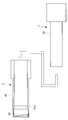
- FIGS. 1 and 2 An observation apparatus 1 according to a first embodiment of the present invention will be described below with reference to the drawings. As shown in FIGS. 1 and 2, the observation apparatus 1 according to the present embodiment observes cells S (see FIG. 10 and the like) floating in the culture solution (medium) W in the culture vessel 9. A camera unit 3, a tip unit 5 that is detachably attached to the tip of the camera unit 3, and an image analysis unit 7 that calculates the cell density in the culture medium W are provided.
- the culture vessel 9 is a bottomed cylindrical bioreactor whose upper surface is closed, and accommodates the cells S together with the culture medium W therein.
- the culture vessel 9 is covered with a cylindrical temperature adjustment jacket 11 that adjusts the temperature of the culture medium W.
- the culture vessel 9 is provided with a plurality of ports 9a for inserting various hoses 13 and probes 15 and an insertion port 9b for inserting the stirring mechanism 17 on the upper surface.
- ports 9 a are provided on the upper surface of the culture vessel 9. These ports 9a include a medium transport hose 13A for transporting the culture solution W, an air supply hose 13B for sending air to the culture solution W, a pH probe 15A for measuring the pH of the culture solution W, and the temperature of the culture solution W. A temperature measurement probe 15B for measuring the CO2 pressure and a CO2 pressure probe 15C for measuring the CO2 pressure of the culture medium W are inserted.
- the camera unit 3 can be inserted into the remaining one port 9a of the culture vessel 9 with the tip unit 5 attached.
- the stirring mechanism 17 includes a stirring shaft 17a inserted into the culture vessel 9 through the insertion port 9b of the culture vessel 9, and a plurality of stirring blades 17b provided on the stirring shaft 17a.
- a plurality of agitating blades 17b are arranged at intervals in the circumferential direction at three locations in the longitudinal direction of the agitating shaft 17a.
- the stirring mechanism 17 can stir the culture medium W by rotating the stirring shaft 17a and the stirring blade 17b around the longitudinal axis by a driving unit such as a motor (not shown). Then, the culture medium W is agitated by the agitating mechanism 17 to prevent the cells S from sticking to the inner surface of the culture vessel 9, and the cells S can be cultured while floating in the culture medium W.
- a driving unit such as a motor (not shown).
- the camera unit 3 has a light source 21, a light guide fiber 23 that guides illumination light emitted from the light source 21, and different viewpoints for the same cell S.
- a stereo optical system (stereo imaging optical system) 25 that forms two images with parallax viewed from each other, and an imaging device (stereo imaging optical system) that captures the two images formed by the stereo optical system 25, respectively.
- symbol K indicates a light emitting area.
- the light source 21 is disposed on the base end side of the housing 29.
- the light guide fiber 23 guides illumination light from the light source 21 to the tip of the housing 29.
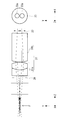
- the stereo optical system 25 includes, in order from the distal end side, an objective optical system 31 that condenses the light from the cell S, a diaphragm opening 33 that divides the light collected by the objective optical system 31, and a diaphragm opening 33.
- a deflection prism 35 that deflects the divided light and an imaging optical system 37 that forms an image of the light deflected by the deflection prism 35 are provided.
- the stereo optical system 25 has, for example, a magnification of 4 and an NA of 0.089.
- the stereo optical system 25 has an actual field of view of 1.06 mm in the X direction and 0.6 mm in the Y direction.
- the Y direction is stereo.
- the arrangement direction of the viewpoints of the stereo optical system 25 is referred to as a stereo direction.
- a direction along the optical axis of the stereo optical system 25 is defined as a Z direction
- a direction orthogonal to the optical axis of the stereo optical system 25 and orthogonal to the stereo direction is defined as an X direction.
- the objective optical system 31 includes a lens component 31a obtained by cementing a biconcave lens and a biconvex lens, and a convex / concave lens 31b.
- the objective optical system 31 has a diameter of 5.5 mm.
- the objective optical system 31 has a working distance (WD) of 4 mm, for example.
- reference numeral F indicates the position of the best focus surface
- reference numeral 39 indicates a cover glass. In FIG. 7, chief rays are mainly displayed.
- the diaphragm aperture 33 is arranged at the pupil position as shown in FIG.
- two holes 33a having a diameter of 1.4 mm are provided at an interval in the stereo direction.
- the deflection prism 35 is formed by bonding a prism 35 ⁇ / b> A and a prism 35 ⁇ / b> B having a plane whose surface on the image sensor 27 side is inclined in a direction in which the thickness increases as the absolute value in the Y direction increases. Is.
- the inclination of the surface on the image sensor 27 side has, for example, an angle of 2.9 ° in the + Y direction and an angle of ⁇ 2.9 ° in the ⁇ Y direction with respect to the optical axis.
- a light-shielding coating 35a that does not transmit light is applied between the prisms 35A and 35B.
- a light shielding member may be provided between the prism 35A and the prism 35B.
- the imaging optical system 37 is composed of a biconcave lens 37a and a lens component 37b obtained by cementing the convex / concave lens and the biconvex lens.
- the imaging optical system 37 has a diameter of 11 mm.
- between the deflection prism 35 and the imaging optical system 37 and between the imaging optical system 37 and the imaging device 27, light passing through the + Y direction and light passing through the ⁇ Y direction Each is provided with a light shielding member 36 for preventing the two from mixing.
- the image sensor 27 is arranged on the most proximal side of the housing 29.
- the imaging element 27 has an imaging area of 4.28 mm in the X direction and 5.9 mm in the Y direction.
- the cell image information acquired by the image sensor 27 is sent to the image analysis unit 7.
- the tip unit 5 irradiates the cell S with illumination light at an angle in a direction intersecting the stereo direction and a substantially rectangular tube-shaped protective cover 41 into which the camera unit 3 is inserted. And a mirror (polarized illumination unit) 43.
- the tip unit 5 has a protective cover 41 sterilized, and can be replaced as a disposable part that is disposable after each use.
- the protective cover 41 has an opening window 41a that opens on both side surfaces facing in the width direction on the base end side with respect to the front end. These opening windows 41 a are arranged between the mirror 43 and the objective optical system 31 in a state where the camera unit 3 is inserted into the protective cover 41.
- the opening window 41a has a size that allows the cells S and the culture medium W to pass through the inside of the protective cover 41 in the width direction.
- These opening windows 41a are formed, for example, by dividing the protective cover 41 into a distal end side and a proximal end side in the longitudinal direction and connecting the distal end side and the proximal end side at two locations in the circumferential direction of the protective cover 41. It may be an opening.
- the mirror 43 is disposed at the distal end of the protective cover 41 so as to face the proximal end side. Further, the mirror 43 has a reflection surface having an inclination of 6.5 ° with respect to the optical axis of the objective optical system 31. For example, the mirror 43 reflects the illumination light guided by the light guide fiber 23 toward the objective optical system 31 of the camera unit 3 at an angle in a direction orthogonal to the stereo direction, thereby culturing. The cells S in the liquid W are incidentally illuminated.
- the image analysis unit 7 specifies the position of the cell S included in each of the two images acquired by the image sensor 27. Then, the image analysis unit 7 calculates the cell density in the culture medium W based on the number of cells S present in the predetermined region.
- the predetermined area is, for example, an in-focus range and is set in advance. In the present embodiment, for example, the distance from the best focus position is preferably in the range of Z ⁇ 0.2 mm in the Z direction of the predetermined area.
- the operation of the observation apparatus 1 In order to observe the cells S cultured while being suspended in the culture medium W in the culture vessel 9 by the observation device 1 having the above-described configuration, first, as shown in FIG. In this state, the camera unit 3 and the tip unit 5 are inserted into the culture medium W through the port 9a of the culture vessel 9.
- illumination light is generated from the light source 21 of the camera unit 3, the illumination light is guided by the light guide fiber 23, and the illumination light is emitted from the tip of the light guide fiber 23 toward the mirror 43 of the tip unit 5.
- the illumination light reflected by the mirror 43 is irradiated to the cell S that has entered the tip unit 5 through the opening window 41a while floating in the culture medium W.
- the transmitted light of the illumination light transmitted through the cell S enters the stereo optical system 25 of the camera unit 3.
- the transmitted light of the illumination light transmitted through the cell S is collected by the objective optical system 31, and then divided by the aperture opening 33 and deflected by the deflecting prism 35, respectively. Thereby, two images with parallax viewed from different viewpoints for each cell S are formed on the plurality of cells S floating in the culture medium W. Then, the imaged two images are taken by the image sensor 27.
- the image information of the two images acquired by the image sensor 27 is sent to the image analysis unit 7. Then, based on the image information input by the image analysis unit 7, as shown in FIG. 10, a plurality of cells S are two-dimensional with parallax as viewed from different viewpoints for each individual cell S. Two images, that is, an upper image and a lower image shown in FIG. 10 are generated.
- the position of each cell S included in the generated two images of the plurality of cells S is specified by the image analysis unit 7.
- the cell density in the culture solution W is calculated by the image analysis unit 7 based on the number of cells S present in the predetermined region.
- the stereo optical system 25 forms two images with parallax viewed from different viewpoints for each cell S on the plurality of cells S in the culture medium W, thereby obtaining an image sensor.
- the position of the same cell S in the Y direction is shifted in the opposite direction between the images of these two images acquired by the unit 27 according to the distance from the stereo optical system 25.
- the difference between the Y coordinates of two cell images on the imaging surface obtained by photographing the same cell S on the best focus plane F is ⁇ Y0, and the imaging surface obtained by photographing the cell S at an arbitrary Z position
- the difference between the Y coordinates of two cell images is defined as ⁇ Y
- the size of each cell S is 20 ⁇ m
- the refractive index of the cell S is 1.36
- the refractive index of the culture medium W is 1.332
- the size of the display image is 0.48 mm ⁇
- the case of 0.48 mm (0.12 mm ⁇ 0.12 mm in object side conversion) is shown. The same applies to FIG.
- the image analysis unit 7 can accurately identify the cells S included in the predetermined region and the cells S not included.
- the cell density in the culture medium W can be calculated.
- the observation apparatus 1 which concerns on this embodiment, the cell density in the culture solution W can be measured accurately irrespective of the shape, size, etc. of the culture vessel 9 to be used.
- the unit of Z is mm.
- the culture vessel 9 that is a bioreactor is exemplified as the culture vessel for culturing the cells S.
- the culture vessel may be a cell culture pack in addition to the bioreactor.
- the camera unit 3 and the tip unit 5 of the observation apparatus 1 are inserted into the cell culture pack and used. The same applies to the second embodiment and the third embodiment.
- the observation apparatus 1 according to the present embodiment is different from the first embodiment in the configuration of the stereo optical system 25.
- portions having the same configuration as those of the observation apparatus 1 according to the first embodiment described above are denoted by the same reference numerals and description thereof is omitted.
- the stereo optical system 25 of the present embodiment does not include the deflecting prism 35, and includes an objective optical system 31 that condenses the light from the cell S, and a diaphragm opening 33 that divides the light collected by the objective optical system 31. And an imaging optical system 45 for separately imaging the lights divided by the aperture 33.
- the imaging optical system 45 includes a concave / convex lens 45a, a lens component 45b obtained by joining a biconcave lens and a biconvex lens, and a convex / concave lens 45c.
- the concave / convex lens 45a, the lens component 45b, and the convex / concave lens 45c are composed of a left and right lens pair.
- a light shielding member 36 is sandwiched between each pair of lenses.
- the lens pairs of the concavo-convex lens 45a, the lens component 45b, and the convex / concave lens 45c are arranged such that their optical axes are spaced apart from each other on the left and right, and can transmit the light divided by the aperture opening 33.
- the observation apparatus 1 according to this embodiment including the stereo optical system 25 having the above configuration also has the same effect as that of the first embodiment.
- the observation apparatus 1 according to the present embodiment is different from the first embodiment in the configuration of the stereo optical system 25.
- portions having the same configuration as those of the observation apparatus 1 according to the first embodiment described above are denoted by the same reference numerals and description thereof is omitted.
- the stereo optical system 25 of the present embodiment includes a tip prism (prism) 47A that divides the light from the cell S into two images.
- the stereo optical system 25 includes a diaphragm opening 48 having a single opening that is not divided into two, instead of the diaphragm opening 33.
- the stereo optical system 25 has, for example, a magnification of 4 and an NA of 0.087.
- the stereo optical system 25 has a real field of view of 1.07 mm in the X direction and 0.5 mm in the Y direction.
- reference numeral 49a indicates a lens component in which a convex / concave lens and a biconvex lens are cemented
- reference numeral 49b indicates a biconvex lens
- reference numeral 49c indicates a concave / convex lens
- reference numeral 49d indicates a concave / convex lens and a concave / convex lens.
- a cemented lens component is shown, and reference numeral 47B denotes a proximal prism.
- the front end prism 47A and the base end prism 47B have a certain thickness in the depth direction of the paper surface of FIG.
- the tip prism 47A has an incident surface with an inclination angle of ⁇ 2 ° and an output surface with an inclination angle of 7 °, and is symmetrical with respect to the optical axis on the + Y side and the ⁇ Y side. Yes.
- the chief ray incident angle to the aperture opening 48 has inclinations in opposite directions on the + Y side and the ⁇ Y side, and a stereo optical system is realized.
- the base prism 47B has an entrance surface and an exit surface formed in parallel to each other, the entrance surface has an inclination angle of 7 °, and the exit surface has an inclination angle of 7 °.
- the proximal prism 47B is composed of a proximal prism 47B1 and a proximal prism B2 that are line-symmetric with respect to the optical axis on the + Y side and the ⁇ Y side.
- the proximal prism 47B is configured to simultaneously photograph a stereo image by one image sensor (not shown) by bringing the + Y side image and the ⁇ Y side image close to each other. Without the base prism 47B, the image position on the + Y side and the image position on the -Y side are too far apart in the Y direction, resulting in a wasteful area unnecessary for density analysis near the middle, that is, near the optical axis. Therefore, it is necessary to use a wider imaging area of the imaging element.
- a light shielding member 36 is provided between the cemented lens component 49d and the imaging device (not shown) to prevent the + Y side light beam and the ⁇ Y side light beam from being mixed.
- the observation apparatus 1 according to this embodiment including the stereo optical system 25 having the above configuration also has the same effect as that of the first embodiment.
- An observation apparatus 51 according to the present embodiment is different from the first to third embodiments in that the light source 21 is disposed outside the camera unit 3, for example, as shown in FIG.
- portions having the same configuration as those of the observation apparatus 1 according to the first to third embodiments described above are denoted by the same reference numerals and description thereof is omitted.
- the stereo optical system 25 of the first embodiment described above will be exemplified and described.
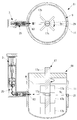
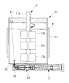
- the stirring shaft 17a is formed of a hollow cylindrical member.
- the camera unit 3 does not include the light source 21 and the light guide fiber 23, and is housed in the stirring shaft 17a without being attached to the tip unit 5.
- the stirring shaft 17a has a parallel plate-like observation window 53 made of an optically transparent material.
- the observation window 53 is disposed, for example, between the first stirring blade 17b and the second stirring blade 17b from the tip side of the stirring shaft 17a.
- the stereo optical system 25 is disposed along the longitudinal direction of the stirring shaft 17a, and forms an image of light from the cells S that passes through the observation window 53 and enters the stirring shaft 17a. Further, the stereo optical system 25 does not rotate around the stirring shaft 17a.
- a right-angle prism 55 that deflects light incident from the observation window 53 into the stirring shaft 17a in the longitudinal direction of the stirring shaft 17a.
- the light incident on the stirring shaft 17 a from the observation window 53 is incident on the stereo optical system 25 by the right-angle prism 55.
- the light source 21 is disposed outside the culture vessel 9 and emits illumination light from the outside of the culture vessel 9 toward the observation window 53.
- the light source 21 is arranged with a height shifted from the observation window 53. Thereby, the cells S can be illuminated obliquely, and an image with improved contrast of the cells S can be acquired.
- the culture vessel 9 has a parallel plate-shaped illumination window 9c on the side surface that transmits illumination light emitted from the light source 21. Thereby, the illumination light emitted from the light source 21 passes through the illumination window 9c and is irradiated to the cells S in the culture medium W. Then, the transmitted light of the illumination light that has passed through the cell S passes through the observation window 53, is then deflected by the right-angle prism 55, and is incident on the stereo optical system 25.
- an image of the cell S is taken when the observation window 53 overlaps the incident position of the stereo optical system 25 while the stirring shaft 17a is rotating.
- the configuration can be simplified.
- the stereo optical system 25 does not interfere with the flow of the culture medium W and the cells S.
- a 45 ° mirror may be employed instead of the right-angle prism 55.
- the stereo optical system 25 may rotate around the stirring shaft 17a together with the stirring shaft 17a. With this configuration, an image of the cell S is taken when the incident positions of the observation window 53 and the stereo optical system 25 face the light source 21 while the stirring shaft 17a is rotating. In this case, the stereo optical system 25 rotates together with the stirring shaft 17a, so that the imaging region can follow the flow of the culture medium W and the cells S.
- the light source 21 may generate illumination light from the entire area in the circumferential direction outside the culture vessel 9 toward the observation window 53.
- the stereo optical system 25 may rotate around the stirring shaft 17a together with the stirring shaft 17a.
- the illumination window 9c may be formed over the entire area of the culture vessel 9 in the circumferential direction.
- the observation device 61 according to the present embodiment is different from the fourth embodiment in that the camera unit 3 is disposed outside the culture vessel 9.
- portions having the same configuration as those of the observation device 51 according to the above-described fourth embodiment are denoted by the same reference numerals and description thereof is omitted.
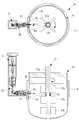
- the culture vessel 9 has a parallel plate-like observation window 63 made of an optically transparent material on the side surface.
- the stereo optical system 25 is disposed outside the culture vessel 9 and forms an image of light from the cell S that has passed through the observation window 63.
- a plurality of light sources 21 are attached to the stirring shaft 17a, and illumination light is emitted from each of the light sources 21 outward in the radial direction of the stirring shaft 17a.
- Each light source 21 is arranged so as to be shifted from the observation window 63 and the height.
- Each light source 21 is rotated around the stirring shaft 17a together with the stirring shaft 17a. Thereby, the illumination light emitted from each light source 21 is irradiated to the cell S in the culture solution W. Then, the transmitted light of the illumination light transmitted through the cell S passes through the observation window 63 and enters the stereo optical system 25.
- an image of the cell S is taken when any one of the light sources 21 faces the observation window 63 during the rotation of the stirring shaft 17a.
- the diameter of the stirring shaft 17a can be reduced by the amount that the stereo optical system 25 is not housed in the stirring shaft 17a, and the culture vessel 9 can be downsized.
- the stereo optical system 25 outside the culture vessel 9, the flow of the culture solution W and the cells S in the culture vessel 9 can be prevented from being disturbed by the stereo optical system 25. Moreover, the light from the cells S in the culture medium W irradiated with the illumination light passes through the parallel plate-like observation window 63 and enters the stereo optical system 25, so that the occurrence of aberration can be suppressed.
- a small light source such as an LED can be used as the light source 21. Further, by arranging the light source 21 so as to be shifted in height from the observation window 53, the cells S can be illuminated obliquely.
- the stirring shaft 17a may be hollow and the light source 21 may be housed in the stirring shaft 17a.
- the light source 21 may emit illumination light from the entire circumference in the circumferential direction of the stirring shaft 17a toward the outer side in the radial direction of the stirring shaft 17a while rotating around the stirring shaft 17a together with the stirring shaft 17a.
- the stirring shaft 17a may have an annular transmission window 65 made of an optically transparent material surrounding the light source 21.
- the transmission window 65 may have a comparative diffusion function that allows the transmitted illumination light to have various angle components.
- the illumination light emitted from the light source 21 and transmitted through the transmission window 65 of the stirring shaft 17a is applied to the cells S in the culture medium W. Then, the transmitted light of the illumination light transmitted through the cell S passes through the observation window 63 and enters the stereo optical system 25. In this case, while the light source 21 rotates together with the stirring shaft 17a, the illumination light is emitted from the entire circumference in the circumferential direction of the stirring shaft 17a toward the radially outward direction, so that one light source 21 can always shoot. .
- the light source 21 rotates with the stirring shaft 17a.
- the light source 21 does not rotate around the stirring shaft 17a and the observation window 63 is rotated. It is good also as emitting illumination light toward.
- the illumination light emitted from the light source 21 and transmitted through the transmission window 65 of the stirring shaft 17a is applied to the cells S in the culture medium W. Then, the transmitted light of the illumination light transmitted through the cell S passes through the observation window 63 and enters the stereo optical system 25. In this case, since the light source 21 is not rotated, the circuit connected to the light source 21 does not have to be complicated.
- the light source 21 may be arranged outside the culture vessel 9 and emit illumination light toward the observation window 63. Further, the light source 21 and the observation window 63 may be arranged to face each other in the radial direction of the stirring shaft 17a with the stirring shaft 17a interposed therebetween.
- the culture vessel 9 may have a parallel plate-shaped illumination window 9c that transmits the illumination light emitted from the light source 21. Furthermore, it is good also as forming the area
- the illumination light emitted from the light source 21 and transmitted through the illumination window 9c is transmitted through the light transmission member 17c of the stirring shaft 17a. Then, the illumination light is irradiated to the cells S in the culture medium W, and the transmitted light of the illumination light that has passed through the cells S passes through the observation window 63 and enters the stereo optical system 25.
- the light source 21 and the stereo optical system 25 are arranged outside the culture vessel 9 so that the light source 21 and the stereo optical system 25 do not interfere with the flow of the culture medium W and the cells S.
- the light source 21 may be arranged outside the culture vessel 9 and emit illumination light toward the stirring shaft 17a.
- the culture vessel 9 may have a parallel plate-like illumination window 9c that transmits illumination light emitted from the light source 21 on its side surface.
- the region arranged on the optical path of the illumination light of the stirring shaft 17 a may be formed by a reflection member 17 d made of a material that reflects the illumination light toward the observation window 63.
- the illumination light emitted from the light source 21 and transmitted through the illumination window 9c is reflected by the reflecting member 17d of the stirring shaft 17a. Then, the illumination light is irradiated to the cells S in the culture medium W, and the transmitted light of the illumination light that has passed through the cells S passes through the observation window 63 and enters the stereo optical system 25.
- the light source 21 and the stereo optical system 25 are arranged outside the culture vessel 9 so that the light source 21 and the stereo optical system 25 do not interfere with the flow of the culture medium W and the cells S.
- the light source 21 and the stereo optical system 25 can be disposed in the vicinity of the outside of the culture vessel 9, and space saving can be achieved.
- the light source 21, the illumination window 9c, and the observation window 63 are arranged opposite to each other with their positions shifted in the radial direction of the stirring shaft 17a. It is good. Further, the illumination light emitted from the light source 21 may pass through a position shifted in the longitudinal direction of the stirring shaft 17a with respect to the stirring blade 17b and enter the observation window 63.
- the illumination light emitted from the light source 21 and transmitted through the illumination window 9c is irradiated to the cells S in the culture medium W without being blocked by the stirring shaft 17a and the stirring blade 17b. Then, the transmitted light of the illumination light transmitted through the cell S passes through the observation window 63 and enters the stereo optical system 25. Therefore, except for the observation window 63 and the illumination window 9c, a simple configuration can be achieved as in the conventional culture vessel.
- the illumination light emitted from the light source 21 passes through a position shifted in the longitudinal direction of the stirring shaft 17a with respect to the stirring blade 17b.
- FIG. 5 at least a part of the stirring blade 17b is formed of an optically transparent material, and the illumination light emitted from the light source 21 passes through the region formed of the optically transparent material of the stirring blade 17b. It is good to do.
- the illumination light emitted from the light source 21 and transmitted through the illumination window 9c passes through the region formed of the optically transparent material of the stirring blade 17b. Then, the illumination light is irradiated to the cells S in the culture medium W, and the transmitted light of the illumination light that has passed through the cells S passes through the observation window 63 and enters the stereo optical system 25. Therefore, the cell density in a region corresponding to the depth where the stirring blade 17b is disposed in the culture vessel 9 can also be measured.
- the light source 21 may emit illumination light toward the stirring blade 17b.
- the region arranged on the optical path of the illumination light of the stirring blade 17b may be formed of a material that reflects the illumination light toward the observation window 63.
- the illumination light emitted from the light source 21 and transmitted through the illumination window 9c is reflected by the stirring blade 17b. Then, the illumination light is irradiated to the cells S in the culture medium W, and the transmitted light of the illumination light that has passed through the cells S passes through the observation window 63 and enters the stereo optical system 25.
- the light source 21 and the stereo optical system 25 are arranged outside the culture vessel 9 so that the light source 21 and the stereo optical system 25 do not interfere with the flow of the culture medium W and the cells S.
- the light source 21 and the stereo optical system 25 can be disposed in the vicinity of the outside of the culture vessel 9, and space saving can be achieved.
- the light source 21 may be disposed outside the culture vessel 9 and emit illumination light into the culture vessel 9.
- the culture vessel 9 deflects the illumination light emitted from the light source 21 in the direction along the inner peripheral surface in the culture vessel 9, and the deflection in the culture solution W after being deflected by the first prism 57. It is good also as having the 2nd prism 59 which deflects the transmitted light of the illumination light irradiated to the cell S toward the outer side of the culture container 9, respectively.
- the stereo optical system 25 may be disposed outside the culture vessel 9 and may form an image of the light emitted to the outside of the culture vessel 9 by the second prism 59.
- the flow of the culture solution W and the cells S in the culture vessel 9 is not disturbed by the stereo optical system 25.
- the second prism 59 by deflecting the light from the cells S by the second prism 59, the light of the cells S emitted from the direction intersecting the optical axis of the stereo optical system 25 can be incident on the stereo optical system 25.
- the illumination light does not cross inside the culture vessel 9, and the distance between the first prism 57 and the second prism 59 can be shortened.
- the volume of the culture solution W in the optical path of the illumination light is small and the number of cells S is small, it is possible to suppress the influence of the scattering of the illumination light and obtain an image with high contrast.
- the culture vessel 9 may have an observation window 63 on the bottom surface.
- the light source 21 may be disposed on the upper surface of the culture vessel 9 and emit illumination light toward the observation window 63.
- the stereo optical system 25 may be disposed below the bottom surface of the culture vessel 9 and may form an image of light from the cells S that has passed through the observation window 63 and exited from the culture vessel 9.
- the stereo optical system 25 may be arranged along the bottom surface of the culture vessel 9. Further, between the observation window 63 and the stereo optical system 25, a right-angle prism 55 that makes the light transmitted through the observation window 63 incident on the stereo optical system 25 by deflecting the light that passes through the bottom surface of the culture vessel 9 is disposed. It is good as well.
- the height position of the observation window 63 of the stereo optical system 25 and the height position of the light source 21 are different from each other. Since oblique illumination images can be acquired by illuminating light incident obliquely with respect to the optical axis, the light source 21 may be shifted from the optical axis of the stereo optical system 25.
- the stereo optical system 25 may be arranged to be inclined with respect to the optical axis of the illumination light emitted from the light source 21.
Landscapes
- Engineering & Computer Science (AREA)
- Chemical & Material Sciences (AREA)
- Health & Medical Sciences (AREA)
- Physics & Mathematics (AREA)
- Life Sciences & Earth Sciences (AREA)
- General Physics & Mathematics (AREA)
- General Health & Medical Sciences (AREA)
- Analytical Chemistry (AREA)
- Computer Vision & Pattern Recognition (AREA)
- Bioinformatics & Cheminformatics (AREA)
- Biochemistry (AREA)
- Multimedia (AREA)
- Wood Science & Technology (AREA)
- Zoology (AREA)
- Organic Chemistry (AREA)
- Dispersion Chemistry (AREA)
- Immunology (AREA)
- Biotechnology (AREA)
- Pathology (AREA)
- Biomedical Technology (AREA)
- Optics & Photonics (AREA)
- Theoretical Computer Science (AREA)
- Sustainable Development (AREA)
- Microbiology (AREA)
- Genetics & Genomics (AREA)
- General Engineering & Computer Science (AREA)
- Medical Informatics (AREA)
- Nuclear Medicine, Radiotherapy & Molecular Imaging (AREA)
- Radiology & Medical Imaging (AREA)
- Quality & Reliability (AREA)
- Virology (AREA)
- Cell Biology (AREA)
- Medicinal Chemistry (AREA)
- Signal Processing (AREA)
- Apparatus Associated With Microorganisms And Enzymes (AREA)
- Microscoopes, Condenser (AREA)
Abstract
La présente invention concerne un dispositif d'observation qui comprend : un système optique stéréo (25) qui forme deux images de cellules en suspension dans un milieu de culture liquide dans un récipient de culture, lesdites deux images étant acquises en observant les mêmes cellules à partir de points de vue différents et présentant une disparité ; un élément de capture d'images (27) qui capture les deux images individuelles formées par le système optique stéréo (25) ; et une unité d'analyse d'images qui spécifie les positions de cellules dans les deux images individuelles capturées par l'élément de capture d'images (27) et calcule la densité cellulaire dans le milieu de culture liquide en fonction du nombre de cellules présentes dans une zone définie.
Priority Applications (4)
| Application Number | Priority Date | Filing Date | Title |
|---|---|---|---|
| PCT/JP2018/022027 WO2019234916A1 (fr) | 2018-06-08 | 2018-06-08 | Dispositif d'observation |
| PCT/JP2019/022520 WO2019235563A1 (fr) | 2018-06-08 | 2019-06-06 | Appareil d'observation |
| JP2020523169A JP7064584B2 (ja) | 2018-06-08 | 2019-06-06 | 観察装置および細胞観察方法 |
| US17/101,581 US11635364B2 (en) | 2018-06-08 | 2020-11-23 | Observation device |
Applications Claiming Priority (1)
| Application Number | Priority Date | Filing Date | Title |
|---|---|---|---|
| PCT/JP2018/022027 WO2019234916A1 (fr) | 2018-06-08 | 2018-06-08 | Dispositif d'observation |
Publications (1)
| Publication Number | Publication Date |
|---|---|
| WO2019234916A1 true WO2019234916A1 (fr) | 2019-12-12 |
Family
ID=68769806
Family Applications (2)
| Application Number | Title | Priority Date | Filing Date |
|---|---|---|---|
| PCT/JP2018/022027 Ceased WO2019234916A1 (fr) | 2018-06-08 | 2018-06-08 | Dispositif d'observation |
| PCT/JP2019/022520 Ceased WO2019235563A1 (fr) | 2018-06-08 | 2019-06-06 | Appareil d'observation |
Family Applications After (1)
| Application Number | Title | Priority Date | Filing Date |
|---|---|---|---|
| PCT/JP2019/022520 Ceased WO2019235563A1 (fr) | 2018-06-08 | 2019-06-06 | Appareil d'observation |
Country Status (3)
| Country | Link |
|---|---|
| US (1) | US11635364B2 (fr) |
| JP (1) | JP7064584B2 (fr) |
| WO (2) | WO2019234916A1 (fr) |
Cited By (2)
| Publication number | Priority date | Publication date | Assignee | Title |
|---|---|---|---|---|
| US11299701B2 (en) | 2019-03-19 | 2022-04-12 | Olympus Corporation | Culture-medium-monitoring apparatus |
| US11635364B2 (en) | 2018-06-08 | 2023-04-25 | Evident Corporation | Observation device |
Families Citing this family (1)
| Publication number | Priority date | Publication date | Assignee | Title |
|---|---|---|---|---|
| CN116622470A (zh) * | 2023-05-16 | 2023-08-22 | 河海大学 | 一种微藻培养用硅胶质搅拌桨及微藻培养方法 |
Citations (7)
| Publication number | Priority date | Publication date | Assignee | Title |
|---|---|---|---|---|
| JP2004512845A (ja) * | 2000-10-24 | 2004-04-30 | オンコシス リミテッド ライアビリティ カンパニー | 三次元の検体内の細胞を選択的に標的化する方法およびデバイス |
| JP2005241791A (ja) * | 2004-02-25 | 2005-09-08 | Olympus Corp | ステレオ撮像装置 |
| JP2010128354A (ja) * | 2008-11-28 | 2010-06-10 | Olympus Medical Systems Corp | ステレオ光学系、並びにそれを用いたステレオ計測用光学装置、ステレオ計測装置及びステレオ観察装置 |
| JP2011247965A (ja) * | 2010-05-24 | 2011-12-08 | Olympus Imaging Corp | ステレオ撮影対応型の交換レンズ、撮像装置本体、および撮像装置 |
| JP2017140006A (ja) * | 2016-02-12 | 2017-08-17 | 大日本印刷株式会社 | 培養状態解析システム及び培養状態解析方法、並びに、プログラム |
| WO2017217148A1 (fr) * | 2016-06-13 | 2017-12-21 | ソニー株式会社 | Dispositif, dispositif de traitement d'informations, programme, et procédé de traitement d'informations |
| WO2017217180A1 (fr) * | 2016-06-15 | 2017-12-21 | ソニー株式会社 | Dispositif de traitement d'informations, système d'observation, procédé d'observation et programme |
Family Cites Families (22)
| Publication number | Priority date | Publication date | Assignee | Title |
|---|---|---|---|---|
| US6608682B2 (en) * | 1999-01-25 | 2003-08-19 | Amnis Corporation | Imaging and analyzing parameters of small moving objects such as cells |
| US7217321B2 (en) * | 2001-04-06 | 2007-05-15 | California Institute Of Technology | Microfluidic protein crystallography techniques |
| WO2007067999A2 (fr) * | 2005-12-09 | 2007-06-14 | Amnis Corporation | Systeme d'imagerie a profondeur de champ etendue pour analyse d'objets a grande vitesse |
| KR101773601B1 (ko) * | 2009-03-09 | 2017-08-31 | 도요세이칸 그룹 홀딩스 가부시키가이샤 | 세포 배양 방법, 세포 배양 장치, 용기 내의 계수 대상물의 계수 방법, 및 계수용 장치 |
| JP5659158B2 (ja) | 2009-07-21 | 2015-01-28 | 国立大学法人京都大学 | 画像処理装置、培養観察装置、及び画像処理方法 |
| JP5797911B2 (ja) | 2011-02-18 | 2015-10-21 | 日本光電工業株式会社 | 溶液のpH計測方法及び溶液のpH計測装置 |
| JP2013088898A (ja) * | 2011-10-14 | 2013-05-13 | Sony Corp | 3dデータ解析のための装置、方法及びプログラムと、微小粒子解析システム |
| JP5896702B2 (ja) | 2011-11-30 | 2016-03-30 | オリンパス株式会社 | 光音響顕微鏡 |
| JP6086719B2 (ja) | 2012-12-25 | 2017-03-01 | オリンパス株式会社 | 光音響顕微鏡 |
| JP6112861B2 (ja) | 2012-12-28 | 2017-04-12 | キヤノン株式会社 | 被検体情報取得装置、信号処理装置および表示装置 |
| JP6049209B2 (ja) | 2014-01-28 | 2016-12-21 | 富士フイルム株式会社 | 光音響計測用プローブおよびそれを備えた光音響計測装置 |
| WO2016084217A1 (fr) | 2014-11-28 | 2016-06-02 | オリンパス株式会社 | Microscope photo-acoustique et procédé de détection de signaux photo-acoustiques |
| JP6402677B2 (ja) | 2015-04-23 | 2018-10-10 | 横河電機株式会社 | 光音響波検出装置、光音響イメージング装置 |
| JP6664909B2 (ja) * | 2015-09-01 | 2020-03-13 | レボックス株式会社 | 撮像光学装置 |
| JP2017140007A (ja) | 2016-02-12 | 2017-08-17 | 株式会社ニコン | 浮遊培養装置および大量培養システム |
| CN110099995A (zh) * | 2017-01-06 | 2019-08-06 | 奥林巴斯株式会社 | 细胞观察系统 |
| JP6330070B1 (ja) * | 2017-02-21 | 2018-05-23 | オリンパス株式会社 | 観察装置、観察システム及び観察装置の制御方法 |
| JP6999129B2 (ja) | 2017-09-06 | 2022-01-18 | 浜松ホトニクス株式会社 | 細胞観察システムおよび細胞観察方法 |
| JP7144958B2 (ja) | 2018-03-30 | 2022-09-30 | 株式会社エビデント | 観察装置および観察システム |
| WO2019234916A1 (fr) | 2018-06-08 | 2019-12-12 | オリンパス株式会社 | Dispositif d'observation |
| JP7194030B2 (ja) | 2019-01-30 | 2022-12-21 | 株式会社エビデント | 赤血球モニタリング装置 |
| JP2020174574A (ja) | 2019-04-18 | 2020-10-29 | オリンパス株式会社 | 培地交換システムおよび培地交換方法 |
-
2018
- 2018-06-08 WO PCT/JP2018/022027 patent/WO2019234916A1/fr not_active Ceased
-
2019
- 2019-06-06 WO PCT/JP2019/022520 patent/WO2019235563A1/fr not_active Ceased
- 2019-06-06 JP JP2020523169A patent/JP7064584B2/ja active Active
-
2020
- 2020-11-23 US US17/101,581 patent/US11635364B2/en active Active
Patent Citations (7)
| Publication number | Priority date | Publication date | Assignee | Title |
|---|---|---|---|---|
| JP2004512845A (ja) * | 2000-10-24 | 2004-04-30 | オンコシス リミテッド ライアビリティ カンパニー | 三次元の検体内の細胞を選択的に標的化する方法およびデバイス |
| JP2005241791A (ja) * | 2004-02-25 | 2005-09-08 | Olympus Corp | ステレオ撮像装置 |
| JP2010128354A (ja) * | 2008-11-28 | 2010-06-10 | Olympus Medical Systems Corp | ステレオ光学系、並びにそれを用いたステレオ計測用光学装置、ステレオ計測装置及びステレオ観察装置 |
| JP2011247965A (ja) * | 2010-05-24 | 2011-12-08 | Olympus Imaging Corp | ステレオ撮影対応型の交換レンズ、撮像装置本体、および撮像装置 |
| JP2017140006A (ja) * | 2016-02-12 | 2017-08-17 | 大日本印刷株式会社 | 培養状態解析システム及び培養状態解析方法、並びに、プログラム |
| WO2017217148A1 (fr) * | 2016-06-13 | 2017-12-21 | ソニー株式会社 | Dispositif, dispositif de traitement d'informations, programme, et procédé de traitement d'informations |
| WO2017217180A1 (fr) * | 2016-06-15 | 2017-12-21 | ソニー株式会社 | Dispositif de traitement d'informations, système d'observation, procédé d'observation et programme |
Cited By (2)
| Publication number | Priority date | Publication date | Assignee | Title |
|---|---|---|---|---|
| US11635364B2 (en) | 2018-06-08 | 2023-04-25 | Evident Corporation | Observation device |
| US11299701B2 (en) | 2019-03-19 | 2022-04-12 | Olympus Corporation | Culture-medium-monitoring apparatus |
Also Published As
| Publication number | Publication date |
|---|---|
| US11635364B2 (en) | 2023-04-25 |
| WO2019235563A1 (fr) | 2019-12-12 |
| JP7064584B2 (ja) | 2022-05-10 |
| JPWO2019235563A1 (ja) | 2021-06-17 |
| US20210102887A1 (en) | 2021-04-08 |
Similar Documents
| Publication | Publication Date | Title |
|---|---|---|
| EP3918402B1 (fr) | Étalonnage d'un système d'imagerie à champ lumineux | |
| US9435734B2 (en) | Method for observing stem cells, method for removal of cell region in state tending toward differentiation, and device for observing stem cells | |
| US11635364B2 (en) | Observation device | |
| JP5556444B2 (ja) | 顕微鏡、培養観察装置 | |
| CA2978787C (fr) | Procede et appareil de microscopie | |
| US20200379231A1 (en) | Observation apparatus | |
| JP4731847B2 (ja) | ペトリディッシュ、チャンバー装置、光学顕微鏡観察方法及び試料分析方法 | |
| US11299701B2 (en) | Culture-medium-monitoring apparatus | |
| US11188736B2 (en) | Observation device | |
| JP2012147739A (ja) | 観察装置 | |
| CN105765438A (zh) | 用于使样本成像的光学布置 | |
| JP2018032009A (ja) | 顕微鏡 | |
| JPWO2019176048A1 (ja) | 細胞画像処理装置 | |
| JP2009145102A (ja) | エバネッセント波発生装置及びそれを用いた観察装置 | |
| JP6602855B2 (ja) | ミラーデバイス | |
| WO2021117211A1 (fr) | Dispositif de culture cellulaire | |
| JP6980898B2 (ja) | 細胞画像処理装置 | |
| US20060193496A1 (en) | Examination method and examination-assisting tool | |
| US20260126636A1 (en) | Objective lens unit for a microscope, microscope comprising the objective lens unit, and method of setting the object plane of a microscope | |
| EP4737976A1 (fr) | Unité de lentille d'objectif pour un microscope, microscope comprenant l'unité de lentille d'objectif et procédé de réglage du plan d'objet d'un microscope | |
| US20250093634A1 (en) | Imaging apparatus | |
| JP2020167959A (ja) | 培地モニタリング装置 | |
| JP7037636B2 (ja) | 観察装置 | |
| US20260126638A1 (en) | Objective lens unit for a microscope, microscope comprising the objective lens unit, and methods of performing cytometry | |
| Inutsuka et al. | Single-shot label-free nanoscopy for quantitative organelle visualization on standard commercial microscopes |
Legal Events
| Date | Code | Title | Description |
|---|---|---|---|
| 121 | Ep: the epo has been informed by wipo that ep was designated in this application |
Ref document number: 18921384 Country of ref document: EP Kind code of ref document: A1 |
|
| NENP | Non-entry into the national phase |
Ref country code: DE |
|
| 122 | Ep: pct application non-entry in european phase |
Ref document number: 18921384 Country of ref document: EP Kind code of ref document: A1 |
|
| NENP | Non-entry into the national phase |
Ref country code: JP |