WO2019235012A1 - Machine à laver - Google Patents
Machine à laver Download PDFInfo
- Publication number
- WO2019235012A1 WO2019235012A1 PCT/JP2019/009442 JP2019009442W WO2019235012A1 WO 2019235012 A1 WO2019235012 A1 WO 2019235012A1 JP 2019009442 W JP2019009442 W JP 2019009442W WO 2019235012 A1 WO2019235012 A1 WO 2019235012A1
- Authority
- WO
- WIPO (PCT)
- Prior art keywords
- elastic member
- water tank
- drum
- washing machine
- end portion
- Prior art date
- Legal status (The legal status is an assumption and is not a legal conclusion. Google has not performed a legal analysis and makes no representation as to the accuracy of the status listed.)
- Ceased
Links
Images


Classifications
-
- D—TEXTILES; PAPER
- D06—TREATMENT OF TEXTILES OR THE LIKE; LAUNDERING; FLEXIBLE MATERIALS NOT OTHERWISE PROVIDED FOR
- D06F—LAUNDERING, DRYING, IRONING, PRESSING OR FOLDING TEXTILE ARTICLES
- D06F37/00—Details specific to washing machines covered by groups D06F21/00 - D06F25/00
- D06F37/20—Mountings, e.g. resilient mountings, for the rotary receptacle, motor, tub or casing; Preventing or damping vibrations
- D06F37/22—Mountings, e.g. resilient mountings, for the rotary receptacle, motor, tub or casing; Preventing or damping vibrations in machines with a receptacle rotating or oscillating about a horizontal axis
Definitions
- the present invention relates to a washing machine.
- the washing machine described in Patent Document 1 includes a rotating drum, a water tank, an outer box, and a coil spring.
- the rotating drum rotates around the rotation axis.
- the aquarium covers the rotating drum.
- the outer box contains a water tank and a rotating drum.
- the coil spring is connected to the front lower part of the water tank and a member arranged inside the front surface of the outer box.
- the rotating drum (washing tub) rotates during the dehydrating operation
- the laundry sticks to the inner peripheral surface of the rotating drum and rotates together with the rotating drum.
- the load becomes an eccentric load and swings in the rotating direction of the rotating drum.
- the laundry in the rotary drum rotates upward together with the rotary drum.
- the rotating drum swings upward.
- the laundry in the rotating drum rotates downward together with the rotating drum. Accordingly, in the lower rotation region of the rotary drum, the rotary drum swings downward, so that the water tank receives pressure downward through the rotary drum. As a result, the portion of the water tank that covers the lower rotation region sinks more than the portion that covers the upper rotation region.
- the coil spring is located at the center of the lower part of the water tank. Therefore, during the dehydration operation, the portion of the water tank that covers the upper rotation region may sink more than the portion that covers the lower rotation region. As a result, the posture of the water tank may become unbalanced during the dehydration operation.
- An object of the present invention is to provide a washing machine that can stably support a water tank during dehydration operation.
- the washing machine includes a washing tub, a water tub, a housing, and an elastic member.
- the washing tub is supported so as to be rotatable about a rotation axis.
- the water tub accommodates the washing tub.
- the housing accommodates the water tank.
- the elastic member is attached to the casing and attached to the lower part of the water tank. At the position in the width direction of the casing, the position of the elastic member is different from the position of the rotating shaft.
- the water tank can be stably supported during the dehydration operation.
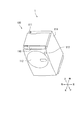
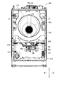
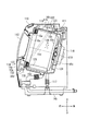
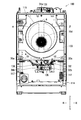
- FIG. 1 It is a perspective view of the washing machine of this embodiment. It is sectional drawing of a washing machine. It is a front view of a washing machine. It is an enlarged view of a 2nd elastic member. It is sectional drawing which shows the 1st modification of a washing machine. It is a front view which shows the 2nd modification of a washing machine.
- FIG. 1 is a perspective view of the washing machine 100.
- the washing machine 100 includes an operation display unit 110, a connection port 111, a door 112, a door opening button 113, and a housing 114.
- the front / rear / left / right direction and the up / down direction are defined with the user's position relative to the washing machine 100 when the user operates the operation display unit 110 in a normal posture as the front.
- the operation display unit 110 receives an instruction for the washing machine 100.
- the operation display unit 110 includes, for example, operation keys.
- the operation display unit 110 is provided in the upper part of the front surface of the housing 114.
- the connection port 111 is provided in the upper part of the front surface of the housing 114.
- the connection port 111 is connected to a faucet. Water discharged from the faucet is supplied to the washing machine 100 through the connection port 111.
- the door 112 is provided on the front surface of the housing 114.
- the door 112 partitions the inside of the housing 114 from the outside of the housing 114.
- the door opening button 113 is disposed around the door 112. The door 112 is opened by operating the door opening button 113.
- FIG. 2 is a cross-sectional view of the washing machine 100.
- the washing machine 100 further includes a drum 115, a water tank 116, and a damper 117.
- the drum 115 is an example of the washing tub of the present invention.
- the drum 115 is disposed inside the housing 114.
- the drum 115 can store laundry.
- the drum 115 has a hollow shape.
- the drum 115 has a drum opening 15a, a drum side 15b, and a drum bottom 15c.
- the drum bottom portion 15c has a substantially cylindrical shape with both front and rear ends opened.
- the drum bottom 15c is provided at the rear of the drum side 15b and closes the rear of the drum side 15b.
- the drum opening 15a is provided in the front part of the drum side part 15b.
- the drum opening 15 a communicates the inside of the drum 115 with the outside of the drum 115.
- the interior of the drum 115 indicates a space surrounded by the drum side portion 15b and the drum bottom portion 15c.
- the laundry can be put into the drum 115 through the drum opening 15a.
- the drum 115 further has a rotating shaft 15d.
- the rotation shaft 15d is an axis that passes through the center of the drum opening 15a and the center of the drum bottom 15c.
- the rotating shaft 15d is inclined at an acute angle ⁇ with respect to the front-rear direction. Further, the rotation shaft 15d may be parallel to the front-rear direction.
- the water tank 116 has a hollow shape.
- the water tank 116 accommodates the drum 115.
- the water tank 116 is disposed inside the housing 114.
- Water tank 116 has water tank opening 16a, water tank side part 16b, and water tank bottom 16c.
- the water tank side portion 16b has a substantially cylindrical shape with both front and rear ends opened.
- a drum side portion 15b is disposed inside the water tank side portion 16b.
- the water tank bottom part 16c is provided at the rear part of the water tank side part 16b and closes the rear part of the water tank side part 16b.
- the water tank bottom 16c faces the drum bottom 15c from the rear.
- the water tank opening 16a is provided in the front part of the water tank side part 16b.
- the water tank opening 16 a communicates the inside of the water tank 116 with the outside of the water tank 116.
- the water tank opening 16a faces the drum opening 15a from the front. Further, the water tank opening 16a faces the door 112 in a closed state.
- the inside of the water tank 116 indicates a space surrounded by the water tank side part 16b and the water tank bottom part 16c.
- a drum 115 is disposed inside the water tank 116.
- the drum opening 15a and the water tank opening 16a face the outside of the housing 114.
- the user can put the laundry into the drum 115 through the drum opening 15a and the water tank opening 16a.
- the damper 117 is interposed between the lower part 16 d of the water tank 116 and the bottom part 14 b of the housing 114.
- the damper 117 attenuates the vibration of the water tank 116.
- the damper 117 supports the lower part 16 d of the water tank 116.
- the damper 117 supports the rear part of the water tank 116.
- a pair of dampers 117 is provided.
- a pair of dampers 117 are arranged at intervals in the left-right direction.
- a pair of dampers 117 supports the left and right sides of the water tank 116.
- Washing machine 100 further includes a drum motor 118, an output shaft 119, a plurality of holes 120, and a plurality of baffles 121.
- the drum motor 118 rotates the drum 115.
- the drum motor 118 is connected to the drum 115 via the output shaft 119.
- the output shaft 119 supports the drum 115 rotatably.
- the plurality of holes 120 are formed in the drum 115.
- the plurality of holes 120 penetrate the drum 115.
- Each of the plurality of baffles 121 is formed on the inner peripheral surface of the drum 115.
- Each of the plurality of baffles 121 protrudes inside the drum 115.
- the plurality of baffles 121 are arranged along the circumferential direction of the drum 115.
- the laundry is put into the drum 115.
- water is supplied into the drum 115 through the plurality of holes 120, and the laundry is immersed in the water.
- the drum 115 is rotated by the power of the drum motor 118.
- the drum 115 rotates, the laundry is lifted by the baffle 121.
- the laundry falls by gravity and is struck against the inner peripheral surface of the drum 115.
- the drum 115 continues to rotate, the operation of lifting the laundry and the operation of hitting the laundry against the inner peripheral surface of the drum 115 are alternately repeated. As a result, the laundry is washed.
- the washing machine 100 further includes a fan 122, a heater 123, and a duct 124.
- the fan 122 is connected to the drum 115 via the heater 123 and the duct 124.
- warm air generated by the fan 122 and the heater 123 is supplied into the water tank 116 through the duct 124.
- the warm air supplied to the inside of the water tank 116 is supplied to the inside of the drum 115 through the plurality of holes 120. As a result, the laundry inside the drum 115 is dried.
- the washing machine 100 is configured to wash laundry by performing a washing operation, a rinsing operation, a dehydration operation, and a drying operation, for example.
- the washing operation indicates washing the laundry.
- Rinse operation indicates rinsing the laundry.
- the dehydration operation indicates that the laundry is dehydrated.
- the drying operation indicates that the laundry is dried. Note that the washing machine 100 may not have a drying function.
- FIG. 3 is a front view of the washing machine 100.
- the door 112 and the front portion 14a (see FIG. 2) of the housing 114 are omitted.
- the rotation direction A indicates the direction in which the drum 115 rotates around the rotation shaft 15d when the washing machine 100 performs the dehydration operation.
- the rotation direction A indicates the clockwise direction in FIG.
- the drum 115 has an upper rotation area ⁇ and a lower rotation area ⁇ .
- the upper rotation area ⁇ indicates an area of the drum 115 in which the rotation direction A of the drum 115 is directed upward.
- the upper rotation region ⁇ indicates a region on the right side of the rotation shaft 15 d in the drum 115.
- the lower rotation area ⁇ indicates an area of the drum 115 in which the rotation direction A of the drum 115 is directed downward.
- the lower rotation region ⁇ indicates a region on the left side of the rotation shaft 15 d in the drum 115.
- the drum 115 rotates in a certain direction around the rotation shaft 15d.
- the drum 115 rotates at a higher speed during the dehydrating operation than during the washing operation.
- the drum 115 rotates in the rotation direction A (see FIG. 3) during the dehydration operation.
- the drum 115 rotates so that the portion of the drum 115 to which the laundry is attached swings in the rotation direction A side.
- the drum 115 swings downward in the lower rotation region ⁇ , so that a portion of the water tank 116 covering the lower rotation region ⁇ receives pressure downward via the drum 115.
- the drum 115 swings upward.
- the problem of uneven subsidence of the water tank 116 is likely to occur during the dehydration operation.
- the washing machine 100 further includes a first elastic member 131, a second elastic member 132, a first interposing member 133, and a third interposing member 135.
- the first elastic member 131 is an elastically deformable member.
- the first elastic member 131 is, for example, a coil spring.
- the first elastic member 131 is attached to the casing 114 and attached to the upper part of the water tank 116.
- the first elastic member 131 has an upper end portion 31a and a lower end portion 31b.
- the upper end portion 31a indicates a portion of the first elastic member 131 that is attached to the housing 114.
- the lower end portion 31 b indicates a portion of the first elastic member 131 that is attached to the water tank 116.
- the first elastic member 131 has a shape extending from the upper end portion 31a toward the lower end portion 31b.
- the upper end portion 31a is located above the lower end portion 31b.
- the first elastic member 131 is elastically deformed in a direction in which the upper end portion 31a and the lower end portion 31b approach and separate from each other.
- the first elastic member 131 is attached to the housing 114 not only when the first elastic member 131 is directly attached to the housing 114 but also when attached indirectly via a member such as a bracket. included.
- the first elastic member 131 is attached to the upper part of the water tank 116 not only when the first elastic member 131 is directly attached to the upper part of the water tank 116 but also indirectly through a member such as a bracket. Cases are also included.
- the first elastic member 131 is located above the rotation shaft 15d. At the position in the left-right direction, the position of the first elastic member 131 is the same as the position of the rotation shaft 15d.
- the restoring force of the first elastic member 131 is generated in the direction in which the first elastic member 131 contracts. At this time, the restoring force of the first elastic member 131 is generated in the direction Y1 in which the lower end 31b approaches the upper end 31a.
- the restoring force of the first elastic member 131 When the restoring force of the first elastic member 131 is generated, the restoring force of the first elastic member 131 acts on the water tank 116 so that the upper part of the water tank 116 is lifted. As a result, the first elastic member 131 supports the upper part of the water tank 116.
- FIG. 4 is an enlarged view of the second elastic member 132.
- the attachment structure of the second elastic member 132 will be described with reference to FIGS.
- the second elastic member 132 is attached to the housing 114 and attached to the lower portion 16d of the water tank 116.
- the second elastic member 132 is attached to the housing 114 not only when the second elastic member 132 is directly attached to the housing 114 but also when attached indirectly via a member such as a bracket. included. Further, the second elastic member 132 is attached to the lower portion 16d of the water tank 116 not only when the second elastic member 132 is directly attached to the lower portion 16d of the water tank 116 but also indirectly through a member such as a bracket. The case where it is attached is also included.
- the second elastic member 132 is indirectly attached to the housing 114 via the first interposed member 133. Further, the second elastic member 132 is indirectly attached to the lower portion 16 d of the water tank 116 via the third interposed member 135.
- the first interposed member 133 is fixed to the housing 114.
- the 1st interposition member 133 is formed with a sheet metal or resin, for example.
- the first interposed member 133 is disposed between the water tank 116 and the front portion 14 a of the housing 114.
- the first interposed member 133 supports the front portion of the water tank 116 via the second elastic member 132.
- the third interposed member 135 is fixed to the lower portion 16d of the water tank 116.
- the third interposed member 135 is made of, for example, sheet metal or resin.
- the third interposed member 135 may be a member integrated with the water tank 116 or may be a separate member. In the present embodiment, the third interposed member 135 protrudes to the left from the water tank 116 and is fixed to a position located on the left side of the lower part 16 d of the water tank 116.
- the second elastic member 132 will be described in detail.
- the second elastic member 132 is an example of the elastic member of the present invention.
- the second elastic member 132 is an elastically deformable member.
- the second elastic member 132 is, for example, a coil spring.
- the second elastic member 132 has a first end portion 32a and a second end portion 32b.
- the second elastic member 132 has a shape extending from the first end portion 32a toward the second end portion 32b.
- the first end portion 32a indicates a portion of the second elastic member 132 that is directly or indirectly attached to the housing 114.
- the first end portion 32a is formed in a bowl shape.
- the first end portion 32a is attached to the first interposed member 133.
- the first end portion 32 a is indirectly attached to the housing 114 via the first interposed member 133.
- the second end portion 32b is formed in a bowl shape.
- the second end portion 32b is attached to the third interposed member 135.
- the second end portion 32 b is indirectly attached to the lower portion 16 d of the water tank 116 via the third interposed member 135.
- the first end portion 32a is located above the second end portion 32b.
- the second elastic member 132 is elastically deformed in a direction in which the first end portion 32a and the second end portion 32b approach and separate from each other.
- the second elastic member 132 is located below the rotating shaft 15d. At the position in the left-right direction, the position of the second elastic member 132 is different from the position of the rotation shaft 15d. When the washing machine 100 is viewed from the front, the second elastic member 132 is positioned below the lower rotation region ⁇ (see FIG. 3).
- the second elastic member 132 is located to the left of the rotating shaft 15d. Further, the first end portion 32a is located on the left side of the rotation shaft 15d, and the second end portion 32b is located on the left side of the rotation shaft 15d.
- the first end portion 32a is located to the left of the second end portion 32b.
- the left-right direction is an example of the width direction of the present invention.
- the left-right direction is a direction parallel to the horizontal direction.
- the left-right direction is a direction perpendicular to the rotation shaft 15d.
- the left side is an example of one side in the width direction of the present invention.
- the restoring force of the second elastic member 132 is generated in the direction in which the second elastic member 132 contracts. At this time, as shown in FIG. 2, the restoring force of the second elastic member 132 is generated in the direction Y2 in which the second end portion 32b is close to the first end portion 32a.
- the restoring force of the second elastic member 132 When the restoring force of the second elastic member 132 is generated, the restoring force of the second elastic member 132 acts on the water tank 116 so that the lower part 16d of the water tank 116 is lifted. As a result, the second elastic member 132 supports the lower portion 16 d of the water tank 116.
- the drum 115 rotates in the rotation direction A during the dehydration operation. Accordingly, during the dehydrating operation, the lower rotation region ⁇ swings downward. As a result, during the dehydration operation, the sinking is greater in the left part of the water tank 116 than in the right part of the water tank 116.
- the right part of the water tank 116 shows a portion of the water tank 116 that covers the upper rotation region ⁇ .
- the left part of the water tank 116 shows a portion of the water tank 116 that covers the lower rotation region ⁇ .
- the position of the second elastic member 132 is different from the position of the rotating shaft 15d at the position in the left-right direction.
- the rotation shaft 15 d is disposed at the left and right center portion of the water tank 116.
- the second elastic member 132 is disposed in the lower left part of the water tank 116.
- the second elastic member 132 is attached to the lower left part of the water tank 116. Therefore, the second elastic member 132 can support the left part of the water tank 116 from below.
- the water tank 116 can be stably supported.
- the restoring force of the second elastic member 132 acts on the left part of the water tank 116 when the rotation of the drum 115 is stopped.
- the right part of the water tank 116 sinks more than the left part, so that the position of the water tank 116 may shift to the right side.
- the first end portion 32a is located to the left of the second end portion 32b. Accordingly, when the rotation of the drum 115 is stopped, the restoring force of the second elastic member 132 can be generated toward the left side with respect to the water tank 116. As a result, since the position of the water tank 116 can be suppressed from shifting to the right side when the rotation of the drum 115 is stopped, the water tank 116 can be stably supported.
- FIG. 5 is a cross-sectional view showing a first modification of washing machine 100.
- the second end portion 32b may be positioned above the first end portion 32a.
- the first end portion 32a is located to the right of the second end portion 32b.
- the right side is an example of the other side in the width direction of the present invention.
- the restoring force of the second elastic member 132 is generated in the direction in which the second elastic member 132 extends.
- the restoring force of the second elastic member 132 is generated in the direction Y3 in which the second end portion 32b is separated from the first end portion 32a.
- the second elastic member 132 can support the lower left portion of the water tank 116 in the same manner as the second elastic member 132 (see FIG. 3) of the present embodiment.
- FIG. 6 is a front view showing a second modification of washing machine 100.
- the washing machine 100 may further include a third elastic member 136.
- the third elastic member 136 is an elastically deformable member.
- the third elastic member 136 is, for example, a coil spring.
- the third elastic member 136 has a third end portion 36a and a fourth end portion 36b.
- the 3rd end part 36a shows the part attached to the housing
- the 4th end part 36b shows the part attached to the lower part 16d of the water tank 116 directly or indirectly among the 3rd end parts 36a.
- the position of the third elastic member 136 is the same as the position of the rotating shaft 15d. Further, at the position in the left-right direction, the position of the third end 36a and the position of the fourth end 36b are the same as the position of the rotating shaft 15d.
- the third end 36a is located above the fourth end 36b.
- a restoring force of the third elastic member 136 is generated in the direction in which the third elastic member 136 contracts. Therefore, the left part of the lower part 16 d of the water tank 116 can be supported by the second elastic member 132, and the left and right center part can be supported by the third elastic member 136. As a result, the second elastic member 132 and the third elastic member 136 can effectively support the lower portion 16d of the water tank 116.
- the fourth end portion 36b is located above the third end portion 36a (see FIG. 5). Then, the restoring force of the third elastic member 136 is generated in the direction in which the third elastic member 136 contracts.
- the second elastic member 132 and the third elastic member 136 can effectively support the lower portion 16d of the water tank 116.
- the first end portion 32a is located to the left of the second end portion 32b.
- the present invention is not limited to this. In the position in the left-right direction, the position of the first end portion 32a may be the same as the position of the second end portion 32b. Therefore, similarly to the washing machine 100 of the present embodiment, during the dehydration operation, the left portion of the water tub 116 can be prevented from sinking more than the right portion of the water tub 116. As a result, the water tank 116 can be stably supported.
- the present invention can be used in the field of washing machines.
Landscapes
- Engineering & Computer Science (AREA)
- Textile Engineering (AREA)
- Main Body Construction Of Washing Machines And Laundry Dryers (AREA)
- Centrifugal Separators (AREA)
Abstract
L'invention concerne une machine à laver (100) pourvue d'un tambour (115), d'un réservoir d'eau (116), d'un boîtier (114) et d'un second élément élastique (132). Le tambour (115) est supporté de manière à pouvoir tourner autour d'un axe de rotation (15d). Le réservoir d'eau (116) contient le tambour (115). Le boîtier (114) contient le réservoir d'eau (116). Le second élément élastique (132) est fixé au boîtier (114) et à la partie inférieure (16d) du réservoir d'eau (116). Dans le sens de la largeur du boîtier (114), la position du second élément élastique (132) est différente de la position de l'axe de rotation (15d).
Priority Applications (2)
| Application Number | Priority Date | Filing Date | Title |
|---|---|---|---|
| CN201980034309.3A CN112204189A (zh) | 2018-06-06 | 2019-03-08 | 洗衣机 |
| JP2020523521A JP7225227B2 (ja) | 2018-06-06 | 2019-03-08 | 洗濯機 |
Applications Claiming Priority (2)
| Application Number | Priority Date | Filing Date | Title |
|---|---|---|---|
| JP2018-108452 | 2018-06-06 | ||
| JP2018108452 | 2018-06-06 |
Publications (1)
| Publication Number | Publication Date |
|---|---|
| WO2019235012A1 true WO2019235012A1 (fr) | 2019-12-12 |
Family
ID=68770392
Family Applications (1)
| Application Number | Title | Priority Date | Filing Date |
|---|---|---|---|
| PCT/JP2019/009442 Ceased WO2019235012A1 (fr) | 2018-06-06 | 2019-03-08 | Machine à laver |
Country Status (4)
| Country | Link |
|---|---|
| JP (1) | JP7225227B2 (fr) |
| CN (1) | CN112204189A (fr) |
| TW (1) | TWI807027B (fr) |
| WO (1) | WO2019235012A1 (fr) |
Citations (5)
| Publication number | Priority date | Publication date | Assignee | Title |
|---|---|---|---|---|
| JPH08229289A (ja) * | 1995-01-31 | 1996-09-10 | Electrolux:Ab | 洗濯機 |
| WO2007147869A1 (fr) * | 2006-06-21 | 2007-12-27 | Arcelik Anonim Sirketi | Machine à laver |
| JP2009082317A (ja) * | 2007-09-28 | 2009-04-23 | Panasonic Corp | ドラム式洗濯乾燥機 |
| JP2011212506A (ja) * | 2005-01-10 | 2011-10-27 | Lg Electronics Inc | ドラム洗濯機 |
| JP2013046843A (ja) * | 2012-12-04 | 2013-03-07 | Sharp Corp | 洗濯機 |
Family Cites Families (4)
| Publication number | Priority date | Publication date | Assignee | Title |
|---|---|---|---|---|
| FR2604455B1 (fr) * | 1986-09-26 | 1988-11-10 | Ciapem | Lave-linge a cuve en matiere synthetique |
| JP2006034755A (ja) * | 2004-07-29 | 2006-02-09 | Matsushita Electric Ind Co Ltd | ドラム式洗濯機 |
| JP4893504B2 (ja) * | 2007-06-29 | 2012-03-07 | パナソニック株式会社 | 洗濯機 |
| EP2843097B1 (fr) * | 2013-08-27 | 2016-12-28 | Panasonic Corporation | Machine à laver à chargement frontal |
-
2019
- 2019-03-08 WO PCT/JP2019/009442 patent/WO2019235012A1/fr not_active Ceased
- 2019-03-08 CN CN201980034309.3A patent/CN112204189A/zh active Pending
- 2019-03-08 JP JP2020523521A patent/JP7225227B2/ja active Active
- 2019-05-16 TW TW108116983A patent/TWI807027B/zh active
Patent Citations (5)
| Publication number | Priority date | Publication date | Assignee | Title |
|---|---|---|---|---|
| JPH08229289A (ja) * | 1995-01-31 | 1996-09-10 | Electrolux:Ab | 洗濯機 |
| JP2011212506A (ja) * | 2005-01-10 | 2011-10-27 | Lg Electronics Inc | ドラム洗濯機 |
| WO2007147869A1 (fr) * | 2006-06-21 | 2007-12-27 | Arcelik Anonim Sirketi | Machine à laver |
| JP2009082317A (ja) * | 2007-09-28 | 2009-04-23 | Panasonic Corp | ドラム式洗濯乾燥機 |
| JP2013046843A (ja) * | 2012-12-04 | 2013-03-07 | Sharp Corp | 洗濯機 |
Also Published As
| Publication number | Publication date |
|---|---|
| CN112204189A (zh) | 2021-01-08 |
| TWI807027B (zh) | 2023-07-01 |
| JPWO2019235012A1 (ja) | 2021-06-17 |
| TW202001030A (zh) | 2020-01-01 |
| JP7225227B2 (ja) | 2023-02-20 |
Similar Documents
| Publication | Publication Date | Title |
|---|---|---|
| KR102375884B1 (ko) | 세탁기 | |
| US8033145B2 (en) | Drum-type washing machine | |
| CN102301055B (zh) | 洗衣机 | |
| JP6042951B2 (ja) | 衣類処理装置 | |
| EP2154286B1 (fr) | Équilibrage de billes et lave-linge doté de celui-ci | |
| JP2003079995A (ja) | ドラム式洗濯機 | |
| CN103161052A (zh) | 洗衣机 | |
| JP5639979B2 (ja) | ドラム式洗濯乾燥機 | |
| JP7002292B2 (ja) | 洗濯機 | |
| WO2019235012A1 (fr) | Machine à laver | |
| KR101754666B1 (ko) | 세탁장치 | |
| KR102421544B1 (ko) | 세탁기 | |
| JP4350117B2 (ja) | ドラム式洗濯機 | |
| JP2017164255A (ja) | 洗濯機 | |
| JP7131889B2 (ja) | 洗濯機 | |
| JP2007111162A (ja) | ドラム式洗濯乾燥機 | |
| JP6581430B2 (ja) | ドラム式洗濯機 | |
| JP4589893B2 (ja) | 洗濯機 | |
| JP2018192176A (ja) | 洗濯乾燥機 | |
| JP2013192659A (ja) | 乾燥機 | |
| JP2007319172A (ja) | 洗濯機 | |
| US20160069011A1 (en) | Top-loading type washing machine | |
| JP2023015563A (ja) | ドラム式洗濯機 | |
| JP2007098185A (ja) | ドラム式洗濯機 | |
| JP4637230B2 (ja) | ドラム式洗濯機 |
Legal Events
| Date | Code | Title | Description |
|---|---|---|---|
| 121 | Ep: the epo has been informed by wipo that ep was designated in this application |
Ref document number: 19815343 Country of ref document: EP Kind code of ref document: A1 |
|
| ENP | Entry into the national phase |
Ref document number: 2020523521 Country of ref document: JP Kind code of ref document: A |
|
| NENP | Non-entry into the national phase |
Ref country code: DE |
|
| 122 | Ep: pct application non-entry in european phase |
Ref document number: 19815343 Country of ref document: EP Kind code of ref document: A1 |