WO2019235020A1 - 情報処理装置、情報処理方法及びプログラム - Google Patents
情報処理装置、情報処理方法及びプログラム Download PDFInfo
- Publication number
- WO2019235020A1 WO2019235020A1 PCT/JP2019/010454 JP2019010454W WO2019235020A1 WO 2019235020 A1 WO2019235020 A1 WO 2019235020A1 JP 2019010454 W JP2019010454 W JP 2019010454W WO 2019235020 A1 WO2019235020 A1 WO 2019235020A1
- Authority
- WO
- WIPO (PCT)
- Prior art keywords
- center
- gravity
- robot apparatus
- legs
- information processing
- Prior art date
- Legal status (The legal status is an assumption and is not a legal conclusion. Google has not performed a legal analysis and makes no representation as to the accuracy of the status listed.)
- Ceased
Links
Images





Classifications
-
- B—PERFORMING OPERATIONS; TRANSPORTING
- B25—HAND TOOLS; PORTABLE POWER-DRIVEN TOOLS; MANIPULATORS
- B25J—MANIPULATORS; CHAMBERS PROVIDED WITH MANIPULATION DEVICES
- B25J13/00—Controls for manipulators
- B25J13/08—Controls for manipulators by means of sensing devices, e.g. viewing or touching devices
- B25J13/085—Force or torque sensors
-
- B—PERFORMING OPERATIONS; TRANSPORTING
- B25—HAND TOOLS; PORTABLE POWER-DRIVEN TOOLS; MANIPULATORS
- B25J—MANIPULATORS; CHAMBERS PROVIDED WITH MANIPULATION DEVICES
- B25J9/00—Program-controlled manipulators
- B25J9/16—Program controls
- B25J9/1628—Program controls characterised by the control loop
- B25J9/1653—Program controls characterised by the control loop parameters identification, estimation, stiffness, accuracy, error analysis
-
- B—PERFORMING OPERATIONS; TRANSPORTING
- B25—HAND TOOLS; PORTABLE POWER-DRIVEN TOOLS; MANIPULATORS
- B25J—MANIPULATORS; CHAMBERS PROVIDED WITH MANIPULATION DEVICES
- B25J9/00—Program-controlled manipulators
- B25J9/0009—Constructional details, e.g. manipulator supports, bases
-
- B—PERFORMING OPERATIONS; TRANSPORTING
- B25—HAND TOOLS; PORTABLE POWER-DRIVEN TOOLS; MANIPULATORS
- B25J—MANIPULATORS; CHAMBERS PROVIDED WITH MANIPULATION DEVICES
- B25J9/00—Program-controlled manipulators
- B25J9/16—Program controls
- B25J9/1615—Program controls characterised by special kind of manipulator, e.g. planar, scara, gantry, cantilever, space, closed chain, passive/active joints and tendon driven manipulators
- B25J9/162—Mobile manipulator, movable base with manipulator arm mounted on it
-
- B—PERFORMING OPERATIONS; TRANSPORTING
- B25—HAND TOOLS; PORTABLE POWER-DRIVEN TOOLS; MANIPULATORS
- B25J—MANIPULATORS; CHAMBERS PROVIDED WITH MANIPULATION DEVICES
- B25J9/00—Program-controlled manipulators
- B25J9/16—Program controls
- B25J9/1628—Program controls characterised by the control loop
- B25J9/1638—Program controls characterised by the control loop compensation for arm bending/inertia, pay load weight/inertia
-
- B—PERFORMING OPERATIONS; TRANSPORTING
- B62—LAND VEHICLES FOR TRAVELLING OTHERWISE THAN ON RAILS
- B62D—MOTOR VEHICLES; TRAILERS
- B62D57/00—Vehicles characterised by having other propulsion or other ground- engaging means than wheels or endless track, alone or in addition to wheels or endless track
- B62D57/02—Vehicles characterised by having other propulsion or other ground- engaging means than wheels or endless track, alone or in addition to wheels or endless track with ground-engaging propulsion means, e.g. walking members
- B62D57/032—Vehicles characterised by having other propulsion or other ground- engaging means than wheels or endless track, alone or in addition to wheels or endless track with ground-engaging propulsion means, e.g. walking members with alternately or sequentially lifted supporting base and legs; with alternately or sequentially lifted feet or skid
-
- G—PHYSICS
- G05—CONTROLLING; REGULATING
- G05B—CONTROL OR REGULATING SYSTEMS IN GENERAL; FUNCTIONAL ELEMENTS OF SUCH SYSTEMS; MONITORING OR TESTING ARRANGEMENTS FOR SUCH SYSTEMS OR ELEMENTS
- G05B2219/00—Program-control systems
- G05B2219/30—Nc systems
- G05B2219/39—Robotics, robotics to robotics hand
- G05B2219/39194—Compensation gravity
Definitions
- the present disclosure relates to an information processing apparatus, an information processing method, and a program.
- legged robot devices have been developed as mobile robots.
- the legged robot device can move freely even in an environment including a step or a stair that is difficult to move with a wheeled robot device, and in an environment such as rough terrain. Therefore, the legged robot apparatus is expected as a mobile body that can replace the transportation of luggage on a mountain road or the like that humans have performed.
- Patent Document 1 discloses a legged robot that includes a force sensor on the sole of a leg and determines the center of gravity when carrying a load based on the sensing result of the force sensor.
- the legged robot described in Patent Document 1 is expensive to manufacture because it uses an expensive force sensor.
- the legged robot described in Patent Document 1 since a force sensor is provided on the sole of a leg portion to which a heavy load is applied, the force sensor is likely to be plastically deformed or broken, and frequent replacement is necessary. It was. Therefore, the legged robot described in Patent Document 1 has a high operation cost.
- the present disclosure proposes a new and improved information processing apparatus, information processing method, and program capable of estimating the center of gravity of a robot apparatus without using a force sensor or the like.
- an information processing apparatus comprising: a center of gravity estimation unit that estimates a center of gravity of a robot apparatus including the plurality of legs based on the reaction force of the plurality of legs.
- the reaction force from the ground contact surface applied to each of the plurality of legs is based on the torque applied to one or more joints included in each of the plurality of legs by the arithmetic processing device. And estimating the center of gravity of the robot apparatus including the plurality of legs based on the calculated reaction forces of the plurality of legs.
- the computer calculates a reaction force from the ground contact surface applied to each of the plurality of legs based on a torque applied to one or more joints included in each of the plurality of legs.
- a program is provided that functions as a center-of-gravity estimation unit that estimates the center of gravity of the robot apparatus including the plurality of legs based on the calculated reaction forces of the plurality of legs.
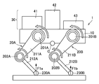
- FIG. 1 is an explanatory diagram illustrating an outline of a robot apparatus to which the information processing apparatus according to the present embodiment is applied.
- the information processing apparatus can be applied to a legged robot apparatus 1.
- the robot apparatus 1 includes, for example, four legs, and is a four-legged type that transports the transported objects 41, 42, and 43 (hereinafter, collectively referred to as the transported object 40 if they are not distinguished from each other). It is a robot device. Specifically, the robot apparatus 1 includes a main body unit 10 and a plurality of leg units 20A, 20B, 20C, and 20D (hereinafter, collectively referred to as the leg unit 20 if they are not distinguished from each other). Prepare. In FIG. 1, the leg portion 20A and the leg portion 20B are illustrated, but the same configuration as the leg portion 20A and the leg portion 20B is illustrated on the back side with respect to the paper surface of the leg portion 20A and the leg portion 20B. A leg portion 20C and a leg portion 20D are further provided.
- the main body 10 includes a housing to which a plurality of legs 20 are attached, and controls the driving of the plurality of legs 20.
- the main body 10 may include a drive motor that drives the plurality of legs 20, a control device that controls driving of the plurality of legs 20, and the like.
- a cargo portion 30 on which the transported article 40 can be placed is provided on the vertically upward rear surface of the main body portion 10.
- the drive motor may be anything as long as it can generate torque.
- the drive motor may be an electric motor that converts electrical energy into rotational motion.
- the control device controls the posture or walking of the robot device 1 by driving each of the leg portions 20 in cooperation. Specifically, the control device controls the driving of each leg portion 20 based on the position of the center of gravity of the robot device 1 so that the robot device 1 does not roll over and can walk stably.
- the cargo unit 30 holds the transported object 40 stably.
- the cargo part 30 may be configured by providing a fence for preventing the fall of the transported object 40 on the flat back surface of the main body part 10.
- the leg portion 20 is composed of a plurality of links and joints connecting the plurality of links, and a plurality of the leg portions 20 are attached to the main body portion 10. Each structure of the leg part 20 may be the same, and may mutually differ.
- the leg 20 is supported by the robot apparatus 1 and can be walked by being driven by a drive motor provided in the main body 10 or a drive motor built in the joint.
- the number of the leg portions 20 may be at least 2 in order to allow the robot apparatus 1 to walk, and the upper limit is not particularly limited. However, in order to support the robot apparatus 1 stably, the number of the leg parts 20 may be three or more. Moreover, in order to make the robot apparatus 1 walk stably, the number of the leg parts 20 may be four or more.
- the leg portion 20A may include a first joint 201A, a first link 211A, a second joint 202A, a second link 212A, and a grounding portion 230A.
- the leg portion 20B may include a first joint 201B, a first link 211B, a second joint 202B, a second link 212B, and a grounding portion 230B.
- the first joint 201 ⁇ / b> A couples the first link 211 ⁇ / b> A to the main body 10 so as to be rotatable. Specifically, the first joint 201A is coupled to one end side of the first link 211A so that the first link 211A can rotate about an axis perpendicular to the extending direction of the first link 211A. Next, the first link 211 ⁇ / b> A is coupled to the main body 10.
- the first joint 201 ⁇ / b> A may couple the first link 211 ⁇ / b> A to the main body unit 10 so that the first link 211 ⁇ / b> A can be rotated with the walking pitch axis of the robot apparatus 1 as a rotation axis. Note that the rotation range of the first joint 201A is not particularly limited.
- the first link 211A is coupled to the main body portion 10 via the first joint 201A on one end side, and is provided so as to be rotatable with respect to the main body portion 10 using the first joint 201A as a rotation axis.
- the first link 211A is coupled to one end side of the second link 212A on the other end side via the second joint 202A, and is provided so as to be rotatable with respect to the second link 212A using the second joint 202A as a rotation axis. It is done.
- the second joint 202A couples the second link 212A to the first link 211A so as to be rotatable. Specifically, the second joint 202A is coupled to one end side of the second link 212A so that the second link 212A can rotate about an axis perpendicular to the extending direction of the second link 212A. In addition, the second link 212A is coupled to the first link 211A. For example, the second joint 202A may couple the second link 212A to the first link 211A so that the second link 212A can be rotated with the walking pitch axis of the robot apparatus 1 as a rotation axis. Note that the rotation range of the second joint 202A is not particularly limited.
- the second link 212A is coupled to the other end of the first link 211A on the one end side via the second joint 202A, and is provided so as to be rotatable with respect to the first link 211A using the second joint 202A as a rotation axis. .
- a grounding portion 230A that comes into contact with the ground or the like is provided.
- the grounding part 230A is a part that comes into contact with the ground, and is provided on the tip side of the leg part 20A.
- the grounding portion 230A may be a cover or a shock absorber for protecting the leg portion 20A from the ground or the like.
- first joint 201B Regarding the first joint 201B, the first link 211B, the second joint 202B, the second link 212B, and the grounding portion 230B of the leg 20B, the first joint 201A, the first link 211A, the second joint 202A of the leg 20A, Since it is substantially the same as the second link 212A and the grounding portion 230A, description thereof is omitted here.
- Such a robot apparatus 1 is a moving body that holds and carries the transported article 40 in the cargo section 30.
- the transported object 40 is not a constant weight or shape but an arbitrary weight or shape
- the robot apparatus 1 depends on the weight or shape of the transported object 40 and the placement position of the transported object 40 in the cargo section 30.
- the posture or stability of walking may be reduced. Specifically, since the weight balance of the entire robot apparatus 1 including the transported object 40 changes when the transported object 40 is loaded, the robot apparatus 1 may roll out of balance while walking. Rise.
- the information processing apparatus estimates the position of the center of gravity of the robot apparatus 1 as a whole after the transported object 40 is loaded in the robot apparatus 1 and uses the control model based on the estimated position of the center of the robot apparatus 1. Controls walking etc. According to this, the information processing apparatus can improve the posture or the stability of walking of the robot apparatus 1 on which the object 40 having an unknown weight or shape is loaded.
- the information processing apparatus calculates reaction forces from the ground contact surface to each of the legs 20 based on the torque applied to each joint of the legs 20, and based on the calculated reaction force.
- the center of gravity position of the entire robot apparatus 1 is estimated.
- the information processing apparatus can estimate the position of the center of gravity of the entire robot apparatus 1 after the transported object 40 is loaded without using an expensive and fragile force sensor. Costs and operational costs can be reduced.
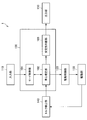
- FIG. 2 is a block diagram illustrating a functional configuration of the robot apparatus 1 including the information processing apparatus 100 according to the present embodiment.
- the information processing apparatus 100 may be provided in the main body unit 10 of the robot apparatus 1, for example.
- the robot apparatus 1 includes an input unit 110, an information processing apparatus 100, a drive control unit 120, a drive unit 130, a torque detection unit 140, and an output unit 150.
- the input unit 110 includes an input device that enables input of information from the user to the robot apparatus 1.
- the input unit 110 may include, for example, an input device to which information such as a touch panel, a button, a microphone, a switch, or a lever is input, and an input control circuit that generates an input signal based on the input information. Good.
- an instruction for controlling the robot apparatus 1 to a mode in which the user loads or unloads the transported article 40 on the robot apparatus 1 (hereinafter also referred to as a transported object replacement mode) is input to the input unit 110 by the user.
- the input unit 110 may output the input instruction to the mode control unit 101.
- the information processing apparatus 100 includes a mode control unit 101, a centroid estimation unit 102, and a stability determination unit 103.
- the mode control unit 101 controls the control state (that is, the control mode) of the robot apparatus 1. Specifically, the mode control unit 101 changes the control state of the robot apparatus 1 to the transported object replacement mode.
- the transported material transfer mode is a control state in which the user loads the transported material 40 on the cargo unit 30 of the robot apparatus 1 or unloads the transported product 40 from the cargo unit 30.
- the robot apparatus 1 In the transported object transfer mode, the robot apparatus 1 is controlled so as to maintain a predetermined posture. Specifically, regardless of the increase or decrease of the transported object 40 loaded on the cargo unit 30, each of the leg units 20 is controlled. Control is performed so that the rotation angle of the joint is maintained. As a result, the magnitude of the applied torque is applied to each joint of the leg 20 even when the load 40 loaded on the cargo unit 30 of the robot apparatus 1 increases or decreases and the weight balance of the entire robot apparatus 1 changes. Is controlled so that the rotation angle of the joint is maintained.
- the magnitude of the torque applied to each joint of the leg 20 in the transported object replacement mode depends on the weight balance of the entire robot apparatus 1 including the loaded transported object 40. Therefore, the information processing apparatus 100 can estimate the change in the center of gravity position of the entire robot apparatus 1 from the change in the torque applied to each joint of the leg 20 in the transported object replacement mode.
- the center-of-gravity estimation unit 102 estimates the center-of-gravity position of the entire robot apparatus 1 including the transported article 40 placed on the cargo unit 30 based on the torque applied to each joint of the leg unit 20.
- the center-of-gravity estimation unit 102 acquires, from the torque detection unit 140, information related to the magnitude of torque applied to the joints provided in each of the leg units 20. Subsequently, the center-of-gravity estimation unit 102 is connected to each leg 20 based on the magnitude of torque applied to the joints provided in each leg 20 and the length of the link provided in each leg 20. Determine the magnitude of the reaction force received from the ground. Next, the center-of-gravity estimation unit 102 is a plane of the center of gravity of the entire robot apparatus 1 including the transported article 40 placed on the cargo unit 30 based on the magnitude of the reaction force that each of the legs 20 receives from the ground contact surface. Estimate the position.
- the center-of-gravity estimation unit 102 when the center-of-gravity estimation unit 102 also estimates the height of the center of gravity of the entire robot apparatus 1 including the transported object 40, the center-of-gravity estimation unit 102 rotates the posture of the robot apparatus 1 around the center of gravity of the robot apparatus 1 alone. . Thereafter, the center-of-gravity estimation unit 102 estimates the plane position of the center of gravity of the entire robot apparatus 1 including the transported object 40 in a state where the posture of the robot apparatus 1 is rotated. The center-of-gravity estimation unit 102 performs geometric calculation using the plane position of the center of gravity of the robot apparatus 1 in different postures, thereby calculating the center of gravity of the entire robot apparatus 1 including the transported article 40 placed on the cargo section 30. The height can be estimated.
- the center-of-gravity estimation unit 102 may estimate the height of the center of gravity of the entire robot apparatus 1 including the transported object 40 placed on the cargo unit 30 using another method different from the method described above. Good.
- the height of the center of gravity of the entire robot apparatus 1 contributes less to the posture of the robot apparatus 1 or the stability of walking than the plane position of the center of gravity of the entire robot apparatus 1. Therefore, the center-of-gravity estimation unit 102 may change the estimation method of the height of the center of gravity of the entire robot apparatus 1 in consideration of the accuracy of information to be obtained or the calculation load.
- the information processing apparatus 100 estimates the position of the center of gravity of the entire robot apparatus 1 including the transported article 40 placed on the cargo section 30 based on the torque applied to each joint of the leg section 20. can do. Therefore, the information processing apparatus 100 can estimate the position of the center of gravity of the robot apparatus 1 without using an expensive and fragile force sensor.
- the information processing apparatus 100 re-estimates the position of the center of gravity of the entire robot apparatus 1 including the transported object 40 every time the transported object 40 is remounted on the cargo section 30. Therefore, the information processing apparatus 100 can control walking or the like of the robot apparatus 1 based on the position of the center of gravity of the entire robot apparatus 1 including the transported object 40. According to this, since the information processing apparatus 100 can change the control model for driving the robot apparatus 1 in accordance with the changed weight balance every time the weight balance of the robot apparatus 1 changes, the robot apparatus 1 posture or walking stability can be improved.
- the stability determination unit 103 determines the posture or walking stability of the robot apparatus 1 in which the cargo 40 is loaded on the cargo unit 30. Specifically, the stability determination unit 103 determines the posture of the robot apparatus 1 or the stability of walking based on the position of the center of gravity of the entire robot apparatus 1 estimated by the center of gravity estimation unit 102.
- the stability determining unit 103 is close to the center of a polygon (also referred to as a support polygon) formed by connecting the ground contact surfaces of the leg portions 20 of the robot device 1 so that the center of gravity of the robot device 1 as a whole is connected. It may be determined that the posture of the robot apparatus 1 or the stability of walking is high. Alternatively, the stability determination unit 103 determines that the posture or walking stability of the robot apparatus 1 is higher as the position of the center of gravity of the entire robot apparatus 1 including the transported object 40 is closer to the position of the center of gravity of the robot apparatus 1 alone. May be. In addition, the stability determination unit 103 may determine the placement position of the transported object 40 where the posture of the robot apparatus 1 or the stability of walking becomes higher. According to this, the information processing apparatus 100 can give a warning, suggestion, suggestion, or notification to the user via the output unit 150 so that the posture of the robot apparatus 1 or the stability of walking is higher. It becomes possible.
- a polygon also referred to as a support polygon
- the information processing apparatus 100 is, for example, in cooperation with hardware such as a CPU (Central Processing Unit), a RAM (Random Access Memory), and a ROM (Read Only Memory) and software that controls the operation of each component. Realized.
- hardware such as a CPU (Central Processing Unit), a RAM (Random Access Memory), and a ROM (Read Only Memory) and software that controls the operation of each component. Realized.
- CPU Central Processing Unit
- RAM Random Access Memory
- ROM Read Only Memory
- the CPU functions as an arithmetic processing unit, and executes information processing and information calculation in the information processing apparatus 100 in accordance with various programs stored in the ROM or the like.
- the ROM stores programs and calculation parameters used by the CPU.
- the RAM temporarily stores programs used in the execution of the CPU, parameters that change as appropriate in the execution, and the like.
- a computer program for causing hardware such as a CPU, a ROM, and a RAM built in the information processing apparatus 100 to perform the same functions as the components of the information processing apparatus according to the present embodiment.
- a storage medium storing the computer program can be provided.
- the drive control unit 120 controls the walking of the robot apparatus 1 by controlling the driving of each leg 20 of the robot apparatus 1. Specifically, the drive control unit 120 outputs a control command for controlling the rotation of the joints provided in each of the leg units 20 to the drive unit 130. Thereby, the drive control part 120 can control each drive of the leg part 20 based on kinematics.
- the drive control unit 120 controls the driving of each leg 20 of the robot apparatus 1 based on the position of the center of gravity of the robot apparatus 1 so that the robot apparatus 1 loses balance and does not roll over during walking. Also good.
- the drive control unit 120 sets the rotation angle of each joint of the leg part 20 so that the robot apparatus 1 assumes a predetermined posture. It may be fixed.
- Such a control method for driving each leg 20 based on the position of the center of gravity of the robot apparatus 1 may be stored in a storage unit or the like built in the main body 10 in advance as a control model of the robot apparatus 1, for example. Good.
- the drive control unit 120 updates the center of gravity of the robot device 1 alone in the control model of the robot device 1 with the center of gravity of the entire robot device 1 including the transported object 40, thereby enabling more stable walking and the like.
- the driving of the robot apparatus 1 can be controlled.
- the drive unit 130 generates a torque for rotating the joints provided in each of the leg units 20 based on a control command from the drive control unit 120 or the like.
- the drive unit 130 is, for example, an electric motor that performs a rotational motion using electrical energy, and may be provided for each joint of the leg unit 20.
- Each of the leg portions 20 is bent or extended by rotating each joint of the leg portion 20 by the driving unit 130.
- the torque detection unit 140 detects the magnitude of torque applied to the joint from the drive unit 130 in each of the leg units 20.
- the torque detector 140 may include a magnetostrictive, strain gauge, piezoelectric, optical, spring, or capacitive torque sensor, and may directly detect the torque applied to the joint.
- the torque detection unit 140 includes a voltmeter or an ammeter that detects the magnitude of the voltage or current applied to the driving unit 130, and based on the magnitude of the voltage or current applied to the driving unit 130, You may calculate the torque applied to.
- the magnitude of the torque detected by the torque detector 140 is used to calculate the reaction force that each of the legs 20 receives from the ground contact surface, together with the length of the link that constitutes each of the legs 20.
- the output unit 150 includes a display device or sound output device for notifying a user or the like, and an output circuit for generating image information or sound information to be output to the display device or sound output device.
- the output unit 150 may notify the user that the control state of the robot apparatus 1 has been changed to the transported object replacement mode or that the transported object replacement mode has been canceled.
- the output unit 150 is based on the determination of the stability determination unit 103, information on the posture of the robot apparatus 1 or the stability of walking, information on optimization of placement of the transport object 40 on the cargo unit 30, or transport Information regarding the load amount of the object 40 may be notified to the user.
- the output unit 150 indicates that it is difficult to transport the transported object 40 when the center of gravity position of the entire robot apparatus 1 including the transported object 40 changes by more than a threshold value from the center of gravity position of the robot apparatus 1 alone. May be notified.
- the output unit 150 provides the user with the placement position of the transported object 40 so that the amount of change between the center of gravity position of the entire robot apparatus 1 including the transported object 40 and the center of gravity position of the robot apparatus 1 alone becomes smaller. Notification may be given to suggest.
- the output unit 150 may notify the user of the weight of the transported object 40 estimated from the magnitude of the reaction force that each leg 20 receives from the ground contact surface, and is based on the weight of the loaded transported object 40. Thus, the user may be notified of the weight of the transported object 40 that can be additionally loaded on the robot apparatus 1.
- the output unit 150 may include a display device such as a CRT (Cathode Ray Tube) display device, a liquid crystal display device, or an organic EL (Organic ElectroLuminescence) display device, and may include a sound output device such as a speaker or a buzzer. .
- the output unit 150 may include a light emitter such as a light bulb, an LED (Light Emitting Diode), or a laser.
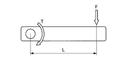
- FIG. 3 is a schematic diagram illustrating the relationship between torque and force.
- FIG. 4 is an explanatory diagram for explaining a method of calculating the plane position of the center of gravity based on the reaction force that each of the four legs receives from the ground contact surface.
- FIG. 5 is a diagram illustrating how each of the two legs is connected. It is explanatory drawing explaining the method of calculating the plane position of a gravity center based on the reaction force received from the ground.
- the mode control unit 101 fixes the rotation angle of each joint of the leg 20 by fixing the posture of the robot apparatus 1 to a predetermined posture.
- the torque applied to each joint of the leg portion 20 increases or decreases the weight due to the transported article 40 placed on the cargo portion 30 of the robot apparatus 1 by fixing the rotation angle of each joint of the leg portion 20. Will be reflected.
- the center-of-gravity estimation unit 102 calculates the reaction force that each leg 20 receives from the ground contact surface based on the torque applied to each joint of the leg 20.
- the torque T that works around the fixed rotation shaft is applied with the force F applied to the object that is rotatably coupled around the rotation shaft and the force from the rotation shaft. Expressed as the product of the distance L to the point. That is, by using the magnitude of the torque applied to the joint and the length of the link coupled to the joint, the magnitude of the force applied to the link coupled to the joint can be calculated.
- the reaction force applied from the ground contact surface applied to the ground contact portion 230A can be calculated. it can.
- the center-of-gravity estimation unit 102 estimates the plane position of the center of gravity of the entire robot apparatus 1 including the transported object 40 based on the magnitude of the reaction force received by each leg 20 from the ground contact surface.
- each of the leg portions 20 is based on the torque applied to each joint of the leg portion 20. Reaction forces f41, f42, f43, and f44 on the ground contact surfaces 231A, 231B, 231C, and 231D are calculated.
- the load center point c1 is equal to the plane position of the center of gravity of the entire robot apparatus 1 including the transported object 40. Therefore, the robot including the transported object 40 according to the above formulas 1 and 2.
- the coordinates of the plane position of the center of gravity of the entire apparatus 1 can be calculated.
- a region where the outer peripheral sides of the contact surfaces 231 ⁇ / b> A, 231 ⁇ / b> B, 231 ⁇ / b> C, and 231 ⁇ / b> D are connected by a broken line is a support polygon of the robot apparatus 1.
- the plane position of the center of gravity of the robot apparatus 1 exists inside the support polygon of the robot apparatus 1.
- the mass m d of the transported article 40 at this time can be calculated by Equation 3 below. Note that g is a gravitational acceleration, and m is the mass of the robot apparatus 1 alone.
- the plane position of the center of gravity of the entire robot apparatus 1 including the transported object 40 can be estimated as follows. Specifically, as shown in FIG. 5, first, reaction forces f21 and f22 on the ground contact surfaces 232A and 232B of the leg portion 20 are respectively calculated.
- the coordinates of the load center point c2 (COPx, COPy) can be calculated by the following equations 4 and 5.
- the robot including the transported object 40 is expressed by the above formulas 4 and 5.
- the coordinates of the plane position of the center of gravity of the entire apparatus 1 can be calculated.
- a region where the outer peripheral sides of the ground planes 232 ⁇ / b> A and 232 ⁇ / b> B are connected by a broken line is a support polygon of the robot apparatus 1.
- the plane position of the center of gravity of the robot apparatus 1 exists inside the support polygon of the robot apparatus 1.
- the mass m d of the transported article 40 at this time can be calculated by the following equation 6. Note that g is a gravitational acceleration, and m is the mass of the robot apparatus 1 alone.
- the center-of-gravity estimation unit 102 rotates the posture of the robot apparatus 1 around the center of gravity of the robot apparatus 1 alone in order to estimate the height of the center of gravity of the entire robot apparatus 1 including the transported object 40. Subsequently, the center-of-gravity estimation unit 102 similarly estimates the plane position of the center of gravity of the entire robot apparatus 1 in the post-rotation posture. Thereafter, the center-of-gravity estimation unit 102 calculates the height of the center of gravity of the entire robot apparatus 1 including the transported object 40 by performing geometric calculation using the plane position of the center of gravity of the entire robot apparatus 1 in a plurality of postures. Can be estimated.
- the center-of-gravity estimation unit 102 can estimate the height of the center of gravity of the entire robot apparatus 1 including the transported object 40 from the change in the plane position of the center of gravity before and after the rotation of the robot apparatus 1 by geometric calculation. .
- the height of the center of gravity of the entire robot apparatus 1 including the transported object 40 may be estimated by a method other than the above-described method.
- the center-of-gravity estimation unit 102 estimates the height of the center of gravity of the robot apparatus 1 on the assumption that the main body 10 on which the cargo unit 30 on which the transported object 40 is loaded is increased by the weight of the transported object 40. May be.
- the center-of-gravity estimation unit 102 uses the height of the center of gravity of the robot apparatus 1 alone to increase the height of the carriage 40 based on the ratio of the weight of the article 40 to the weight of the robot apparatus 1 alone. It may be the height of the center of gravity of the entire robot apparatus 1 including it.
- the weight of the transported object 40 is sufficiently smaller than the weight of the robot apparatus 1 alone, the height of the center of gravity of the entire robot apparatus 1 including the transported object 40 can be easily estimated even by such a method.
- FIG. 6 is a flowchart for explaining the overall flow of the operation of the information processing apparatus according to this embodiment
- FIG. 7 is a step (S150) of estimating the center of gravity of the robot apparatus 1 including the transported object in FIG. It is a flowchart figure explaining a flow in detail.
- 8 to 11 are schematic diagrams for explaining the state of the robot apparatus 1 in each step of FIG. 6 or FIG.
- the control unit 101 controls the robot apparatus 1 to the transported object replacement mode (S110).
- the user may perform an input instructing the robot apparatus 1 to shift to the transported object replacement mode.
- the mode control unit 101 fixes the rotation angle of each joint of the leg 20 so that the robot apparatus 1 assumes a predetermined posture (S120).
- the robot apparatus 1 has a horizontal loading surface of the cargo section 30 provided in the main body section 10, and the plane position of the center of gravity C of the robot apparatus 1 alone is at the center of the support polygon. You may fix to the predetermined attitude
- the output unit 150 After the posture of the robot apparatus 1 is controlled to a predetermined posture, the output unit 150 notifies the user of permission to change the load 40 (that is, loading or unloading the load 40) (S130). ).
- the notification to the user by the output unit 150 may be performed by sound output by the sound output device, may be performed by image or character display by the display device, or is performed by light emission by the light emitter. Also good.
- the robot apparatus 1 maintains the transported object replacement mode until the user inputs that the replacement of the transported object 40 has been completed.
- the transported article 40 is loaded on the cargo section 30 while maintaining a predetermined posture.
- the torque applied to each joint of the leg part 20 of the robot apparatus 1 changes with the change of the weight balance by the conveyed product 40.
- FIG. When an input is made to notify that the transfer of the transported object 40 is completed from the user (S140 / Yes), the robot apparatus 1 estimates the center of gravity of the entire robot apparatus 1 including the transported object 40 (S150). Start. On the other hand, when the input which notifies that the transfer of the conveyed product 40 was complete
- the robot apparatus 1 updates the center-of-gravity position in the control model of the robot apparatus 1 with the center-of-gravity position of the entire robot apparatus 1 including the estimated transported object 40 (S160). For example, as illustrated in FIG. 11, when the transported object 40 is loaded, the center of gravity position of the robot apparatus 1 changes from the center of gravity C of the robot apparatus 1 alone to the center of gravity Cm of the entire robot apparatus 1 including the transported object 40. The robot apparatus 1 updates the center of gravity in the control model to the center of gravity Cm. According to this, since the robot apparatus 1 can control each drive of the leg part 20 based on the weight balance reflecting the weight of the loaded transported object 40, the posture when the transported object 40 is loaded Or the stability of walking can be improved.
- the torque detector 140 detects the magnitude of the torque applied to each joint of the leg 20 of the robot apparatus 1 (S151). .
- the torque detection unit 140 reflects the torque applied to each joint of the leg unit 20 of the robot apparatus 1 reflecting the weight increase caused by the transported article 40 loaded on the cargo unit 30. To detect.
- the center-of-gravity estimation unit 102 starts from the ground contact surface to each of the legs 20 based on the magnitude of the torque applied to each joint of the legs 20 and the length of each link of the legs 20.
- the magnitude of the reaction force is estimated (S152).
- the center-of-gravity estimation unit 102 includes the legs 20A, 20B, 20C, and 20D of the robot apparatus 1 (the components of the legs 20C and 20D and the legs 20C and 20D are the legs 20A and 20B).
- Reaction forces F1a, F1b, F1c, F1d (reaction forces F1c, F1d) applied to the grounding portions 230A, 230B, 230C, 230D (grounding portions 230C, 230D are not shown) Is not shown).
- the center-of-gravity estimation unit 102 estimates the plane position of the center of gravity of the entire robot apparatus 1 including the transported object 40 based on the magnitude of the reaction force applied to each of the legs 20 from the ground contact surface (S153). For example, as illustrated in FIG. 9, the center-of-gravity estimation unit 102 calculates the load center point of the robot apparatus 1 based on the reaction forces F1a, F1b, F1c, and F1d applied to the legs 20A, 20B, 20C, and 20D. Thus, the plane position of the center of gravity of the entire robot apparatus 1 including the transported object 40 is estimated.
- the mode control unit 101 tilts the posture of the robot apparatus 1 around the center of gravity of the robot apparatus 1 alone (S154). For example, as shown in FIG. 10, the mode control unit 101 rotates the posture of the robot apparatus 1 around the pitch axis passing through the center of gravity of the robot apparatus 1.
- the torque detection unit 140 detects the magnitude of the torque applied to each joint of the leg part 20 of the robot apparatus 1 in the same manner as S151 (S155). ). For example, as shown in FIG. 10, the torque detection unit 140 detects the torque applied to each joint of the leg 20 in the posture after the rotation at each joint of the leg 20 of the robot apparatus 1.
- the center-of-gravity estimation unit 102 determines the leg portion from the ground contact surface based on the magnitude of the torque applied to each joint of the leg portion 20 and the length of each link of the leg portion 20.
- the magnitude of the reaction force applied to each of 20 is estimated (S156).
- the center of gravity estimation unit 102 includes reaction forces F2a, F2b, F2c, and the like applied to the grounding units 230A, 230B, 230C, and 230D (the grounding units 230C and 230D are not shown) in the posture after rotation.
- F2d reaction forces F2c and F2d are not shown
- the center-of-gravity estimation unit 102 calculates the center of gravity of the entire robot apparatus 1 including the transported object 40 in the post-rotation posture based on the magnitude of the reaction force applied to each of the legs 20 from the ground contact surface.
- the plane position is estimated (S157). For example, as shown in FIG. 10, the center-of-gravity estimation unit 102 is based on the reaction forces F2a, F2b, F2c, and F2d applied to the grounding units 230A, 230B, 230C, and 230D. By calculating the points, the plane position of the center of gravity of the entire robot apparatus 1 is estimated.
- the center-of-gravity estimation unit 102 estimates the height of the center of gravity of the entire robot apparatus 1 including the transported object 40 by performing geometric calculation using the plane position of the center of gravity of the entire robot apparatus 1 in different postures. (S158). As shown in FIG. 10, the plane position of the center of gravity in the posture rotated around the center of gravity of the robot apparatus 1 alone is the distance between the center of gravity of the robot apparatus 1 alone and the center of gravity of the entire robot apparatus 1 including the transported object 40. Is attributed. Therefore, the center-of-gravity estimation unit 102 performs the geometric calculation based on the change in the plane position of the center of gravity before and after the rotation of the robot apparatus 1, thereby increasing the height of the center of gravity of the entire robot apparatus 1 including the transported object 40. Can be estimated.
- the information processing apparatus 100 includes a robot including the transported article 40 placed on the cargo section 30 based on the torque applied to each joint of the leg section 20. It is possible to estimate the position of the center of gravity of the entire apparatus 1. Accordingly, the information processing apparatus 100 can estimate the position of the center of gravity of the robot apparatus 1 without using an expensive and fragile force sensor. Accordingly, the information processing apparatus 100 can estimate the center of gravity of the entire robot apparatus 1 and change the control model for driving the robot apparatus 1 in response to the change in the weight balance of the robot apparatus 1. The posture or the stability of walking can be improved.
- the information processing apparatus 100 is applied to the legged robot apparatus 1, but the present technology is not limited to such an example.
- the information processing apparatus 100 can be applied to a flying body such as a drone that flies by rotating a plurality of rotors.
- the information processing apparatus 100 may estimate the center of gravity of the drone based on the magnitude of lift generated in each of the rotors when the transported article 40 is transported to the drone. According to this, the drone can fly in a more stable posture by being controlled based on the center of gravity estimated by the information processing apparatus 100. Further, the information processing apparatus 100 can also estimate the weight of the transported object 40 loaded on the drone based on the magnitude of lift generated in each of the rotors.
- the following configurations also belong to the technical scope of the present disclosure.
- a reaction force from the ground contact surface applied to each of the plurality of legs is calculated, and the calculated plurality of legs Based on the reaction force, a center of gravity estimation unit that estimates the center of gravity of the robot apparatus including the plurality of legs, and
- An information processing apparatus comprising: (2) The robot apparatus includes a cargo section on which a transported article is loaded, The information processing apparatus according to (1), wherein the center-of-gravity estimation unit estimates a center of gravity of the robot apparatus including the transported object.
- the information processing apparatus according to any one of (1) to (7), further including a drive control unit that controls the posture or movement of the robot apparatus based on the estimated center of gravity.
- the information processing apparatus according to any one of (1) to (8), further including a stability determining unit that determines the stability of the posture of the robot apparatus based on the estimated center of gravity.
- the robot apparatus includes an output unit, The information processing apparatus according to (9), wherein the output unit performs a notification process to a user based on the determination of the stability determination unit.
- the robot apparatus is a legged robot apparatus including the four legs.
Landscapes
- Engineering & Computer Science (AREA)
- Mechanical Engineering (AREA)
- Robotics (AREA)
- Chemical & Material Sciences (AREA)
- Combustion & Propulsion (AREA)
- Transportation (AREA)
- Health & Medical Sciences (AREA)
- General Health & Medical Sciences (AREA)
- Orthopedic Medicine & Surgery (AREA)
- Human Computer Interaction (AREA)
- Manipulator (AREA)
Abstract
【課題】力センサ等を用いずにロボット装置の重心を推定する。 【解決手段】複数の脚部にそれぞれ含まれる1つ以上の関節に印加されるトルクに基づいて、前記複数の脚部の各々にかかる接地面からの反力を算出し、算出した前記複数の脚部の前記反力に基づいて、前記複数の脚部を備えるロボット装置の重心を推定する重心推定部と、を備える、情報処理装置。
Description
本開示は、情報処理装置、情報処理方法及びプログラムに関する。
近年、移動ロボットとして、脚式のロボット装置の開発が進められている。脚式のロボット装置は、車輪式のロボット装置では移動が困難な段差又は階段を含む環境、及び不整地などの環境でも自由に移動することが可能である。そのため、脚式のロボット装置は、人間が行っていた山道などでの荷物の運搬を代替することが可能な移動体として期待されている。
このような脚式のロボット装置の姿勢又は歩行を制御する技術として、様々な技術が検討されている。例えば、下記の特許文献1には、脚部の足裏に力センサを備え、力センサによるセンシング結果に基づいて荷物運搬時の重心を決定する脚式ロボットが開示されている。
しかし、特許文献1に記載の脚式ロボットは、高価な力センサを用いるため、製造コストが高かった。また、特許文献1に記載の脚式ロボットでは、大荷重がかかる脚部の足裏に力センサを設けるため、力センサが塑性変形したり、破壊されたりしやすく、頻繁な交換が必要であった。そのため、特許文献1に記載の脚式ロボットは、運用コストが高かった。
そこで、本開示では、力センサ等を用いずともロボット装置の重心を推定することが可能な、新規かつ改良された情報処理装置、情報処理方法及びプログラムを提案する。
本開示によれば、複数の脚部にそれぞれ含まれる1つ以上の関節に印加されるトルクに基づいて、前記複数の脚部の各々にかかる接地面からの反力を算出し、算出した前記複数の脚部の前記反力に基づいて、前記複数の脚部を備えるロボット装置の重心を推定する重心推定部と、を備える、情報処理装置が提供される。
また、本開示によれば、演算処理装置によって、複数の脚部にそれぞれ含まれる1つ以上の関節に印加されるトルクに基づいて、前記複数の脚部の各々にかかる接地面からの反力を算出することと、算出した前記複数の脚部の前記反力に基づいて、前記複数の脚部を備えるロボット装置の重心を推定することと、を含む、情報処理方法が提供される。
また、本開示によれば、コンピュータを、複数の脚部にそれぞれ含まれる1つ以上の関節に印加されるトルクに基づいて、前記複数の脚部の各々にかかる接地面からの反力を算出し、算出した前記複数の脚部の前記反力に基づいて、前記複数の脚部を備えるロボット装置の重心を推定する重心推定部と、として機能させる、プログラムが提供される。
本開示によれば、脚部の各々の関節に印加されるトルクと、脚部の各々のリンクの長さとに基づいて、脚部の各々に接地面から与えられる反力を推定することができるため、ロボット装置の荷重中心点を推定することが可能である。
以上説明したように本開示によれば、力センサ等を用いずともロボット装置の重心を推定することが可能である。
なお、上記の効果は必ずしも限定的なものではなく、上記の効果とともに、または上記の効果に代えて、本明細書に示されたいずれかの効果、または本明細書から把握され得る他の効果が奏されてもよい。
以下に添付図面を参照しながら、本開示の好適な実施の形態について詳細に説明する。なお、本明細書及び図面において、実質的に同一の機能構成を有する構成要素については、同一の符号を付することにより重複説明を省略する。
なお、説明は以下の順序で行うものとする。
1.概要
2.構成例
3.動作例
1.概要
2.構成例
3.動作例
<1.概要>
まず、図1を参照して、本開示の一実施形態に係る情報処理装置の概要について説明する。図1は、本実施形態に係る情報処理装置が適用されるロボット装置の概要を示す説明図である。
まず、図1を参照して、本開示の一実施形態に係る情報処理装置の概要について説明する。図1は、本実施形態に係る情報処理装置が適用されるロボット装置の概要を示す説明図である。
図1に示すように、本実施形態に係る情報処理装置は、脚式のロボット装置1に適用され得る。
ロボット装置1は、例えば、4つの脚部を備え、運搬物41、42、43(以下、これらの各々を区別しない場合には、まとめて運搬物40と称する)を運搬する四足の脚式ロボット装置である。具体的には、ロボット装置1は、本体部10と、複数の脚部20A、20B、20C、20D(以下、これらの各々を区別しない場合には、まとめて脚部20と称する)と、を備える。なお、図1では、脚部20A及び脚部20Bを図示しているが、脚部20A及び脚部20Bの紙面に対して奥側には、脚部20A及び脚部20Bと同様の構成の図示しない脚部20C及び脚部20Dがさらに備えられる。
本体部10は、複数の脚部20が取り付けられた筐体を備え、複数の脚部20の駆動を制御する。例えば、本体部10は、複数の脚部20を駆動させる駆動モータ、及び複数の脚部20の駆動を制御する制御装置などを備えてもよい。また、本体部10の鉛直上向きの背面には、運搬物40を載置可能な貨物部30が設けられる。
駆動モータは、トルクを発生させることができれば、どのようなものであってもよい。例えば、駆動モータは、電気エネルギーを回転運動に変換する電動機であってもよい。制御装置は、脚部20の各々を協働して駆動させることで、ロボット装置1の姿勢又は歩行を制御する。具体的には、制御装置は、ロボット装置1の重心位置等に基づいて、ロボット装置1が横転せず、安定して歩行することができるように脚部20の各々の駆動を制御する。貨物部30は、運搬物40を安定して保持する。例えば、貨物部30は、運搬物40の落下防止のための柵を本体部10の平坦な背面に設けることで構成されてもよい。
脚部20は、複数のリンクと、複数のリンクを連結する関節と、にて構成され、本体部10に複数取り付けられる。脚部20の各々の構造は、同一であってもよく、互いに異なっていてもよい。脚部20は、本体部10に備えられた駆動モータ、又は関節に内蔵された駆動モータによって駆動されることで、ロボット装置1を支持し、かつ歩行させることができる。
脚部20の数は、ロボット装置1の歩行を可能とするためには、少なくとも2以上であればよく、特に上限は限定されない。ただし、ロボット装置1を安定して支持するためには、脚部20の数は、3つ以上であってもよい。また、ロボット装置1を安定して歩行させるためには、脚部20の数は、4つ以上であってもよい。
例えば、図1に示すように、脚部20Aは、第1関節201Aと、第1リンク211Aと、第2関節202Aと、第2リンク212Aと、接地部230Aと、を備えて構成されてもよい。同様に、脚部20Bは、第1関節201Bと、第1リンク211Bと、第2関節202Bと、第2リンク212Bと、接地部230Bと、を備えて構成されてもよい。
第1関節201Aは、第1リンク211Aを本体部10に回動可能に結合させる。具体的には、第1関節201Aは、第1リンク211Aの一端側と結合することで、第1リンク211Aの延伸方向と垂直な軸を回転軸として第1リンク211Aが回動可能となるように、第1リンク211Aを本体部10に結合させる。例えば、第1関節201Aは、ロボット装置1の歩行のピッチ軸を回転軸として第1リンク211Aが回動可能となるように、第1リンク211Aを本体部10に結合させてもよい。なお、第1関節201Aの回動範囲は、特に限定されない。
第1リンク211Aは、一端側にて本体部10と第1関節201Aを介して結合し、本体部10に対して、第1関節201Aを回転軸として回動可能に設けられる。第1リンク211Aは、他端側にて第2リンク212Aの一端側と第2関節202Aを介して結合し、第2リンク212Aに対して、第2関節202Aを回転軸として回動可能に設けられる。
第2関節202Aは、第2リンク212Aを第1リンク211Aに回動可能に結合させる。具体的には、第2関節202Aは、第2リンク212Aの一端側と結合することで、第2リンク212Aの延伸方向と垂直な軸を回転軸として第2リンク212Aが回動可能となるように、第2リンク212Aを第1リンク211Aに結合させる。例えば、第2関節202Aは、ロボット装置1の歩行のピッチ軸を回転軸として第2リンク212Aが回動可能となるように、第2リンク212Aを第1リンク211Aに結合させてもよい。なお、第2関節202Aの回動範囲は、特に限定されない。
第2リンク212Aは、一端側にて第1リンク211Aの他端側と第2関節202Aを介して結合し、第1リンク211Aに対して第2関節202Aを回転軸として回動可能に設けられる。第1リンク201の他端側には、地面等に当接する接地部230Aが設けられる。
接地部230Aは、地面と当接する部位であり、脚部20Aの先端側に設けられる。例えば、接地部230Aは、地面等から脚部20Aを保護するためのカバー又は衝撃吸収材等であってもよい。
脚部20Bの第1関節201B、第1リンク211B、第2関節202B、第2リンク212B、及び接地部230Bについては、脚部20Aの第1関節201A、第1リンク211A、第2関節202A、第2リンク212A、及び接地部230Aと実質的に同様であるため、ここでの説明は省略する。
このようなロボット装置1は、運搬物40を貨物部30に保持して運搬する移動体である。ここで、運搬物40は、一定の重量又は形状ではなく、任意の重量又は形状であるため、運搬物40の重量若しくは形状、貨物部30における運搬物40の載置位置によっては、ロボット装置1の姿勢又は歩行の安定性が低下することがあり得る。具体的には、ロボット装置1は、運搬物40を積載することによって、運搬物40を含むロボット装置1全体での重量バランスが変化するため、歩行時にバランスを崩して横転してしまう可能性が高まる。
本実施形態に係る情報処理装置は、このようなロボット装置1において、運搬物40を積載した後のロボット装置1全体での重心位置を推定し、推定した重心位置に基づく制御モデルによってロボット装置1の歩行等を制御する。これによれば、情報処理装置は、未知の重量又は形状の運搬物40が積載されたロボット装置1の姿勢又は歩行の安定性を向上させることができる。
また、本実施形態に係る情報処理装置は、脚部20の各々の関節に印加されるトルクに基づいて脚部20の各々への接地面からの反力を算出し、算出した反力に基づいてロボット装置1全体での重心位置を推定する。これによれば、情報処理装置は、高価かつ壊れやすい力センサを用いずに、運搬物40を積載した後のロボット装置1全体での重心位置を推定することができるため、ロボット装置1の製造コスト及び運用コストを低減することができる。
以下では、上記で概要を説明した本実施形態に係る情報処理装置の構成について、より具体的に説明する。
<2.構成例>
続いて、図2を参照して、本実施形態に係る情報処理装置の構成例について説明する。図2は、本実施形態に係る情報処理装置100を含むロボット装置1の機能構成を示すブロック図である。なお、情報処理装置100は、例えば、ロボット装置1の本体部10に備えられてもよい。
続いて、図2を参照して、本実施形態に係る情報処理装置の構成例について説明する。図2は、本実施形態に係る情報処理装置100を含むロボット装置1の機能構成を示すブロック図である。なお、情報処理装置100は、例えば、ロボット装置1の本体部10に備えられてもよい。
図2に示すように、ロボット装置1は、入力部110と、情報処理装置100と、駆動制御部120と、駆動部130と、トルク検出部140と、出力部150と、を備える。
入力部110は、ユーザからロボット装置1への情報の入力を可能とする入力装置を含む。入力部110は、例えば、タッチパネル、ボタン、マイクロフォン、スイッチ又はレバーなどの情報が入力される入力装置と、入力された情報に基づいて入力信号を生成する入力制御回路とを含んで構成されてもよい。例えば、入力部110には、ユーザによって、ロボット装置1に運搬物40を積載する、又は荷下ろしするモード(以下では、運搬物載せ替えモードとも称する)にロボット装置1を制御するための指示が入力され、入力部110は、入力された該指示をモード制御部101へ出力してもよい。
情報処理装置100は、モード制御部101と、重心推定部102と、安定性判断部103と、を備える。
モード制御部101は、ロボット装置1の制御状態(すなわち、制御モード)を制御する。具体的には、モード制御部101は、ロボット装置1の制御状態を運搬物載せ替えモードに変更する。運搬物載せ替えモードは、ユーザがロボット装置1の貨物部30に運搬物40を積載する、又は貨物部30から運搬物40を荷下ろしするための制御状態である。
運搬物載せ替えモードでは、ロボット装置1は、所定の姿勢を維持するように制御され、具体的には、貨物部30に積載される運搬物40の増減に関わらず、脚部20の各々の関節の回動角度が維持されるように制御される。これにより、脚部20の各々の関節は、ロボット装置1の貨物部30に積載される運搬物40が増減し、ロボット装置1全体の重量バランスが変化した場合でも、印加されるトルクの大きさを変化させることで、関節の回動角度を維持するように制御される。
したがって、運搬物載せ替えモードにおける脚部20の各々の関節に印加されるトルクの大きさは、積載された運搬物40を含むロボット装置1全体の重量バランスに依存することになる。よって、情報処理装置100は、運搬物載せ替えモードにおける脚部20の各々の関節に印加されるトルクの変化から、ロボット装置1全体の重心位置の変化を推定することが可能になる。
重心推定部102は、脚部20の各々の関節に印加されるトルクに基づいて、貨物部30に載置された運搬物40を含むロボット装置1全体での重心位置を推定する。
具体的には、まず、重心推定部102は、脚部20の各々に備えられる関節に印加されるトルクの大きさに関する情報をトルク検出部140から取得する。続いて、重心推定部102は、脚部20の各々に備えられる関節に印加されるトルクの大きさと、脚部20の各々に備えられるリンクの長さとに基づいて、脚部20の各々が接地面から受ける反力の大きさを判断する。次に、重心推定部102は、脚部20の各々が接地面から受ける反力の大きさに基づいて、貨物部30に載置された運搬物40を含むロボット装置1全体での重心の平面位置を推定する。
さらに、重心推定部102が運搬物40を含むロボット装置1全体での重心の高さも推定する場合、重心推定部102は、ロボット装置1単体での重心を中心としてロボット装置1の姿勢を回転させる。その後、重心推定部102は、ロボット装置1の姿勢を回転させた状態での運搬物40を含むロボット装置1全体での重心の平面位置を推定する。重心推定部102は、異なる姿勢のロボット装置1の重心の平面位置を用いて幾何的に演算を行うことで、貨物部30に載置された運搬物40を含むロボット装置1全体での重心の高さを推定することができる。
なお、重心推定部102は、貨物部30に載置された運搬物40を含むロボット装置1全体での重心の高さについては、上述した方法とは異なる他の方法を用いて推定してもよい。ロボット装置1全体での重心の高さは、ロボット装置1全体での重心の平面位置よりも、ロボット装置1の姿勢又は歩行の安定性への寄与が小さい。そのため、重心推定部102は、得られる情報の精度又は演算負荷を考慮して、ロボット装置1全体での重心の高さの推定方法を変更してもよい。
本実施形態に係る情報処理装置100は、脚部20の各々の関節に印加されるトルクに基づいて、貨物部30に載置された運搬物40を含むロボット装置1全体での重心位置を推定することができる。したがって、情報処理装置100は、高価かつ壊れやすい力センサを用いずとも、ロボット装置1の重心位置を推定することができる。
また、本実施形態に係る情報処理装置100は、貨物部30への運搬物40の載せ替えのたびに、運搬物40も含めたロボット装置1全体の重心位置を推定し直す。したがって、情報処理装置100は、運搬物40も含めたロボット装置1全体の重心位置に基づいてロボット装置1の歩行等を制御することが可能である。これによれば、情報処理装置100は、ロボット装置1の重量バランスが変化するたびに、変化後の重量バランスに対応してロボット装置1の駆動の制御モデルを変更することができるため、ロボット装置1の姿勢又は歩行の安定性を向上させることができる。
安定性判断部103は、貨物部30に運搬物40を積載したロボット装置1の姿勢又は歩行の安定性を判断する。具体的には、安定性判断部103は、重心推定部102によって推定されたロボット装置1全体での重心位置に基づいて、ロボット装置1の姿勢又は歩行の安定性を判断する。
例えば、安定性判断部103は、ロボット装置1全体での重心位置がロボット装置1の脚部20の各々の接地面を結ぶことで形成される多角形(支持多角形ともいう)の中心に近いほど、ロボット装置1の姿勢又は歩行の安定性が高いと判断してもよい。または、安定性判断部103は、運搬物40を含むロボット装置1全体での重心位置がロボット装置1単体での重心位置に近いほど、ロボット装置1の姿勢又は歩行の安定性が高いと判断してもよい。また、安定性判断部103は、ロボット装置1の姿勢又は歩行の安定性がより高くなる運搬物40の載置位置を判断してもよい。これによれば、情報処理装置100は、ロボット装置1の姿勢又は歩行の安定性がより高くなるように、出力部150を介してユーザに対して警告、示唆、提案又は通知等をすることが可能になる。
なお、情報処理装置100は、例えば、CPU(Central Processing Unit)、RAM(Random Access Memory)、及びROM(Read Only Memory)などのハードウェアと、各構成の動作を制御するソフトウェアとの協働によって実現される。
CPUは、演算処理装置として機能し、ROM等に記憶された各種プログラムに従って、情報処理装置100における情報処理および情報演算の全般を実行する。ROMは、CPUが使用するプログラム及び演算パラメータを記憶する。RAMは、CPUの実行において使用するプログラム、及びその実行において適宜変化するパラメータ等を一時記憶する。これらCPU、ROM及びRAMは、例えば、内部バスまたはブリッジ等により相互に接続される。
また、情報処理装置100に内蔵されるCPU、ROM及びRAMなどのハードウェアに対して、本実施形態に係る情報処理装置の各構成と同等の機能を発揮させるためのコンピュータプログラムも作成可能である。さらに、該コンピュータプログラムを記憶させた記憶媒体も提供することが可能である。
駆動制御部120は、ロボット装置1の脚部20の各々の駆動を制御することで、ロボット装置1の歩行を制御する。具体的には、駆動制御部120は、脚部20の各々に設けられた関節の回動を制御する制御指令を駆動部130に出力する。これにより、駆動制御部120は、運動学に基づいて脚部20の各々の駆動を制御することができる。
例えば、駆動制御部120は、ロボット装置1の重心位置に基づいて、歩行の際にロボット装置1がバランスを崩して横転しないように、ロボット装置1の脚部20の各々の駆動を制御してもよい。また、駆動制御部120は、ロボット装置1の制御状態が運搬物載せ替えモードに変更された場合、ロボット装置1が所定の姿勢になるように、脚部20の各々の関節の回動角度を固定してもよい。
このようなロボット装置1の重心位置に基づく脚部20の各々の駆動の制御方法は、例えば、ロボット装置1の制御モデルとして、あらかじめ本体部10に内蔵される記憶部等に格納されていてもよい。駆動制御部120は、ロボット装置1の制御モデルにおけるロボット装置1単体の重心位置を、運搬物40を含むロボット装置1全体の重心位置にて更新することで、より安定した歩行等が可能なようにロボット装置1の駆動を制御することができる。
駆動部130は、駆動制御部120からの制御指令等に基づいて、脚部20の各々に備えられる関節を回動させるトルクを発生させる。駆動部130は、例えば、電気エネルギーによって回転運動を行う電動機であり、脚部20の各々の関節ごとに設けられてもよい。脚部20の各々は、駆動部130によって脚部20の各々の関節が回動されることで、屈曲又は伸展される。
トルク検出部140は、脚部20の各々において、駆動部130から関節に印加されるトルクの大きさを検出する。トルク検出部140は、磁歪式、ひずみゲージ式、圧電式、光学式、ばね式又は静電容量式のトルクセンサを含み、関節に印加されるトルクを直接検出してもよい。または、トルク検出部140は、駆動部130に印加される電圧又は電流の大きさを検出する電圧計又は電流計を含み、駆動部130に印加される電圧又は電流の大きさに基づいて、関節に印加されるトルクを算出してもよい。トルク検出部140が検出したトルクの大きさは、脚部20の各々を構成するリンクの長さと併せて、脚部20の各々が接地面から受ける反力を算出するために用いられる。
出力部150は、ユーザ等に対して通知を行うための表示装置又は音声出力装置と、表示装置又は音声出力装置に出力する画像情報又は音声情報を生成する出力回路と、を含む。出力部150は、例えば、ロボット装置1の制御状態を運搬物載せ替えモードに変更したこと、又は運搬物載せ替えモードを解除したことをユーザに対して通知してもよい。また、出力部150は、安定性判断部103の判断に基づいて、ロボット装置1の姿勢又は歩行の安定性に関する情報、運搬物40の貨物部30への載置の最適化に関する情報、又は運搬物40の積載量に関する情報をユーザに対して通知してもよい。
例えば、出力部150は、運搬物40を含むロボット装置1全体での重心位置がロボット装置1単体での重心位置から閾値以上変化している場合、運搬物40の運搬が困難であることをユーザに通知してもよい。または、出力部150は、運搬物40を含むロボット装置1全体での重心位置と、ロボット装置1単体での重心位置との変化量がより小さくなるような運搬物40の載置位置をユーザに対して示唆する通知を行ってもよい。または、出力部150は、脚部20の各々が接地面から受ける反力の大きさから推定された運搬物40の重量をユーザに通知してもよく、積載された運搬物40の重量に基づいて、ロボット装置1に追加で積載可能な運搬物40の重量をユーザに通知してもよい。
出力部150は、例えば、CRT(Cathode Ray Tube)表示装置、液晶表示装置、又は有機EL(Organic ElectroLuminescence)表示装置などの表示装置を含んでもよく、スピーカ又はブザーなどの音声出力装置を含んでもよい。また、出力部150は、電球、LED(Light Emitting Diode)又はレーザなどの発光器を含んでもよい。
続いて、図3~図5を参照して、本実施形態に係る情報処理装置100によるロボット装置1の重心位置を推定する具体的な方法について説明する。図3は、トルク及び力の関係を説明する模式図である。また、図4は、4つの脚部の各々が接地面から受ける反力に基づいて重心の平面位置を算出する方法を説明する説明図であり、図5は、2つの脚部の各々が接地面から受ける反力に基づいて重心の平面位置を算出する方法を説明する説明図である。
まず、モード制御部101は、ロボット装置1の姿勢を所定の姿勢に固定することで、脚部20の各々の関節の回動角度を固定する。脚部20の各々の関節に印加されるトルクは、脚部20の各々の関節の回動角度を固定することによって、ロボット装置1の貨物部30に載置される運搬物40による重量の増減を反映したものとなる。
次に、重心推定部102は、脚部20の各々の関節に印加されるトルクに基づいて、脚部20の各々が接地面から受ける反力を算出する。ここで、図3に示すように、固定された回転軸を中心として働くトルクTは、回転軸を中心として回動可能に結合された物体に加えられる力Fと、回転軸から力が加えられる点までの距離Lとの積として表される。すなわち、関節に印加されるトルクの大きさと、関節に結合されたリンクの長さとを用いることで、関節に結合されたリンクに加えられる力の大きさを算出することができる。例えば、第2関節202Aに印加されるトルクと、第2関節202Aに結合される第2リンク212Aの長さとを用いることで、接地部230Aに加えられる接地面からの反力を算出することができる。
続いて、重心推定部102は、脚部20の各々が接地面から受けている反力の大きさに基づいて、運搬物40を含むロボット装置1全体の重心の平面位置を推定する。
例えば、ロボット装置1が4つの脚部20を備える脚式のロボット装置である場合、図4に示すように、脚部20の各々の関節に印加されるトルクに基づいて、脚部20の各々の接地面231A、231B、231C、231Dにおける反力f41、f42、f43、f44がそれぞれ算出される。
ここで、接地面231A、231Bが配列する方向にY軸を取り、接地面231B、231Dが配列し、Y軸と直交する方向にX軸を取ると、荷重中心点c1の座標(COPx,COPy)は、以下の式1及び式2で算出することができる。
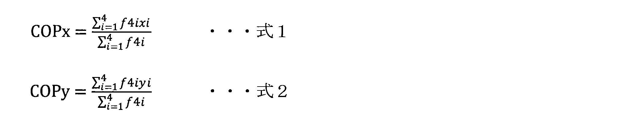
ロボット装置1が静止状態である場合、荷重中心点c1は、運搬物40を含むロボット装置1全体の重心の平面位置と等しくなるため、上記の式1及び式2により、運搬物40を含むロボット装置1全体の重心の平面位置の座標を算出することができる。なお、図4において、接地面231A、231B、231C、231Dの外周の辺を破線で結んだ領域は、ロボット装置1の支持多角形となる。ロボット装置1がバランスを崩して横転しないためには、ロボット装置1の重心の平面位置は、ロボット装置1の支持多角形の内部に存在することになる。
また、このときの運搬物40の質量mdは、以下の式3にて算出することができる。なお、gは、重力加速度であり、mは、ロボット装置1単体の質量である。

同様に、例えば、ロボット装置1が2つの脚部20を備える脚式のロボット装置である場合、以下のように、運搬物40を含むロボット装置1全体の重心の平面位置を推定することができる。具体的には、図5に示すように、まず、脚部20の各々の接地面232A、232Bにおける反力f21、f22がそれぞれ算出される。
ここで、例えば、図5に正対して上下方向にY軸を取り、図5に正対して左右方向(すなわち、Y軸と直交する方向)にX軸を取ると、荷重中心点c2の座標(COPx,COPy)は、以下の式4及び式5で算出することができる。

ロボット装置1が静止状態である場合、荷重中心点c2は、運搬物40を含むロボット装置1全体の重心の平面位置と等しくなるため、上記の式4及び式5により、運搬物40を含むロボット装置1全体の重心の平面位置の座標を算出することができる。なお、図5において、接地面232A、232Bの外周の辺を破線で結んだ領域は、ロボット装置1の支持多角形となる。ロボット装置1がバランスを崩して横転しないためには、ロボット装置1の重心の平面位置は、ロボット装置1の支持多角形の内部に存在することになる。
また、このときの運搬物40の質量mdは、以下の式6にて算出することができる。なお、gは、重力加速度であり、mは、ロボット装置1単体の質量である。

さらに、重心推定部102は、運搬物40を含むロボット装置1全体での重心の高さを推定するために、ロボット装置1単体での重心を中心としてロボット装置1の姿勢を回転させる。続いて、重心推定部102は、回転後の姿勢において同様にロボット装置1全体での重心の平面位置を推定する。その後、重心推定部102は、複数の姿勢におけるロボット装置1全体での重心の平面位置を用いて幾何的な計算を行うことで、運搬物40を含むロボット装置1全体での重心の高さを推定することができる。
ロボット装置1単体での重心を中心としてロボット装置1の姿勢を回転させた場合、回転前後での重心の平面位置の変化量は、ロボット装置1単体の重心と、運搬物40を含むロボット装置1全体の重心との距離に起因する量となる。したがって、重心推定部102は、幾何的な計算によって、ロボット装置1の回転前後での重心の平面位置の変化から運搬物40を含むロボット装置1全体での重心の高さを推定することができる。
なお、運搬物40を含むロボット装置1全体での重心の高さは、上述した以外の方法によって推定されてもよい。例えば、重心推定部102は、運搬物40を積載する貨物部30が設けられる本体部10が運搬物40の重量の分だけ重くなったと仮定して、ロボット装置1の重心の高さを推定してもよい。具体的には、重心推定部102は、ロボット装置1単体の重量に対する運搬物40の重量の割合に基づいて、ロボット装置1単体の重心の高さを増加させた高さを、運搬物40を含むロボット装置1全体の重心の高さとしてもよい。運搬物40の重量がロボット装置1単体の重量よりも十分に小さい場合、このような方法でも運搬物40を含むロボット装置1全体での重心の高さを簡易的に推定することができる。
<3.動作例>
次に、図6~図11を参照して、本実施形態に係る情報処理装置の動作例について説明する。図6は、本実施形態に係る情報処理装置の動作の全体の流れを説明するフローチャート図であり、図7は、図6の運搬物を含むロボット装置1の重心を推定するステップ(S150)の流れをより詳細に説明するフローチャート図である。また、図8~図11は、図6又は図7の各ステップにおけるロボット装置1の状態を説明する模式図である。
次に、図6~図11を参照して、本実施形態に係る情報処理装置の動作例について説明する。図6は、本実施形態に係る情報処理装置の動作の全体の流れを説明するフローチャート図であり、図7は、図6の運搬物を含むロボット装置1の重心を推定するステップ(S150)の流れをより詳細に説明するフローチャート図である。また、図8~図11は、図6又は図7の各ステップにおけるロボット装置1の状態を説明する模式図である。
図6に示すように、ユーザからロボット装置1に対して、ロボット装置1に運搬物40を載せ替え(すなわち、運搬物40の積載又は荷下ろし)を行う旨の指示が入力された場合、モード制御部101は、ロボット装置1を運搬物載せ替えモードに制御する(S110)。例えば、ユーザは、運搬物40によってロボット装置1の重量バランスを変化させる可能性がある場合、ロボット装置1に対して運搬物載せ替えモードに遷移するように指示する入力を行ってもよい。
これにより、モード制御部101は、ロボット装置1が所定の姿勢になるように脚部20の各々の関節の回動角度を固定する(S120)。例えば、ロボット装置1は、図8に示すように、本体部10に設けられた貨物部30の載置面が水平となり、かつロボット装置1単体の重心Cの平面位置が支持多角形の中心に近い位置となるような所定の姿勢に固定されてもよい。すなわち、ロボット装置1は、運搬物40を貨物部30に積載しやすく、かつロボット装置1の安定性が高くなるような所定の姿勢に固定されてもよい。
ロボット装置1の姿勢が所定の姿勢に制御された後、出力部150は、ユーザに対して運搬物40の載せ替え(すなわち、運搬物40の積載又は荷下ろし)を許可する通知を行う(S130)。なお、出力部150によるユーザへの通知は、音声出力装置による音声出力にて行われてもよく、表示装置による画像又は文字表示にて行われてもよく、発光器による発光にて行われてもよい。
その後、ロボット装置1は、ユーザから運搬物40の載せ替えを終了した旨を入力されるまで運搬物載せ替えモードを維持する。このとき、例えば、ロボット装置1では、図9に示すように、所定の姿勢を維持したまま、貨物部30に運搬物40が積載されることになる。これにより、ロボット装置1の脚部20の各々の関節に印加されるトルクは、運搬物40による重量バランスの変化に伴って変化する。ユーザから運搬物40の載せ替えが終了した旨を通知する入力が行われた場合(S140/Yes)、ロボット装置1は、運搬物40を含むロボット装置1全体の重心位置の推定(S150)を開始する。一方、ユーザから運搬物40の載せ替えが終了した旨を通知する入力が行われていない場合(S140/No)、ロボット装置1は、運搬物載せ替えモードを維持する。
さらに、ロボット装置1は、推定された運搬物40を含むロボット装置1全体の重心位置にて、ロボット装置1の制御モデルにおける重心位置を更新する(S160)。例えば、図11に示すように、運搬物40が積載されることで、ロボット装置1の重心位置がロボット装置1単体の重心Cから運搬物40を含むロボット装置1全体の重心Cmに変化した場合、ロボット装置1は、制御モデルにおける重心を重心Cmに更新する。これによれば、ロボット装置1は、積載された運搬物40の重量を反映した重量バランスに基づいて、脚部20の各々の駆動を制御することができるため、運搬物40を積載時の姿勢又は歩行の安定性を向上させることができる。
続いて、図7を参照して、運搬物を含むロボット装置1の重心を推定するステップ(S150)の流れをより詳細に説明する。
図7に示すように、重心を推定するステップ(S150)では、まず、トルク検出部140は、ロボット装置1の脚部20の各々の関節に印加されるトルクの大きさを検出する(S151)。例えば、図9に示すように、トルク検出部140は、ロボット装置1の脚部20の各々の関節において、貨物部30に積載される運搬物40による重量増加を反映して印加されたトルクを検出する。
続いて、重心推定部102は、脚部20の各々の関節に印加されるトルクの大きさ、及び脚部20の各々のリンクの長さに基づいて、接地面から脚部20の各々にかかる反力の大きさを推定する(S152)。例えば、図9に示すように、重心推定部102は、ロボット装置1の脚部20A、20B、20C、20D(脚部20C、20D及び脚部20C、20Dの各構成は、脚部20A、20Bの紙面奥側に存在し、図示されず)の接地部230A、230B、230C、230D(接地部230C、230Dは図示されず)にかかる反力F1a、F1b、F1c、F1d(反力F1c、F1dは図示されず)を推定する。
次に、重心推定部102は、接地面から脚部20の各々にかかる反力の大きさに基づいて、運搬物40を含むロボット装置1全体の重心の平面位置を推定する(S153)。例えば、図9に示すように、重心推定部102は、脚部20A、20B、20C、20Dにかかる反力F1a、F1b、F1c、F1dに基づいて、ロボット装置1の荷重中心点を算出することで、運搬物40を含むロボット装置1全体の重心の平面位置を推定する。
続いて、モード制御部101は、ロボット装置1の姿勢をロボット装置1単体の重心を中心として傾ける(S154)。例えば、図10に示すように、モード制御部101は、ロボット装置1の重心を通るピッチ軸を中心として、ロボット装置1の姿勢を回転させる。
次に、姿勢を回転させた後のロボット装置1において、S151と同様に、トルク検出部140は、ロボット装置1の脚部20の各々の関節に印加されるトルクの大きさを検出する(S155)。例えば、図10に示すように、トルク検出部140は、ロボット装置1の脚部20の各々の関節において、回転後の姿勢における脚部20の各々の関節に印加されたトルクを検出する。
続いて、S152と同様に、重心推定部102は、脚部20の各々の関節に印加されるトルクの大きさ、及び脚部20の各々のリンクの長さに基づいて、接地面から脚部20の各々にかかる反力の大きさを推定する(S156)。例えば、図10に示すように、重心推定部102は、回転後の姿勢における接地部230A、230B、230C、230D(接地部230C、230Dは図示されず)にかかる反力F2a、F2b、F2c、F2d(反力F2c、F2dは図示されず)を推定する。
次に、S153と同様に、重心推定部102は、接地面から脚部20の各々にかかる反力の大きさに基づいて、回転後の姿勢における運搬物40を含むロボット装置1全体の重心の平面位置を推定する(S157)。例えば、図10に示すように、重心推定部102は、接地部230A、230B、230C、230Dにかかる反力F2a、F2b、F2c、F2dに基づいて、回転後の姿勢におけるロボット装置1の荷重中心点を算出することで、ロボット装置1全体の重心の平面位置を推定する。
その後、重心推定部102は、異なる姿勢におけるロボット装置1全体での重心の平面位置を用いて幾何的な計算を行うことで、運搬物40を含むロボット装置1全体での重心の高さを推定する(S158)。図10に示すように、ロボット装置1単体での重心を中心に回転した姿勢における重心の平面位置は、ロボット装置1単体の重心と、運搬物40を含むロボット装置1全体の重心との距離に起因している。したがって、重心推定部102は、ロボット装置1の回転前後での重心の平面位置の変化に基づいて、幾何的な計算をすることで、運搬物40を含むロボット装置1全体での重心の高さを推定することができる。
以上のような動作によれば、本実施形態に係る情報処理装置100は、脚部20の各々の関節に印加されるトルクに基づいて、貨物部30に載置された運搬物40を含むロボット装置1全体での重心位置を推定することが可能である。これによれば、情報処理装置100は、高価かつ壊れやすい力センサを用いずとも、ロボット装置1の重心位置を推定することができる。したがって、情報処理装置100は、ロボット装置1の重量バランスの変化に対応して、ロボット装置1全体の重心を推定し、ロボット装置1の駆動の制御モデルを変更することができるため、ロボット装置1の姿勢又は歩行の安定性を向上させることができる。
以上、添付図面を参照しながら本開示の好適な実施形態について詳細に説明したが、本開示の技術的範囲はかかる例に限定されない。本開示の技術分野における通常の知識を有する者であれば、特許請求の範囲に記載された技術的思想の範疇内において、各種の変更例または修正例に想到し得ることは明らかであり、これらについても、当然に本開示の技術的範囲に属するものと了解される。
上記実施形態では、情報処理装置100は、脚式のロボット装置1に適用されるとしたが、本技術はかかる例に限定されない。例えば、情報処理装置100は、複数のロータを回転させることで飛行するドローン等の飛行体に適用することも可能である。具体的には、情報処理装置100は、運搬物40をドローンに運搬させる際に、ロータの各々にて発生させる揚力の大きさによって、ドローンの重心を推定してもよい。これによれば、ドローンは、情報処理装置100によって推定された重心に基づいて制御されることで、より安定した姿勢にて飛行することが可能となる。また、情報処理装置100は、ロータの各々にて発生された揚力の大きさによって、ドローンに積載させた運搬物40の重量を推定することも可能である。
また、本明細書に記載された効果は、あくまで説明的または例示的なものであって限定的ではない。つまり、本開示に係る技術は、上記の効果とともに、または上記の効果に代えて、本明細書の記載から当業者には明らかな他の効果を奏しうる。
なお、以下のような構成も本開示の技術的範囲に属する。
(1)
複数の脚部にそれぞれ含まれる1つ以上の関節に印加されるトルクに基づいて、前記複数の脚部の各々にかかる接地面からの反力を算出し、算出した前記複数の脚部の前記反力に基づいて、前記複数の脚部を備えるロボット装置の重心を推定する重心推定部と、
を備える、情報処理装置。
(2)
前記ロボット装置は、運搬物が積載される貨物部を備え、
前記重心推定部は、前記運搬物を含んだ前記ロボット装置の重心を推定する、前記(1)に記載の情報処理装置。
(3)
前記ロボット装置を所定の姿勢に制御することで、前記関節の回動角度が一定になるように制御するモード制御部をさらに備え、
前記重心推定部は、前記運搬物の積み降ろし前後での前記関節に印加されるトルクの変化に基づいて、前記ロボット装置の重心を推定する、前記(2)に記載の情報処理装置。
(4)
前記脚部は、複数のリンク、及び1つ以上の関節で構成され、
前記重心推定部は、前記リンクの長さ、及び前記関節に印加されるトルクの大きさに基づいて、前記脚部にかかる接地面からの反力を算出する、前記(1)~(3)のいずれか一項に記載の情報処理装置。
(5)
前記重心推定部は、算出した前記複数の脚部の前記反力に基づいて、前記ロボット装置の重心の平面位置を推定する、前記(1)~(4)のいずれか一項に記載の情報処理装置。
(6)
前記重心推定部は、前記ロボット装置の複数の姿勢において算出した前記複数の脚部のそれぞれの前記反力に基づいて、前記ロボット装置の重心の高さを推定する、前記(1)~(5)のいずれか一項に記載の情報処理装置。
(7)
前記複数の姿勢は、前記ロボット装置の単体での重心を中心として互いに回転させた前記ロボット装置の姿勢である、前記(6)に記載の情報処理装置。
(8)
推定された前記重心に基づいて、前記ロボット装置の姿勢又は移動を制御する駆動制御部をさらに備える、前記(1)~(7)のいずれか一項に記載の情報処理装置。
(9)
推定された前記重心に基づいて、前記ロボット装置の姿勢の安定性を判断する安定性判断部をさらに備える、前記(1)~(8)のいずれか一項に記載の情報処理装置。
(10)
前記ロボット装置は、出力部を備え、
前記出力部は、前記安定性判断部の判断に基づいて、ユーザへの通知処理を行う、前記(9)に記載の情報処理装置。
(11)
前記ロボット装置は、4つの前記脚部を備える脚式のロボット装置である、前記(1)~(10)のいずれか一項に記載の情報処理装置。
(12)
演算処理装置によって、
複数の脚部にそれぞれ含まれる1つ以上の関節に印加されるトルクに基づいて、前記複数の脚部の各々にかかる接地面からの反力を算出することと、
算出した前記複数の脚部の前記反力に基づいて、前記複数の脚部を備えるロボット装置の重心を推定することと、
を含む、情報処理方法。
(13)
コンピュータを、
複数の脚部にそれぞれ含まれる1つ以上の関節に印加されるトルクに基づいて、前記複数の脚部の各々にかかる接地面からの反力を算出し、算出した前記複数の脚部の前記反力に基づいて、前記複数の脚部を備えるロボット装置の重心を推定する重心推定部と、
として機能させる、プログラム。
(1)
複数の脚部にそれぞれ含まれる1つ以上の関節に印加されるトルクに基づいて、前記複数の脚部の各々にかかる接地面からの反力を算出し、算出した前記複数の脚部の前記反力に基づいて、前記複数の脚部を備えるロボット装置の重心を推定する重心推定部と、
を備える、情報処理装置。
(2)
前記ロボット装置は、運搬物が積載される貨物部を備え、
前記重心推定部は、前記運搬物を含んだ前記ロボット装置の重心を推定する、前記(1)に記載の情報処理装置。
(3)
前記ロボット装置を所定の姿勢に制御することで、前記関節の回動角度が一定になるように制御するモード制御部をさらに備え、
前記重心推定部は、前記運搬物の積み降ろし前後での前記関節に印加されるトルクの変化に基づいて、前記ロボット装置の重心を推定する、前記(2)に記載の情報処理装置。
(4)
前記脚部は、複数のリンク、及び1つ以上の関節で構成され、
前記重心推定部は、前記リンクの長さ、及び前記関節に印加されるトルクの大きさに基づいて、前記脚部にかかる接地面からの反力を算出する、前記(1)~(3)のいずれか一項に記載の情報処理装置。
(5)
前記重心推定部は、算出した前記複数の脚部の前記反力に基づいて、前記ロボット装置の重心の平面位置を推定する、前記(1)~(4)のいずれか一項に記載の情報処理装置。
(6)
前記重心推定部は、前記ロボット装置の複数の姿勢において算出した前記複数の脚部のそれぞれの前記反力に基づいて、前記ロボット装置の重心の高さを推定する、前記(1)~(5)のいずれか一項に記載の情報処理装置。
(7)
前記複数の姿勢は、前記ロボット装置の単体での重心を中心として互いに回転させた前記ロボット装置の姿勢である、前記(6)に記載の情報処理装置。
(8)
推定された前記重心に基づいて、前記ロボット装置の姿勢又は移動を制御する駆動制御部をさらに備える、前記(1)~(7)のいずれか一項に記載の情報処理装置。
(9)
推定された前記重心に基づいて、前記ロボット装置の姿勢の安定性を判断する安定性判断部をさらに備える、前記(1)~(8)のいずれか一項に記載の情報処理装置。
(10)
前記ロボット装置は、出力部を備え、
前記出力部は、前記安定性判断部の判断に基づいて、ユーザへの通知処理を行う、前記(9)に記載の情報処理装置。
(11)
前記ロボット装置は、4つの前記脚部を備える脚式のロボット装置である、前記(1)~(10)のいずれか一項に記載の情報処理装置。
(12)
演算処理装置によって、
複数の脚部にそれぞれ含まれる1つ以上の関節に印加されるトルクに基づいて、前記複数の脚部の各々にかかる接地面からの反力を算出することと、
算出した前記複数の脚部の前記反力に基づいて、前記複数の脚部を備えるロボット装置の重心を推定することと、
を含む、情報処理方法。
(13)
コンピュータを、
複数の脚部にそれぞれ含まれる1つ以上の関節に印加されるトルクに基づいて、前記複数の脚部の各々にかかる接地面からの反力を算出し、算出した前記複数の脚部の前記反力に基づいて、前記複数の脚部を備えるロボット装置の重心を推定する重心推定部と、
として機能させる、プログラム。
1 ロボット装置
10 本体部
20 脚部
30 貨物部
40 運搬物
100 情報処理装置
101 モード制御部
102 重心推定部
103 安定性判断部
110 入力部
120 駆動制御部
130 駆動部
140 トルク検出部
150 出力部
10 本体部
20 脚部
30 貨物部
40 運搬物
100 情報処理装置
101 モード制御部
102 重心推定部
103 安定性判断部
110 入力部
120 駆動制御部
130 駆動部
140 トルク検出部
150 出力部
Claims (13)
- 複数の脚部にそれぞれ含まれる1つ以上の関節に印加されるトルクに基づいて、前記複数の脚部の各々にかかる接地面からの反力を算出し、算出した前記複数の脚部の前記反力に基づいて、前記複数の脚部を備えるロボット装置の重心を推定する重心推定部と、
を備える、情報処理装置。 - 前記ロボット装置は、運搬物が積載される貨物部を備え、
前記重心推定部は、前記運搬物を含んだ前記ロボット装置の重心を推定する、請求項1に記載の情報処理装置。 - 前記ロボット装置を所定の姿勢に制御することで、前記関節の回動角度が一定になるように制御するモード制御部をさらに備え、
前記重心推定部は、前記運搬物の積み降ろし前後での前記関節に印加されるトルクの変化に基づいて、前記ロボット装置の重心を推定する、請求項2に記載の情報処理装置。 - 前記脚部は、複数のリンク、及び1つ以上の関節で構成され、
前記重心推定部は、前記リンクの長さ、及び前記関節に印加されるトルクの大きさに基づいて、前記脚部にかかる接地面からの反力を算出する、請求項1に記載の情報処理装置。 - 前記重心推定部は、算出した前記複数の脚部の前記反力に基づいて、前記ロボット装置の重心の平面位置を推定する、請求項1に記載の情報処理装置。
- 前記重心推定部は、前記ロボット装置の複数の姿勢において算出した前記複数の脚部のそれぞれの前記反力に基づいて、前記ロボット装置の重心の高さを推定する、請求項1に記載の情報処理装置。
- 前記複数の姿勢は、前記ロボット装置の単体での重心を中心として互いに回転させた前記ロボット装置の姿勢である、請求項6に記載の情報処理装置。
- 推定された前記重心に基づいて、前記ロボット装置の姿勢又は移動を制御する駆動制御部をさらに備える、請求項1に記載の情報処理装置。
- 推定された前記重心に基づいて、前記ロボット装置の姿勢の安定性を判断する安定性判断部をさらに備える、請求項1に記載の情報処理装置。
- 前記ロボット装置は、出力部を備え、
前記出力部は、前記安定性判断部の判断に基づいて、ユーザへの通知処理を行う、請求項9に記載の情報処理装置。 - 前記ロボット装置は、4つの前記脚部を備える脚式のロボット装置である、請求項1に記載の情報処理装置。
- 演算処理装置によって、
複数の脚部にそれぞれ含まれる1つ以上の関節に印加されるトルクに基づいて、前記複数の脚部の各々にかかる接地面からの反力を算出することと、
算出した前記複数の脚部の前記反力に基づいて、前記複数の脚部を備えるロボット装置の重心を推定することと、
を含む、情報処理方法。 - コンピュータを、
複数の脚部にそれぞれ含まれる1つ以上の関節に印加されるトルクに基づいて、前記複数の脚部の各々にかかる接地面からの反力を算出し、算出した前記複数の脚部の前記反力に基づいて、前記複数の脚部を備えるロボット装置の重心を推定する重心推定部と、
として機能させる、プログラム。
Priority Applications (5)
| Application Number | Priority Date | Filing Date | Title |
|---|---|---|---|
| JP2020523525A JP7200990B2 (ja) | 2018-06-05 | 2019-03-14 | 情報処理装置、情報処理方法及びプログラム |
| DE112019002842.1T DE112019002842T5 (de) | 2018-06-05 | 2019-03-14 | Informationsverarbeitungsvorrichtung, informationsverarbeitungsverfahren und programm |
| CN201980035905.3A CN112243401B (zh) | 2018-06-05 | 2019-03-14 | 信息处理装置、信息处理方法以及程序 |
| US17/059,040 US11577390B2 (en) | 2018-06-05 | 2019-03-14 | Information processing device and information processing method |
| EP19815726.5A EP3785867B1 (en) | 2018-06-05 | 2019-03-14 | Information processing device, information processing method, and program |
Applications Claiming Priority (2)
| Application Number | Priority Date | Filing Date | Title |
|---|---|---|---|
| JP2018-107773 | 2018-06-05 | ||
| JP2018107773 | 2018-06-05 |
Publications (1)
| Publication Number | Publication Date |
|---|---|
| WO2019235020A1 true WO2019235020A1 (ja) | 2019-12-12 |
Family
ID=68769279
Family Applications (1)
| Application Number | Title | Priority Date | Filing Date |
|---|---|---|---|
| PCT/JP2019/010454 Ceased WO2019235020A1 (ja) | 2018-06-05 | 2019-03-14 | 情報処理装置、情報処理方法及びプログラム |
Country Status (6)
| Country | Link |
|---|---|
| US (1) | US11577390B2 (ja) |
| EP (1) | EP3785867B1 (ja) |
| JP (1) | JP7200990B2 (ja) |
| CN (1) | CN112243401B (ja) |
| DE (1) | DE112019002842T5 (ja) |
| WO (1) | WO2019235020A1 (ja) |
Cited By (1)
| Publication number | Priority date | Publication date | Assignee | Title |
|---|---|---|---|---|
| WO2021210347A1 (ja) * | 2020-04-13 | 2021-10-21 | ソニーグループ株式会社 | 移動体および荷物の運搬方法 |
Families Citing this family (5)
| Publication number | Priority date | Publication date | Assignee | Title |
|---|---|---|---|---|
| CN112596531B (zh) * | 2021-03-04 | 2021-06-22 | 德鲁动力科技(成都)有限公司 | 一种四足机器人自适应负载参数调整方法 |
| CN115407791B (zh) * | 2022-08-19 | 2023-12-12 | 沈阳工业大学 | 一种考虑重心偏移影响的步行训练机器人轨迹跟踪方法 |
| US20240139957A1 (en) * | 2022-11-02 | 2024-05-02 | Markbotix, Inc. | Mobile robotic arm configured to provide on-demand assistance |
| EP4698351A2 (en) * | 2023-04-21 | 2026-02-25 | Boston Dynamics, Inc. | Light and/or audio output using light and/or audio sources of a robot |
| CN119839889B (zh) * | 2025-03-21 | 2025-06-27 | 山东大学 | 一种带臂的变构型四足机器人质心估计与补偿方法及系统 |
Citations (4)
| Publication number | Priority date | Publication date | Assignee | Title |
|---|---|---|---|---|
| JPH04365576A (ja) * | 1991-06-14 | 1992-12-17 | Hitachi Ltd | 脚歩行機構の重心位置演算装置 |
| JPH06170758A (ja) | 1992-04-28 | 1994-06-21 | Honda Motor Co Ltd | リンク式移動ロボットの制御装置 |
| JP2003089083A (ja) * | 2001-06-27 | 2003-03-25 | Honda Motor Co Ltd | 二足歩行移動体の床反力推定方法及び二足歩行移動体の関節モーメント推定方法 |
| JP2017144512A (ja) * | 2016-02-17 | 2017-08-24 | 国立大学法人 東京大学 | Zmpの算出方法及び装置 |
Family Cites Families (17)
| Publication number | Priority date | Publication date | Assignee | Title |
|---|---|---|---|---|
| JP4184679B2 (ja) * | 2001-08-01 | 2008-11-19 | 本田技研工業株式会社 | 二足歩行移動体の床反力推定方法及び二足歩行移動体の関節モーメント推定方法 |
| JP3637387B2 (ja) * | 2001-09-07 | 2005-04-13 | 国立大学法人岐阜大学 | 脚を有する機械の姿勢制御装置及び制御方法 |
| CN101745910B (zh) * | 2002-03-18 | 2014-11-05 | 索尼株式会社 | 移动设备及其控制方法 |
| US6971267B2 (en) * | 2002-09-23 | 2005-12-06 | Honda Giken Kogyo Kabushiki Kaisha | Method and processor for obtaining moments and torques in a biped walking system |
| US7603199B2 (en) * | 2003-11-27 | 2009-10-13 | Honda Motor Co., Ltd. | Control device for mobile body |
| US20080109115A1 (en) * | 2006-11-03 | 2008-05-08 | Michael Zin Min Lim | Dynamic force controller for multilegged robot |
| JP2009095933A (ja) * | 2007-10-17 | 2009-05-07 | Nsk Ltd | 車両の転倒防止装置および脚車輪型ロボット |
| CN103356169B (zh) * | 2007-12-27 | 2015-07-22 | 国立大学法人筑波大学 | 重心位置检测装置以及具有该重心位置检测装置的装戴式动作辅助装置 |
| CN102591344B (zh) * | 2012-03-05 | 2013-12-11 | 中国人民解放军国防科学技术大学 | 四足仿生机器人的时位控制方法 |
| CN102749919B (zh) * | 2012-06-15 | 2014-05-07 | 华中科技大学 | 一种多足机器人平衡控制方法 |
| CN102799184B (zh) * | 2012-08-22 | 2015-12-16 | 中科宇博(北京)文化有限公司 | 仿生机械恐龙爬行稳定性控制方法 |
| JP2015100904A (ja) * | 2013-11-27 | 2015-06-04 | 株式会社東芝 | 遠隔作業自動機及びその移動方法 |
| US9499218B1 (en) * | 2014-12-30 | 2016-11-22 | Google Inc. | Mechanically-timed footsteps for a robotic device |
| US9833899B1 (en) * | 2015-04-02 | 2017-12-05 | Boston Dynamics, Inc. | Adaptive response to load |
| CN106547206B (zh) * | 2016-06-29 | 2019-08-06 | 中南大学 | 一种基于脚力估计算法的多足机器人动态稳定性定量判定方法 |
| CN106737669B (zh) * | 2016-12-12 | 2019-10-18 | 杭州宇芯机器人科技有限公司 | 考虑外力冲击干扰和阻尼的多足机器人能量裕度计算方法 |
| CN107065558B (zh) * | 2017-05-05 | 2019-09-27 | 上海交通大学 | 基于机身姿态角度校正的六足机器人关节角度标定方法 |
-
2019
- 2019-03-14 WO PCT/JP2019/010454 patent/WO2019235020A1/ja not_active Ceased
- 2019-03-14 DE DE112019002842.1T patent/DE112019002842T5/de not_active Withdrawn
- 2019-03-14 US US17/059,040 patent/US11577390B2/en active Active
- 2019-03-14 CN CN201980035905.3A patent/CN112243401B/zh active Active
- 2019-03-14 EP EP19815726.5A patent/EP3785867B1/en active Active
- 2019-03-14 JP JP2020523525A patent/JP7200990B2/ja active Active
Patent Citations (4)
| Publication number | Priority date | Publication date | Assignee | Title |
|---|---|---|---|---|
| JPH04365576A (ja) * | 1991-06-14 | 1992-12-17 | Hitachi Ltd | 脚歩行機構の重心位置演算装置 |
| JPH06170758A (ja) | 1992-04-28 | 1994-06-21 | Honda Motor Co Ltd | リンク式移動ロボットの制御装置 |
| JP2003089083A (ja) * | 2001-06-27 | 2003-03-25 | Honda Motor Co Ltd | 二足歩行移動体の床反力推定方法及び二足歩行移動体の関節モーメント推定方法 |
| JP2017144512A (ja) * | 2016-02-17 | 2017-08-24 | 国立大学法人 東京大学 | Zmpの算出方法及び装置 |
Non-Patent Citations (2)
| Title |
|---|
| MATSUKI, YOSUKE: "Proposal of approximate ZMP estimation method without force sensor, ", THE ROBOTICS SOCIETY OF JAPAN, no. IF34, 14 September 2006 (2006-09-14) * |
| See also references of EP3785867A4 |
Cited By (1)
| Publication number | Priority date | Publication date | Assignee | Title |
|---|---|---|---|---|
| WO2021210347A1 (ja) * | 2020-04-13 | 2021-10-21 | ソニーグループ株式会社 | 移動体および荷物の運搬方法 |
Also Published As
| Publication number | Publication date |
|---|---|
| EP3785867A1 (en) | 2021-03-03 |
| EP3785867B1 (en) | 2024-12-18 |
| CN112243401B (zh) | 2024-02-20 |
| CN112243401A (zh) | 2021-01-19 |
| US20210213609A1 (en) | 2021-07-15 |
| EP3785867A4 (en) | 2021-07-21 |
| US11577390B2 (en) | 2023-02-14 |
| JPWO2019235020A1 (ja) | 2021-06-24 |
| JP7200990B2 (ja) | 2023-01-10 |
| DE112019002842T5 (de) | 2021-04-22 |
Similar Documents
| Publication | Publication Date | Title |
|---|---|---|
| JP7200990B2 (ja) | 情報処理装置、情報処理方法及びプログラム | |
| CN112975978B (zh) | 多足机器人负重平衡方法、装置和多足机器人 | |
| KR101958043B1 (ko) | 가변 강성의 관절을 갖는 로봇 및 상기 최적화된 강성을 계산하기 위한 방법 | |
| JP6483730B2 (ja) | 自然なピッチとロールを得る方法、ロボットおよびコンピュータ可読媒体 | |
| KR101882532B1 (ko) | 넘어짐 관리 능력을 갖는 휴머노이드 로봇 및 상기 넘어짐을 관리하기 위한 방법 | |
| US8352077B2 (en) | Inertia shaping for humanoid fall direction change | |
| US8060253B2 (en) | Systems and methods for controlling a legged robot based on rate of change of angular momentum | |
| CN116991154B (zh) | 移动机器人的运动控制方法和移动机器人 | |
| CN106547206B (zh) | 一种基于脚力估计算法的多足机器人动态稳定性定量判定方法 | |
| US20130218345A1 (en) | Walking robot and control method thereof | |
| KR20110010796A (ko) | 힘 균형 유지 이동성 로봇 시스템 | |
| CN100395087C (zh) | 使用地面反作用力传感器的步行机器人 | |
| JP7758271B2 (ja) | 作動不足ロボットの運動制御方法と装置、作動不足ロボット、チップ及びコンピュータ機器とプログラム | |
| CN106457568A (zh) | 用于机器人自我回正的系统和方法 | |
| JP2010158460A (ja) | 移乗装置、バランス状態評価装置、バランス状態評価方法、及びプログラム | |
| JP5099733B2 (ja) | 脚式移動ロボットの制御装置 | |
| Okatani et al. | Slip-and-Fall Avoidance Control for Monopod-Hopping Robot Using MEMS Local Slip Sensor | |
| JP2008093762A (ja) | 歩行ロボット |
Legal Events
| Date | Code | Title | Description |
|---|---|---|---|
| 121 | Ep: the epo has been informed by wipo that ep was designated in this application |
Ref document number: 19815726 Country of ref document: EP Kind code of ref document: A1 |
|
| ENP | Entry into the national phase |
Ref document number: 2020523525 Country of ref document: JP Kind code of ref document: A |
|
| ENP | Entry into the national phase |
Ref document number: 2019815726 Country of ref document: EP Effective date: 20201127 |