WO2019235188A1 - ジャイロセンサの較正方法 - Google Patents
ジャイロセンサの較正方法 Download PDFInfo
- Publication number
- WO2019235188A1 WO2019235188A1 PCT/JP2019/019802 JP2019019802W WO2019235188A1 WO 2019235188 A1 WO2019235188 A1 WO 2019235188A1 JP 2019019802 W JP2019019802 W JP 2019019802W WO 2019235188 A1 WO2019235188 A1 WO 2019235188A1
- Authority
- WO
- WIPO (PCT)
- Prior art keywords
- vehicle
- magnetic
- marker
- gyro sensor
- laying
- Prior art date
- Legal status (The legal status is an assumption and is not a legal conclusion. Google has not performed a legal analysis and makes no representation as to the accuracy of the status listed.)
- Ceased
Links
Images





Classifications
-
- G—PHYSICS
- G01—MEASURING; TESTING
- G01C—MEASURING DISTANCES, LEVELS OR BEARINGS; SURVEYING; NAVIGATION; GYROSCOPIC INSTRUMENTS; PHOTOGRAMMETRY OR VIDEOGRAMMETRY
- G01C25/00—Manufacturing, calibrating, cleaning, or repairing instruments or devices referred to in the other groups of this subclass
- G01C25/005—Manufacturing, calibrating, cleaning, or repairing instruments or devices referred to in the other groups of this subclass initial alignment, calibration or starting-up of inertial devices
-
- G—PHYSICS
- G01—MEASURING; TESTING
- G01C—MEASURING DISTANCES, LEVELS OR BEARINGS; SURVEYING; NAVIGATION; GYROSCOPIC INSTRUMENTS; PHOTOGRAMMETRY OR VIDEOGRAMMETRY
- G01C21/00—Navigation; Navigational instruments not provided for in groups G01C1/00 - G01C19/00
- G01C21/04—Navigation; Navigational instruments not provided for in groups G01C1/00 - G01C19/00 by terrestrial means
- G01C21/06—Navigation; Navigational instruments not provided for in groups G01C1/00 - G01C19/00 by terrestrial means involving measuring of drift angle; involving correction for drift
-
- G—PHYSICS
- G01—MEASURING; TESTING
- G01C—MEASURING DISTANCES, LEVELS OR BEARINGS; SURVEYING; NAVIGATION; GYROSCOPIC INSTRUMENTS; PHOTOGRAMMETRY OR VIDEOGRAMMETRY
- G01C21/00—Navigation; Navigational instruments not provided for in groups G01C1/00 - G01C19/00
- G01C21/10—Navigation; Navigational instruments not provided for in groups G01C1/00 - G01C19/00 by using measurements of speed or acceleration
- G01C21/12—Navigation; Navigational instruments not provided for in groups G01C1/00 - G01C19/00 by using measurements of speed or acceleration executed aboard the object being navigated; Dead reckoning
- G01C21/16—Navigation; Navigational instruments not provided for in groups G01C1/00 - G01C19/00 by using measurements of speed or acceleration executed aboard the object being navigated; Dead reckoning by integrating acceleration or speed, i.e. inertial navigation
-
- G—PHYSICS
- G01—MEASURING; TESTING
- G01C—MEASURING DISTANCES, LEVELS OR BEARINGS; SURVEYING; NAVIGATION; GYROSCOPIC INSTRUMENTS; PHOTOGRAMMETRY OR VIDEOGRAMMETRY
- G01C21/00—Navigation; Navigational instruments not provided for in groups G01C1/00 - G01C19/00
- G01C21/26—Navigation; Navigational instruments not provided for in groups G01C1/00 - G01C19/00 specially adapted for navigation in a road network
- G01C21/28—Navigation; Navigational instruments not provided for in groups G01C1/00 - G01C19/00 specially adapted for navigation in a road network with correlation of data from several navigational instruments
-
- G—PHYSICS
- G05—CONTROLLING; REGULATING
- G05D—SYSTEMS FOR CONTROLLING OR REGULATING NON-ELECTRIC VARIABLES
- G05D1/00—Control of position, course, altitude or attitude of land, water, air or space vehicles, e.g. using automatic pilots
- G05D1/02—Control of position or course in two dimensions
- G05D1/021—Control of position or course in two dimensions specially adapted to land vehicles
- G05D1/0259—Control of position or course in two dimensions specially adapted to land vehicles using magnetic or electromagnetic means
- G05D1/0261—Control of position or course in two dimensions specially adapted to land vehicles using magnetic or electromagnetic means using magnetic plots
-
- G—PHYSICS
- G05—CONTROLLING; REGULATING
- G05D—SYSTEMS FOR CONTROLLING OR REGULATING NON-ELECTRIC VARIABLES
- G05D1/00—Control of position, course, altitude or attitude of land, water, air or space vehicles, e.g. using automatic pilots
- G05D1/02—Control of position or course in two dimensions
- G05D1/021—Control of position or course in two dimensions specially adapted to land vehicles
- G05D1/0268—Control of position or course in two dimensions specially adapted to land vehicles using internal positioning means
- G05D1/027—Control of position or course in two dimensions specially adapted to land vehicles using internal positioning means comprising intertial navigation means, e.g. azimuth detector
Definitions
- the present invention relates to a method for calibrating a gyro sensor provided in a vehicle.
- the zero point which is the measured value of the gyro sensor when the vehicle is traveling straight, that is, when the angular velocity in the yaw direction is not generated, varies (drifts) over time or due to environmental conditions such as temperature variation and vibration. )
- the output characteristics of the gyro sensor may fluctuate depending on the passage of time and environmental conditions, and there is a possibility that the measurement accuracy cannot be maintained high.
- the present invention has been made in view of the above-described conventional problems, and an object of the present invention is to provide a gyro sensor calibration method for maintaining high measurement accuracy of the gyro sensor.
- the present invention is a method for calibrating a gyro sensor in a vehicle including a gyro sensor that measures an angular velocity in a rotational direction generated around a vertical axis, Lateral deviation detection processing for detecting the lateral deviation of the vehicle with respect to the magnetic marker laid on the road; When a vehicle passes through a laying place where at least two magnetic markers are laid, the direction of the vehicle is estimated by a calculation process using the lateral deviation amount detected by the lateral deviation amount detection process for the at least two magnetic markers as an input value. Azimuth estimation processing, And a calibration process for calibrating the gyro sensor using the vehicle direction estimated by the direction estimation process.
- the calibration method of the gyro sensor of the present invention is a method of detecting the azimuth of the vehicle using a magnetic marker laid on the road and using it for calibration of the gyro sensor.
- the direction of the vehicle detected using a magnetic marker laid on the road is different from the gyro sensor and is less likely to be affected by the passage of time or temperature change. Therefore, the gyro sensor can be calibrated with high certainty by using the direction of the vehicle detected using the magnetic marker.
- FIG. 3 is an explanatory diagram illustrating a configuration of a marker system in the first embodiment.
- FIG. 3 is an explanatory diagram of a magnetic marker in the first embodiment.
- FIG. 3 is an explanatory diagram illustrating a magnetic marker laying mode in the first embodiment.
- 1 is a front view of an RFID tag in Embodiment 1.
- FIG. Explanatory drawing which illustrates the change of the magnetic measurement value of the advancing direction at the time of passing the magnetic marker in Example 1.
- FIG. FIG. 3 is an explanatory diagram illustrating the distribution of magnetic measurement values in the vehicle width direction by the magnetic sensors Cn arranged in the vehicle width direction in the first embodiment.
- FIG. 2 is a flowchart showing a flow of overall operation of the vehicle in the first embodiment.
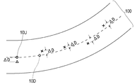
- FIG. Explanatory drawing which shows deviation (DELTA) D of the own vehicle position with respect to a travel route in Example 1.
- FIG. FIG. 3 is a flowchart for explaining a gyro sensor calibration method according to the first embodiment.
- FIG. FIG. 6 is a flowchart for explaining a gyro sensor calibration method according to a third embodiment.
- Example 1 This example is an example in which the marker system 1 that specifies the own vehicle position (vehicle position) with high accuracy is combined with the automatic driving system 6.
- the marker system 1 of the present example has one of technical features in that it has a function of calibrating the gyro sensor using the magnetic marker 10. According to this marker system 1, the accuracy of inertial navigation can be maintained high.
- FIGS. 1 The contents will be described with reference to FIGS.
- the marker system 1 includes a measurement unit 2 that performs magnetic detection and the like, a tag reader 34 that is an example of a position information acquisition unit that acquires marker information indicating the laying position of the magnetic marker 10, and the vehicle position. And a control unit 32 that constitutes a positioning unit that executes a calculation process for specifying the position.
- the automatic driving system 6 (FIG. 2) combined with the marker system 1 includes a vehicle ECU 61 that executes automatic driving control, and a map database (map DB) 65 that stores detailed three-dimensional map data (3D map data). It is configured to include.
- the vehicle ECU 61 causes the vehicle 5 to automatically travel by controlling a steering steering unit, an engine throttle, a brake, etc. (not shown) using the own vehicle position specified by the marker system 1 as a control input value. In FIG. 1, the automatic driving system 6 is not shown.
- the magnetic marker 10 is a road marker laid on the road surface 100 ⁇ / b> S of the road on which the vehicle 5 travels.
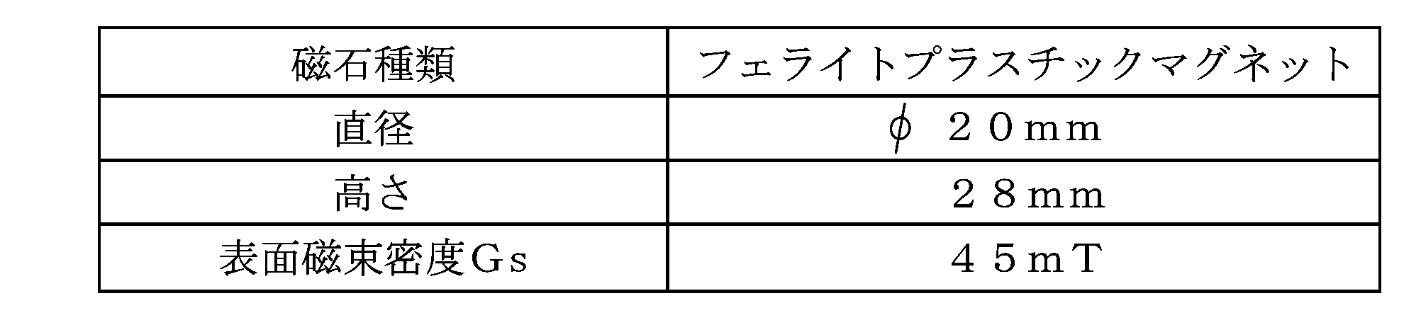
- the magnetic marker 10 has a columnar shape with a diameter of 20 mm and a height of 28 mm.
- the magnetic marker 10 is laid while being accommodated in a hole provided in the road surface 100S.
- the magnetic marker 10 acts on magnetism having a magnetic flux density of 8 ⁇ T (micro Tesla) at an upper limit of 250 mm, which is an upper limit of a range of 100 to 250 mm assumed as a mounting height of the measurement unit 2. Further, in the magnetic marker 10, the surface magnetic flux density Gs representing the magnetic strength on the surface is 45 mT.
- the installation locations 10F of the magnetic markers 10 are provided along the center of the lane 100 divided by left and right lane marks, for example, at intervals of 10 m.
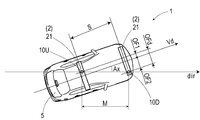
- two magnetic markers 10U ⁇ D are arranged at intervals of 2 m along the direction along the center of the lane 100 (the direction of the road).
- the 2 m interval between the magnetic markers 10U and D is referred to as a marker span M.
- the direction of the line segment connecting the two magnetic markers 10U ⁇ D is referred to as an orientation dir.
- the vehicle direction (vehicle direction) can be specified based on the direction dir, and the gyro sensor 223 can be calibrated.
- the magnetic marker 10U on the upstream side of the road that is opposite to the traveling direction is used for specifying the vehicle position.
- This upstream magnetic marker 10U is provided with an RFID (Radio Frequency IDentification) tag 15 which is a wireless tag for outputting information wirelessly (see FIG. 3).
- RFID Radio Frequency IDentification
- the RFID tag 15 operates by wireless external power feeding and transmits marker information related to the magnetic marker 10U.
- the marker information includes position data indicating the laying position of the corresponding magnetic marker 10U, direction data indicating the direction dir (FIG. 4) (an example of marker direction information that can specify the direction dir), and the like.
- the magnetic marker 10D located on the downstream side is a magnetic marker that determines the direction dir, and the RFID tag 15 is not attached thereto.
- the magnet of the magnetic marker 10 is obtained by dispersing iron oxide magnetic powder in a polymer material.
- This magnet has low electrical conductivity and is unlikely to generate eddy currents or the like during wireless power feeding. Therefore, the RFID tag 15 attached to the magnetic marker 10 can efficiently receive the wirelessly transmitted power.
- An RFID tag 15 that is an example of an information providing unit is an electronic component in which an IC chip 157 is mounted on the surface of a tag sheet 150 (FIG. 5) cut out from, for example, a PET (Polyethylene terephthalate) film.
- a PET Polyethylene terephthalate
- On the surface of the tag sheet 150 print patterns of the loop coil 151 and the antenna 153 are provided.
- the loop coil 151 is a power receiving coil that generates an exciting current by electromagnetic induction from the outside.
- the antenna 153 is a transmission antenna for wirelessly transmitting marker information.
- the RFID tag 15 is disposed on the surface of the magnetic marker 10U on the road surface 100S side.
- the measurement unit 2 is a unit in which a sensor array 21 that is a magnetic detection unit and an IMU (Inertial Measurement Unit) 22 that is an example of a relative position estimation unit are integrated.
- the measuring unit 2 having an elongated bar shape is attached to, for example, the inside of the front bumper in a state of facing the road surface 100S.
- the mounting height of the measurement unit 2 with reference to the road surface 100S is 200 mm.
- the sensor array 21 of the measurement unit 2 includes 15 magnetic sensors Cn (n is an integer of 1 to 15) arranged on a straight line, and a detection processing circuit 212 incorporating a CPU or the like (not shown).
- 15 magnetic sensors Cn are arranged at equal intervals of 10 cm.
- the measurement unit 2 is attached to the vehicle 5 so that the arrangement direction of the magnetic sensors Cn in the sensor array 21 matches the vehicle width direction.
- the magnetic sensor Cn is a sensor that detects magnetism using a known MI effect (Magneto Impedance Effect) that the impedance of a magnetic sensitive body such as an amorphous wire changes sensitively according to an external magnetic field.
- a magnetic sensitive body such as an amorphous wire is disposed along two orthogonal axes so that magnetism acting in the two orthogonal axes can be detected.
- the magnetic sensor Cn is incorporated in the sensor array 21 so that magnetic components in the traveling direction and the vehicle width direction can be detected.
- the magnetic sensor Cn is a highly sensitive sensor having a magnetic flux density measurement range of ⁇ 0.6 mT and a magnetic flux resolution within the measurement range of 0.02 ⁇ T.
- the period of the magnetic measurement by each magnetic sensor Cn of the measurement unit 2 is set to 3 kHz so that the vehicle 5 can cope with high speed travel.
- Table 2 shows a part of the specifications of the magnetic sensor Cn.
- the magnetic marker 10 can act with magnetism having a magnetic flux density of 8 ⁇ T or more in the range of 100 to 250 mm assumed as the mounting height of the magnetic sensor Cn.
- the magnetic marker 10 that acts on magnetism having a magnetic flux density of 8 ⁇ T or more can be detected with high reliability by using the magnetic sensor Cn having a magnetic flux resolution of 0.02 ⁇ T.
- the detection processing circuit 212 (FIG. 2) of the sensor array 21 is an arithmetic circuit that executes marker detection processing for detecting the magnetic marker 10 and the like.
- the detection processing circuit 212 is configured using a CPU (central processing unit) that executes various operations, a memory element such as a ROM (read only memory) and a RAM (random access memory).
- the detection processing circuit 212 acquires the sensor signal output by each magnetic sensor Cn at a cycle of 3 kHz and executes marker detection processing. Then, the detection result of the marker detection process is input to the control unit 32. As will be described in detail later, in this marker detection process, in addition to the detection of the magnetic marker 10, a lateral deviation amount detection process for measuring the lateral deviation amount of the vehicle 5 with respect to the detected magnetic marker 10 is performed.
- the IMU 22 (FIG. 2) incorporated in the measurement unit 2 is an inertial navigation unit that estimates the relative position of the vehicle 5 by inertial navigation.
- the IMU 22 includes a magnetic sensor 221 that is an electronic compass that measures azimuth, an acceleration sensor 222 that measures acceleration, and a gyro sensor 223 that measures angular velocity.
- the gyro sensor 223 is attached to the vehicle 5 so as to measure the angular velocity in the rotational direction around the vertical axis. If the angular velocity measured by the gyro sensor 223 is combined with the direction measured by the magnetic sensor 221, the direction of the vehicle 5 can be estimated with high accuracy.
- the IMU 22 calculates the displacement amount by second-order integration of acceleration, and calculates the relative position with respect to the reference position by integrating the displacement amount along the direction of the vehicle 5. If the relative position estimated by the IMU 22 is used, the position of the host vehicle can be estimated even when the vehicle 5 is positioned between the adjacent magnetic markers 10U.
- the tag reader 34 is a communication unit that wirelessly communicates with the RFID tag 15 disposed on the surface of the magnetic marker 10U.
- the tag reader 34 wirelessly transmits power necessary for the operation of the RFID tag 15 and receives marker information transmitted by the RFID tag 15.
- the marker information includes position data representing the laying position (absolute position) of the corresponding magnetic marker 10U, azimuth data representing the azimuth direction dir connecting the magnetic markers 10U and D at the laying location 10F, and the like.
- the control unit 32 is a unit that controls the measurement unit 2 and the tag reader 34 and specifies the vehicle position, which is the position of the vehicle 5, in real time.
- the control unit 32 inputs the vehicle position to the vehicle ECU 61 that constitutes the automatic driving system 6 of the vehicle 5.
- the control unit 32 includes an electronic board (not shown) on which a CPU that executes various operations, a memory element such as a ROM and a RAM, and the like are mounted.
- the method by which the control unit 32 identifies the position of the vehicle is different between when the vehicle 5 reaches the magnetic marker 10U to which the RFID tag 15 is attached and when the vehicle 5 is positioned between the adjacent magnetic markers 10U. doing.
- the control unit 32 specifies the vehicle position using the marker information received from the RFID tag 15 attached to the magnetic marker 10U.
- the vehicle position is specified based on the relative position of the vehicle 5 estimated by inertial navigation.
- the marker detection process is a process executed by the sensor array 21 of the measurement unit 2. As described above, the sensor array 21 uses the magnetic sensor Cn to execute marker detection processing at a cycle of 3 kHz.
- the magnetic sensor Cn is configured to measure the magnetic components in the traveling direction and the vehicle width direction of the vehicle 5. For example, when the magnetic sensor Cn moves in the traveling direction and passes directly above the magnetic marker 10, the magnetic measurement value in the traveling direction is reversed between positive and negative before and after the magnetic marker 10 as shown in FIG. It changes so as to cross zero at a position just above 10. Accordingly, when the vehicle 5 is traveling, when the zero cross Zc in which the polarity of the traveling direction magnetism detected by any of the magnetic sensors Cn is reversed occurs, it is determined that the measuring unit 2 is located immediately above the magnetic marker 10. it can.
- the detection processing circuit 212 determines that the magnetic marker 10 has been detected when the measurement unit 2 is positioned directly above the magnetic marker 10 and a zero crossing of the magnetic measurement value in the traveling direction has occurred.
- the magnetic measurement value in the vehicle width direction is obtained from the magnetic marker 10.
- the sign is reversed on both sides of the sandwich, and changes so as to cross zero at a position directly above the magnetic marker 10.
- the sign of the magnetism in the vehicle width direction detected by the magnetic sensor Cn differs depending on which side the magnetic sensor Cn is located through.
- FIG. 7 is a diagram showing a distribution of magnetic measurement values in the vehicle width direction of each magnetic sensor Cn of the measurement unit 2. Based on the distribution in the figure, the middle position of two adjacent magnetic sensors Cn across the zero cross Zc where the polarity of the magnetism in the vehicle width direction is reversed, or the magnetism in the vehicle width direction to be detected is zero and both outer sides The position immediately below the magnetic sensor Cn where the sign of the magnetic sensor Cn is reversed is the position of the magnetic marker 10 in the vehicle width direction.
- the detection processing circuit 212 measures the deviation of the position in the vehicle width direction of the magnetic marker 10 with respect to the center position of the measurement unit 2 (position of the magnetic sensor C8) as the above-described lateral deviation amount (lateral deviation amount detection processing).
- the position of the zero cross Zc is a position corresponding to C9.5 in the middle of C9 and C10.
- the lateral displacement amount of the magnetic marker 10 is (9.5-8) ⁇ 10 cm with reference to C8 located at the center of the measurement unit 2 in the vehicle width direction. It becomes.
- the vehicle ECU 61 of the automatic driving system 6 reads out the corresponding data from the map DB 65 storing the 3D map data and becomes a detailed route that becomes a control target of the automatic driving.
- Data is set (S102).
- the route data is data including a series of points represented by at least absolute position data, for example, as indicated by a broken line in FIG.
- the control unit 32 of the marker system 1 repeatedly executes the marker detection process by the sensor array 21 (S201).
- the control unit 32 controls the tag reader 34 to receive the marker information output from the RFID tag 15 ( S223).
- the control unit 32 uses the position of the magnetic marker 10U represented by the position data included in the marker information as a reference, and the position offset by the amount of lateral deviation measured by the measurement unit 2 in the marker detection process is the vehicle position ( 9) (S204).
- the magnetic marker 10 detected by the sensor array 21 is the upstream magnetic marker 10U or the downstream magnetic marker 10D of the laying position is determined based on the RFID that received the previous position data (marker information). What is necessary is just to determine by the distance etc. from the laying position of the magnetic marker 10U with the tag 15.
- the IMU 22 incorporated in the measurement unit 2 has the most recently detected magnetic marker 10U.
- the relative position of the vehicle 5 is estimated by inertial navigation using the own vehicle position specified based on the laying position (the position indicated by ⁇ in FIG. 9) as a reference position. Specifically, as described above, the IMU 22 calculates the displacement amount by the second order integration of the measured acceleration. And IMU22 estimates the relative position of the vehicle 5 with respect to said reference position by integrating
- the vehicle position specified by the marker system 1 (the positions indicated by ⁇ and X in FIG. 9) is input to the vehicle ECU 61 of the automatic driving system 6.
- the vehicle ECU 61 calculates a deviation ⁇ D with respect to the route data of the control target value indicated by the broken line in FIG. 10 (S103).
- the vehicle ECU 61 executes vehicle control such as steering control and throttle control based on the deviation ⁇ D (S104) to realize automatic travel.
- the vehicle orientation Vd that is the orientation of the vehicle 5 can be specified with respect to the orientation dir at each installation location 10 ⁇ / b> F.
- the gyro sensor 223 can be calibrated using the vehicle orientation Vd at the two laying points (points) 10F. The flow of this calibration method will be described with reference to the flowchart of FIG.
- the control unit 32 In the state where the vehicle 5 is traveling, the control unit 32 repeatedly executes the marker detection process P1 including the lateral deviation detection process by controlling the sensor array 21 (S301: NO). When the vehicle 5 reaches the first installation location 10F and the upstream magnetic marker 10U is detected (S301: YES), the control unit 32 controls the tag reader 34 to store the RFID tag 15. The marker information is read (S302).
- control unit 32 controls the sensor array 21 to restart the marker detection process P1.
- the control unit 32 repeatedly executes the marker detection process P1 until the downstream magnetic marker 10D is detected (S303: NO).
- the control unit 32 uses the lateral shift amounts OF1 and OF2 (FIG. 12) respectively measured for the magnetic markers 10U and D by the marker detection process P1.
- the vehicle orientation Vd is calculated (S304, orientation estimation processing).
- the vehicle orientation calculated at the first installation location 10F is Vd (1)
- vehicle orientation corresponding to the second installation location 10F is Vd (2).
- the control unit 32 calculates the deviation angle Ax of the vehicle azimuth (traveling direction) Vd with respect to the direction dir based on the lateral deviation amounts OF1 and OF2 with respect to the two magnetic markers 10U and D.
- the direction dir is an absolute direction represented by the direction data included in the marker information.
- the vehicle orientation Vd can be specified as an orientation shifted in the yaw direction (rotation direction around the vertical axis) by the deviation angle Ax with reference to the orientation dir.
- control unit 32 starts the temporal integration process of the angular velocity that is the measurement value of the gyro sensor 223 in response to the detection of the magnetic sensor 10D on the downstream side of the first installation site 10F (S305, integration process). ).
- This integration process is an arithmetic process for obtaining a measurement rotation angle that is a rotation angle in the yaw direction while passing through the two laying points 10F.
- the control unit 32 continues this integration process until the magnetic marker 10D on the downstream side of the second installation location 10F is detected.
- the control unit 32 controls the sensor array 21 to restart the marker detection process P1.
- This marker detection process P1 is repeatedly executed until the magnetic marker 10 at the second installation location 10F is detected (S306: NO).
- the control unit 32 When the magnetic marker 10U located upstream of the second laying place 10F is detected (S306: YES), the control unit 32 reads the marker information from the RFID tag 15 by controlling the tag reader 34. (S307). Further, the control unit 32 repeatedly executes the marker detection process P1 by controlling the sensor array 21 so that the downstream magnetic marker 10D can be detected (S308: NO). When the magnetic marker 10D located on the downstream side of the laying place 10F can be detected (S308: YES), the control unit 32 similarly detects the lateral displacement amounts OF1, OF2 (FIG. 2) with respect to the two magnetic markers 10U ⁇ D. 12), the vehicle orientation Vd (2) is calculated (S309, orientation estimation processing).
- the control unit 32 calculates the difference between the vehicle orientations Vd (1) and Vd (2) (the amount of change in the vehicle orientation) calculated and specified by the vehicle 5 at any two installation locations 10F as the vehicle rotation angle ( S310, difference calculation processing). In addition, the control unit 32 ends the temporal integration process of the angular velocity measured by the gyro sensor 223, and calculates a measured rotation angle (rotation angle) that is an integrated value (S311, integration process). Then, the control unit 32 compares the vehicle rotation angle with the measured rotation angle (S312), and performs the calibration process P2 of the gyro sensor 223.
- the content of the calibration process P2 of the gyro sensor 223 will be described. If the rotation in the yaw direction is zero (zero point), ideally, the angular velocity measured by the gyro sensor 223 should be zero (deg / sec). However, the zero point of the gyro sensor 223 may shift due to the influence of a change over time, a temperature change, or the like, and the angular velocity output from the gyro sensor 223 at the zero point often does not become zero. This zero point deviation amount is manifested as an integration constant when the angular velocity is integrated over time.
- the deviation amount of the zero point by finding an integral constant such that the difference between the vehicle rotation angle and the measured rotation angle is close to zero (the difference is small).
- the deviation amount of the zero point it is preferable to uniformly offset the measurement value so that the deviation amount can be offset with respect to the measurement value (angular velocity) output from the gyro sensor 223. If the gyro sensor 223 is calibrated in this way, the accuracy of the angular velocity output from the gyro sensor 223 can be improved. For example, a value obtained by dividing the difference between the vehicle rotation angle and the measured rotation angle by the integration interval (number of integrations) can be handled as the zero point deviation amount.
- the moving distance D of the vehicle 5 required to pass the two magnetic markers 10 in the marker span M can be calculated, and the vehicle speed can be calculated with high accuracy.
- the timing at which the upstream magnetic marker 10U is detected is t1
- the timing at which the downstream magnetic marker 10D is detected is t2.
- an error in the speed (vehicle speed) obtained by integrating the measured acceleration by the IMU 22 can be specified. If the vehicle speed error can be specified in this way, the acceleration sensor 222 that measures acceleration can be calibrated.
- the marker system 1 of the present example is a system that uses the magnetic marker 10 to identify the vehicle position. Since this marker system 1 does not presuppose reception of GPS radio waves or the like, position accuracy does not become unstable even in places where GPS radio waves cannot be received or become unstable, such as tunnels and valleys of buildings. . According to the marker system 1, highly accurate driving support control can be realized regardless of the environment.
- this marker system 1 it is necessary to maintain high accuracy of the IMU 22 that realizes inertial navigation so that the vehicle position can be specified with high accuracy.
- sensors such as the gyro sensor 223 and the acceleration sensor 222, there is a possibility that a measured value may be shifted according to a change with time, a temperature change, or the like, and therefore it is necessary to calibrate appropriately at any time.
- the gyro sensor 223, the acceleration sensor 222, etc. can be calibrated using the magnetic marker 10 laid on the road.
- the vehicle direction Vd in the yaw direction can be specified with high accuracy.
- the gyro sensor 223 that measures the angular velocity in the yaw direction can be calibrated with high certainty.
- the vehicle speed V can be specified with high accuracy by using the two magnetic markers 10U ⁇ D arranged with an interval of the marker span M of 2 m at the installation location 10F. If the vehicle speed V with high accuracy is used, it is possible to calibrate the acceleration sensor 222 that measures acceleration serving as original data for calculating the vehicle speed based on second-order integration.
- the calibration method of this example is based on the premise that the change in the steering angle is sufficiently small when passing through the installation location 10F.
- the calibration process P2 of the gyro sensor 223 may be canceled.
- This example shows a configuration example in which the RFID tag 15 attached to the magnetic marker 10U transmits marker information including position data and orientation data.
- a marker database that can be referred to using the tag ID transmitted by the RFID tag 15 may be employed.
- position data representing the laying position of at least one of the two magnetic markers 10U ⁇ D of the laying place 10F and the absolute direction dir of a line segment connecting the two magnetic markers 10U ⁇ D are represented. It is preferable to record the azimuth data or the like by linking the tag ID.
- the marker database may be provided in a server device with which the vehicle 5 can communicate, or may be provided in a storage area of the vehicle 5.
- the configuration example in which two magnetic markers 10 are arranged at each laying place 10F is shown, but three or more magnetic markers 10 may be arranged linearly.
- a plurality of magnetic markers 10 may be arranged along a reference direction such as a north-south direction or an east-west direction.
- the L-shaped vertical line and horizontal line may be aligned with the north-south and east-west directions, respectively.
- the magnetic marker 10 is arranged along the direction of the north-south direction and the east-west direction that is close to the direction parallel to the road direction.
- the direction of the magnetic marker 10 can be distinguished by the magnetic polarity. May be.
- the N pole-N pole may represent the north-south direction
- the S pole-S pole may represent the east-west direction.
- Example 2 This example is an example of the marker system 1 in which the method for specifying the vehicle orientation Vd is changed based on the first embodiment. This example is different from Example 1 in that the sensor array 21 is arranged at a distance of 2 m before and after the vehicle 5. The method for specifying the vehicle orientation Vd is different from that in the first embodiment due to such a difference in the arrangement of the sensor array 21.
- the contents will be described with reference to FIG. 2 to 4 used in the description of the first embodiment are also referred to as appropriate.
- the arrangement interval (sensor span S) of the sensor array 21 in the vehicle 5 and the arrangement interval (marker span M) of the magnetic marker 10 in the laying place 10 ⁇ / b> F match. Yes. Therefore, when the vehicle 5 passes through the installation location 10F, the front and rear sensor arrays 21 can detect the two magnetic markers 10U ⁇ D almost simultaneously.
- the vehicle orientation Vd is calculated based on the lateral displacements OF1 and OF2 measured by the front and rear sensor arrays 21 with respect to the magnetic markers 10U ⁇ D.
- the deviation angle Ax of the vehicle azimuth (traveling direction) with respect to the azimuth direction dir connecting the two magnetic markers 10U and D can be calculated by the following equation.
- the vehicle orientation Vd can be specified as an orientation shifted in the yaw direction by the shift angle Ax with respect to the orientation dir.
- Example 3 the content of the calibration process of the gyro sensor 223 is changed based on the configuration of the first embodiment.
- the contents will be described with reference to FIG. 2 to 4 used in the description of the first embodiment are also referred to as appropriate.
- the calibration process of the gyro sensor 223 of this example can be executed only for the laying place 10F provided on a flat straight road having a change in gradient of less than 0.01% and a radius of curvature of 3000 m or more, for example. .
- the marker information transmitted by the RFID tag 15 attached to the upstream magnetic marker 10U disposed at the laying place 10F includes the above flat straight road in addition to the position data and direction data similar to those in the first embodiment. Thus, information indicating that the calibration processing of this example can be executed is included.
- the control unit 32 included in the vehicle 5 repeatedly executes the marker detection process P1 by controlling the sensor array 21 (S401: NO).
- the control unit 32 reads the marker information from the RFID tag 15 by controlling the tag reader 34 (S402). Then, the control unit 32 determines whether or not information indicating that the calibration process can be performed is included in the marker information (S403).
- the control unit 32 controls the sensor array 21 so that the magnetic marker 10D adjacent to the downstream side can be detected. Then, the marker detection process P1 is resumed.
- the control unit 32 calculates a difference value of the lateral deviation amount with respect to the magnetic marker 10U ⁇ D (S405).
- the control unit 32 determines the deviation angle of the direction of the vehicle 5 with respect to the straight road direction (Ax in FIG. 12). It is judged that the vehicle goes straight ahead.) And when it is judged that the vehicle 5 is in a straight line state, the calibration process P2 of the gyro sensor 223 is performed. In this calibration process P2, the gyro sensor 223 is calibrated so that the angular velocity, which is the measurement value of the gyro sensor 223, becomes zero.
- a predetermined threshold for example, 5 cm
- the marker information output from the RFID tag 15 includes information indicating that the calibration process can be executed.
- the laying location where the calibration process can be performed may be different from other laying locations, such as the number of magnetic markers 10 arranged.
- the gyro sensor 223 can be calibrated even at a location where the magnetic marker 10 with the RFID tag 15 is not laid.
- the deviation angle may be obtained by calculation using the deviation angle Ax expression shown in the first embodiment. In this case, it is preferable to execute a threshold value determination regarding the deviation angle. Other configurations and operational effects are the same as those in the first embodiment.
Landscapes
- Engineering & Computer Science (AREA)
- Radar, Positioning & Navigation (AREA)
- Remote Sensing (AREA)
- Physics & Mathematics (AREA)
- General Physics & Mathematics (AREA)
- Automation & Control Theory (AREA)
- Manufacturing & Machinery (AREA)
- Aviation & Aerospace Engineering (AREA)
- Electromagnetism (AREA)
- Navigation (AREA)
- Gyroscopes (AREA)
- Traffic Control Systems (AREA)
- Control Of Position, Course, Altitude, Or Attitude Of Moving Bodies (AREA)
Abstract
Description
道路に敷設された磁気マーカに対する車両の横ずれ量を検出する横ずれ量検出処理と、
少なくとも2個の磁気マーカが敷設された敷設箇所を車両が通過する際、当該少なくとも2個の磁気マーカについて前記横ずれ量検出処理が検出した横ずれ量を入力値とする演算処理により車両の方位を推定する方位推定処理と、
該方位推定処理により推定された車両の方位を利用してジャイロセンサを較正する較正処理と、を実施するジャイロセンサの較正方法にある。
(実施例1)
本例は、高精度に自車位置(車両の位置)を特定するマーカシステム1を自動運転システム6に組み合わせた例である。特に、本例のマーカシステム1は、磁気マーカ10を利用してジャイロセンサを較正する機能を有する点に技術的特徴のひとつを有している。このマーカシステム1によれば、慣性航法の精度を高く維持可能である。この内容について、図1~図12を用いて説明する。
計測ユニット2は、図1及び図2のごとく、磁気検出部であるセンサアレイ21と、相対位置推定部の一例であるIMU(Inertial Measurement Unit)22と、が一体化されたユニットである。細長い棒状をなす計測ユニット2は、路面100Sと対面する状態で、例えばフロントバンパーの内側等に取り付けられる。本例の車両5の場合、路面100Sを基準とした計測ユニット2の取付け高さが200mmとなっている。

(1)マーカ検出処理
マーカ検出処理は、計測ユニット2のセンサアレイ21が実行する処理である。センサアレイ21は、上記の通り、磁気センサCnを用いて3kHzの周期でマーカ検出処理を実行する。
次に、図8~図10を参照してマーカシステム1と自動運転システム6とを備える車両5の全体動作について説明する。
自動運転システム6において走行ルートが設定されると(S101)、自動運転システム6の車両ECU61は、3Dマップデータを記憶する地図DB65から対応するデータを読み出して自動運転の制御目標となる詳細なルートデータを設定する(S102)。ルートデータは、例えば図9中の破線で示すように、少なくとも絶対位置のデータで表される地点の連なりを含むデータである。
上記のごとく本例のマーカシステム1では、磁気マーカ10の各敷設箇所10Fにおいて、マーカスパンM=2mの間隔で2個の磁気マーカ10U・Dが配置されている(図4参照。)。2個の磁気マーカ10U・Dを結ぶ線分の方位dirは、車線100の中央に沿う方向、すなわち道路の方向に一致している。敷設箇所10Fの上流側の磁気マーカ10Uに付設されたRFIDタグ15は、この方位dirを表す方位データ(マーカ情報)を出力(無線送信)する。
ずれ角 Ax=arcsin(OFd/M)
ここで、横ずれ量OF1、OF2は、車両5の幅方向中央を境に正または負の値となるよう定義される。
移動距離 D=M×cosAx
車速 V=D/(t2-t1)
2個の磁気マーカ10を道路の方向に沿って配置した本例の構成に代えて、南北方向や東西方向など基準方向に沿って複数の磁気マーカ10を配置しても良い。図12のように車両方位を特定する際、車両方位Vdに対して2個の磁気マーカ10を結ぶ方位dirが直角に近づくと、横ずれ量の計測が難しくなり車両方位Vdの演算精度が低下する傾向にある。そこで、車両方位Vdの演算に利用する磁気マーカ10の配置方向を選択できるよう、L字状に3個の磁気マーカ10を配置することも良い。L字状の縦の線、横の線をそれぞれ、南北、東西の方向に一致させると良い。
本例は、実施例1に基づいて、車両方位Vdの特定方法を変更したマーカシステム1の例である。本例は、車両5の前後に2mの間隔をあけてセンサアレイ21が配置されている点において、実施例1とは相違している。そして、このようなセンサアレイ21の配置の相違により、車両方位Vdの特定方法が実施例1とは相違している。この内容について図13を参照して説明する。なお、実施例1の説明に用いた図2~図4も適宜、参照する。
ずれ角 Ax=arcsin(OFd/M)
なお、その他の構成及び作用効果については実施例1と同様である。
本例は、実施例1の構成に基づいて、ジャイロセンサ223の較正処理の内容を変更した例である。この内容について、図14を参照して説明する。なお、実施例1の説明に用いた図2~図4も適宜、参照する。
本例のジャイロセンサ223の較正処理は、例えば勾配の変化が0.01%未満であって、曲率半径が3000m以上の平坦な直線の道路に設けられた敷設箇所10Fに限って実行可能である。この敷設箇所10Fに配置された上流側の磁気マーカ10Uに付設されたRFIDタグ15が送信するマーカ情報には、実施例1と同様の位置データや方位データに加えて、上記の平坦な直線道路であって本例の較正処理を実行可能である旨の情報が含まれている。
車両5が走行中の状態において、車両5が備える制御ユニット32は、センサアレイ21を制御することでマーカ検出処理P1を繰り返し実行する(S401:NO)。敷設箇所10Fの上流側の磁気マーカ10Uが検出されたとき(S401:YES)、制御ユニット32は、タグリーダ34を制御することで、RFIDタグ15からのマーカ情報の読取を実行する(S402)。そして、制御ユニット32は、較正処理を実行可能である旨の情報がマーカ情報に含まれているか否かを判断する(S403)。
なお、その他の構成及び作用効果については実施例1と同様である。
10 磁気マーカ
15 RFIDタグ(情報提供部、無線タグ)
2 計測ユニット
21 センサアレイ(磁気検出部)
212 検出処理回路
22 IMU
222 加速度センサ
223 ジャイロセンサ
32 制御ユニット
34 タグリーダ
5 車両
6 自動運転システム
61 車両ECU
65 地図データベース(地図DB)
Claims (5)
- 鉛直方向の軸回りに生じる回転方向の角速度を計測するジャイロセンサを備える車両における当該ジャイロセンサの較正方法であって、
道路に敷設された磁気マーカに対する車両の横ずれ量を検出する横ずれ量検出処理と、
少なくとも2個の磁気マーカが敷設された敷設箇所を車両が通過する際、当該少なくとも2個の磁気マーカについて前記横ずれ量検出処理が検出した横ずれ量を入力値とする演算処理により車両の方位を推定する方位推定処理と、
該方位推定処理により推定された車両の方位を利用してジャイロセンサを較正する較正処理と、を実施するジャイロセンサの較正方法。 - 請求項1において、道路に沿って離れた2箇所の前記敷設箇所を車両が通過する間の前記ジャイロセンサの計測値を時間的に積分する積分処理を実施し、
前記較正処理では、前記2箇所の敷設箇所において前記方位推定処理で推定された車両の方位の差分である車両回転角と、前記積分処理による積分値である計測回転角と、の差分が小さくなるようにジャイロセンサを較正するジャイロセンサの較正方法。 - 請求項1において、前記較正処理は、直線の道路に設けられた敷設箇所を通過する際に前記方位推定処理が推定する車両の方位について、当該直線の道路の方向に対するずれ角が十分小さいとき、前記ジャイロセンサが計測する角速度の値をゼロに近づける処理であるジャイロセンサの較正方法。
- 請求項1~3のいずれか1項において、前記敷設箇所に配置された磁気マーカの少なくともいずれかには、当該敷設箇所に配置された前記少なくとも2個の磁気マーカを結ぶ線分の方向を特定可能なマーカ方位情報を提供する情報提供部が付設されているジャイロセンサの較正方法。
- 請求項4において、前記情報提供部は、前記磁気マーカに取り付けられた無線タグであるジャイロセンサの較正方法。
Priority Applications (4)
| Application Number | Priority Date | Filing Date | Title |
|---|---|---|---|
| US17/059,228 US11454516B2 (en) | 2018-06-04 | 2019-05-17 | Gyro sensor calibration method |
| SG11202011828WA SG11202011828WA (en) | 2018-06-04 | 2019-05-17 | Gyro sensor calibration method |
| EP19814551.8A EP3805698B1 (en) | 2018-06-04 | 2019-05-17 | Gyro sensor calibration method |
| CN201980035885.XA CN112204352B (zh) | 2018-06-04 | 2019-05-17 | 陀螺仪传感器的校正方法 |
Applications Claiming Priority (2)
| Application Number | Priority Date | Filing Date | Title |
|---|---|---|---|
| JP2018106836A JP7147275B2 (ja) | 2018-06-04 | 2018-06-04 | ジャイロセンサの較正方法 |
| JP2018-106836 | 2018-06-04 |
Publications (1)
| Publication Number | Publication Date |
|---|---|
| WO2019235188A1 true WO2019235188A1 (ja) | 2019-12-12 |
Family
ID=68770450
Family Applications (1)
| Application Number | Title | Priority Date | Filing Date |
|---|---|---|---|
| PCT/JP2019/019802 Ceased WO2019235188A1 (ja) | 2018-06-04 | 2019-05-17 | ジャイロセンサの較正方法 |
Country Status (6)
| Country | Link |
|---|---|
| US (1) | US11454516B2 (ja) |
| EP (1) | EP3805698B1 (ja) |
| JP (1) | JP7147275B2 (ja) |
| CN (1) | CN112204352B (ja) |
| SG (1) | SG11202011828WA (ja) |
| WO (1) | WO2019235188A1 (ja) |
Cited By (2)
| Publication number | Priority date | Publication date | Assignee | Title |
|---|---|---|---|---|
| WO2022056899A1 (zh) * | 2020-09-21 | 2022-03-24 | 华为技术有限公司 | 车辆测速装置的故障诊断方法和故障诊断装置 |
| JPWO2022154103A1 (ja) * | 2021-01-18 | 2022-07-21 |
Families Citing this family (6)
| Publication number | Priority date | Publication date | Assignee | Title |
|---|---|---|---|---|
| JP6928307B2 (ja) * | 2017-03-28 | 2021-09-01 | 愛知製鋼株式会社 | マーカ検出システム及びマーカ検出方法 |
| JP6965815B2 (ja) * | 2018-04-12 | 2021-11-10 | 愛知製鋼株式会社 | マーカ検出システム、及びマーカ検出システムの運用方法 |
| US11604476B1 (en) * | 2018-10-05 | 2023-03-14 | Glydways Inc. | Road-based vehicle guidance system |
| JP7817593B2 (ja) * | 2021-05-12 | 2026-02-19 | 愛知製鋼株式会社 | センサユニット、システム及び磁気マーカの検出方法 |
| JP7518390B2 (ja) | 2021-05-12 | 2024-07-18 | 愛知製鋼株式会社 | システム及び磁気マーカの検出方法 |
| CN113790737B (zh) * | 2021-08-12 | 2024-02-02 | 北京航空航天大学 | 一种阵列式传感器的现场快速标定方法 |
Citations (5)
| Publication number | Priority date | Publication date | Assignee | Title |
|---|---|---|---|---|
| JP2000028632A (ja) * | 1998-07-10 | 2000-01-28 | Honda Motor Co Ltd | ヨーレートセンサの補正装置 |
| JP2014215232A (ja) * | 2013-04-26 | 2014-11-17 | トヨタ自動車株式会社 | ヨーレート検出装置 |
| JP2016091412A (ja) | 2014-11-07 | 2016-05-23 | アイシン・エィ・ダブリュ株式会社 | 自動運転支援システム、自動運転支援方法及びコンピュータプログラム |
| WO2017209112A1 (ja) * | 2016-06-03 | 2017-12-07 | 愛知製鋼株式会社 | 位置捕捉方法及びシステム |
| JP2018036797A (ja) * | 2016-08-30 | 2018-03-08 | 愛知製鋼株式会社 | 車両用システム及び進路推定方法 |
Family Cites Families (16)
| Publication number | Priority date | Publication date | Assignee | Title |
|---|---|---|---|---|
| JP2572968B2 (ja) * | 1986-07-14 | 1997-01-16 | 株式会社椿本チエイン | 自律走行車の誘導方法 |
| JPH02247521A (ja) * | 1989-03-20 | 1990-10-03 | Nec Home Electron Ltd | 角速度センサの補正方法 |
| JP2591192B2 (ja) * | 1989-11-02 | 1997-03-19 | 日産自動車株式会社 | 車両用走行方位検出装置 |
| US5281901A (en) * | 1990-12-03 | 1994-01-25 | Eaton-Kenway, Inc. | Downward compatible AGV system and methods |
| JPH0462419A (ja) * | 1990-06-29 | 1992-02-27 | Matsushita Electric Ind Co Ltd | 方位検出装置 |
| JP3645945B2 (ja) * | 1994-08-23 | 2005-05-11 | クラリオン株式会社 | ジャイロのドリフト補正方法及び補正回路 |
| JPH10207540A (ja) * | 1997-01-24 | 1998-08-07 | Toshiba Eng Co Ltd | 無人搬送車 |
| JP2006209567A (ja) | 2005-01-31 | 2006-08-10 | Nippon Sharyo Seizo Kaisha Ltd | 無人搬送車の誘導装置 |
| JP4848931B2 (ja) | 2006-11-13 | 2011-12-28 | 株式会社デンソー | 角速度センサの信号補正装置 |
| JP5445067B2 (ja) | 2009-11-26 | 2014-03-19 | 富士通株式会社 | センサ補正プログラム、センサ補正装置およびセンサ補正方法 |
| JP5390360B2 (ja) | 2009-12-10 | 2014-01-15 | 日本車輌製造株式会社 | 自動搬送車 |
| JP2013145168A (ja) * | 2012-01-13 | 2013-07-25 | Denso Corp | 車載用ジャイロの角速度誤差補正装置 |
| US20150247719A1 (en) | 2014-03-03 | 2015-09-03 | Tomorrow's Transportation Today | Position sensing system for intelligent vehicle guidance |
| CN106403931A (zh) * | 2015-07-31 | 2017-02-15 | 北京航天计量测试技术研究所 | 一种磁地标动态定位方法 |
| CN106249736B (zh) * | 2016-07-13 | 2020-05-08 | 上海交通大学 | 一种基于磁钉地图导航的自动导引车 |
| JP6828314B2 (ja) | 2016-08-30 | 2021-02-10 | 愛知製鋼株式会社 | 車両用の学習システム及び学習方法 |
-
2018
- 2018-06-04 JP JP2018106836A patent/JP7147275B2/ja active Active
-
2019
- 2019-05-17 SG SG11202011828WA patent/SG11202011828WA/en unknown
- 2019-05-17 EP EP19814551.8A patent/EP3805698B1/en active Active
- 2019-05-17 WO PCT/JP2019/019802 patent/WO2019235188A1/ja not_active Ceased
- 2019-05-17 US US17/059,228 patent/US11454516B2/en active Active
- 2019-05-17 CN CN201980035885.XA patent/CN112204352B/zh active Active
Patent Citations (5)
| Publication number | Priority date | Publication date | Assignee | Title |
|---|---|---|---|---|
| JP2000028632A (ja) * | 1998-07-10 | 2000-01-28 | Honda Motor Co Ltd | ヨーレートセンサの補正装置 |
| JP2014215232A (ja) * | 2013-04-26 | 2014-11-17 | トヨタ自動車株式会社 | ヨーレート検出装置 |
| JP2016091412A (ja) | 2014-11-07 | 2016-05-23 | アイシン・エィ・ダブリュ株式会社 | 自動運転支援システム、自動運転支援方法及びコンピュータプログラム |
| WO2017209112A1 (ja) * | 2016-06-03 | 2017-12-07 | 愛知製鋼株式会社 | 位置捕捉方法及びシステム |
| JP2018036797A (ja) * | 2016-08-30 | 2018-03-08 | 愛知製鋼株式会社 | 車両用システム及び進路推定方法 |
Non-Patent Citations (1)
| Title |
|---|
| See also references of EP3805698A4 |
Cited By (3)
| Publication number | Priority date | Publication date | Assignee | Title |
|---|---|---|---|---|
| WO2022056899A1 (zh) * | 2020-09-21 | 2022-03-24 | 华为技术有限公司 | 车辆测速装置的故障诊断方法和故障诊断装置 |
| JPWO2022154103A1 (ja) * | 2021-01-18 | 2022-07-21 | ||
| JP7795112B2 (ja) | 2021-01-18 | 2026-01-07 | 愛知製鋼株式会社 | 制御方法及び制御システム |
Also Published As
| Publication number | Publication date |
|---|---|
| EP3805698B1 (en) | 2025-02-12 |
| US20210215507A1 (en) | 2021-07-15 |
| JP7147275B2 (ja) | 2022-10-05 |
| CN112204352A (zh) | 2021-01-08 |
| SG11202011828WA (en) | 2020-12-30 |
| US11454516B2 (en) | 2022-09-27 |
| JP2019211304A (ja) | 2019-12-12 |
| EP3805698A1 (en) | 2021-04-14 |
| EP3805698A4 (en) | 2022-03-16 |
| CN112204352B (zh) | 2024-03-05 |
Similar Documents
| Publication | Publication Date | Title |
|---|---|---|
| US11906307B2 (en) | Correction method for gyro sensor | |
| CN110419067B (zh) | 标识器系统 | |
| WO2019235188A1 (ja) | ジャイロセンサの較正方法 | |
| US11334087B2 (en) | Magnetic marker installation method and work system | |
| JP6946695B2 (ja) | マーカシステム | |
| US11287263B2 (en) | Position capturing system and position capturing method | |
| WO2018043267A1 (ja) | 車両用の学習システム及び学習方法 | |
| US20250383662A1 (en) | Vehicular system and control method | |
| WO2022270365A1 (ja) | 車両用システム | |
| WO2020175439A1 (ja) | 位置推定方法及び位置推定システム |
Legal Events
| Date | Code | Title | Description |
|---|---|---|---|
| 121 | Ep: the epo has been informed by wipo that ep was designated in this application |
Ref document number: 19814551 Country of ref document: EP Kind code of ref document: A1 |
|
| NENP | Non-entry into the national phase |
Ref country code: DE |
|
| ENP | Entry into the national phase |
Ref document number: 2019814551 Country of ref document: EP Effective date: 20210111 |
|
| WWG | Wipo information: grant in national office |
Ref document number: 11202011828W Country of ref document: SG |
|
| WWP | Wipo information: published in national office |
Ref document number: 11202011828W Country of ref document: SG |