WO2019235277A1 - Dispositif bioadhésif - Google Patents
Dispositif bioadhésif Download PDFInfo
- Publication number
- WO2019235277A1 WO2019235277A1 PCT/JP2019/020818 JP2019020818W WO2019235277A1 WO 2019235277 A1 WO2019235277 A1 WO 2019235277A1 JP 2019020818 W JP2019020818 W JP 2019020818W WO 2019235277 A1 WO2019235277 A1 WO 2019235277A1
- Authority
- WO
- WIPO (PCT)
- Prior art keywords
- exterior body
- wiring board
- switch
- temperature
- temperature sensor
- Prior art date
- Legal status (The legal status is an assumption and is not a legal conclusion. Google has not performed a legal analysis and makes no representation as to the accuracy of the status listed.)
- Ceased
Links
Images





Classifications
-
- G—PHYSICS
- G01—MEASURING; TESTING
- G01K—MEASURING TEMPERATURE; MEASURING QUANTITY OF HEAT; THERMALLY-SENSITIVE ELEMENTS NOT OTHERWISE PROVIDED FOR
- G01K13/00—Thermometers specially adapted for specific purposes
- G01K13/20—Clinical contact thermometers for use with humans or animals
-
- A—HUMAN NECESSITIES
- A61—MEDICAL OR VETERINARY SCIENCE; HYGIENE
- A61B—DIAGNOSIS; SURGERY; IDENTIFICATION
- A61B5/00—Measuring for diagnostic purposes; Identification of persons
- A61B5/68—Arrangements of detecting, measuring or recording means, e.g. sensors, in relation to patient
- A61B5/6801—Arrangements of detecting, measuring or recording means, e.g. sensors, in relation to patient specially adapted to be attached to or worn on the body surface
- A61B5/683—Means for maintaining contact with the body
- A61B5/6832—Means for maintaining contact with the body using adhesives
-
- A—HUMAN NECESSITIES
- A61—MEDICAL OR VETERINARY SCIENCE; HYGIENE
- A61B—DIAGNOSIS; SURGERY; IDENTIFICATION
- A61B5/00—Measuring for diagnostic purposes; Identification of persons
- A61B5/01—Measuring temperature of body parts ; Diagnostic temperature sensing, e.g. for malignant or inflamed tissue
-
- A—HUMAN NECESSITIES
- A61—MEDICAL OR VETERINARY SCIENCE; HYGIENE
- A61B—DIAGNOSIS; SURGERY; IDENTIFICATION
- A61B5/00—Measuring for diagnostic purposes; Identification of persons
- A61B5/68—Arrangements of detecting, measuring or recording means, e.g. sensors, in relation to patient
- A61B5/6801—Arrangements of detecting, measuring or recording means, e.g. sensors, in relation to patient specially adapted to be attached to or worn on the body surface
- A61B5/683—Means for maintaining contact with the body
- A61B5/6832—Means for maintaining contact with the body using adhesives
- A61B5/6833—Adhesive patches
-
- A—HUMAN NECESSITIES
- A61—MEDICAL OR VETERINARY SCIENCE; HYGIENE
- A61B—DIAGNOSIS; SURGERY; IDENTIFICATION
- A61B5/00—Measuring for diagnostic purposes; Identification of persons
- A61B5/74—Details of notification to user or communication with user or patient; User input means
- A61B5/7475—User input or interface means, e.g. keyboard, pointing device, joystick
-
- G—PHYSICS
- G01—MEASURING; TESTING
- G01K—MEASURING TEMPERATURE; MEASURING QUANTITY OF HEAT; THERMALLY-SENSITIVE ELEMENTS NOT OTHERWISE PROVIDED FOR
- G01K1/00—Details of thermometers not specially adapted for particular types of thermometer
- G01K1/14—Supports; Fastening devices; Arrangements for mounting thermometers in particular locations
-
- G—PHYSICS
- G01—MEASURING; TESTING
- G01K—MEASURING TEMPERATURE; MEASURING QUANTITY OF HEAT; THERMALLY-SENSITIVE ELEMENTS NOT OTHERWISE PROVIDED FOR
- G01K7/00—Measuring temperature based on the use of electric or magnetic elements directly sensitive to heat ; Power supply therefor, e.g. using thermoelectric elements
-
- H—ELECTRICITY
- H01—ELECTRIC ELEMENTS
- H01H—ELECTRIC SWITCHES; RELAYS; SELECTORS; EMERGENCY PROTECTIVE DEVICES
- H01H13/00—Switches having rectilinearly-movable operating part or parts adapted for pushing or pulling in one direction only, e.g. push-button switch
- H01H13/02—Details
- H01H13/12—Movable parts; Contacts mounted thereon
- H01H13/14—Operating parts, e.g. push-button
-
- A—HUMAN NECESSITIES
- A61—MEDICAL OR VETERINARY SCIENCE; HYGIENE
- A61B—DIAGNOSIS; SURGERY; IDENTIFICATION
- A61B2562/00—Details of sensors; Constructional details of sensor housings or probes; Accessories for sensors
- A61B2562/02—Details of sensors specially adapted for in-vivo measurements
- A61B2562/0271—Thermal or temperature sensors
-
- A—HUMAN NECESSITIES
- A61—MEDICAL OR VETERINARY SCIENCE; HYGIENE
- A61B—DIAGNOSIS; SURGERY; IDENTIFICATION
- A61B2562/00—Details of sensors; Constructional details of sensor housings or probes; Accessories for sensors
- A61B2562/22—Arrangements of medical sensors with cables or leads; Connectors or couplings specifically adapted for medical sensors
- A61B2562/225—Connectors or couplings
- A61B2562/227—Sensors with electrical connectors
Definitions
- the present invention relates to a paste-type biomedical device used by being attached to a living body.
- Patent Document 1 discloses a patch thermometer that is attached to the body surface of a subject and measures the deep body temperature of the subject.
- this sticking-type thermometer is a sticking-type thermometer that can be attached to the body surface of a subject, and a battery built-in IC tag having a temperature sensor and a battery built-in IC tag are turned on. A power switch and holding means for holding the power switch in an ON state are provided. Further, the battery built-in type IC tag has a configuration in which an antenna and a processing unit are sandwiched and fixed between a front film and a back film.
- thermometer In the pasted thermometer described in Patent Document 1 described above, a push-type power switch (operation switch) is disposed on the top surface of the thermometer. For this reason, with this patch thermometer, the power switch protrudes from the body surface in the vertical direction when it is attached to the body surface, so that the power switch is pushed by mistake, that is, the wrong operation is accepted. There can be. For example, when an affixed thermometer is attached to the chest, the power switch may be accidentally pressed when lying down or hitting the shoulder of a bag. As a result, an operation (malfunction) unintended by the user may be caused.
- the present invention has been made to solve the above-described problems, and in an adhesive biomedical device used by being attached to a living body, an operation switch is erroneously operated (that is, an erroneous switch operation is accepted). It is an object of the present invention to provide a patch-type biomedical device capable of preventing
- An adhesive biomedical device is an adhesive biomedical device used by being attached to a living body, and has an exterior body having a housing space inside and adhesiveness, and one surface is a bottom surface of the exterior body
- An adhesive member that is attached to the exterior body, a wiring board that is housed in the housing space of the exterior body, and an operation switch that is electrically connected to the wiring board and accepts an operation by a user.
- An operation input whose input direction is substantially parallel to the main surface of the sticking member is accepted, and an operation input whose operation direction is substantially perpendicular to the main surface of the sticking member is not accepted.
- the operation switch has an operation force input direction that is substantially parallel to the sticking member (that is, the body surface when attached to the living body) (that is, from the side. ) An operation input is received, and an operation input in which the input direction of the operation force is substantially perpendicular to the sticking member (ie, from above) is not received. Therefore, even if a force in a direction substantially perpendicular to the body surface is input to the operation switch, the operation is not accepted. As a result, it is possible to prevent the operation switch from being erroneously operated (that is, accepting an erroneous switch operation) in the paste-type biomedical device used by being attached to a living body.
- FIG. 1 is a plan view and a bottom view showing the appearance of the deep thermometer 1.
- FIG. 2 is a cross-sectional view (cross-sectional view taken along the line II-II in FIG. 1) showing the configuration of the deep thermometer 1.
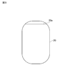
- FIG. 3 is a plan view showing the lower exterior body 20 constituting the deep thermometer 1.
- FIG. 4 is a plan view showing the thermal resistance layer 30 constituting the deep thermometer 1.
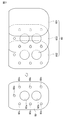
- FIG. 5 is a plan view and a bottom view showing the wiring board 40 constituting the deep thermometer 1.
- FIG. 6 is a plan view showing the flexible substrate 50 constituting the deep thermometer 1.
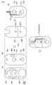
- FIG. 7 is a plan view and an exploded view showing the sticking member 60 having adhesiveness constituting the deep thermometer 1.
- the deep body thermometer 1 is based on the temperature difference detected by the first temperature sensor 701 and the second temperature sensor 702 and the temperature difference detected by the third temperature sensor 703 and the fourth temperature sensor 704. It is a non-heating type depth thermometer which calculates
- the deep thermometer 1 is an affixed (patch type) deep thermometer that is attached to the body surface of a user (subject) and continuously measures body temperature to acquire body temperature data.
- the deep thermometer 1 is a deep thermometer that can prevent the operation switch 406 from being erroneously operated (that is, receiving an incorrect switch operation).
- the deep body thermometer 1 mainly includes an upper exterior body 10, a lower exterior body 20, a body temperature measurement unit 15, a lining member 80, a buffer member 90, and a pasting member 60.
- the body temperature measuring unit 15 mainly includes the thermal resistance layer 30, the second temperature sensor 702, the wiring board 40 on which the fourth temperature sensor 704 is mounted, the first temperature sensor 701, and the third temperature sensor 703.
- a flexible substrate 50 is included.
- the upper exterior body 10 is formed of, for example, a closed cell or semi-closed cell foam material having waterproofness and heat retention.
- the upper exterior body 10 is preferably made of a foam material having low thermal conductivity in order to prevent the temperature of the body temperature measurement unit 15 from locally changing due to a sudden change (change) in the outside air temperature.
- a raw material a polyurethane, a polystyrene, polyolefin, etc. are used suitably, for example.
- vacuum forming is used suitably, for example.
- the upper exterior body 10 has a substantially hat-shaped cross section so that the body temperature measurement unit 15 (the thermal resistor layer 30, the wiring substrate 40, the flexible substrate 50, etc.) can be accommodated. Therefore, the side surface of the thermal resistor layer 30 is covered with the foam material, and the side surface of the thermal resistor layer 30 is prevented from being exposed to the outside air.
- the lower exterior body 20 is formed of, for example, a non-foaming resin film having waterproofness (low moisture permeability) and higher thermal conductivity than the upper exterior body 10.
- the material include polypropylene, polyethylene, polyester, and polyimide, and polyethylene terephthalate (PET) is particularly preferably used.
- PET polyethylene terephthalate
- the lower exterior body 20 is formed in a flat shape (flat) so that the flexible substrate 50 (body temperature measurement unit 15) to which the first temperature sensor 701 and the third temperature sensor 703 are attached can be closely attached.
- the body temperature measurement unit 15 and the lower exterior body 20 may be bonded to each other with a double-sided tape. It is preferable to fix it closely by a method of fixing with an adhesive.
- the sizes (outer dimensions) of the upper and lower outer bodies 10 and 20 are formed to be the same (or substantially the same). For example, the length is about 40 to 100 (mm) and the width is about 20 to 60 (mm). The size is formed.
- the peripheral part of the upper exterior body 10 having a substantially hat-shaped cross section and the peripheral part of the lower exterior body 20 formed in a flat shape are bonded with a double-sided tape or fixed with an adhesive, for example. Or, it is fixed in close contact by heat sealing or the like.
- the body temperature measurement unit 15 is configured by sequentially laminating the flexible substrate 50, the thermal resistor layer 30, and the wiring substrate 40 in this order from the lower exterior body 20 side.
- the thermal resistor layer 30 includes two thermal resistors having different thermal resistance values, that is, a first thermal resistor 301 and a second thermal resistor 302 in order to form two heat fluxes. (See FIG. 4).
- a material having higher thermal conductivity (lower thermal resistance value) than the second thermal resistor 302 for example, plastics such as polypropylene, polyethylene, acrylic, polycarbonate, and epoxy resin is suitable.
- plastics such as polypropylene, polyethylene, acrylic, polycarbonate, and epoxy resin is suitable.
- a material having a lower thermal conductivity (higher thermal resistance value) than the first thermal resistor 301 for example, a foamed plastic (foam material) such as polyurethane, polystyrene, or polyolefin is preferably used.
- thermo conductivity of metals such as copper and aluminum is 100 [W / m / K] or more
- thermal conductivity of plastics such as polypropylene, polyethylene, acrylic, polycarbonate, and epoxy resin is About 0.1 to 0.5 [W / m / K], which is about 3 digits smaller.
- the thermal conductivity of the foamed plastic is an order of magnitude smaller.
- the thermal conductivity of air is even smaller, 0.024 [W / m / K].
- the first thermal resistor 301 and the second thermal resistor 302 are formed to have substantially the same thickness in order to reduce the cost by allowing the wiring substrate 40 and the flexible substrate 50 to be stacked. .
- first thermal resistor 301 constituting the thermal resistor layer 30
- second thermal resistor 302 constituting the thermal resistor layer 30 is formed with a second through hole 302a penetrating in the thickness direction.
- the first through hole 301a is formed so that the first temperature sensor 701 and the second temperature sensor 702 are accommodated inside when viewed in a plan view. That is, a pair of first temperature sensor 701 and second temperature sensor 702 are arranged along the thickness direction of the first thermal resistor 301 inside (inside) the first through hole 301a.
- the second through hole 302a is formed so that the third temperature sensor 703 and the fourth temperature sensor 704 are accommodated inside when viewed in a plan view. That is, the third temperature sensor 703 and the fourth temperature sensor 704 that form a pair are arranged along the thickness direction of the second thermal resistor 302 inside (inside) the second through hole 302a.
- the first temperature sensor 701 to the fourth temperature sensor 704 (hereinafter, collectively referred to as “temperature sensor (corresponding to the biosensor described in claims) 70”), for example, a biosignal A thermistor or a resistance temperature detector whose resistance value changes depending on the temperature is preferably used.
- the temperature sensor 70 preferably has a heat capacity as small as possible from the viewpoint of improving responsiveness. Therefore, for example, a chip thermistor is preferably used as the temperature sensor 70.
- Each of the first temperature sensor 701 to the fourth temperature sensor 704 is electrically connected to a processing circuit (MCU), which will be described later, via a printed wiring, and an electric signal (voltage value) corresponding to the temperature is transmitted to the processing circuit ( MCU).
- MCU processing circuit
- the thermal resistor layer 30 (the first thermal resistor 301 and the second thermal resistor 302). If the layer 30 is made smaller, the difference in the output values of the paired temperature sensors 70 becomes smaller, which may increase the measurement error.
- the temperature sensor 70 chip thermistor
- the thermal resistance layer 30 becomes thin, the thickness cannot be ignored.
- the temperature sensor 70 is in contact with the side surface of the thermal resistor layer 30, heat is transmitted from the contact location, so that the temperature (detected value) of the temperature sensor 70 deviates from the surface temperature of the thermal resistor layer 30. There is a risk of temperature (value). Therefore (in order to reduce the influence), through holes 301 a and 302 a are formed in the thermal resistor layer 30 around the temperature sensor 70, so that the temperature sensor 70 does not contact the side surface of the thermal resistor layer 30.
- the wiring board 40 is, for example, a rigid board such as a glass epoxy board.
- a processing circuit for processing each output signal of the first temperature sensor 701 to the fourth temperature sensor 704 to acquire deep body temperature data is mounted on the wiring board 40.
- a wireless communication unit 403 that transmits (outputs) the acquired deep body temperature data and a coin battery 404 that supplies power to the processing circuit and the wireless communication unit 403 are mounted on the wiring board 40.
- the processing circuit mainly has a temperature input circuit and an arithmetic processing circuit.
- the temperature input circuit includes, for example, an amplifier (for example, an operational amplifier) and an analog / digital converter (A / D converter) in order to read a detection signal (output voltage) of the temperature sensor 70.
- the temperature input circuit amplifies the analog signal output from each temperature sensor 70, converts it into a digital signal, and outputs it to the arithmetic processing circuit.
- the arithmetic processing circuit calculates the deep body temperature from the read measurement (temperature) data.
- the arithmetic processing circuit is configured by, for example, an MCU (Micro Control Unit), EEPROM, RAM, or the like, and calculates the deep body temperature based on the detection value of each temperature sensor 70 read through the temperature input circuit.
- the arithmetic processing circuit stores the calculated deep body temperature data in a memory such as a RAM. Furthermore, the arithmetic processing circuit outputs (transmits) the calculated deep body temperature data wirelessly to an external device by outputting the data to the wireless communication unit 403.
- the arithmetic processing circuit based on the temperature difference between the front and back surfaces of the thermal resistors 301 and 302 generated by the difference between the two heat fluxes formed using the two thermal resistors 301 and 302 having different thermal resistances. Calculate (estimate) deep body temperature. More specifically, the arithmetic processing circuit calculates the deep body temperature Tb based on the following equation (1), for example.
- Tb ⁇ T1 (T3-T4) * Ra1-T3 (T1-T2) * Ra2 ⁇ / ⁇ (T3-T4) * Ra1- (T1-T2) * Ra2 ⁇ (1)
- Tb is the deep body temperature
- T1 is the temperature detected by the first temperature sensor 701
- T2 is the temperature detected by the second temperature sensor 702
- Ra1 is the thermal resistance value of the first thermal resistor 301.
- T3 indicates the temperature detected by the third temperature sensor 703
- T4 indicates the temperature detected by the fourth temperature sensor 704
- Ra2 indicates the thermal resistance value of the second thermal resistor 302.
- the deep body temperature Tb can be uniquely determined by detecting four temperatures (T1, T2, T3, T4).
- a second temperature sensor 702 that acquires the temperature of the upper surface (outside air side) of the first thermal resistor 301, and a fourth temperature that detects the temperature of the upper surface (outside air side) of the second thermal resistor 302.
- a temperature sensor 704 is mounted. More specifically, heat uniformization patterns 401 and 402 that uniformize the temperature distribution in the periphery are formed on the lower surface of the wiring board 40, and one electrode of the second temperature sensor 702 becomes the heat uniformization pattern 401. One electrode of the fourth temperature sensor 704 is connected to the thermal uniform pattern 402.
- the thermal uniform patterns 401 and 402 are formed of a material having high thermal conductivity such as a metal film, for example.
- the back surface side of the wiring layer on which the second temperature sensor 702 and the fourth temperature sensor 704 are mounted It is preferable to provide a uniform member (metal film) with high thermal conductivity that thermally uniforms the influence of the temperature distribution of the outside air temperature on the outside air side.
- a metal foil, a metal thin plate, or the like may be used as the homogenizing member, but in the same manner as the wiring layer formed on the wiring board 40, the wiring pattern (in the inner layer of the wiring board 40 (multilayer rigid board)) ( It is desirable to form it as a solid pattern.
- the inner layer wiring pattern (solid pattern) used as the uniformizing member may be a ground pattern, but is preferably an independent pattern that is not connected to an electric circuit and does not flow current.
- the wireless communication unit 403 transmits the acquired deep body temperature data (biological information) to an external management device or an information terminal (for example, a smartphone).
- the wireless communication unit 403 transmits deep body temperature data to an external management device or information terminal using, for example, Bluetooth (registered trademark).
- a thin coin battery (battery) 404 supplies power to the processing circuit (electronic component) and the wireless communication unit 403 described above.
- the coin battery 404 is accommodated in a battery holder 95 mounted (attached) to the wiring board 40.
- the battery holder 95 is disposed between the wiring board 40 and the lining member 80. That is, the battery holder 95 also serves as a spacer member that supports the lining member 80.
- the communication unit 403 and the coin battery 404 are disposed on the opposite side (upper surface side) of the temperature sensor 70 with the wiring board 40 interposed therebetween.
- An operation switch 406 (hereinafter also referred to as a “power switch”) that accepts a power on / off operation by a user is electrically connected to the wiring board 40 (processing circuit) via the upper exterior body 10.
- a notch is formed in the side portion of the wiring board 40 so that the main surface of the wiring board 40 and the operation direction of the power switch 406 are substantially parallel so as to be accommodated in the notch.
- a power switch 406 is attached. Then, the wiring board 40 is accommodated in an accommodation space defined by the upper exterior body 10 and the lower exterior body 20 so that the power switch 406 faces the back surface (rear surface) of the side surface portion of the upper exterior body 10. The That is, the power switch 406 is disposed on the side surface of the upper exterior body 10.
- the power switch 406 has an operation force input direction substantially parallel to the wiring board 40 and the pasting member 60 (that is, the body surface when pasted on a living body) (that is, from the side of the upper exterior body 10). ) Accepts an operation input, and does not accept an operation input in which the input direction of the operation force is substantially perpendicular to the wiring board 40 and the pasting member 60 (ie, from above).
- the power switch 406 for example, a push button switch or a rocker switch is preferably used. In the case of a push button switch, an alternate operation that maintains an on state even when the fingertip is released is preferable.
- the power switch 406 is preferably a surface mount type, but may be a lead type.
- the power switch 406 is arranged inside the upper exterior body 10 (within the accommodation space) so as not to contact the back surface of the side surface of the upper exterior body 10. More specifically, the distance between the top surface of the button of the power switch 406 and the back surface (back surface) of the side surface portion of the upper exterior body 10 is preferably set to a range of 0 to 4 (mm), for example. More preferably, it is set in the range of 5 to 1.5 (mm).
- the stroke of the power switch 406 is preferably set in the range of 0.1 to 1 (mm), for example, and more preferably in the range of 0.1 to 0.3 (mm).
- an LED 405 that is lit or blinks according to a user's operation or body temperature measurement state (for example, on / off of the power switch 406, measurement start / end, etc.) is mounted.
- a VCSEL or the like may be used instead of the LED.
- an FPC connector 407 for electrically connecting the flexible board 50 is attached to the lower surface side of the wiring board 40.
- the flexible substrate (FPC) 50 is made of, for example, polyimide or polyester (PET) and has flexibility.
- the flexible substrate 50 is mounted with a first temperature sensor 701 that acquires the temperature on the skin side of the first thermal resistor 301 and a third temperature sensor 703 that acquires the temperature on the skin side of the second thermal resistor 302. .
- thermal uniform patterns 501 and 502 are formed in order to make the temperature distribution in the periphery uniform, and one of the first temperature sensors 701 is formed.
- one terminal of the third temperature sensor 703 is connected to the thermal uniformization pattern 502.
- the heat uniform patterns 501 and 502 are made of a material having high thermal conductivity such as a metal film, for example.
- Each of the first temperature sensor 701 and the third temperature sensor 703 is connected to the wiring board 40 (processing circuit) via the wiring pattern 53 and the FPC connector 407, and an electrical signal (voltage value) corresponding to the temperature. Is read by the processing circuit (temperature input circuit). Note that, as described above, the lower exterior body 20, the flexible substrate 50, the thermal resistor layer 30, and the wiring substrate 40 form a heat flux. It is fixed in close contact with.
- a thin plate shape (sheet-like shape) thinner than the buffer member 90 to be described later is provided between the upper exterior body 10 and the buffer member 90 and the battery holder (spacer member) 95. ) Is formed.
- the lining member 80 is formed so as to be able to be bent by, for example, a resin material such as flexible PET. In order to suppress wrinkles of the upper exterior body 10, the lining member 80 is attached by attaching one surface to the back surface (rear surface) of the top surface of the upper exterior body 10 with, for example, a double-sided tape.
- the lining member 80 may be formed from a thin metal plate or the like. Further, in order to prevent the operation of the power switch 406 from being hindered, the lining member 80 may be provided with a notch in accordance with the power switch 406 in the same manner as the wiring board 40 described above.
- a buffer member 90 having a cushioning property (cushioning property) and formed in a plate shape is disposed between the upper surface (main surface) of the wiring board 40 and the lining member 80.
- the buffer member 90 is formed thicker than the height (back height) of the electronic component from the mounting surface of the wiring board 40.
- the buffer member 90 is attached to the other surface of the lining member 80 by, for example, a double-sided tape.
- the sticking member 60 includes a first adhesive layer 601 that is attached to the outer surface of the lower exterior body 20, and a breathable breathable layer 603 that is attached to the first adhesive layer 601 (that is, , A moisture permeable layer that allows moisture to pass through), and a second adhesive layer 602 that is attached to the ventilation layer 603.
- a first adhesive layer 601 that is attached to the outer surface of the lower exterior body 20
- a breathable breathable layer 603 that is attached to the first adhesive layer 601 (that is, , A moisture permeable layer that allows moisture to pass through)
- a second adhesive layer 602 that is attached to the ventilation layer 603.
- a nonwoven fabric for example, a nonwoven fabric can be suitably used.
- a woven fabric or a knitted fabric may be used instead of the non-woven fabric.
- paper, wood, sponge / open cell foam material, etc. may be used, or a plastic, rubber, or metal structure in which grooves or holes from the center to the periphery of the body temperature measuring unit 15 are formed. Also good.
- the air-permeable layer 603 moisture permeable layer
- the thermal conductivity is usually low. Therefore, if the ventilation layer 603 is between the skin, the body temperature measurement accuracy is affected. Therefore (in order to stably measure the body temperature) the first temperature sensor 701, the third temperature sensor 703 for measuring the temperature of the skin, and the region overlapping the heat equalization patterns 501 and 502 connected thereto are provided.
- the ventilation layer 603 is not arranged.
- the ventilation layer 603 moisture permeable layer
- biocompatible double-sided tapes first adhesive layer 601 and second adhesive layer 602 are attached to both surfaces of the nonwoven fabric (breathing layer 603).
- the ventilation layer 603 and the second adhesive layer 602 are formed with through holes 60a and 60b in the thickness direction in which the first temperature sensor 701 and the third temperature sensor 703 are accommodated when viewed in plan.
- the double-sided tape (second adhesive layer 602) usually has a moisture permeability lower than that of the non-woven fabric (ventilation layer 603), at least the second adhesive layer 602 has a plurality of (see FIG. 7) formed in the thickness direction.
- the through holes 60c having a diameter of about 1 to 10 mm at intervals of about 2 to 20 mm.
- a cut having an intersecting portion that is, a cut that intersects in a cross shape
- FIG. 8 is a diagram (No. 1) for explaining a method of assembling the deep body thermometer 1.
- FIG. 9 is a diagram (No. 2) for explaining the assembly method of the deep thermometer 1.
- the deep thermometer 1 is assembled, for example, by the following steps (1) to (6).
- One surface of the thermal resistor layer 30 (the first thermal resistor 301 and the second thermal resistor 302) is adhered and fixed to the back surface of the wiring board 40 with a double-sided tape.
- the coin battery 404 is mounted on the wiring board 40 (that is, inserted into the battery holder 95 mounted on the wiring board 40).
- the flexible substrate 50 side of the body temperature measurement unit 15 (wiring substrate 40, thermal resistor layer 30, flexible substrate 50) is firmly fixed to the center portion of the lower exterior body 20 with a double-sided tape.
- One surface of the lining member 80 is attached to the back surface (back surface) of the upper exterior body 10 with a double-sided tape, and the buffer member 90 is attached to the other surface of the lining member 80 with a double-sided tape.
- the peripheral portion of the upper exterior body 10 to which the lining member 80 and the buffer member 90 are attached and the peripheral portion of the lower exterior body 20 to which the body temperature measuring unit 15 is fixed are closely fixed with a double-sided tape.
- the sticking member 60 is stuck on the bottom surface of the lower exterior body 20.
- the deep thermometer 1 is assembled (manufactured).
- the first temperature sensor 701 and the third temperature sensor 703 are not arranged at symmetrical positions from the center of the lower exterior body 20, a mark 20a for indicating the application direction of the application member 60 is provided. It was attached to the lower exterior body 20.
- the first temperature sensor 701 and the third temperature sensor 703 may be arranged at symmetrical positions from the center of the lower exterior body 20, and the mark 20 a indicating the sticking direction of the sticking member 60 may be eliminated.
- the separator (release paper) attached to the second adhesive layer 602 (double-sided tape) of the sticking member 60 is peeled off. And after pressing the power switch 406 from the outer side (side) of the upper exterior body 10 and turning on a power supply, it affixes on a measurement site
- the power switch 406 since the power switch 406 may be accidentally pressed during the measurement, it is preferable to turn on / off the power by accepting the operation by, for example, a long press for several seconds or more or a plurality of pressings.
- the LED 405 emits light with a predetermined light emission pattern to notify the user that the operation has been accepted.
- the power switch 406 since the power switch 406 is disposed on the side surface of the upper exterior body 10, the power switch 406 has an operation force input direction of the pasting member 60 (that is, When affixed to a living body, an operation input substantially parallel to the body surface (ie, from the side) is accepted, and an operation force input direction is substantially perpendicular to the affixing member 60 (ie, from above). Does not accept input. Therefore, even if a force in a direction substantially perpendicular to the body surface is input to the power switch 406, the operation is not accepted. As a result, it is possible to prevent the power switch 406 from being erroneously operated (that is, receiving an incorrect switch operation).
- the upper exterior body 10 is made of a closed cell or a semi-closed cell foam material having waterproof properties, is formed in a substantially hat shape in a side view, and the sticking member 60 is outside the lower exterior body 20.
- the wiring board 40 is housed in a housing space defined by the upper and lower exterior bodies 10 and 20. Therefore, the power switch 406 can be pressed from the outside of the upper exterior body 10.
- the power switch 406 is disposed inside the upper exterior body 10 (within the accommodation space) so as not to contact the back surface of the side surface portion of the upper exterior body 10. Can be more reliably prevented from being accidentally pressed (accepting an operation).
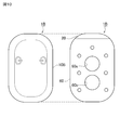
- FIG. 10 is a plan view and a bottom view showing the external appearance of the deep thermometer 1B.
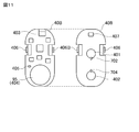
- FIG. 11 is a plan view and a bottom view showing the wiring board 40B constituting the deep thermometer 1B. 10 and 11, the same reference numerals are given to the same or equivalent components as those in the first embodiment.
- the deep thermometer 1B is different from the above-described deep thermometer 1 in that it includes a plurality of (two in this embodiment) operation switches 406 and 406B that receive an operation by the user.
- An operation switch 406 and an operation switch 406B that accept an operation such as power on / off by the user are electrically connected to the wiring board 40B via the upper exterior body 10B.
- a pair of notches are formed on opposite sides of the wiring board 40B, and the operation switch 406 is accommodated in one notch (that is, the other notch is accommodated in one notch).
- the two operation switches 406 and 406B are attached so that the main surface of the wiring board 40B and the operation directions of the operation switches 406 and 406B are substantially parallel to each other. .
- the wiring board 40B is defined by the upper exterior body 10B and the lower exterior body 20 so that each of the operation switch 406 and the operation switch 406B is opposed to the back surface (back surface) of the opposite side surface portion of the upper exterior body 10B.
- the positions of the cutouts are not necessarily symmetrical and may be shifted.
- each of the operation switch 406 and the operation switch 406B is disposed on the side surfaces of the upper exterior body 10B facing each other.
- Each of the two operation switches 406 and 406B may be disposed on a different side surface of the upper exterior body 10B, that is, on a side surface that intersects each other instead of a side surface facing each other.
- the other operation switch 406B may be disposed on the top surface of the upper exterior 10B. That is, it is only necessary that the two operation switches 406 and 406B are not turned on simultaneously by one operation.
- each of the operation switch 406 and the operation switch 406B has an operation force input direction (operation direction) substantially parallel to the wiring board 40B and the attaching member 60 (that is, the body surface when attached to a living body) (ie, the body surface).
- An operation input from the side of the upper exterior body 10B is received, and an operation input in which the operation force input direction (operation direction) is substantially perpendicular to the wiring board 40B and the pasting member 60 (that is, from above) is not received.
- only one of the operation switch 406 and the operation switch 406B has an operation force input direction (operation direction) substantially parallel to the wiring board 40B (that is, the upper exterior body 10B side). It is also possible to adopt a configuration that accepts only an operation input (from the user).
- the operation switches 406 and 406B for example, a push button switch or a rocker switch is preferably used. In the case of a push button switch, an alternate operation that maintains an on state even when the fingertip is released is preferable. Further, as the operation switches 406 and 406B, a surface mount type is preferable, but a lead type may be used. However, the operation switch 406 and the operation switch 406B need not be of the same type, and may be of different types.
- each of the operation switches 406 and 406B push out the upper exterior body 10B in order to prevent the operation switches 406 and 406B from being accidentally pressed (accidentally).
- each of the operation switches 406 and 406B is disposed inside the upper exterior body 10B (within the accommodation space) so as not to contact the back surface of the side surface portion of the upper exterior body 10B.
- an operation is accepted in accordance with a combination of a plurality of operation inputs input to the two operation switches 406 and 406B. At that time, the operation is accepted in consideration of the operation timing of each of the two operation switches 406 and 406B.
- the following functions (1) to (4) can be added.
- the mode is switched (switched). )function.
- the mode include a short-time measurement mode for measuring in a short time, a memory mode (recording mode) for storing measurement data in the internal memory, and a sleep mode.
- the mode in which the measurement of the deep body temperature, the mode in which the measurement of the electrocardiogram or the like is performed in addition to the deep body temperature, and the like can be given.
- Other configurations are the same as or similar to those of the deep thermometer 1 according to the first embodiment described above, and thus detailed description thereof is omitted here.
- the two operation switches 406 and 406B that receive the operation by the user are provided, and the two operation switches 406 and 406B each have an operation direction of the wiring board 40B and the sticking member 60 (that is, the living body).
- an operation input that is substantially parallel to the body surface that is, from the side
- an operation input that is substantially perpendicular to the affixing member 60 that is, from above
- the operation switch 406 is not accepted.
- each of the two operation switches 406 and 406B is disposed on different side surfaces (side surfaces facing each other in the present embodiment) of the upper exterior body 10B. It is possible to prevent the switch 406 from being erroneously operated (that is, accepting an erroneous switch operation).
- an operation is accepted according to a combination of operation inputs input to the two operation switches 406 and 406B and an operation timing of each of the two operation switches 406 and 406B. Therefore, it is possible to add the various functions described above while reliably preventing erroneous operations.
- the present invention is not limited to the above-described embodiments, and various modifications can be made.
- the present invention may be applied to a one-heat-flux-type deep thermometer. It can also be applied to a thermometer other than the deep thermometer.
- the present invention can also be applied to, for example, an electrocardiograph and an adhesive biodevice for measuring respiration and pulse.
- the arrangement of the operation switch 406 (406B) is not limited to the above embodiment, and may be arranged on the other side surface of the upper exterior body 10 (10B). Further, the upper exterior body 10 (10B) having a substantially hat shape may be substantially trapezoidal.
- the operation switch 406 is attached so as to be orthogonal to the wiring board 40 (the sticking member 60), but the operation switch 406 is attached in parallel to the wiring board 40 (the sticking member 60) and the direction of the operating force is changed. It is good also as a structure which changes an input direction using the link mechanism to do. That is, the operation input in the parallel direction (from the side) may be converted into the operation input in the vertical direction (from above) via the link mechanism, and the operation switch 406 may be pressed.
- the shape, size, arrangement, and arrangement of the thermal resistor layer 30 (first thermal resistor 301, second thermal resistor 302), wiring board 40, flexible board 50, lining member 80, and buffer member 90 described above, and
- the arrangement and the like of the first temperature sensor 701 to the fourth temperature sensor 704 are not limited to the above embodiment, and can be arbitrarily set according to requirements such as accuracy.
Landscapes
- Health & Medical Sciences (AREA)
- Life Sciences & Earth Sciences (AREA)
- Physics & Mathematics (AREA)
- Medical Informatics (AREA)
- Surgery (AREA)
- Engineering & Computer Science (AREA)
- Biomedical Technology (AREA)
- Heart & Thoracic Surgery (AREA)
- Biophysics (AREA)
- Molecular Biology (AREA)
- Pathology (AREA)
- Animal Behavior & Ethology (AREA)
- General Health & Medical Sciences (AREA)
- Public Health (AREA)
- Veterinary Medicine (AREA)
- General Physics & Mathematics (AREA)
- Measuring And Recording Apparatus For Diagnosis (AREA)
- Measuring Temperature Or Quantity Of Heat (AREA)
Abstract
L'invention concerne un thermomètre à corps profond (dispositif bioadhésif) (1) comprenant : un corps extérieur supérieur (10) formé à partir d'un matériau en mousse comprenant des cellules fermées ou des cellules semi-fermées étanches à l'eau et formé en une forme de type chapeau à partir d'une vue de surface latérale ; un corps extérieur inférieur (20) dont la section de bord périphérique est collée de manière étanche au corps extérieur supérieur (10) ; un élément adhésif (60) possédant une adhésivité, dont une surface est collée sur la surface extérieure du corps extérieur inférieur (20) ; une carte de circuit imprimé (40) logée dans un espace de logement délimité par le corps extérieur supérieur (10) et le corps extérieur inférieur (20) ; et un commutateur de fonctionnement (406) connecté électriquement à la carte de circuit imprimé (40) qui reçoit un actionnement d'un utilisateur. Le commutateur de fonctionnement (406) reçoit une entrée d'actionnement dont la direction d'entrée de force d'actionnement est approximativement parallèle à l'élément adhésif (60) et ne reçoit pas une entrée d'actionnement dont la direction d'entrée de force d'actionnement est approximativement orthogonale à l'élément adhésif (60).
Priority Applications (3)
| Application Number | Priority Date | Filing Date | Title |
|---|---|---|---|
| JP2020523643A JPWO2019235277A1 (ja) | 2018-06-06 | 2019-05-27 | 貼付型生体用デバイス |
| US17/108,050 US12163846B2 (en) | 2018-06-06 | 2020-12-01 | Sticking-type device for living body |
| JP2022073487A JP2022103213A (ja) | 2018-06-06 | 2022-04-27 | 貼付型生体用デバイス |
Applications Claiming Priority (2)
| Application Number | Priority Date | Filing Date | Title |
|---|---|---|---|
| JP2018108589 | 2018-06-06 | ||
| JP2018-108589 | 2018-06-06 |
Related Child Applications (1)
| Application Number | Title | Priority Date | Filing Date |
|---|---|---|---|
| US17/108,050 Continuation US12163846B2 (en) | 2018-06-06 | 2020-12-01 | Sticking-type device for living body |
Publications (1)
| Publication Number | Publication Date |
|---|---|
| WO2019235277A1 true WO2019235277A1 (fr) | 2019-12-12 |
Family
ID=68769601
Family Applications (1)
| Application Number | Title | Priority Date | Filing Date |
|---|---|---|---|
| PCT/JP2019/020818 Ceased WO2019235277A1 (fr) | 2018-06-06 | 2019-05-27 | Dispositif bioadhésif |
Country Status (3)
| Country | Link |
|---|---|
| US (1) | US12163846B2 (fr) |
| JP (2) | JPWO2019235277A1 (fr) |
| WO (1) | WO2019235277A1 (fr) |
Cited By (1)
| Publication number | Priority date | Publication date | Assignee | Title |
|---|---|---|---|---|
| US11714006B2 (en) * | 2017-12-08 | 2023-08-01 | Murata Manufacturing Co., Ltd. | Thermometer |
Families Citing this family (3)
| Publication number | Priority date | Publication date | Assignee | Title |
|---|---|---|---|---|
| US12556860B2 (en) | 2022-01-14 | 2026-02-17 | Apple, Inc | Electronic device |
| US20230225619A1 (en) * | 2022-01-14 | 2023-07-20 | Apple Inc. | Electronic device |
| US12507353B2 (en) | 2022-01-14 | 2025-12-23 | Apple Inc. | Electronic device |
Citations (7)
| Publication number | Priority date | Publication date | Assignee | Title |
|---|---|---|---|---|
| JP2007195618A (ja) * | 2006-01-24 | 2007-08-09 | Seiko Epson Corp | 生体情報機器 |
| KR20100012871U (ko) * | 2009-06-18 | 2010-12-28 | (주)엠디앤유 | 심전계 |
| JP2016087209A (ja) * | 2014-11-07 | 2016-05-23 | Jsr株式会社 | 生体情報測定システム、及びそれに用いられる生体情報測定用血管脈波データ取得装置 |
| JP2016214731A (ja) * | 2015-05-25 | 2016-12-22 | ローム株式会社 | バイタルセンサモジュールおよびその動作方法 |
| WO2017043595A1 (fr) * | 2015-09-11 | 2017-03-16 | フクダ電子株式会社 | Feuille de capteur |
| JP2017217255A (ja) * | 2016-06-08 | 2017-12-14 | セイコーエプソン株式会社 | 生体情報処理装置および生体情報処理方法 |
| KR101846780B1 (ko) * | 2017-05-15 | 2018-04-09 | 이성원 | 레이저 패치 및 이를 구비하는 레이저 패치 시술 셋트 |
Family Cites Families (14)
| Publication number | Priority date | Publication date | Assignee | Title |
|---|---|---|---|---|
| JPH0629790B2 (ja) | 1984-07-02 | 1994-04-20 | セイコーエプソン株式会社 | 電子体温計 |
| JP3967075B2 (ja) * | 2000-11-13 | 2007-08-29 | テルモ株式会社 | 耳式体温計 |
| JP5159357B2 (ja) * | 2008-02-14 | 2013-03-06 | パナソニック株式会社 | 表示装置および表示装置を備えた自転車および表示装置の回路基板の保持方法 |
| JP2010223743A (ja) | 2009-03-24 | 2010-10-07 | Terumo Corp | 貼り付け型体温計及び貼り付け型体温計を用いた体温測定/管理装置 |
| KR20100131070A (ko) * | 2009-06-05 | 2010-12-15 | 헌 김 | 일정 간격으로 체온을 자동 측정하여 무선으로 측정값을 보내고 받는 방법과 체온측정장치 |
| WO2012129129A2 (fr) * | 2011-03-18 | 2012-09-27 | Augustine Biomedical And Design Llc | Sonde de température centrale non invasive |
| WO2013059658A1 (fr) * | 2011-10-19 | 2013-04-25 | Sympara Medical Inc. | Méthodes et dispositifs pour le traitement de l'hypertension |
| US10575741B2 (en) * | 2014-08-18 | 2020-03-03 | Samsung Electronics Co., Ltd | Wearable biometric information measurement device |
| JP2017099619A (ja) * | 2015-12-01 | 2017-06-08 | 新光電気工業株式会社 | 絆創膏型モジュール |
| CA3009449C (fr) * | 2015-12-23 | 2019-09-10 | Lumiradx Uk Limited | Timbre de surveillance de sante |
| US20180028072A1 (en) * | 2016-07-29 | 2018-02-01 | VivaLnk, Inc. | Wearable thermometer patch capable of measuring human skin temperature at high duty cycle |
| TWI707125B (zh) * | 2016-12-30 | 2020-10-11 | 豪展醫療科技股份有限公司 | 穿戴式體溫監測裝置與方法 |
| US11419549B2 (en) * | 2018-05-16 | 2022-08-23 | Murata Manufacturing Co., Ltd. | Sticking-type device for living body |
| JP6628919B1 (ja) * | 2019-03-25 | 2020-01-15 | シチズン時計株式会社 | 電子体温計 |
-
2019
- 2019-05-27 WO PCT/JP2019/020818 patent/WO2019235277A1/fr not_active Ceased
- 2019-05-27 JP JP2020523643A patent/JPWO2019235277A1/ja active Pending
-
2020
- 2020-12-01 US US17/108,050 patent/US12163846B2/en active Active
-
2022
- 2022-04-27 JP JP2022073487A patent/JP2022103213A/ja active Pending
Patent Citations (7)
| Publication number | Priority date | Publication date | Assignee | Title |
|---|---|---|---|---|
| JP2007195618A (ja) * | 2006-01-24 | 2007-08-09 | Seiko Epson Corp | 生体情報機器 |
| KR20100012871U (ko) * | 2009-06-18 | 2010-12-28 | (주)엠디앤유 | 심전계 |
| JP2016087209A (ja) * | 2014-11-07 | 2016-05-23 | Jsr株式会社 | 生体情報測定システム、及びそれに用いられる生体情報測定用血管脈波データ取得装置 |
| JP2016214731A (ja) * | 2015-05-25 | 2016-12-22 | ローム株式会社 | バイタルセンサモジュールおよびその動作方法 |
| WO2017043595A1 (fr) * | 2015-09-11 | 2017-03-16 | フクダ電子株式会社 | Feuille de capteur |
| JP2017217255A (ja) * | 2016-06-08 | 2017-12-14 | セイコーエプソン株式会社 | 生体情報処理装置および生体情報処理方法 |
| KR101846780B1 (ko) * | 2017-05-15 | 2018-04-09 | 이성원 | 레이저 패치 및 이를 구비하는 레이저 패치 시술 셋트 |
Cited By (1)
| Publication number | Priority date | Publication date | Assignee | Title |
|---|---|---|---|---|
| US11714006B2 (en) * | 2017-12-08 | 2023-08-01 | Murata Manufacturing Co., Ltd. | Thermometer |
Also Published As
| Publication number | Publication date |
|---|---|
| US12163846B2 (en) | 2024-12-10 |
| US20210076945A1 (en) | 2021-03-18 |
| JPWO2019235277A1 (ja) | 2021-05-13 |
| JP2022103213A (ja) | 2022-07-07 |
Similar Documents
| Publication | Publication Date | Title |
|---|---|---|
| US11419549B2 (en) | Sticking-type device for living body | |
| JP2022103213A (ja) | 貼付型生体用デバイス | |
| US11714006B2 (en) | Thermometer | |
| US20180028072A1 (en) | Wearable thermometer patch capable of measuring human skin temperature at high duty cycle | |
| JP7103428B2 (ja) | 貼付型深部体温計 | |
| US11656132B2 (en) | Sticking type thermometer | |
| JP6962342B2 (ja) | 貼付型デバイス | |
| JP6984629B2 (ja) | 貼付型生体用デバイス | |
| JP6537618B2 (ja) | センサーシート | |
| US11828662B2 (en) | Electronic device | |
| US11982572B2 (en) | Stick-on thermometer | |
| JP6962464B2 (ja) | 貼付型深部体温計 | |
| JP7225716B2 (ja) | 貼付部材 |
Legal Events
| Date | Code | Title | Description |
|---|---|---|---|
| 121 | Ep: the epo has been informed by wipo that ep was designated in this application |
Ref document number: 19814167 Country of ref document: EP Kind code of ref document: A1 |
|
| WWE | Wipo information: entry into national phase |
Ref document number: 2020523643 Country of ref document: JP |
|
| NENP | Non-entry into the national phase |
Ref country code: DE |
|
| 122 | Ep: pct application non-entry in european phase |
Ref document number: 19814167 Country of ref document: EP Kind code of ref document: A1 |