WO2019235432A1 - 搾乳器 - Google Patents
搾乳器 Download PDFInfo
- Publication number
- WO2019235432A1 WO2019235432A1 PCT/JP2019/022015 JP2019022015W WO2019235432A1 WO 2019235432 A1 WO2019235432 A1 WO 2019235432A1 JP 2019022015 W JP2019022015 W JP 2019022015W WO 2019235432 A1 WO2019235432 A1 WO 2019235432A1
- Authority
- WO
- WIPO (PCT)
- Prior art keywords
- breast
- hood
- breast pump
- buffer
- sealing
- Prior art date
- Legal status (The legal status is an assumption and is not a legal conclusion. Google has not performed a legal analysis and makes no representation as to the accuracy of the status listed.)
- Ceased
Links
Images




Classifications
-
- A—HUMAN NECESSITIES
- A61—MEDICAL OR VETERINARY SCIENCE; HYGIENE
- A61M—DEVICES FOR INTRODUCING MEDIA INTO, OR ONTO, THE BODY; DEVICES FOR TRANSDUCING BODY MEDIA OR FOR TAKING MEDIA FROM THE BODY; DEVICES FOR PRODUCING OR ENDING SLEEP OR STUPOR
- A61M1/00—Suction or pumping devices for medical purposes; Devices for carrying-off, for treatment of, or for carrying-over, body-liquids; Drainage systems
- A61M1/06—Milking pumps
- A61M1/062—Pump accessories
- A61M1/064—Suction cups
-
- A—HUMAN NECESSITIES
- A61—MEDICAL OR VETERINARY SCIENCE; HYGIENE
- A61M—DEVICES FOR INTRODUCING MEDIA INTO, OR ONTO, THE BODY; DEVICES FOR TRANSDUCING BODY MEDIA OR FOR TAKING MEDIA FROM THE BODY; DEVICES FOR PRODUCING OR ENDING SLEEP OR STUPOR
- A61M1/00—Suction or pumping devices for medical purposes; Devices for carrying-off, for treatment of, or for carrying-over, body-liquids; Drainage systems
- A61M1/06—Milking pumps
-
- A—HUMAN NECESSITIES
- A61—MEDICAL OR VETERINARY SCIENCE; HYGIENE
- A61M—DEVICES FOR INTRODUCING MEDIA INTO, OR ONTO, THE BODY; DEVICES FOR TRANSDUCING BODY MEDIA OR FOR TAKING MEDIA FROM THE BODY; DEVICES FOR PRODUCING OR ENDING SLEEP OR STUPOR
- A61M1/00—Suction or pumping devices for medical purposes; Devices for carrying-off, for treatment of, or for carrying-over, body-liquids; Drainage systems
- A61M1/06—Milking pumps
- A61M1/062—Pump accessories
- A61M1/064—Suction cups
- A61M1/066—Inserts therefor
-
- A—HUMAN NECESSITIES
- A61—MEDICAL OR VETERINARY SCIENCE; HYGIENE
- A61M—DEVICES FOR INTRODUCING MEDIA INTO, OR ONTO, THE BODY; DEVICES FOR TRANSDUCING BODY MEDIA OR FOR TAKING MEDIA FROM THE BODY; DEVICES FOR PRODUCING OR ENDING SLEEP OR STUPOR
- A61M1/00—Suction or pumping devices for medical purposes; Devices for carrying-off, for treatment of, or for carrying-over, body-liquids; Drainage systems
- A61M1/06—Milking pumps
- A61M1/069—Means for improving milking yield
- A61M1/0697—Means for improving milking yield having means for massaging the breast
Definitions
- the present invention relates to a breast pump that generates negative pressure for milking and sucks breast milk.
- Patent Literature 1 discloses a breast pump provided with a storage container, a breast pump main body, a milking diameter-enlarged portion, and a buffer portion.
- the milking diameter expansion part of the breast pump described in Patent Document 1 is an enlarged diameter part for contacting the breast of the user, and is provided in the breast pump main body.
- the buffer part of the milking machine described in patent document 1 is formed in the substantially circular trumpet shape along the opening part of the milking enlarged diameter part, and is arrange
- the buffer part of the breast pump described in Patent Document 1 is formed of an elastic body such as silicone rubber, and has a through hole, a areola contact part, and a breast contact part.
- the through-hole exposes the nipple in a state where the user's breast is in contact with the expanded milk diameter portion.
- the areola contact portion is a protrusion or a concentric protrusion provided near the through hole, and contacts the user's areola portion.
- the breast close contact part is a concentric protrusion provided at a position outside the areola contact part, and is in close contact with the breast of the user.
- Such a buffer part has a function of suppressing irritation and pain caused by the milking expanded part coming into contact with the breast, and a function of suppressing negative pressure generated in the milking expanded part from leaking outside the milking expanded part. Have.
- the buffer part disclosed in Patent Document 1 extends from the outer edge of the milking enlarged part to the milking part air passage of the milking enlarged part in a state of being attached to the milking enlarged part. That is, in the state where the buffer portion is mounted on the milking diameter increasing portion, the portion of the through hole of the buffering portion is disposed in the milking portion air passage corresponding to the inner portion of the milking diameter expanding portion.
- the user's nipple is disposed in the vicinity of the through hole of the buffer portion. Further, the user's areola part contacts the areola contact part of the buffer part.
- the buffer part disclosed in Patent Document 1 is deformed by the negative pressure generated in the expanded milking part at the time of milking, and is rubbed near the user's nipple or areola, or near the user's nipple or areola. Sometimes it gets caught. Thereby, the user may feel pain and discomfort during milking. In this regard, there is room for improvement in the buffer portion disclosed in Patent Document 1.
- the portion of the through hole of the buffer portion is disposed in the milking portion air passage corresponding to the inner portion of the milking diameter-expanded portion. Therefore, when the user attaches the buffer part to the milking enlarged part, a relatively large frictional force is generated between the buffer part and the milking enlarged part, or the buffer part is caught on the outer edge of the milking enlarged part. Sometimes. Thereby, it may take time to mount the buffer portion on the milking enlarged diameter portion, or the buffer portion may not be appropriately attached to the milking enlarged diameter portion.
- the present invention has been made to solve the above-described problems, and provides a breast pump that can reduce irritation and pain applied to a user's breast and can improve wearability of a buffer portion. For the purpose.
- the subject is a breast pump body that generates negative pressure for milking, a hood that is connected to the breast pump body and applied to the breast, and is detachably attached to the hood.
- a ring-shaped buffer portion which is made of a material softer than the material of the hood and has elasticity, and the hood is connected to the breast pump body and passes through the breast milk squeezed from the breast A flow path portion, and a diameter-expanded portion that expands from the flow path portion toward an edge on the opposite side of the flow path portion and is applied to the breast, and the buffer portion includes the edge And a sealing part that is provided on the opposite side of the joint part and is in close contact with the inner surface of the enlarged diameter part between the flow path part and the edge part. Solved by milking machine.
- the hood applied to the breast is connected to the breast pump body that generates negative pressure for milking, and has a flow path portion and a diameter-expanded portion.
- the channel part is connected to the breast pump body.
- Breast milk squeezed from the user's breast passes through the flow path.
- the diameter of the enlarged diameter portion increases from the flow path portion toward the edge on the side opposite to the flow path portion.
- the enlarged diameter portion is applied to the user's breast.
- the buffer portion has a ring shape, is detachably attached to the hood, is formed of a material softer than the hood material, and has elasticity.
- a buffer part has a junction part fitted in the edge of a hood, and a sealing part provided in the opposite side to a junction part.
- the sealing portion is in close contact with the inner surface of the enlarged diameter portion between the flow path portion of the hood and the edge portion of the hood.
- the buffer portion of the breast pump according to the present invention does not extend from the edge portion of the hood to the flow channel portion in the state where it is attached to the hood, but from the edge portion of the hood to the edge portion of the hood and the flow channel portion. It extends to the part between. That is, in a state where the buffer portion is attached to the hood, the sealing portion is disposed on the side of the opening where the breast is inserted as viewed from the flow path portion. At this time, the edge of the opening corresponds to the edge of the hood.
- the nipple of the user enters the flow path portion of the hood.
- the user's areola part is disposed in the vicinity of the boundary part between the flow path part and the diameter-enlarged part. For this reason, even when the breast is inserted into the hood or when it is deformed by the negative pressure generated in the hood during milking, the shock absorber rubs near the user's nipple or areola, or the user's nipple or It is possible to suppress pinching around the areola. Thereby, the milking machine which concerns on this invention can reduce the irritation
- the buffer portion does not extend from the edge portion of the hood to the flow path portion in a state where it is attached to the hood, but between the edge portion of the hood and the edge portion of the hood and the flow path portion. It extends to the part. Therefore, when the user attaches the buffer portion to the hood, the frictional force generated between the buffer portion and the hood can be reduced, or the buffer portion can be prevented from being caught on the edge of the hood. For this reason, it is possible to prevent the mounting of the buffer portion on the hood from being troublesome and the buffer portion from being appropriately mounted on the hood. Thereby, the milking machine which concerns on this invention can improve the mounting
- the outer diameter of the tip of the sealing part is larger than the inner diameter of the enlarged-diameter part where the tip of the sealing part comes into contact.
- the breast pump according to the present invention in a state where the buffer portion is attached to the hood, a force in a direction perpendicular to the inner surface of the enlarged diameter portion is applied from the sealing portion to the enlarged diameter portion. That is, since the outer diameter of the tip of the sealing part is larger than the inner diameter of the part of the enlarged diameter part with which the tip of the sealing part comes into contact, virtually, the distal end of the sealing part is the enlarged diameter part with which the tip of the sealing part comes into contact I will bite into the part. On the other hand, since the material of the buffer portion is softer than the material of the hood, in reality, the tip of the sealing portion cannot bite into the portion of the enlarged diameter portion where the tip of the sealing portion contacts.
- the tip of the sealing part tends to deform toward the inside of the enlarged diameter part.
- the buffer part has elasticity, if the tip of the sealing part is compressed toward the inside of the enlarged diameter part and is deformed, the force generated inside the tip part of the sealing part is the entire tip part of the sealing part.
- the tip portion of the sealing portion can apply a force toward the inner surface of the enlarged diameter portion in a state where wrinkles are suppressed. Therefore, in a state where the buffer portion is mounted on the hood, a force in a direction perpendicular to the inner surface of the enlarged diameter portion is applied from the sealing portion to the enlarged diameter portion.
- the adhesiveness between a sealing part and an enlarged diameter part can be improved, and it can suppress that mother's milk penetrate
- the buffer portion protrudes from the enlarged diameter portion toward the inside of the enlarged diameter portion between the joint portion and the sealing portion, and is separated from the inner surface of the enlarged diameter portion. It further has a cushion part provided in the position.
- the cushion portion provided between the joint portion and the sealing portion protrudes from the enlarged diameter portion toward the inside of the enlarged diameter portion and is separated from the inner surface of the enlarged diameter portion. Therefore, a space is provided between the cushion portion and the enlarged diameter portion.
- This space can function as an air cushion.
- the cushion part can fit the user's breast gently and ensure good skin contact, and can also ensure the airtightness of the space surrounded by the breast, the buffer part and the hood.
- the buffer portion is a bent portion provided at a boundary between the cushion portion and the sealing portion, and is bent when the cushion portion is deformed, and the cushion portion is deformed. It further has a bent portion that suppresses transmission to the sealing portion.
- the bent portion provided at the boundary between the cushion portion and the sealing portion is bent when the cushion portion is deformed, and the deformation of the cushion portion is prevented from being transmitted to the sealing portion. That is, when the breast is inserted into the hood and contacts the cushion portion, the cushion portion is deformed and crushed. At this time, the bent portion provided at the boundary between the cushion portion and the sealing portion is bent, and the deformation of the cushion portion is prevented from being transmitted to the sealing portion.
- a bending part suppresses that a sealing part deform
- the thickness of the joint portion is larger than the thickness of the sealing portion.
- the breast pump according to the present invention can increase the rigidity of the joint. Thus, the user can easily attach the buffer portion to the hood.
- a breast pump that can reduce irritation and pain applied to a user's breast and can improve the wearing ability of the buffer portion.
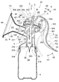
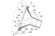
- FIG. 2 is a cross-sectional view taken along a cutting plane A11-A11 shown in FIG. 1 of the breast pump according to the present embodiment. It is the top view which looked at the milking machine concerning this embodiment from the top. It is sectional drawing showing the milking machine which concerns on a comparative example. It is sectional drawing showing the state before the buffer part of this embodiment is mounted
- the milking apparatus 2 according to the present embodiment will be described with reference to FIGS.
- the milking apparatus 2 according to the present embodiment is used when it is difficult to give breast milk directly to an infant, when the nipple is damaged, when preventing mastitis, and the like, and a device that can be operated and operated by the user It is.
- the breast pump 2 shown in FIGS. 1 to 3 is a manual breast pump that can be manually operated by a user to suck breast milk.
- the milking machine which concerns on this embodiment is not necessarily limited to a manual milking machine, The electric milking machine which obtains the motive power required for milking operation by electricity may be sufficient. In the following description, a case where the breast pump is a manual breast pump is taken as an example.
- the breast pump 2 includes a breast pump body 3, a hood 4, and a buffer portion 7.
- the milking machine 2 may further include a diaphragm 34, a handle 5, a holding member 200, and a bottle 6.
- the breast pump body 3 is formed of a relatively light and hard synthetic resin material. Examples of the material of the breast pump main body 3 include polypropylene, polycarbonate, polycycloolefin, polyether sulfone, and polyphenyl sulfone.
- a first passage 312 is formed in the mounting portion 311 to which the hood 4 is mounted. As shown in FIG. 2, the first passage 312 is connected to the upper portion in the breast pump main body 3 via the internal space S ⁇ b> 3 formed in the substantially central portion in the breast pump main body 3 and the second passage 321. It is spatially connected to the part S4.
- the internal space S3 is a space for storing breast milk in which the squeezed breast milk is temporarily stored.
- a diaphragm 34 is detachably provided on the upper portion of the breast pump body 3.
- the diaphragm 34 is integrally formed of an elastic body such as a synthetic resin, and has flexibility as a whole.
- the lower end portion 344 of the diaphragm 34 is attached so as to cover the outer periphery of a substantially disc-shaped diaphragm mounting portion 32 ⁇ / b> R provided in the upper part of the breast pump main body 3. That is, the diaphragm 34 is mounted above the diaphragm mounting portion 32 ⁇ / b> R of the breast pump body 3.
- the negative pressure space S5 formed between the breast pump body 3 and the diaphragm 34 is a region (space) to which negative pressure is applied.
- the negative pressure space S5 formed between the breast pump main body 3 and the diaphragm 34 is in a negative pressure state.
- the axis C is the axial direction of the coupling portion 35.
- the hood 4 is connected to the breast pump body 3 and applied to the breast.
- the hood 4 is formed in a trumpet shape or a substantially dome shape corresponding to the shape of the breast, and has a flow path portion 41 and an enlarged diameter portion 42.
- the channel portion 41 is the smallest diameter portion of the hood 4 and is connected to the mounting portion 311 provided in the breast pump main body 3. That is, the flow path portion 41 has a portion connected to the breast pump main body 3, and is disposed on the back side of the breast pump main body 3 in the hood 4, that is, when viewed from the opening 44 of the hood 4.
- the inner diameter of the channel portion 41 is substantially constant.
- the enlarged diameter portion 42 is a portion whose diameter increases from the flow channel portion 41 toward the edge 43 on the opposite side of the flow channel portion 41, and is applied to the breast.
- the edge 43 corresponds to the edge of the opening 44 of the hood 4.
- the space S1 When the user inserts the breast into the space S1 surrounded by the hood 4 shown in FIG. 2, the space S1 has an accommodation space S2 for accommodating the user's nipple so as to be sealed.
- the accommodation space S2 is set to a negative pressure, so that a milkable structure is formed.
- the user's nipple enters the flow path portion 41.
- the user's nipple is exposed inside the flow path portion 41.
- the areola around the nipple is disposed in the vicinity of the boundary between the flow path portion 41 and the enlarged diameter portion 42 (see FIG. 6).
- the buffer portion 7 has a ring shape and is detachably attached to the hood 4.
- the buffer portion 7 includes a joint portion 71 and a sealing portion 72, and is fitted and attached to the edge 43 of the hood 4 at the joint portion 71.
- the buffer portion 7 may further include a cushion portion 73 and a bent portion 74.
- the buffer portion 7 is made of a material softer than the material of the hood 4 and has elasticity.
- the buffer portion 7 is a material that can be easily deformed, such as silicone rubber, elastomer, natural rubber, and the like, and is formed of a material that easily adheres to the breast of the user during milking.
- the material of the buffer part 7 is preferably a silicone rubber having a hardness of about 20 to 80 according to A-type durometer in JIS-K6253 (ISO7619). .
- the joint 71 is fitted to the edge 43 of the hood 4.
- the joint portion 71 is provided with a groove portion that can be fitted to the edge portion 43 of the hood 4.
- the joint 71 is attached to the edge 43 of the hood 4.
- the sealing part 72 is provided on the side opposite to the joint part 71. That is, the joint portion 71 is provided at one end of the buffer portion 7. As shown in FIG. 2, the sealing portion 72 is in close contact with the inner surface 421 of the enlarged diameter portion 42 of the hood 4 between the flow path portion 41 of the hood 4 and the edge portion 43 of the hood 4.
- the buffer portion 7 is formed in a trumpet shape or a funnel shape corresponding to the inner surface 421 of the enlarged diameter portion 42 of the hood 4. At least a part of the buffer portion 7 is in close contact with the inner surface 421 of the enlarged diameter portion 42 of the hood 4.
- the buffer portion 7 uses a function of suppressing irritation and pain caused by the enlarged diameter portion 42 coming into contact with the user's breast, and a negative pressure set in the accommodation space S2 surrounded by the user's breast and the hood 4 is used. A function of suppressing leakage from the breast side of the person. Details of the buffer 7 will be described later.
- an opening 313 is formed below the internal space S3, and a backflow prevention valve 36 is attached.
- a backflow prevention valve 36 As the backflow prevention valve 36 of the present embodiment, for example, an on-off valve called a duckbill valve is employed. However, the backflow prevention valve 36 is not limited to a duckbill valve.
- the backflow prevention valve 36 prevents the milk or air passing through the opening 313 from backflowing from the bottle 6, thereby making the accommodation space S ⁇ b> 2 more effectively in a negative pressure state.
- the backflow prevention valve 36 is integrally formed of an elastic body such as synthetic resin, and has flexibility as a whole. Examples of the material of the backflow prevention valve 36 include silicone rubber, elastomer, natural rubber, and the like.
- the backflow prevention valve 36 shown in FIG. 2 has a slit 36S at the tip.
- the slit 36S is closed when the negative pressure space S5 is in a negative pressure state. That is, when the negative pressure space S5 is in a negative pressure state, the internal space S3 is in a negative pressure state through the communication portion S4 and the second passage 321. Then, the slit 36S of the check valve 36 is closed. For this reason, the internal space S3 can be in a negative pressure state through the first passage 312 while ensuring high sealing performance.
- the breast pump main body 3 has an attaching / detaching portion 314 that is detachably attached to the bottle 6 at the lower end portion.
- the detachable part 314 has a dome shape or a cylindrical shape.
- a female screw part 315 is provided inside the attaching / detaching part 314.
- a male screw portion 61 is provided outside the upper end portion of the bottle 6.
- the female screw part 315 of the detachable part 314 and the male screw part 61 of the bottle 6 can be screwed together.
- the bottle 6 may be a dedicated product for the breast pump 2 or a baby bottle that can be adapted to the detachable portion 314.
- the bottle 6 may be a bag shape instead of a molded container.
- the diaphragm 34 shown in FIG. 2 is a negative pressure generating member for generating a negative pressure.
- the diaphragm 34 is connected to the diaphragm mounting portion 32 ⁇ / b> R at the top of the breast pump main body 3.
- a negative pressure space S5 is formed between the main body 3 and the diaphragm 34.
- the diaphragm 34 is formed of a relatively deformable and flexible deformable material, that is, a synthetic resin having a hardness of about 30 to 70 according to A-type durometer in JIS-K6253 (ISO7619).
- a relatively deformable and flexible deformable material that is, a synthetic resin having a hardness of about 30 to 70 according to A-type durometer in JIS-K6253 (ISO7619).
- the material of the diaphragm 34 include silicone rubber, isoprene rubber, elastomer such as SEBS (styrene-ethylene-butylene-styrene), and the like. In the present embodiment, silicone rubber is used as the material of the diaphragm 34.
- the coupling portion 35 is attached to the bottom surface portion 343 of the diaphragm 34 at the lower portion and is connected to the handle 5 at the upper portion.
- the diaphragm 34 deforms when it receives the action of the reciprocating motion of the handle 5 at the bottom surface portion 343 via the coupling portion 35. If it does so, the bottom face part 343 will be pulled up to the coupling
- the negative pressure space S5 becomes a negative pressure state.
- air in the first passage 312 is sucked through the communication portion S4, the second passage 321 and the internal space S3, and breast milk is sucked (milked).
- the coupling portion 35 is formed of a hard material that is harder than the material of the diaphragm 34.
- Examples of the material of the coupling portion 35 include synthetic resins such as polypropylene, polycarbonate, polycycloolefin, and polyethersulfone.
- the coupling portion 35 has a flat disc-shaped base portion 351.
- the base 351 is disposed on the lower side (negative pressure space S5 side) of the bottom surface part 343.
- the coupling portion 35 has a connecting portion 352 that protrudes upward from the base portion 351 and extends in an axial shape.
- the connecting portion 352 is detachably connected to the handle 5. Specifically, the connecting portion 352 is inserted into a through hole (a hole having a smaller diameter than the base portion 351) formed in the center portion of the bottom surface portion 343 of the diaphragm 34, and is exposed above the bottom surface portion 343. It can be connected to the handle 5.
- the base 351 pulls up the bottom surface portion 343 of the diaphragm 34. Then, the diaphragm 34 is deformed to enlarge the negative pressure space S5.
- the base portion 351 of this embodiment is disposed below the bottom surface portion 343 of the diaphragm 34 without being connected to the bottom surface portion 343.
- the installation form of the base 351 is not limited to this.
- the base 351 may be fixed to the upper side of the bottom surface part 343.
- the connecting portion 352 has a first protruding portion 353 and a second protruding portion 354 that are arranged side by side in the extending direction Z of the connecting portion 352.
- Each of the first protruding portion 353 and the second protruding portion 354 protrudes from the shaft portion of the connecting portion 352 in the radially outward direction.
- a first engaging portion 355 is provided between the first protruding portion 353 and the second protruding portion 354.
- the first engaging portion 355 is a recessed portion (groove portion) between the first protruding portion 353 and the second protruding portion 354.
- a second engaging portion 356 is provided between the second projecting portion 354 and the base portion 351.
- the second engaging portion 356 is a recessed portion (groove portion) between the second projecting portion 354 and the base portion 351.
- the holding member 200 is attached to the breast pump body 3 and is provided to be rotatable with respect to the breast pump body 3.
- the handle 5 rotates with respect to the breast pump main body 3 together with the holding member 200 as indicated by arrows A ⁇ b> 3 and A ⁇ b> 4 shown in FIG. 3.
- the holding member 200 does not necessarily have to rotate with respect to the breast pump body 3.
- the holding member 200 includes an attachment part 400 and an extension part 323.
- the attachment portion 400 is sandwiched between the diaphragm mounting portion 32R and the receiving portion 501, and is fitted in a rotatable state with respect to the breast pump main body 3.
- the extension part 323 is formed extending from the attachment part 400, and supports the handle 5 so as to be able to reciprocate.
- the handle 5 shown in FIG. 2 is held by the holding member 200 and supported so as to be capable of reciprocating with respect to the extension 323 of the holding member 200. That is, the handle 5 can reciprocate in the directions of arrows A1 and A2 shown in FIGS.
- the handle 5 is detachably connected to the connecting portion 352 by engaging with the first engaging portion 355 or the second engaging portion 356. Thereby, the connection position in the extending
- the first engaging portion 355 and the second engaging portion 356 are formed stepwise apart from each other in the extending direction Z. Therefore, the distance by which the handle 5 pulls up the connecting portion 352 can be changed step by step according to the engagement position between the handle 5 and the engaging portions 355 and 356.
- the handle 5 has a long shape, and is formed of a relatively hard and lightweight synthetic resin as a whole.
- the material for the handle 5 include polypropylene, polycarbonate, polycycloolefin, and polyethersulfone.
- the handle 5 is disposed above the diaphragm 34, and includes a lift part 53 that lifts the diaphragm 34, and a lever part 52 that is bent from the lift part 53 and positioned on the side surface of the breast pump main body 3.
- the lift portion 53 is provided with a connected portion 54 that is connected to the connecting portion 352.
- the connected portion 54 includes a holding opening 541 for holding the connecting position of the connecting portion 352 and an insertion opening 542 for inserting the connecting portion 352.
- the holding opening 541 and the insertion opening 542 are spatially connected to each other.
- the first protruding portion 353 and the second protruding portion 354 have the inner diameter. It is smaller than each outer diameter.
- the inner diameter of the insertion opening 542 is larger than the outer diameter of each of the first protrusion 353 and the second protrusion 354 shown in FIG. Accordingly, after the user inserts the connecting portion 352 into the insertion opening 542, the user slides the connecting portion 352 toward the holding opening 541 to hold the first engaging portion 355 or the second engaging portion 356.
- the handle 5 and the connecting portion 352 can be positioned relative to each other by being placed in the portion 541.
- the lever portion 52 is formed in a lever shape and plays the role of a handle.
- the area outside the lever portion 52 corresponds to an area where the user places a finger FG other than the thumb. That is, the outer surface of the lever portion 52 corresponds to a surface on which the user applies a finger FG other than the thumb.
- the distance between the outer surface of the lever portion 52 where the user applies the finger FG and the recess portion 317 in the breast pump main body 3 for the user to place the thumb TB is the distance between the outer surface of the lever portion 52 and the recess portion 317. It is the distance which a user can hold
- the handle 5 rotates about the axial direction X of the support shaft portion 324 of the holding member 200 (see arrows A5 and A6 shown in FIG. 2).
- the lift part 53 of the handle 5 lifts the diaphragm 34 upward via the coupling part 35.
- the volume of the space of the negative pressure space S5 expands to be in a negative pressure state.
- the accommodation space S2 is in a negative pressure state via the second passage 321, the internal space S3, and the first passage 312 of the communication portion S4. In this way, milking of breast milk is performed.
- the lever portion 52 is gradually curved outward as it goes downward from the region where the finger FG is placed.
- steering-wheel 5 exhibits the external appearance which bounces a little outside. Therefore, the finger FG can be prevented from shifting to the lower side of the handle 5 when the user brings the lever portion 52 close to the breast pump main body 3.
- a breast pump 2A according to the comparative example includes a breast pump body 3, a hood 4, and a buffer portion 7A.
- the milking machine 2A according to the comparative example may further include a diaphragm 34, a handle 5, a holding member 200, and a bottle 6.
- the buffer portion 7 ⁇ / b> A extends from the edge portion 43 of the hood 4 to the flow path portion 41 of the hood 4 when the hood 4 is attached.
- the end portion 72 ⁇ / b> A opposite to the opening portion of the buffer portion 7 ⁇ / b> A corresponds to the back portion of the hood 4 when the buffer portion 7 ⁇ / b> A is attached to the hood 4. It is arranged in the channel part 41 to be.
- the user's nipple is disposed in the flow path portion 41.
- the user's areola portion is disposed in the vicinity of the boundary portion between the flow path portion 41 and the enlarged diameter portion 42.
- the buffer portion 7A is rubbed near the user's nipple or areola, or near the user's nipple or areola. Sometimes it gets caught. Thereby, the user may feel pain and discomfort during milking.
- the breast pump 2A when the user attaches the buffer portion 7A to the hood 4, a relatively large frictional force is generated between the buffer portion 7A and the hood 4, or the buffer portion 7A The hood 4 may be caught on the edge 43. Accordingly, it may take time to mount the buffer portion 7A on the hood 4 or the buffer portion 7A may not be properly mounted on the hood 4. If the buffer portion 7A is not properly attached to the hood 4, the adhesion of the buffer portion 7A to the hood 4 is reduced, and the negative pressure generated in the accommodation space S2 may leak from the breast side of the user.
- the buffer portion 7 does not extend from the edge portion 43 of the hood 4 to the flow path portion 41 in the state of being attached to the hood 4. It extends from the portion 43 to a portion between the edge portion 43 of the hood 4 and the flow path portion 41. That is, in a state where the buffer portion 7 is mounted on the hood 4, the sealing portion 72 is disposed on the opening 44 side of the hood 4 where the breast is inserted as viewed from the flow path portion 41 of the hood 4. Specifically, the sealing portion 72 is disposed in the enlarged diameter portion 42 between the edge portion 43 and the flow path portion 41, and is in close contact with the inner surface 421 of the enlarged diameter portion 42.
- the breast pump 2 which concerns on this embodiment can reduce the irritation
- the buffer portion 7 does not extend from the edge portion 43 of the hood 4 to the flow path portion 41 in a state where it is attached to the hood 4, but from the edge portion 43 of the hood 4 to the edge portion of the hood 4. It extends to a portion between 43 and the flow path portion 41. Therefore, when the user attaches the buffer portion 7 to the hood 4, the frictional force generated between the buffer portion 7 and the hood 4 is reduced or the buffer portion 7 is caught on the edge 43 of the hood 4. It can be suppressed. Therefore, it can be prevented that the mounting of the buffer portion 7 on the hood 4 takes time and the buffer portion 7 is not properly mounted on the hood 4. Thereby, the milking machine 2 which concerns on this embodiment can improve the mounting
- the buffer 7 is detachably attached to the hood 4. 5
- the user moves the buffer portion 7 toward the hood 4 and hooks the edge portion 43 of the hood 4 into the groove portion of the joint portion 71 of the buffer portion 7. 7 can be attached to the hood 4.
- the thickness T1 of the joint portion 71 is thicker than the thickness T2 of the sealing portion 72. Therefore, the rigidity of the joining part 71 is higher than the rigidity of the sealing part 72.
- the rigidity of the junction part 71 can be improved. As a result, the user can easily attach the buffer portion 7 to the hood 4.
- the space S1 accommodates the user's nipple K so as to be sealed. It has accommodation space S2.
- the user's nipple K enters the flow path portion 41.
- the user's nipple K is exposed inside the flow path portion 41.
- the areola part N around the nipple K is disposed in the vicinity of the boundary between the flow path part 41 and the enlarged diameter part 42.
- the sealing portion 72 of the present embodiment is disposed in the enlarged diameter portion 42 between the edge portion 43 and the flow path portion 41 and is in close contact with the inner surface 421 of the enlarged diameter portion 42. Therefore, even when the breast B is inserted into the hood 4 or when it is deformed by the negative pressure generated in the accommodation space S2 during milking, the buffer 7 is located near the nipple K or the areola N of the user. It is possible to suppress rubbing and pinching the vicinity of the user's nipple K and areola N. Thereby, the breast pump 2 which concerns on this embodiment can reduce the irritation
- the outer diameter D ⁇ b> 1 of the tip of the sealing portion 72 is larger than the inner diameter D ⁇ b> 2 of the portion of the enlarged diameter portion 42 with which the tip of the sealing portion 72 contacts when the buffer portion 7 is attached to the hood 4. Slightly larger.
- the force in the direction perpendicular to the inner surface 421 of the enlarged diameter portion 42 is expanded from the sealing portion 72 in a state where the buffer portion 7 is attached to the hood 4. Joins the diameter portion 42. That is, since the outer diameter D1 of the tip of the sealing portion 72 is larger than the inner diameter D2 of the portion of the enlarged diameter portion 42 with which the tip of the sealing portion 72 contacts, virtually, the tip of the sealing portion 72 is It will bite into the part of the enlarged diameter part 42 which a front-end
- the tip of the sealing portion 72 cannot actually bite into the portion of the enlarged diameter portion 42 that the tip of the sealing portion 72 contacts. Therefore, the tip of the sealing portion 72 tends to deform toward the inside of the enlarged diameter portion 42.
- the buffer part 7 has elasticity, when the tip of the sealing part 72 is compressed toward the inside of the enlarged diameter part 42 and is deformed, the force generated inside the tip part of the sealing part 72 is the sealing part 72. Dispersed throughout the tip of the. Therefore, the tip portion of the sealing portion 72 can apply a force toward the inner surface 421 of the enlarged diameter portion 42 in a state where wrinkles are suppressed.
- the buffer portion 7 has a cushion portion 73.
- the cushion portion 73 is provided on the entire circumference between the joint portion 71 and the sealing portion 72.
- the cushion portion 73 protrudes from the enlarged diameter portion 42 toward the inside of the enlarged diameter portion 42, and is provided at a position away from the inner surface 421 of the enlarged diameter portion 42.
- a space 75 is provided between the cushion portion 73 of the buffer portion 7 and the enlarged diameter portion 42 of the hood 4.
- the space 75 can function as an air cushion.
- the cushion portion 73 can gently fit the user's breast B and ensure good skin contact, and also ensure the airtightness of the space S2 surrounded by the breast B, the buffer portion 7, and the hood 4. it can.
- the buffer portion 7 has a bent portion 74.
- the bent portion 74 is a portion provided at the boundary between the cushion portion 73 and the sealing portion 72 and is provided as a folding margin portion, a fold line portion or a step portion between the cushion portion 73 and the sealing portion 72.
- the bent portion 74 is bent when the cushion portion 73 is deformed, and prevents the deformation of the cushion portion 73 from being transmitted to the sealing portion 72. That is, when the user inserts the breast B into the space S ⁇ b> 1 surrounded by the hood 4 through the opening 44 of the hood 4, the breast B comes into contact with the cushion portion 73.
- the cushion portion 73 gently fits the user's breast B as an air cushion portion and ensures good skin contact.
- the cushion part 73 deform transforms and is crushed like arrow A9 represented to FIG.
- the space 75 between the cushion portion 73 and the enlarged diameter portion 42 is crushed.
- the bent portion 74 is bent to suppress the deformation of the cushion portion 73 from being transmitted to the sealing portion 72.
- the bent portion 74 and the sealing portion 72 move toward the flow path portion 41 along the inner surface 421 of the enlarged diameter portion 42 as indicated by an arrow A10 illustrated in FIG. That is, the bent portion 74 and the sealing portion 72 move toward the enlarged diameter portion 42 having a smaller inner diameter.
- the force applied to the inner surface 421 of the enlarged diameter portion 42 from the bent portion 74 and the sealing portion 72 increases.
- the bending part 74 suppresses that the sealing part 72 deform
- holding member 311 ... mounting part , 312 ... 1st passage, 313 ... opening, 3 4 ... Detachable part, 315 ... Female thread part, 316 ... Opening part, 317 ... Recessed part, 321 ... Second passage, 322 ... Groove part, 323 ... Extension part, 324: support shaft part, 343 ... bottom face part, 344 ... lower end part, 351 ... base part, 352 ... coupling part, 353 ... first projecting part, 354 ... second Protruding part, 355 ... 1st engaging part, 356 ... 2nd engaging part, 400 ... mounting part, 421 ... inner surface, 501 ... receiving part, 541 ... holding opening 542 ...
Landscapes
- Health & Medical Sciences (AREA)
- Heart & Thoracic Surgery (AREA)
- Biomedical Technology (AREA)
- Vascular Medicine (AREA)
- Engineering & Computer Science (AREA)
- Anesthesiology (AREA)
- Pediatric Medicine (AREA)
- Hematology (AREA)
- Life Sciences & Earth Sciences (AREA)
- Animal Behavior & Ethology (AREA)
- General Health & Medical Sciences (AREA)
- Public Health (AREA)
- Veterinary Medicine (AREA)
- External Artificial Organs (AREA)
Abstract
【課題】使用者の乳房に与える刺激や痛みを低減することができるとともに、緩衝部の装着性を向上させることができる搾乳器を提供すること。 【解決手段】搾乳器2は、搾乳のための負圧を生成する搾乳器本体3と、搾乳器本体3に接続され乳房にあてがわれるフード4と、フード4に対して着脱自在に装着されフード4の材料よりも柔らかい材料により形成され弾性を有する緩衝部7と、を備える。フード4は、搾乳器本体3に接続され乳房から搾られた母乳が通過する流路部41と、流路部41から流路部41とは反対側の縁部43に向かって径が拡大し乳房にあてがわれる拡径部42と、を有する。緩衝部7は、縁部43に嵌められる接合部71と、接合部71とは反対側に設けられ流路部41と縁部43との間において拡径部42の内面421に密着するシーリング部72と、を有する。
Description
本発明は、搾乳のために負圧を生成し母乳を吸引する搾乳器に関する。
従来から、使用者の母乳を吸引する搾乳器が知られている。例えば、特許文献1には、収容容器と、搾乳器本体と、搾乳拡径部と、緩衝部と、を備えた搾乳器が開示されている。特許文献1に記載された搾乳器の搾乳拡径部は、使用者の乳房に当接されるための拡径部分であり、搾乳器本体に設けられている。特許文献1に記載された搾乳器の緩衝部は、搾乳拡径部の開口部に沿ったほぼ円形のラッパ形状に形成され、搾乳拡径部に着脱自在に配置されている。緩衝部の少なくとも一部は、使用者の乳房に当接する。
特許文献1に記載された搾乳器の緩衝部は、シリコーンゴムなどの弾性体により形成され、貫通孔と、乳輪当接部と、乳房密着部と、を有する。貫通孔は、使用者の乳房が搾乳拡径部に当接した状態で乳首を露出させる。乳輪当接部は、貫通孔の近傍に設けられた突起もしくは同心円状の突出部であり、使用者の乳輪部に当接する。乳房密着部は、乳輪当接部よりも外側の位置に設けられた同心円状の突出部であり、使用者の乳房に密着する。このような緩衝部は、搾乳拡径部が乳房に当接することにより生ずる刺激や痛みを抑える機能と、搾乳拡径部に生じた負圧が搾乳拡径部の外部に漏れることを抑える機能と、を有する。
ここで、特許文献1に開示された緩衝部は、搾乳拡径部に装着された状態において、搾乳拡径部の外縁から搾乳拡径部の搾乳部通気路まで延びている。すなわち、緩衝部が搾乳拡径部に装着された状態において、緩衝部の貫通孔の部分は、搾乳拡径部のうちの奥の部分に相当する搾乳部通気路に配置されている。一方で、使用者が乳房を搾乳拡径部に挿入すると、使用者の乳首は緩衝部の貫通孔の近傍に配置される。また、使用者の乳輪部は、緩衝部の乳輪当接部に当接する。そのため、特許文献1に開示された緩衝部は、搾乳時において搾乳拡径部に生じた負圧により変形し、使用者の乳頭や乳輪付近に擦れたり、使用者の乳頭や乳輪付近を挟んだりすることがある。これにより、使用者は、搾乳時に痛みや不快を感ずることがある。この点において、特許文献1に開示された緩衝部には改善の余地がある。
また、前述したように、緩衝部の貫通孔の部分は、搾乳拡径部のうちの奥の部分に相当する搾乳部通気路に配置される。そのため、使用者が緩衝部を搾乳拡径部に装着するときに、比較的大きい摩擦力が緩衝部と搾乳拡径部との間に発生したり、緩衝部が搾乳拡径部の外縁に引っ掛かったりすることがある。これにより、搾乳拡径部に対する緩衝部の装着に手間が掛かったり、緩衝部が搾乳拡径部に適切に装着されなかったりすることがある。緩衝部が搾乳拡径部に適切に装着されないと、搾乳拡径部に対する緩衝部の密着性が低下し、搾乳拡径部に生じた負圧が搾乳拡径部の外部に漏れることがある。この点において、特許文献1に開示された緩衝部には改善の余地がある。
本発明は、前記課題を解決するためになされたものであり、使用者の乳房に与える刺激や痛みを低減することができるとともに、緩衝部の装着性を向上させることができる搾乳器を提供することを目的とする。
前記課題は、本発明によれば、搾乳のための負圧を生成する搾乳器本体と、前記搾乳器本体に接続され乳房にあてがわれるフードと、前記フードに対して着脱自在に装着されるリング状の緩衝部であって前記フードの材料よりも柔らかい材料により形成され弾性を有する緩衝部と、を備え、前記フードは、前記搾乳器本体に接続され前記乳房から搾られた母乳が通過する流路部と、前記流路部から前記流路部とは反対側の縁部に向かって径が拡大し前記乳房にあてがわれる拡径部と、を有し、前記緩衝部は、前記縁部に嵌められる接合部と、前記接合部とは反対側に設けられ前記流路部と前記縁部との間において前記拡径部の内面に密着するシーリング部と、を有することを特徴とする搾乳器により解決される。
本発明に係る搾乳器によれば、乳房にあてがわれるフードは、搾乳のための負圧を生成する搾乳器本体に接続され、流路部と、拡径部と、を有する。流路部は、搾乳器本体に接続されている。使用者の乳房から搾られた母乳は、流路部を通過する。拡径部の径は、流路部から流路部とは反対側の縁部に向かって拡大している。拡径部は、使用者の乳房にあてがわれる。また、緩衝部は、リング状を呈し、フードに対して着脱自在に装着され、フードの材料よりも柔らかい材料により形成されて弾性を有する。緩衝部は、フードの縁部に嵌められる接合部と、接合部とは反対側に設けられたシーリング部と、を有する。シーリング部は、フードの流路部と、フードの縁部と、の間において拡径部の内面に密着する。
これにより、本発明に係る搾乳器の緩衝部は、フードに装着された状態において、フードの縁部から流路部まで延びるわけではなく、フードの縁部からフードの縁部と流路部との間の部分まで延びている。すなわち、緩衝部がフードに装着された状態において、シーリング部は、流路部からみて乳房が挿入される開口部の側に配置される。このとき、開口部の縁部は、フードの縁部に相当する。一方で、使用者がフードの開口部を通してフードにより囲まれた空間に乳房を挿入すると、使用者の乳首は、フードの流路部に入り込む。また、使用者の乳輪部は、流路部と拡径部との境界部の近傍に配置される。そのため、乳房をフード内に挿入する際や、搾乳時においてフードに生じた負圧により変形した場合であっても、緩衝部が使用者の乳頭や乳輪付近に擦れたり、使用者の乳頭や乳輪付近を挟んだりすることを抑えることができる。これにより、本発明に係る搾乳器は、使用者の乳頭や乳輪に与える刺激や痛みを低減することができる。
また、前述したように、緩衝部は、フードに装着された状態において、フードの縁部から流路部まで延びるわけではなく、フードの縁部からフードの縁部と流路部との間の部分まで延びている。そのため、使用者が緩衝部をフードに装着するときにおいて、緩衝部とフードとの間に発生する摩擦力を低減したり、緩衝部がフードの縁部に引っ掛かることを抑えたりすることができる。そのため、フードに対する緩衝部の装着に手間が掛かったり、緩衝部がフードに適切に装着されなかったりすることを抑えことができる。これにより、本発明に係る搾乳器は、緩衝部の装着性を向上させ、フードに生じた負圧がフードの外部に漏れることを抑えることができる。
本発明に係る搾乳器において、好ましくは、前記シーリング部の先端の外径は、前記シーリング部の先端が接触する前記拡径部の部分の内径よりも大きいことを特徴とする。
本発明に係る搾乳器によれば、緩衝部がフードに装着された状態において、拡径部の内面に対して垂直な方向の力がシーリング部から拡径部に加わる。すなわち、シーリング部の先端が接触する拡径部の部分の内径よりもシーリング部の先端の外径が大きいため、仮想的には、シーリング部の先端は、シーリング部の先端が接触する拡径部の部分に食い込むことになる。一方で、緩衝部の材料がフードの材料よりも柔らかいため、現実的には、シーリング部の先端は、シーリング部の先端が接触する拡径部の部分に食い込むことはできない。そのため、シーリング部の先端は、拡径部の内側に向かって変形しようとする。このとき、緩衝部は弾性を有するため、シーリング部の先端が拡径部の内側に向かって圧縮され変形しようとすると、シーリング部の先端部分の内部に生ずる力は、シーリング部の先端部分の全体に分散する。そのため、シーリング部の先端部分は、皺が生ずることを抑えられた状態で、拡径部の内面に向かって力を与えることができる。そのため、緩衝部がフードに装着された状態において、拡径部の内面に対して垂直な方向の力がシーリング部から拡径部に加わる。これにより、シーリング部と拡径部との間の密着性を向上させ、母乳がシーリング部と拡径部との間に侵入することを抑えることができる。
本発明に係る搾乳器において、好ましくは、前記緩衝部は、前記接合部と前記シーリング部との間において前記拡径部から前記拡径部の内側に向かって突出し前記拡径部の内面から離れた位置に設けられたクッション部をさらに有することを特徴する。
本発明に係る搾乳器によれば、接合部とシーリング部との間に設けられたクッション部は、拡径部から拡径部の内側に向かって突出し、拡径部の内面から離れている。そのため、クッション部と拡径部との間には、空間が設けられている。この空間は、エアクッションとして機能することができる。これにより、クッション部は、使用者の乳房に優しくフィットし肌当たりの良さを確保するとともに、乳房と緩衝部とフードとにより囲まれた空間の気密性を確保することができる。
本発明に係る搾乳器において、好ましくは、前記緩衝部は、前記クッション部と前記シーリング部との境界に設けられた屈曲部であって前記クッション部が変形したときに屈曲し前記クッション部の変形が前記シーリング部に伝わることを抑制する屈曲部をさらに有することを特徴とする。
本発明に係る搾乳器によれば、クッション部とシーリング部との境界に設けられた屈曲部は、クッション部が変形したときに屈曲し、クッション部の変形がシーリング部に伝わることを抑制する。すなわち、乳房がフードに挿入されクッション部に接触すると、クッション部が変形し潰れる。このとき、クッション部とシーリング部との境界に設けられた屈曲部は、屈曲し、クッション部の変形がシーリング部に伝わることを抑える。これにより、屈曲部は、クッション部が変形した場合であっても、シーリング部が変形したり拡径部から浮き上がったりすることを抑え、シーリング部と拡径部との間の密着性を確保することができる。
本発明に係る搾乳器において、好ましくは、前記接合部の肉厚は、前記シーリング部の肉厚よりも厚いことを特徴とする。
本発明に係る搾乳器によれば、接合部の剛性を高めることができる。これにより、使用者は、緩衝部をフードに容易に装着することができる。
本発明によれば、使用者の乳房に与える刺激や痛みを低減することができるとともに、緩衝部の装着性を向上させることができる搾乳器を提供することができる。
以下に、本発明の好ましい実施形態を、図面を参照して詳しく説明する。
なお、以下に説明する実施形態は、本発明の好適な具体例であるから、技術的に好ましい種々の限定が付されているが、本発明の範囲は、以下の説明において特に本発明を限定する旨の記載がない限り、これらの態様に限られるものではない。また、各図面中、同様の構成要素には同一の符号を付して詳細な説明は適宜省略する。
なお、以下に説明する実施形態は、本発明の好適な具体例であるから、技術的に好ましい種々の限定が付されているが、本発明の範囲は、以下の説明において特に本発明を限定する旨の記載がない限り、これらの態様に限られるものではない。また、各図面中、同様の構成要素には同一の符号を付して詳細な説明は適宜省略する。
図1~図3を参照して、本実施形態に係る搾乳器を説明する。本実施形態に係る搾乳器2は、乳児に直接母乳を与えることが困難な場合、乳頭が傷ついている場合、乳腺炎を予防する場合などに用いられ、使用者が操作をして搾乳できる器具である。図1~図3に表した搾乳器2は、使用者が手動で操作をして母乳を吸引できる手動搾乳器である。なお、本実施形態に係る搾乳器は、手動搾乳器に限定されるわけではなく、搾乳動作に必要な動力を電動により得る電動搾乳器であってもよい。以下の説明では、搾乳器が手動搾乳器である場合を例に挙げる。
図1および図2に示すように、搾乳器2は、搾乳器本体3と、フード4と、緩衝部7と、を備える。搾乳器2は、ダイヤフラム34と、ハンドル5と、保持部材200と、ボトル6と、さらに備えていてもよい。
搾乳器本体3は、比較的軽く、かつ、硬質な合成樹脂材料により成形されている。搾乳器本体3の材料としては、例えば、ポリプロピレン、ポリカーボネート、ポリシクロオレフィン、ポリエーテルサルフォン、ポリフェニルサルフォン等が挙げられる。フード4が装着される装着部311の内部には、気体や搾られた母乳などが通過する第1通路312が形成されている。図2に示すように、第1通路312は、搾乳器本体3内の略中央部に形成された内部空間S3および第2通路321を介して、搾乳器本体3内の上部に形成された連通部S4と空間的に繋がっている。内部空間S3は、搾られた母乳が一時的に貯留される母乳貯留用の空間である。
搾乳器本体3の上部には、ダイヤフラム34が着脱可能に設けられている。ダイヤフラム34は、例えば合成樹脂等の弾性体により一体成形されており、全体として可撓性を有する。ダイヤフラム34の下端部344は、搾乳器本体3の上部に設けられた略円盤状のダイヤフラム装着部32Rの外周を覆って取り付けられている。すなわち、ダイヤフラム34は、搾乳器本体3のダイヤフラム装着部32Rの上方に装着されている。
搾乳器本体3とダイヤフラム34との間に形成された陰圧空間S5は、負圧が付与される領域(空間)である。ダイヤフラム34が軸Cに沿って形状変化することにより、搾乳器本体3とダイヤフラム34との間に形成された陰圧空間S5が負圧状態になる。軸Cは、結合部35の軸方向である。陰圧空間S5が負圧状態になると、収容空間S2は、第1通路312と、内部空間S3と、第2通路321と、連通部S4と、を介して負圧状態になる。このように、搾乳器本体3は、使用者の母乳を吸引するための負圧、すなわち搾乳のための負圧を生成する。
フード4は、搾乳器本体3に接続され、乳房にあてがわれる。フード4は、乳房の形状に対応するラッパ状または略ドーム状に形成され、流路部41と、拡径部42と、を有する。流路部41は、フード4のうちで最も径の小さい部分であり、搾乳器本体3に設けられた装着部311に接続される。つまり、流路部41は、搾乳器本体3に接続される部分を有し、フード4のうちで搾乳器本体3の側、すなわちフード4の開口部44からみて奥側に配置される。流路部41の内径は、略一定である。拡径部42は、流路部41から流路部41とは反対側の縁部43に向かって径が拡大した部分であり、乳房にあてがわれる。縁部43は、フード4の開口部44の縁部に相当する。
使用者が、図2に示すフード4により囲まれた空間S1に乳房を挿入すると、空間S1は、使用者の乳首を密封するように収容する収容空間S2を有するようになる。収容空間S2が負圧に設定されることで、搾乳可能な構造が形成される。このとき、使用者の乳房が緩衝部7および拡径部42に接触した状態において、使用者の乳首は、流路部41に入り込む。言い換えれば、使用者の乳首は、流路部41の内部に露出する。また、乳首の周囲の乳輪部は、流路部41と拡径部42との境界部の近傍に配置される(図6参照)。
緩衝部7は、リング状を呈し、フード4に対して着脱自在に装着される。具体的には、緩衝部7は、接合部71と、シーリング部72と、を有し、接合部71においてフード4の縁部43に嵌められ装着されている。緩衝部7は、クッション部73と、屈曲部74と、をさらに有していてもよい。緩衝部7は、フード4の材料よりも柔らかい材料により形成され、弾性を有する。例えば、緩衝部7は、シリコーンゴムやエラストマー、天然ゴム等の容易に変形可能な材料であって、搾乳時に使用者の乳房に密着し易い材料により形成されている。例えば、緩衝部7の材料としてシリコーンゴムが使用される場合には、緩衝部7の材料は、JIS-K6253(ISO7619)におけるA型デュロメータによる硬度がHS20~80程度のシリコーンゴムであることが好ましい。
接合部71は、フード4の縁部43に嵌められる。具体的には、接合部71には、フード4の縁部43に嵌合可能な溝部が設けられている。フード4の縁部43が接合部71の溝部に引っ掛けられることにより、接合部71は、フード4の縁部43に取り付けられる。シーリング部72は、接合部71とは反対側に設けられている。すなわち、接合部71は、緩衝部7の一方の端部に設けられている。図2に表したように、シーリング部72は、フード4の流路部41と、フード4の縁部43と、の間においてフード4の拡径部42の内面421に密着する。
このように、緩衝部7は、フード4の拡径部42の内面421に対応しラッパ状またはロート状に形成されている。そして、緩衝部7の少なくとも一部は、フード4の拡径部42の内面421に密着している。緩衝部7は、拡径部42が使用者の乳房に当接することにより生ずる刺激や痛みを抑える機能と、使用者の乳房とフード4により囲まれた収容空間S2に設定された負圧が使用者の乳房側から漏れることを抑える機能と、を有する。緩衝部7の詳細については、後述する。
図2に示すように、内部空間S3の下側には、開口部313が形成され、逆流防止弁36が取り付けられている。本実施形態の逆流防止弁36には、例えばダックビル弁と呼ばれる開閉弁が採用されている。ただし、逆流防止弁36は、ダックビル弁だけには限定されない。逆流防止弁36は、開口部313を通過する母乳や空気がボトル6から逆流することを防止することで、収容空間S2をより効果的に負圧状態にする。逆流防止弁36は、例えば合成樹脂等の弾性体により一体成形され、全体として可撓性を有する。逆流防止弁36の材料としては、例えば、シリコーンゴムやエラストマー、天然ゴム等などが挙げられる。
図2に示す逆流防止弁36は、先端にスリット36Sを有している。スリット36Sは、陰圧空間S5を負圧状態にすると閉じる。すなわち、陰圧空間S5が負圧状態になると、内部空間S3は、連通部S4および第2通路321を介して負圧状態になる。そうすると、逆流防止弁36のスリット36Sは、閉じる。そのため、内部空間S3は高い密閉性を確保しながら、第1通路312を介して収容空間S2を負圧状態にすることができる。
また、逆流防止弁36および内部空間S3に母乳が貯留した状態で、陰圧空間S5の負圧が解除されると、逆流防止弁36のスリット36Sは、母乳の重量や負圧の解除(常圧への変化)によって開き、貯留されていた母乳は、ボトル6内の空間S6に導かれる。図2に示すように、搾乳器本体3は、ボトル6に対して着脱可能に設けられた着脱部314を下端部に有する。着脱部314は、ドーム状あるいは筒状を呈している。ボトル6内の空間S6は、逆流防止弁36が開口部313を開放したときに、内部空間S3に連通する。
図2に示すように、着脱部314の内側には、雌ネジ部315が設けられている。一方で、ボトル6の上端部の外側には、雄ネジ部61が設けられている。着脱部314の雌ネジ部315と、ボトル6の雄ネジ部61と、は互いに螺合可能とされている。なお、ボトル6は、搾乳器2の専用品でもよいし、着脱部314に適合可能な哺乳瓶等であってもよい。また、ボトル6は、成形された容器ではなく、袋状とされていてもよい。
図2に示すダイヤフラム34は、負圧を発生させるための負圧発生部材である。本実施形態では、ダイヤフラム34は、搾乳器本体3の上部のダイヤフラム装着部32Rに接続されている。ダイヤフラム34がダイヤフラム装着部32Rに装着されることで、本体3とダイヤフラム34との間に陰圧空間S5が形成される。
ダイヤフラム34は、比較的弾性に富んだ柔軟な変形材料、すなわち、JIS-K6253(ISO7619)におけるA型デュロメータによる硬度がHS30~70程度の合成樹脂により形成されている。ダイヤフラム34の材料としては、例えば、シリコーンゴムやイソプレンゴム、SEBS(スチレン-エチレン-ブチレン-スチレン)等のエラストマー等が挙げられる。本実施形態では、ダイヤフラム34の材料としてシリコーンゴムが利用される。
図2に示すように、結合部35は、下部においてダイヤフラム34の底面部343に取り付けられ、上部においてハンドル5と連結されている。ダイヤフラム34は、結合部35を介してハンドル5の往復動作の作用を底面部343で受けると変形する。そうすると、底面部343が結合部35に引き上げられ、底面部343と搾乳器本体3の上部との間に形成された陰圧空間S5の空間の容積が変化する。これにより、ダイヤフラム34は、陰圧空間S5に対して一定量の負圧を付与する。つまり、ダイヤフラム34の変形により、陰圧空間S5が負圧状態になる。陰圧空間S5が負圧状態になると、連通部S4、第2通路321および内部空間S3を介して、第1通路312内の空気が吸引され、母乳が吸引(搾乳)される。
結合部35は、ダイヤフラム34の材料よりも硬い硬質材料で形成されている。結合部35の材料としては、例えば、ポリプロピレン、ポリカーボネート、ポリシクロオレフィン、ポリエーテルサルフォン等の合成樹脂が挙げられる。結合部35は、平たい円盤状の基部351を有する。基部351は、底面部343の下側(陰圧空間S5側)に配置されている。
また、結合部35は、基部351から上方に突出して軸状に延びた連結部352を有する。連結部352は、ハンドル5に対して着脱可能に連結する。具体的には、連結部352は、ダイヤフラム34の底面部343の中央部に形成された通し孔(基部351よりも小径な孔)に挿通されて、底面部343の上側に露出することで、ハンドル5に連結可能とされている。連結部352に連結されたハンドル5を使用者が引き上げると、基部351がダイヤフラム34の底面部343を引き上げる。そうすると、ダイヤフラム34が変形して陰圧空間S5を拡大させる。なお、本実施形態の基部351は、ダイヤフラム34の底面部343の下側において、底面部343には接続せずに配置されている。但し、基部351の設置形態は、これだけには限定されない。例えば、基部351は、底面部343の上側に固定されていてもよい。
図2に表したように、連結部352は、連結部352の延伸方向Zにおいて互いに並んで配置された第1突出部353および第2突出部354を有する。第1突出部353および第2突出部354のそれぞれは、連結部352の軸部から径外方向に突出している。第1突出部353と第2突出部354との間には、第1係合部355が設けられている。第1係合部355は、第1突出部353と第2突出部354との間において窪んだ部分(溝部分)である。また、第2突出部354と基部351との間には、第2係合部356が設けられている。第2係合部356は、第2突出部354と基部351との間において窪んだ部分(溝部分)である。
保持部材200は、搾乳器本体3に取り付けられ、搾乳器本体3に対して回転可能に設けられている。保持部材200が搾乳器本体3に対して回転すると、図3に表した矢印A3および矢印A4のように、ハンドル5は、保持部材200とともに搾乳器本体3に対して回転する。なお、本実施形態に係る搾乳器2では、保持部材200は、必ずしも搾乳器本体3に対して回転しなくともよい。図1に示すように、保持部材200は、取付部400と、延長部323と、を有する。取付部400は、ダイヤフラム装着部32Rと、受け部501と、の間に挟設され、搾乳器本体3に対して回転可能な状態で嵌められている。延長部323は、取付部400から延長して形成され、ハンドル5を往復運動可能に支持する。
図2に示すハンドル5は、保持部材200に保持されているとともに、保持部材200の延長部323に対して往復運動可能に支持されている。すなわち、ハンドル5は、図1および図2に示す矢印A1および矢印A2の方向に往復運動を行うことができる。ハンドル5は、第1係合部355または第2係合部356と係合することにより、連結部352と着脱可能に連結している。これにより、ハンドル5と連結部352との延伸方向Zにおける連結位置は、変更可能とされている。そのため、ハンドル5が連結部352を引き上げる距離は、変更可能とされている。これにより、ダイヤフラム34の変形量を変更することができる。すなわち、図2に表したように、第1係合部355および第2係合部356は、延伸方向Zにおいて互いに離れて段階的に形成されている。そのため、ハンドル5と係合部355、356との係合位置に応じて、ハンドル5が連結部352を引き上げる距離は、段階的に変更可能とされている。
ハンドル5は、長尺の形状を有し、全体として、比較的硬質であって軽量な合成樹脂により成形されている。ハンドル5の材料としては、例えば、ポリプロピレン、ポリカーボネート、ポリシクロオレフィン、ポリエーテルサルフォン等が挙げられる。ハンドル5は、ダイヤフラム34の上方に配置されて、ダイヤフラム34を持ち上げるリフト部53と、リフト部53から曲折して搾乳器本体3の側面に位置するレバー部52と、を有する。
図3に示すように、リフト部53には、連結部352と連結される被連結部54が設けられている。被連結部54は、連結部352の連結位置を保持するための保持開口部541と、連結部352を挿入するための挿入開口部542と、を有する。保持開口部541と挿入開口部542とは、互いに空間的に接続されている。
保持開口部541の内径は、図2に示す第1係合部355および第2係合部356のそれぞれの外径よりも僅かに大きい一方で、第1突出部353および第2突出部354のそれぞれの外径よりも小さい。これに対して、挿入開口部542の内径は、図2に示す第1突出部353および第2突出部354のそれぞれの外径よりも大きい。これにより、使用者は、連結部352を挿入開口部542に挿入した後、連結部352を保持開口部541に向かってスライドさせて第1係合部355または第2係合部356を保持開口部541に入れることにより、ハンドル5と連結部352とを互いに位置決めすることができる。
図2に示すように、レバー部52は、レバー状に形成され、取手の役割を果たす。レバー部52の外側の領域は、使用者が親指以外の指FGを置く領域に相当する。つまり、レバー部52の外側表面は、使用者が親指以外の指FGを当てる表面に相当する。使用者が指FGを当てるレバー部52の外側表面と、使用者が親指TBを置くための搾乳器本体3にある窪み部317と、の距離は、レバー部52の外側表面と、窪み部317と、の間に搾乳器本体3を挟んで使用者が把持できる程度の距離である。
使用者が搾乳器本体3を挟んで把持した手を握ることで、レバー部52は、搾乳器本体3に向かって押されて搾乳器本体3に接近する。そうすると、ハンドル5が保持部材200の支軸部324の軸方向Xを中心に回転する(図2に表した矢印A5および矢印A6参照)。そうすると、ハンドル5のリフト部53は、結合部35を介してダイヤフラム34を上に持ち上げる。そして、陰圧空間S5の空間の容積が拡大して負圧状態となる。これにより、収容空間S2は、連通部S4の第2通路321、内部空間S3、および第1通路312を介して負圧状態になる。このようにして、母乳の搾乳が行われる。
図2に示すように、レバー部52は、指FGを置く領域から下側に向かうに従って、除々に外側に向かうように湾曲している。これにより、ハンドル5の下端部55は、やや外側に跳ねるような外観を呈する。そのため、使用者がレバー部52を搾乳器本体3に接近させた場合において、指FGがハンドル5の下側にずれることを抑えることができる。
ここで、図4を参照して、比較例に係る搾乳器2Aを説明する。比較例に係る搾乳器2Aは、搾乳器本体3と、フード4と、緩衝部7Aと、を備える。比較例に係る搾乳器2Aは、ダイヤフラム34と、ハンドル5と、保持部材200と、ボトル6と、さらに備えていてもよい。比較例に係る搾乳器2Aでは、緩衝部7Aが、フード4に装着された状態において、フード4の縁部43からフード4の流路部41まで延びている。すなわち、比較例に係る搾乳器2Aでは、緩衝部7Aがフード4に装着された状態において、緩衝部7Aの開口部とは反対側の端部72Aが、フード4のうちの奥の部分に相当する流路部41に配置されている。一方で、使用者がフード4により囲まれた空間S1に乳房を挿入すると、使用者の乳首は流路部41に配置される。また、使用者の乳輪部は、流路部41と拡径部42との境界部の近傍に配置される。そうすると、乳房をフード4内に挿入する際や、収容空間S2に生じた負圧により変形し、緩衝部7Aが使用者の乳頭や乳輪付近に擦れたり、使用者の乳頭や乳輪付近を挟んだりすることがある。これにより、使用者は、搾乳時に痛みや不快を感ずることがある。また、比較例に係る搾乳器2Aでは、使用者が緩衝部7Aをフード4に装着するときに、比較的大きい摩擦力が緩衝部7Aとフード4との間に発生したり、緩衝部7Aがフード4の縁部43に引っ掛かったりすることがある。これにより、フード4に対する緩衝部7Aの装着に手間が掛かったり、緩衝部7Aがフード4に適切に装着されなかったりすることがある。緩衝部7Aがフード4に適切に装着されないと、フード4に対する緩衝部7Aの密着性が低下し、収容空間S2に生じた負圧が使用者の乳房側から漏れることがある。
これに対して、本実施形態に係る搾乳器2では、緩衝部7は、フード4に装着された状態において、フード4の縁部43から流路部41まで延びるわけではなく、フード4の縁部43からフード4の縁部43と流路部41との間の部分まで延びている。すなわち、緩衝部7がフード4に装着された状態において、シーリング部72は、フード4の流路部41からみて乳房が挿入されるフード4の開口部44の側に配置される。具体的には、シーリング部72は、縁部43と流路部41との間の拡径部42に配置され、拡径部42の内面421に密着している。一方で、使用者がフード4の開口部44を通してフード4により囲まれた空間S1に乳房を挿入すると、使用者の乳首は、流路部41に入り込む。また、使用者の乳輪部は、流路部41と拡径部42との境界部の近傍に配置される。そのため、乳房をフード4内に挿入する際や、搾乳時においての収容空間S2に生じた負圧により変形した場合であっても、緩衝部7が使用者の乳頭や乳輪付近に擦れたり、使用者の乳頭や乳輪付近を挟んだりすることを抑えることができる。これにより、本実施形態に係る搾乳器2は、使用者の乳房に与える刺激や痛みを低減することができる。
また、前述したように、緩衝部7は、フード4に装着された状態において、フード4の縁部43から流路部41まで延びるわけではなく、フード4の縁部43からフード4の縁部43と流路部41との間の部分まで延びている。そのため、使用者が緩衝部7をフード4に装着するときにおいて、緩衝部7とフード4との間に発生する摩擦力を低減したり、緩衝部7がフード4の縁部43に引っ掛かることを抑えたりすることができる。そのため、フード4に対する緩衝部7の装着に手間が掛かったり、緩衝部7がフード4に適切に装着されなかったりすることを抑えことができる。これにより、本実施形態に係る搾乳器2は、緩衝部7の装着性を向上させ、収容空間S2に生じた負圧が使用者の乳房側から漏れることを抑えることができる。
次に、図5~図7を参照して、本実施形態の緩衝部およびフードをさらに説明する。
図5および図6に表したように、緩衝部7は、フード4に対して着脱自在に装着される。図5に表した矢印A7のように、使用者は、緩衝部7をフード4に向かって移動させ、フード4の縁部43を緩衝部7の接合部71の溝部に引っ掛けることにより、緩衝部7をフード4に装着することができる。接合部71の肉厚T1は、シーリング部72の肉厚T2よりも厚い。そのため、接合部71の剛性は、シーリング部72の剛性よりも高い。このように、本実施形態の緩衝部7によれば、接合部71の剛性を高めることができる。これにより、使用者は、緩衝部7をフード4に容易に装着することができる。
図5および図6に表したように、緩衝部7は、フード4に対して着脱自在に装着される。図5に表した矢印A7のように、使用者は、緩衝部7をフード4に向かって移動させ、フード4の縁部43を緩衝部7の接合部71の溝部に引っ掛けることにより、緩衝部7をフード4に装着することができる。接合部71の肉厚T1は、シーリング部72の肉厚T2よりも厚い。そのため、接合部71の剛性は、シーリング部72の剛性よりも高い。このように、本実施形態の緩衝部7によれば、接合部71の剛性を高めることができる。これにより、使用者は、緩衝部7をフード4に容易に装着することができる。
図6に表したように、使用者が、フード4の開口部44を通してフード4により囲まれた空間S1に乳房Bを挿入すると、空間S1は、使用者の乳首Kを密封するように収容する収容空間S2を有するようになる。このとき、使用者の乳房Bが緩衝部7および拡径部42に接触した状態において、使用者の乳首Kは、流路部41に入り込む。言い換えれば、使用者の乳首Kは、流路部41の内部に露出する。また、乳首Kの周囲の乳輪部Nは、流路部41と拡径部42との境界部の近傍に配置される。
本実施形態のシーリング部72は、縁部43と流路部41との間の拡径部42に配置され、拡径部42の内面421に密着している。そのため、乳房Bをフード4内に挿入する際や、搾乳時において収容空間S2に生じた負圧により変形した場合であっても、緩衝部7が使用者の乳首Kや乳輪部N付近に擦れたり、使用者の乳首Kや乳輪部N付近を挟んだりすることを抑えることができる。これにより、本実施形態に係る搾乳器2は、使用者の乳房Bに与える刺激や痛みを低減することができる。
図5に表したように、シーリング部72の先端の外径D1は、緩衝部7がフード4に装着されたときにシーリング部72の先端が接触する拡径部42の部分の内径D2よりも僅かに大きくなっている。
これによれば、図7に表した矢印A8のように、緩衝部7がフード4に装着された状態において、拡径部42の内面421に対して垂直な方向の力がシーリング部72から拡径部42に加わる。すなわち、シーリング部72の先端が接触する拡径部42の部分の内径D2よりもシーリング部72の先端の外径D1が大きいため、仮想的には、シーリング部72の先端は、シーリング部72の先端が接触する拡径部42の部分に食い込むことになる。一方で、緩衝部7の材料がフード4の材料よりも柔らかいため、現実的には、シーリング部72の先端は、シーリング部72の先端が接触する拡径部42の部分に食い込むことはできない。そのため、シーリング部72の先端は、拡径部42の内側に向かって変形しようとする。このとき、緩衝部7は弾性を有するため、シーリング部72の先端が拡径部42の内側に向かって圧縮され変形しようとすると、シーリング部72の先端部分の内部に生ずる力は、シーリング部72の先端部分の全体に分散する。そのため、シーリング部72の先端部分は、皺が生ずることを抑えられた状態で、拡径部42の内面421に向かって力を与えることができる。そのため、図7に表した矢印A8のように、緩衝部7がフード4に装着された状態において、拡径部42の内面421に対して垂直な方向の力がシーリング部72から拡径部42に加わる。これにより、シーリング部72と拡径部42との間の密着性を向上させ、母乳がシーリング部72と拡径部42との間に侵入することを抑えることができる。
図7に表したように、緩衝部7は、クッション部73を有する。クッション部73は、接合部71とシーリング部72との間において全周に設けられている。クッション部73は、拡径部42から拡径部42の内側に向かって突出し、拡径部42の内面421から離れた位置に設けられている。これにより、緩衝部7のクッション部73と、フード4の拡径部42と、の間には、空間75が設けられている。空間75は、エアクッションとして機能することができる。これにより、クッション部73は、使用者の乳房Bに優しくフィットし肌当たりの良さを確保するとともに、乳房Bと緩衝部7とフード4とにより囲まれた空間S2の気密性を確保することができる。
また、緩衝部7は、屈曲部74を有する。屈曲部74は、クッション部73とシーリング部72との境界に設けられた部分であり、クッション部73とシーリング部72との間の折り代部、折り線部あるいは段差部として設けられている。屈曲部74は、クッション部73が変形したときに屈曲し、クッション部73の変形がシーリング部72に伝わることを抑制する。すなわち、使用者が、フード4の開口部44を通してフード4により囲まれた空間S1に乳房Bを挿入すると、乳房Bは、クッション部73に接触する。前述したように、クッション部73は、エアクッション部として使用者の乳房Bに優しくフィットし、肌当たりの良さを確保する。そして、図7に表した矢印A9のように、クッション部73は、変形し潰れる。言い換えれば、クッション部73と拡径部42との間の空間75が潰れる。このとき、屈曲部74は、屈曲し、クッション部73の変形がシーリング部72に伝わることを抑える。また、クッション部73が変形し潰れると、図7に表した矢印A10のように、屈曲部74およびシーリング部72が拡径部42の内面421に沿って流路部41に向かって移動する。つまり、屈曲部74およびシーリング部72は、内径がより小さい拡径部42の部分に向かって移動する。そのため、クッション部73が変形し潰れる前の状態と比較して、屈曲部74およびシーリング部72から拡径部42の内面421に加わる力は増加する。これにより、屈曲部74は、クッション部73が変形した場合であっても、シーリング部72が変形したり拡径部42から浮き上がったりすることを抑え、シーリング部72と拡径部42との間の密着性を確保することができる。
以上、本発明の実施形態について説明した。しかし、本発明は、上記実施形態に限定されず、特許請求の範囲を逸脱しない範囲で種々の変更を行うことができる。上記実施形態の構成は、その一部を省略したり、上記とは異なるように任意に組み合わせたりすることができる。
2、2A・・・搾乳器、 3・・・搾乳器本体、 4・・・フード、 5・・・ハンドル、 6・・・ボトル、 7、7A・・・緩衝部、 32R・・・ダイヤフラム装着部、 34・・・ダイヤフラム、 35・・・結合部、 36・・・逆流防止弁、 36S・・・スリット、 41・・・流路部、 42・・・拡径部、 43・・・縁部、 44・・・開口部、 52・・・レバー部、 53・・・リフト部、 54・・・被連結部、 55・・・下端部、 61・・・雄ネジ部、 71・・・接合部、 72・・・シーリング部、 72A・・・端部、 73・・・クッション部、 74・・・屈曲部、 75・・・空間、 200・・・保持部材、 311・・・装着部、 312・・・第1通路、 313・・・開口部、 314・・・着脱部、 315・・・雌ネジ部、 316・・・開口部、 317・・・窪み部、 321・・・第2通路、 322・・・溝部、 323・・・延長部、 324・・・支軸部、 343・・・底面部、 344・・・下端部、 351・・・基部、 352・・・連結部、 353・・・第1突出部、 354・・・第2突出部、 355・・・第1係合部、 356・・・第2係合部、 400・・・取付部、 421・・・内面、 501・・・受け部、 541・・・保持開口部、 542・・・挿入開口部、 B・・・乳房、 C・・・軸、 D1・・・外径、 D2・・・内径、 FG・・・指、 K・・・乳首、 N・・・乳輪部、 S1、S2、S3・・・空間、 S4・・・連通部、 S5・・・空間、 T1、T2・・・肉厚、 TB・・・親指
Claims (5)
- 搾乳のための負圧を生成する搾乳器本体と、
前記搾乳器本体に接続され乳房にあてがわれるフードと、
前記フードに対して着脱自在に装着されるリング状の緩衝部であって前記フードの材料よりも柔らかい材料により形成され弾性を有する緩衝部と、
を備え、
前記フードは、
前記搾乳器本体に接続され前記乳房から搾られた母乳が通過する流路部と、
前記流路部から前記流路部とは反対側の縁部に向かって径が拡大し前記乳房にあてがわれる拡径部と、
を有し、
前記緩衝部は、
前記縁部に嵌められる接合部と、
前記接合部とは反対側に設けられ前記流路部と前記縁部との間において前記拡径部の内面に密着するシーリング部と、
を有することを特徴とする搾乳器。 - 前記シーリング部の先端の外径は、前記シーリング部の先端が接触する前記拡径部の部分の内径よりも大きいことを特徴とする請求項1に記載の搾乳器。
- 前記緩衝部は、前記接合部と前記シーリング部との間において前記拡径部から前記拡径部の内側に向かって突出し前記拡径部の内面から離れた位置に設けられたクッション部をさらに有することを特徴する請求項1または2に記載の搾乳器。
- 前記緩衝部は、前記クッション部と前記シーリング部との境界に設けられた屈曲部であって前記クッション部が変形したときに屈曲し前記クッション部の変形が前記シーリング部に伝わることを抑制する屈曲部をさらに有することを特徴とする請求項3に記載の搾乳器。
- 前記接合部の肉厚は、前記シーリング部の肉厚よりも厚いことを特徴とする請求項1~4のいずれか1項に記載の搾乳器。
Priority Applications (3)
| Application Number | Priority Date | Filing Date | Title |
|---|---|---|---|
| EP19815110.2A EP3804778A4 (en) | 2018-06-05 | 2019-06-03 | BREAST PUMP |
| US15/734,333 US12220506B2 (en) | 2018-06-05 | 2019-06-03 | Breast pump |
| CN201980037391.5A CN112272570B (zh) | 2018-06-05 | 2019-06-03 | 吸奶器 |
Applications Claiming Priority (2)
| Application Number | Priority Date | Filing Date | Title |
|---|---|---|---|
| JP2018-107991 | 2018-06-05 | ||
| JP2018107991A JP7280667B2 (ja) | 2018-06-05 | 2018-06-05 | 搾乳器 |
Publications (1)
| Publication Number | Publication Date |
|---|---|
| WO2019235432A1 true WO2019235432A1 (ja) | 2019-12-12 |
Family
ID=68769871
Family Applications (1)
| Application Number | Title | Priority Date | Filing Date |
|---|---|---|---|
| PCT/JP2019/022015 Ceased WO2019235432A1 (ja) | 2018-06-05 | 2019-06-03 | 搾乳器 |
Country Status (5)
| Country | Link |
|---|---|
| US (1) | US12220506B2 (ja) |
| EP (1) | EP3804778A4 (ja) |
| JP (1) | JP7280667B2 (ja) |
| CN (1) | CN112272570B (ja) |
| WO (1) | WO2019235432A1 (ja) |
Families Citing this family (8)
| Publication number | Priority date | Publication date | Assignee | Title |
|---|---|---|---|---|
| US11540894B2 (en) | 2018-10-04 | 2023-01-03 | Lipocosm, Llc | Rigiditying brace |
| US11504260B2 (en) | 2018-10-04 | 2022-11-22 | Lipocosm, Llc | Rigidifying brace |
| US12121077B2 (en) | 2018-10-04 | 2024-10-22 | Lipocosm, Llc | Brassiere with rigidifying cups |
| US12042458B2 (en) | 2020-12-07 | 2024-07-23 | Lipocosm, Llc | External vacuum tissue expander with slidable rim |
| AU2021397684B2 (en) | 2020-12-07 | 2026-04-23 | Lipocosm, Llc | External vacuum tissue expander with non-adhesive rim |
| CN113082330A (zh) * | 2021-05-06 | 2021-07-09 | 美蒂乐(宁波)母婴用品有限公司 | 一种吸奶时防止乳头变形和乳晕疼痛的吸奶器 |
| JP7445317B2 (ja) * | 2022-02-03 | 2024-03-07 | カネソン株式会社 | 母乳搾乳器 |
| WO2025080647A1 (en) * | 2023-10-10 | 2025-04-17 | Richard Weston | System and method for extraction of infant ingestion fluid from the human mammary glands |
Citations (7)
| Publication number | Priority date | Publication date | Assignee | Title |
|---|---|---|---|---|
| WO2005084729A1 (de) * | 2004-03-04 | 2005-09-15 | Medela Holding Ag | Brusthaubeneinsatz |
| WO2007017968A1 (ja) * | 2005-08-09 | 2007-02-15 | Pigeon Corporation | 搾乳器 |
| US20080208115A1 (en) * | 2006-04-11 | 2008-08-28 | Playtex Products, Inc. | Manual breast pump |
| JP2010510007A (ja) * | 2006-11-24 | 2010-04-02 | マパ・ゲゼルシャフト・ミット・ベシュレンタク・ハフツング・グミ−・ウント・プラスティクウェルケ | 手動式搾乳器 |
| US20100324477A1 (en) * | 2009-06-22 | 2010-12-23 | Paterson Graeme L J | Breast milk collection apparatus and components thereof |
| JP2012231904A (ja) | 2011-04-28 | 2012-11-29 | Pigeon Corp | 搾乳器 |
| JP2019011820A (ja) * | 2017-06-30 | 2019-01-24 | ピジョン株式会社 | 逆流防止弁 |
Family Cites Families (27)
| Publication number | Priority date | Publication date | Assignee | Title |
|---|---|---|---|---|
| GB9502995D0 (en) * | 1995-02-16 | 1995-04-05 | Cannon Rubber Ltd | Breast pump insert |
| GB2340755B (en) * | 1998-08-24 | 2002-09-25 | Cannon Rubber Ltd | Breast pump insert |
| EP1184044B1 (de) * | 2000-08-28 | 2004-05-26 | Medela AG | Brusthaubeneinsatz |
| GB0119074D0 (en) * | 2001-08-06 | 2001-09-26 | Handley Kuester Ltd | Breast pumps |
| CA2462709A1 (en) * | 2001-10-02 | 2003-04-10 | Puronyx, Inc. | Breast milk expression system and method |
| US20040127845A1 (en) * | 2002-12-27 | 2004-07-01 | Playtex Products, Inc. | Breast pump system |
| JP4647495B2 (ja) * | 2003-10-30 | 2011-03-09 | ピジョン株式会社 | 搾乳器 |
| US7766865B2 (en) * | 2004-01-27 | 2010-08-03 | Medela Holding Ag | Breast cap part and breast cap for using the breast cap part |
| JP4134335B2 (ja) * | 2005-09-13 | 2008-08-20 | ジェクス株式会社 | 搾乳器 |
| US20070060873A1 (en) * | 2005-09-15 | 2007-03-15 | Katsuyuki Hiraoka | Milking apparatus |
| JP4467498B2 (ja) * | 2005-09-29 | 2010-05-26 | ピジョン株式会社 | 搾乳器 |
| JP4969262B2 (ja) * | 2007-02-08 | 2012-07-04 | ピジョン株式会社 | 搾乳器 |
| JP5079364B2 (ja) * | 2007-03-27 | 2012-11-21 | ピジョン株式会社 | 搾乳器 |
| JP5204533B2 (ja) * | 2008-04-04 | 2013-06-05 | ピジョン株式会社 | 搾乳器 |
| EP2233163A1 (en) * | 2009-03-26 | 2010-09-29 | Koninklijke Philips Electronics N.V. | An insert for a breast pump |
| CN201431661Y (zh) * | 2009-06-25 | 2010-03-31 | 潘嘉卓 | 一种吸奶器 |
| GB0912229D0 (en) * | 2009-07-14 | 2009-08-26 | Jackel Int Ltd | A breast pump |
| US9011372B2 (en) * | 2010-07-22 | 2015-04-21 | Platinum Products Holding, Inc. | Manual breast pump with resilient return |
| EP2502639A1 (en) * | 2011-03-21 | 2012-09-26 | Koninklijke Philips Electronics N.V. | A breast pump |
| JP5438737B2 (ja) * | 2011-09-27 | 2014-03-12 | 柳瀬ワイチ株式会社 | 母乳搾乳器 |
| DE202012008803U1 (de) * | 2012-09-14 | 2013-12-16 | Mapa Gmbh | Manuelle Muttermilchpumpe |
| DE202013007660U1 (de) * | 2013-08-29 | 2014-12-01 | Mapa Gmbh | Brustaufsatz an einer Muttermilchpumpe |
| CN204637098U (zh) * | 2015-02-02 | 2015-09-16 | 张立云 | 一种自动按摩吸奶器罩杯 |
| CN105477704A (zh) * | 2016-01-04 | 2016-04-13 | 湖南宝升塑业科技开发有限公司 | 一种负压式手动吸奶器 |
| JP6830335B2 (ja) * | 2016-09-21 | 2021-02-17 | ピジョン株式会社 | 搾乳用加温具、及びこれを利用した搾乳器 |
| JP6965043B2 (ja) * | 2017-06-30 | 2021-11-10 | ピジョン株式会社 | 手動搾乳器 |
| JP7133976B2 (ja) * | 2018-05-15 | 2022-09-09 | ピジョン株式会社 | 手動搾乳器 |
-
2018
- 2018-06-05 JP JP2018107991A patent/JP7280667B2/ja active Active
-
2019
- 2019-06-03 WO PCT/JP2019/022015 patent/WO2019235432A1/ja not_active Ceased
- 2019-06-03 US US15/734,333 patent/US12220506B2/en active Active
- 2019-06-03 CN CN201980037391.5A patent/CN112272570B/zh active Active
- 2019-06-03 EP EP19815110.2A patent/EP3804778A4/en active Pending
Patent Citations (7)
| Publication number | Priority date | Publication date | Assignee | Title |
|---|---|---|---|---|
| WO2005084729A1 (de) * | 2004-03-04 | 2005-09-15 | Medela Holding Ag | Brusthaubeneinsatz |
| WO2007017968A1 (ja) * | 2005-08-09 | 2007-02-15 | Pigeon Corporation | 搾乳器 |
| US20080208115A1 (en) * | 2006-04-11 | 2008-08-28 | Playtex Products, Inc. | Manual breast pump |
| JP2010510007A (ja) * | 2006-11-24 | 2010-04-02 | マパ・ゲゼルシャフト・ミット・ベシュレンタク・ハフツング・グミ−・ウント・プラスティクウェルケ | 手動式搾乳器 |
| US20100324477A1 (en) * | 2009-06-22 | 2010-12-23 | Paterson Graeme L J | Breast milk collection apparatus and components thereof |
| JP2012231904A (ja) | 2011-04-28 | 2012-11-29 | Pigeon Corp | 搾乳器 |
| JP2019011820A (ja) * | 2017-06-30 | 2019-01-24 | ピジョン株式会社 | 逆流防止弁 |
Non-Patent Citations (1)
| Title |
|---|
| See also references of EP3804778A4 |
Also Published As
| Publication number | Publication date |
|---|---|
| JP7280667B2 (ja) | 2023-05-24 |
| US20210220535A1 (en) | 2021-07-22 |
| US12220506B2 (en) | 2025-02-11 |
| JP2019208902A (ja) | 2019-12-12 |
| EP3804778A1 (en) | 2021-04-14 |
| EP3804778A4 (en) | 2022-02-23 |
| CN112272570A (zh) | 2021-01-26 |
| CN112272570B (zh) | 2024-03-19 |
Similar Documents
| Publication | Publication Date | Title |
|---|---|---|
| WO2019235432A1 (ja) | 搾乳器 | |
| JP4394836B2 (ja) | 汎用フードベースを備えた搾乳ポンプ及び交換可能な吸引フード | |
| JP4413231B2 (ja) | 搾乳器 | |
| US10335525B2 (en) | Breastshield with media separation | |
| JP6045600B2 (ja) | 搾乳器用乳房シールド | |
| JP5726622B2 (ja) | 搾乳器 | |
| CN110785594B (zh) | 防回流阀 | |
| US7354418B2 (en) | Express kits and cup liners for human milking apparatus | |
| WO2005042062A1 (ja) | 搾乳器 | |
| JP2008194083A (ja) | 搾乳器 | |
| CN104918642A (zh) | 手动吸奶器 | |
| TW592740B (en) | Manually operated breast pump | |
| JP2019010350A (ja) | 手動搾乳器 | |
| KR20120005492A (ko) | 모유 착유기 삽입물 | |
| CN112105397B (zh) | 手动吸奶器 | |
| US20180055978A1 (en) | Reservoir and feeding system for use with breast pumps | |
| CN119158098A (zh) | 吸奶器和储奶组件 | |
| TW201907964A (zh) | 吸乳器系統 | |
| CN220778770U (zh) | 吸乳罩及吸奶器 | |
| RU2806993C2 (ru) | Упругая прокладка, выполненная с возможностью крепления к элементу воздушного канала молокоотсоса |
Legal Events
| Date | Code | Title | Description |
|---|---|---|---|
| 121 | Ep: the epo has been informed by wipo that ep was designated in this application |
Ref document number: 19815110 Country of ref document: EP Kind code of ref document: A1 |
|
| NENP | Non-entry into the national phase |
Ref country code: DE |
|
| ENP | Entry into the national phase |
Ref document number: 2019815110 Country of ref document: EP Effective date: 20210111 |