WO2019235607A1 - 動力伝達装置及び圧延機 - Google Patents
動力伝達装置及び圧延機 Download PDFInfo
- Publication number
- WO2019235607A1 WO2019235607A1 PCT/JP2019/022687 JP2019022687W WO2019235607A1 WO 2019235607 A1 WO2019235607 A1 WO 2019235607A1 JP 2019022687 W JP2019022687 W JP 2019022687W WO 2019235607 A1 WO2019235607 A1 WO 2019235607A1
- Authority
- WO
- WIPO (PCT)
- Prior art keywords
- power transmission
- drive shaft
- transmission path
- shaft
- rotating body
- Prior art date
- Legal status (The legal status is an assumption and is not a legal conclusion. Google has not performed a legal analysis and makes no representation as to the accuracy of the status listed.)
- Ceased
Links
Images





Classifications
-
- B—PERFORMING OPERATIONS; TRANSPORTING
- B21—MECHANICAL METAL-WORKING WITHOUT ESSENTIALLY REMOVING MATERIAL; PUNCHING METAL
- B21B—ROLLING OF METAL
- B21B35/00—Drives for metal-rolling mills, e.g. hydraulic drives
- B21B35/14—Couplings, driving spindles, or spindle carriers specially adapted for, or specially arranged in, metal-rolling mills
-
- B—PERFORMING OPERATIONS; TRANSPORTING
- B21—MECHANICAL METAL-WORKING WITHOUT ESSENTIALLY REMOVING MATERIAL; PUNCHING METAL
- B21B—ROLLING OF METAL
- B21B35/00—Drives for metal-rolling mills, e.g. hydraulic drives
-
- B—PERFORMING OPERATIONS; TRANSPORTING
- B21—MECHANICAL METAL-WORKING WITHOUT ESSENTIALLY REMOVING MATERIAL; PUNCHING METAL
- B21B—ROLLING OF METAL
- B21B35/00—Drives for metal-rolling mills, e.g. hydraulic drives
- B21B35/12—Toothed-wheel gearings specially adapted for metal-rolling mills; Housings or mountings therefor
-
- F—MECHANICAL ENGINEERING; LIGHTING; HEATING; WEAPONS; BLASTING
- F16—ENGINEERING ELEMENTS AND UNITS; GENERAL MEASURES FOR PRODUCING AND MAINTAINING EFFECTIVE FUNCTIONING OF MACHINES OR INSTALLATIONS; THERMAL INSULATION IN GENERAL
- F16H—GEARING
- F16H1/00—Toothed gearings for conveying rotary motion
- F16H1/006—Toothed gearings for conveying rotary motion the driving and driven axes being designed to assume variable positions relative to one another during operation
-
- F—MECHANICAL ENGINEERING; LIGHTING; HEATING; WEAPONS; BLASTING
- F16—ENGINEERING ELEMENTS AND UNITS; GENERAL MEASURES FOR PRODUCING AND MAINTAINING EFFECTIVE FUNCTIONING OF MACHINES OR INSTALLATIONS; THERMAL INSULATION IN GENERAL
- F16H—GEARING
- F16H1/00—Toothed gearings for conveying rotary motion
- F16H1/02—Toothed gearings for conveying rotary motion without gears having orbital motion
- F16H1/20—Toothed gearings for conveying rotary motion without gears having orbital motion involving more than two intermeshing members
- F16H1/22—Toothed gearings for conveying rotary motion without gears having orbital motion involving more than two intermeshing members with a plurality of driving or driven shafts; with arrangements for dividing torque between two or more intermediate shafts
-
- F—MECHANICAL ENGINEERING; LIGHTING; HEATING; WEAPONS; BLASTING
- F16—ENGINEERING ELEMENTS AND UNITS; GENERAL MEASURES FOR PRODUCING AND MAINTAINING EFFECTIVE FUNCTIONING OF MACHINES OR INSTALLATIONS; THERMAL INSULATION IN GENERAL
- F16H—GEARING
- F16H1/00—Toothed gearings for conveying rotary motion
- F16H1/28—Toothed gearings for conveying rotary motion with gears having orbital motion
-
- B—PERFORMING OPERATIONS; TRANSPORTING
- B21—MECHANICAL METAL-WORKING WITHOUT ESSENTIALLY REMOVING MATERIAL; PUNCHING METAL
- B21B—ROLLING OF METAL
- B21B35/00—Drives for metal-rolling mills, e.g. hydraulic drives
- B21B35/06—Drives for metal-rolling mills, e.g. hydraulic drives for non-continuously-operating mills or for single stands
Definitions
- the present disclosure relates to a power transmission device and a rolling mill.
- a rolling mill in which a metal plate is sandwiched between two rolling rolls arranged opposite to each other, and the metal plate is passed through the rotation of both rolling rolls to perform stretching and rolling into a plate material.
- Patent Document 1 discloses a gear for a turning device in which the axial center position of a driving gear is rotated around another gear shaft so as to be fitted to and detached from a driven gear.
- Patent Document 1 does not disclose any specific configuration for solving the above-described problem.
- At least one embodiment of the present disclosure aims to provide a configuration for transmitting torque while following the inter-axis distance of the driven shaft while suppressing the ground contact area.
- a power transmission device includes: A first power transmission path for transmitting the driving force of the motor to one driven shaft; A second power transmission path for transmitting the driving force of the motor to another driven shaft disposed opposite to the one driven shaft, At least one of the first power transmission path or the second power transmission path is: A first intermediate rotating body that is fixed with respect to an output shaft of the motor and rotated by a driving force of the motor; A second intermediate rotating body that is rotated by the first intermediate rotating body and moves along an outer periphery of the first intermediate rotating body; A driving shaft that is rotated by the second intermediate rotating body and transmits a driving force to the one or other driven shaft, The drive shaft is configured to move in a direction perpendicular to the axial direction of the drive shaft in accordance with the movement of the second intermediate rotator around the first intermediate rotator.
- the second intermediate rotating body moves along the outer periphery of the first intermediate rotating body whose axial center position is fixed with respect to the output shaft of the motor.
- at least one drive shaft of the second power transmission path moves in a direction perpendicular to the axial direction.
- the area of the meshing surface or friction surface of the drive shaft and driven shaft that contributes to power transmission can be increased, for example, the diameter of the shaft coupling when transmitting the same torque can be reduced. .
- the load capacity can be increased.
- the power transmission device may be configured such that the movement locus of the axis of the second intermediate rotator is a circular arc centered on the axis of the first intermediate rotator.
- the locus of movement of the axis of the second intermediate rotator becomes an arc centered on the axis of the first intermediate rotator as the drive shaft or driven shaft moves up and down.
- the second intermediate rotating body moves in a circular arc, a smooth meshing state can always be ensured and the driving force of the motor can be reliably transmitted to the driven shaft.
- At least one of the first power transmission path or the second power transmission path is: At least a pair of the first intermediate rotators disposed on one and the other across the output shaft of the motor; A pair of the second intermediate rotating bodies arranged on the one side and the other side across the output shaft of the motor may be included.
- the diameter of the rotating body can be reduced compared to the case where the same torque is transmitted by one rotating body. Can do. Therefore, it is possible to reduce the size of the power transmission device.
- the first intermediate rotator and the second intermediate rotator may be arranged symmetrically across the drive shaft.
- the first intermediate rotator and the second intermediate rotator are arranged symmetrically with the drive shaft in between, so that power that can be reduced in size while suppressing vibration during power transmission.
- a transmission device can be provided.
- the drive shaft is A first drive shaft that constitutes the first power transmission path and moves in a first movement direction in accordance with the movement of the second intermediate rotation body around the first intermediate rotation body of the first power transmission path; A second movement that constitutes the second power transmission path and is opposite to the first movement direction in accordance with the movement of the second intermediate rotation body around the first intermediate rotation body of the second power transmission path And a second drive shaft that moves in the direction.
- the first drive shaft and the second drive shaft are moved in the first movement direction and the second movement direction, which are opposite to each other, and are thus coupled to the first drive shaft.
- the other driven shaft connected to the one driven shaft and the second driven shaft can be moved so that the respective driven shafts are separated from each other by changing the distance between them.
- the first drive shaft is either clockwise or counterclockwise when the second intermediate rotator is centered on the axis of the first intermediate rotator in the first power transmission path as viewed in the axial direction. Configured to move in the first movement direction when rotated in one direction; In the second power transmission path, the second drive shaft is configured such that the second intermediate rotating body is centered on the axis of the first intermediate rotating body in the clockwise direction or the counterclockwise direction as viewed in the axial direction. It may be configured to move in the second moving direction when rotated in any other direction.
- the first drive shaft when the second intermediate rotating body of the first power transmission path rotates in either one of the clockwise direction and the counterclockwise direction as viewed in the axial direction, the first drive shaft is in the first direction.
- the second drive shaft moves in the second moving direction when the second intermediate rotating body of the second power transmission path rotates in either the clockwise direction or the counterclockwise direction as viewed in the axial direction.
- the second intermediate rotator of the first power transmission path and the second intermediate rotator of the second power transmission path are rotated in different directions around the axis of the first intermediate rotator.
- the first drive shaft and the second drive shaft can be moved in different directions.
- the second intermediate rotator of the first power transmission path and the second intermediate rotator of the second power transmission path rotate in the same direction around the axis of the first intermediate rotator.
- the first drive shaft and the second drive shaft may be moved in the same direction.
- the first drive shaft may be disposed so as to be shifted from the second drive shaft in the axial direction so as not to overlap the second drive shaft in plan view.
- the first drive shaft and the second drive shaft are configured such that the first drive shaft is displaced in the axial direction from the second drive shaft and does not overlap the second drive shaft in plan view. Can avoid interference of both drive shafts by following one driven shaft and the other driven shaft. Therefore, it is possible to provide a power transmission device that reliably transmits torque while smoothly following the change in the inter-axis distance of the driven shaft.
- Both the first power transmission path and the second power transmission path are The first intermediate rotator, the second intermediate rotator, and the drive shaft may be included.
- each drive shaft of the first power transmission path and the second power transmission path is configured to move in a direction perpendicular to the axial direction. Therefore, when changing the inter-axis distance of the driven shaft, it is possible to smoothly follow the displacement of any driven shaft.
- the distance between the axial centers of the first intermediate rotating body and the second intermediate rotating body is kept constant by the link. Therefore, even if the second intermediate rotator moves on the arc of the first intermediate rotator along with the movement of the drive shaft following the change in the inter-axis distance of the driven shaft, slipping between the intermediate rotators can occur. Power can be reliably transmitted without idling.
- the shaft center of the first intermediate rotating body is connected to a force point of the link that holds the second intermediate rotating body at an action point, and the second intermediate rotating body is connected along the arc of the first intermediate rotating body.
- a first drive unit that applies a swinging force to move the locus of movement of the axis of the second intermediate rotator so as to form a circular arc around the axis of the first intermediate rotator; May be.
- the second intermediate rotator can be actively moved along the arc of the first intermediate rotator by the first drive unit.
- the load on the drive shaft accompanying the change of the inter-axis distance of the driven shaft Can be reduced.
- a second drive unit for moving the drive shaft in a direction perpendicular to the axial direction may be provided.
- the second drive unit moves the drive shaft in a direction perpendicular to the axial direction.
- the output shaft, the first intermediate rotator, the second intermediate rotator, or the drive shaft of the motor includes a gear on each outer periphery, and transmits power by meshing with each other via the gear. It may be configured.
- the output shaft of the motor, the first intermediate rotator, the second intermediate rotator, or the drive shaft includes the gears. Therefore, the driving force of the motor can be reliably transmitted to the driven shaft.
- the output shaft, the first intermediate rotator, the second intermediate rotator, or the drive shaft of the motor may include a roller.
- the output shaft of the motor, the first intermediate rotator, the second intermediate rotator, or the drive shaft includes the rollers. As a result, it is possible to reduce vibration and operation sound during operation.
- a rolling mill is: The power transmission device according to any one of (1) to (12) above;
- the one and other driven shafts include a pair of rolling rolls having a variable inter-axis distance.
- the rolling mill is A third drive unit for applying power to change the distance between the axes of the pair of rolling rolls;
- the pair of rolling rolls and the pair of drive shafts are located between the same axis by interlocking the drive unit and the third drive unit for moving at least the drive shaft in a direction perpendicular to the axial direction. It may be configured to maintain the distance.
- a drive unit for example, the second drive unit that moves at least the drive shaft in a direction perpendicular to the axial center direction, and power for changing the interaxial distance between the pair of rolling rolls are applied.
- the third drive unit By interlocking with the third drive unit, it is possible to maintain the same distance between the axes while suppressing the load between the pair of rolling rolls and the pair of drive shafts accompanying the change in the distance between the axes.
- the device life can be extended.
- FIG. 5B is a diagram showing the AA cross section of FIG.
- FIG. 5A is a schematic diagram showing a (first) power transmission path disposed on the upper side.
- FIG. 5B is a diagram showing a BB cross section of FIG. 5A and a schematic diagram showing a (second) power transmission path disposed on the lower side.
- FIG. 8 is a schematic diagram showing a CC cross section in FIG. 7 and shows a drive shaft moving mechanism in a (first) power transmission path disposed on the upper side.
- FIG. 8 is a schematic diagram showing a DD section in FIG. 7, showing a driving force moving mechanism in a (second) power transmission path disposed on the lower side.
- expressions representing shapes such as quadrangular shapes and cylindrical shapes not only represent shapes such as quadrangular shapes and cylindrical shapes in a strict geometric sense, but also within the range where the same effect can be obtained. A shape including a chamfered portion or the like is also expressed.
- the expressions “comprising”, “comprising”, “comprising”, “including”, or “having” one constituent element are not exclusive expressions for excluding the existence of the other constituent elements.
- FIG. 1 is a schematic diagram illustrating a configuration example of a rolling mill according to at least one embodiment of the present disclosure.
- a rolling mill 1 according to at least one embodiment of the present disclosure includes a power transmission device 10 according to any embodiment of the present disclosure, and a drive shaft 18 of the power transmission device 10. And a pair of rolling rolls 2 (2A, 2B) as other driven shafts.
- the rolling mill 1 is provided with a drive unit (for example, a third drive unit 23 to be described later) that applies power to change the distance between the axes of the pair of rolling rolls 2.
- a drive unit for example, a third drive unit 23 to be described later
- the pair of rolling rolls 2 are arranged in parallel with each other at an interval, and the inter-axis distance g (for example, the distance between the shaft centers or the distance between the outer circumferences) is variably configured. ing.
- the pair of rolling rolls 2 sandwiches a metal plate 9 between the two, and the rolling rolls 2 rotate in opposite directions so that the metal plate 9 is passed through and stretched and rolled to be processed into a plate material. It is like that.
- the power transmission device 10 is configured to be able to suppress misalignment between the drive shaft 18 and the driven shaft (for example, the rolling roll 2), and suppress the increase in the length of the shaft coupling 5.
- the rolling mill 1 including the power transmission device 10 that can transmit the torque with high efficiency by following the distance between the driven shafts while suppressing the ground contact area can be obtained.
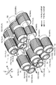
- FIG. 2 is a schematic perspective view illustrating a part of the power transmission device according to at least one embodiment of the present disclosure.
- FIG. 3 is a schematic perspective view illustrating a configuration example of the power transmission device according to the embodiment.
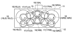
- FIG. 4 is a schematic diagram illustrating a configuration example of a power transmission device according to an embodiment.
- the power transmission device 10 according to at least one embodiment of the present disclosure is configured to transmit the driving force of the motor 14 to one driven shaft 2 (for example, the rolling roll 2A).
- a motor as a rotational force opposite to the one driven shaft 2 with respect to one power transmission path 11 and another driven shaft 2 (for example, a rolling roll 2B) disposed opposite to the one driven shaft.
- a second power transmission path 12 for transmitting 14 driving forces.
- the power transmission device 10 includes a casing 13 that houses the first power transmission path 11 and the second power transmission path 12.
- Each of the first power transmission path 11 and the second power transmission path 12 is provided with only one of them depending on the arrangement of the driven shafts 2 or is in a positional relationship such as up and down or left and right. Or are arranged as follows. At least one of the first power transmission path 11 and the second power transmission path 12 has a first intermediate rotating body 16 that is fixed with respect to the output shaft 15 of the motor 14 and rotated by the driving force of the motor 14. A second intermediate rotating body 17 that is rotated by the first intermediate rotating body 16 and moves along the outer periphery of the first intermediate rotating body 16, and is rotated by the second intermediate rotating body 17 and driven to one or another driven shaft. And a drive shaft 18 for transmitting force. For example, in FIGS.
- each of the first power transmission path 11 and the second power transmission path 12 is 1 shows a configuration example including a first intermediate rotator 16, a second intermediate rotator 17, and a drive shaft 18.
- FIGS. 1 and 2 show the first power transmission path 11 and the second power transmission only on the left side.
- route 12 is shown, and FIG.3 and FIG.4 has shown the structure provided with the said 1st power transmission path
- the output shaft 15, the first intermediate rotator 16, the second intermediate rotator 17, and the drive shaft 18 are supported such that their central axes rotate within the casing 13 via bearings 30.
- the rotating shaft 160LA of the first intermediate rotating body 16 and the rotating shaft 170LA, the rotating shaft 160LB and the rotating shaft 170LB, the rotating shafts 160RA and 170RA, and the rotating shafts 160RB and 170RB of the second intermediate rotating body 17 are respectively bearings. These are connected by a link 20 described later via 30.
- the drive shaft 18 is supported by a frame 19A, which will be described later, via a rotary shaft 180A (180B) and a bearing 30, and the frame 19A is driven by a second drive unit 22 which will be described later, thereby supporting the support 19B. Guided up and down (described later).
- the output shaft 15, the first intermediate rotator 16, the second intermediate rotator 17, and the drive shaft 18 of the motor 14 are connected to the respective rotating shafts 150, Gears that rotate integrally with the rotary shafts are provided on the outer periphery of 160LA, 160LB, 160RA, 160RB, 170LA, 170LB, 180A, and 180B, and are configured to transmit power by meshing with each other via the gears. May be.
- the output shaft 15 of the motor 14, the first intermediate rotating body 16 (a torque receiving unit 16A described later in more detail), the first intermediate rotating body 16 (the second torque transmitting unit 16C described later in more detail) and the first The first intermediate rotator 16 (first intermediate rotator 16D described later in detail), the first intermediate rotator 16 (first torque transmission unit 16B described later in detail), the second intermediate rotator 17, and the second The intermediate rotator 17 and the drive shaft 18 can be configured to transmit rotational torque by being meshed with each other via gears provided on the outer periphery of each.
- the rotation shaft 160LA disposed next to the output shaft 15 (on the left side) is longer than the other rotation shafts in the axial direction, and in order from the side closer to the output shaft 15, the first intermediate rotation body 16 is provided.
- a torque receiving unit 16LA, a first torque transmitting unit 16LB, and a second torque transmitting unit 16LC are provided.
- the rotation shaft 160RA arranged next to the output shaft 15 (on the right side) is longer than the other rotation shafts in the axial direction, and the first intermediate rotation body in order from the one closer to the output shaft 15 respectively.
- a torque receiving unit 16RA, a first torque transmitting unit 16RB, and a second torque transmitting unit 16RC are provided.
- the second intermediate rotator 17 is arranged such that the locus of movement of the axis of the second intermediate rotator 17 is a circular arc centered on the axis of the first intermediate rotator 16. Therefore, a smooth meshing state can be ensured at all times, and the driving force of the motor 14 can be reliably transmitted to the driven shaft 2.
- the second intermediate rotator 17 moves in an arc along the circumferential direction of the first intermediate rotator 16” means that “the second intermediate rotator 17 "Moving to form a circular arc centered on the axis”.
- the first intermediate rotating body 16 is supported so as to rotate so that the rotation center axis thereof maintains a certain distance from the rotation center axis of the output shaft 15.
- the first intermediate rotator 16 is arranged in parallel with the output shaft 15, and the relative positional relationship of the rotation center axes with respect to the output shaft 15 is fixed. You can also.
- the first intermediate rotating body 16 is formed to be longer than the output shaft 15 in the axial direction.
- the outer periphery on one end side close to the output shaft 15 is arranged on the left side in FIG. 4, for example, a torque receiving portion 16A to which torque is transmitted from the output shaft 15.
- the torque receiving unit 16A is a torque receiving unit 16LA
- the torque receiving unit 16A arranged on the right side is a torque receiving unit 16RA.
- the outer periphery in the middle in the longitudinal direction of the first intermediate rotator 16 is a first torque transmission unit 16B (the left side is the first torque transmission unit 16LB) that transmits torque to the second intermediate rotator 17 of the first power transmission path 11.
- the right side is configured as the first torque transmission unit 16RB). Further, the outer periphery of the first intermediate rotator 16 on the other end side that is far from the output shaft 15 is a second torque transmission unit 16 ⁇ / b> C that transmits torque to the second intermediate rotator 17 of the second power transmission path 12. (The left side is the second torque transmission unit 16LC, and the right side is the second torque transmission unit 16RC).
- the first power transmission path 11 and the second power transmission path 12 are the same as the first intermediate rotor 16 in each power transmission path 11, 12.
- the first intermediate rotating body 16 may be shared. If it does in this way, size reduction of the power transmission device 10 can be achieved.
- the torque receivers 16LA and 16RA and the first torque transmitters 16LB and 16RB constitute the first power transmission path 11, and the torque receivers 16LA and 16RA,
- the two torque transmission units 16LC and 16RC and 16LD and 16RD constitute the second power transmission path 12. That is, the first torque transmission units 16LB and 16RB contribute only to the first power transmission path 11 and do not contribute to the second power transmission path 12.
- any one of the first power transmission path 11 and the second power transmission path 12 may include an odd number of first intermediate rotating bodies 16 as compared with the other. 2 to 4, for example, on the second power transmission path 12 side, one more intermediate rotating body 16D (the first intermediate rotating body 16LD on the left side and the first intermediate rotating body 16LD on the right side) than the first power transmission path 11. 1 is a configuration in which one intermediate rotating body 16RD is provided. In this way, the rotational force in the opposite direction can be transmitted to one driven shaft and the other driven shaft, respectively, so that the transported object sandwiched between these one and other driven shafts ( For example, the metal plate 9) can be transported in the same direction.
- the second intermediate rotator 17 (the second intermediate rotator 17L on the left side and the second intermediate rotator 17R on the right side) maintains its rotation center axis at a constant distance from the rotation center axis of the first intermediate rotator 16. It is supported so that it may rotate.
- the second intermediate rotator 17 maintains the axial distance and parallel positional relationship with the first intermediate rotator 16, and does not slip with the outer periphery of the first intermediate rotator 16 (for example, due to gear meshing or friction). )
- a movable gear for example.
- the rotation axis of the drive shaft 18 is arranged in parallel with the rotation axis of the driven shaft 2 (see FIG. 1).
- the rotation center axis of the drive shaft 18 and the rotation center axis of the driven shaft 2 may be arranged coaxially, for example.
- the drive shaft 18 is configured to be connected to the driven shaft 2 so that the driven shaft 2 can move following the movement of the driven shaft 2 in a direction perpendicular to the axial direction. In some embodiments, for example, as shown in FIGS. 1 to 4, when the power transmission device 10 includes both the first power transmission path 11 and the second power transmission path 12, the distance between the axes of the driven shaft 2 is reduced.
- the drive shafts 18 of the respective power transmission paths are configured such that the distance between the axes is changed while maintaining a parallel positional relationship with each other.
- the drive gear 18A moves upward.
- the drive gear 18A moves downward.
- the drive shaft 18 can move in a direction perpendicular to the axial direction of the drive shaft 18 according to the movement of the second intermediate rotator 17 around the first intermediate rotator 16. It is configured.
- the first power transmission path 11 (upper side) and the second power transmission path 12 (lower side) may be provided on either the left or right side (for example, only the left side in FIG. 2).
- the first power transmission path 11 and the second power transmission path 12 may be provided on both the left and right as viewed from the axial direction.
- the second intermediate rotating body 17 moves (for example, in an arc shape) along the outer periphery of the first intermediate rotating body 16 whose axial center position is fixed with respect to the output shaft 15 of the motor.
- the drive shaft 18 and a driven shaft connected to the drive shaft 18 can be suppressed, high efficiency can be achieved by following the distance between the axes of the driven shafts while suppressing the increase in the length of the shaft coupling 5 and the contact area.
- Torque can be transmitted to
- the area of the meshing surface or friction surface between the drive shaft 18 and the driven shaft that contributes to power transmission can be increased, for example, the diameter of the shaft coupling 5 when transmitting the same torque is reduced. Can do.
- the load capacity can be increased.
- At least one of the first power transmission path 11 or the second power transmission path 12 is connected to the output shaft 15 of the motor 14.
- the second power transmission path 12 (for example, the lower side) includes a pair of left and right first intermediate rotating bodies 16 (16 ⁇ / b> L and 16 ⁇ / b> R) as viewed from the axial direction of the output shaft 15, and a pair of left and right pairs.
- the structure including the second intermediate rotator 17 (17L, 17R) is shown, only the first power transmission path 11 has two pairs of left and right first intermediate rotators 16 (16L, 16R) and a pair of left and right first rotators. 2 intermediate rotating bodies 17 (17L, 17R) may be included.
- the driving force of the motor 14 is transmitted by a pair, that is, a plurality of rotating bodies (the first intermediate rotating bodies 16L and 16R or the second intermediate rotating bodies 17L and 17R).
- the diameter of the rotating body can be reduced as compared with the case of transmitting by the body. Therefore, the size of the power transmission device 10 can be reduced.
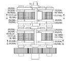
- FIG. 5A is a schematic diagram (plan view) illustrating a configuration example of a power transmission device according to an embodiment.
- FIG. 5B is a schematic diagram (side view) showing a configuration example of a power transmission device according to an embodiment.
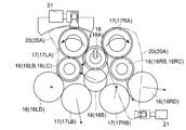
- FIG. 6A is a view showing a cross section AA of FIG. 5A, and is a schematic view showing a (first) power transmission path arranged on the upper side.
- 6B is a diagram showing a BB cross section of FIG. 5A, and is a schematic diagram showing a (second) power transmission path arranged on the lower side.
- FIG. 7 is a schematic side view showing a configuration example of the power transmission device according to the embodiment.
- FIG. 8A is a schematic view showing a CC cross section in FIG.
- FIG. 8B is a schematic diagram showing a DD cross section in FIG. 7 and shows a driving force moving mechanism in the (second) power transmission path arranged on the lower side.
- the first intermediate rotator 16 and the second intermediate rotator 17 may be arranged symmetrically with the drive shaft 18 in between. . That is, the first intermediate rotator 16 may be disposed at the same distance from the drive shaft 18 with the drive shaft 18 interposed therebetween, and the second intermediate rotator 17 may be disposed with the drive shaft 18 interposed therebetween. 18 may be arranged at the same distance from each other. As described above, the first intermediate rotator 16 and the second intermediate rotator 17 are arranged symmetrically with the drive shaft 18 interposed therebetween, so that power that can be reduced in size while suppressing vibration during power transmission.
- a transmission device 10 can be provided.
- the drive shaft 18 configures the first power transmission path 11.
- a first drive shaft (drive gear) 18A that moves in the first movement direction in accordance with the movement of the second intermediate rotators 17LA and 17LB around the first intermediate rotators 16LB and 16RB of the first power transmission path 11.
- a second drive shaft (drive gear) 18B that moves in the second moving direction that is the direction.
- the first drive shaft 18A and the second drive shaft 18B are moved in the first movement direction and the second movement direction, which are opposite to each other, and thus are coupled to the first drive shaft 18A.
- One driven shaft 2A and the other driven shaft 2B connected to the second driving shaft 18B can be moved so that the respective driven shafts 2A and 2B are separated from each other by changing the distance between them. .
- the first drive shaft 18A is connected to the second intermediate rotating body 17 in the first power transmission path 11.
- (17LA, 17RA) rotates around the axis of the first intermediate rotator 16 (16LB, 16RB) in either the clockwise direction or the counterclockwise direction as viewed in the axial direction, It may be configured to move.
- the second drive shaft 18B is configured so that the second intermediate rotating body 17 (17LB, 17RB) is centered on the axis of the first intermediate rotating body 16 (16LD, 16RD) in the second power transmission path 12. It may be configured to move in the second movement direction when rotated in the other direction, either clockwise or counterclockwise when viewed.
- the first drive shaft moves in the first movement direction when the second intermediate rotating body of the first power transmission path rotates in either one of the clockwise direction and the counterclockwise direction as viewed in the axial direction.
- the second drive shaft moves in the second movement direction when the second intermediate rotating body of the second power transmission path rotates in the other direction, either clockwise or counterclockwise, when viewed in the axial direction. That is, in the same axial direction view, the second intermediate rotator of the first power transmission path and the second intermediate rotator of the second power transmission path are rotated in different directions around the axis of the first intermediate rotator.
- the first drive shaft and the second drive shaft can be moved in different directions.
- the second intermediate rotator of the first power transmission path and the second intermediate rotator of the second power transmission path rotate in the same direction around the axis of the first intermediate rotator.
- the first drive shaft and the second drive shaft may be moved in the same direction.
- the drive shaft 18 (first drive shaft 18 ⁇ / b> A) of the first power transmission path 11 is a second drive in the axial direction.
- the second drive shaft 18B may be disposed so as not to overlap with the second drive shaft 18B in a plan view. That is, the drive shaft 18 of the first power transmission path 11 and the drive shaft 18 of the second power transmission path 12 can be arranged so as not to overlap each other in plan view (see, for example, FIG. 1).
- the drive shaft 18 of the first power transmission path 11 and the drive shaft 18 of the second power transmission path 12 are arranged so as to be displaced from each other in a side view, and follow the inter-axis distance of the driven shaft 2.
- the shaft member that connects one of the drive shafts 18 and the driven shaft 2 and the other drive shaft 18 do not interfere (or overlap). Can be placed.
- the drive shafts 18 of the first power transmission path 11 and the second power transmission path 12 are displaced in the axial direction and do not interfere with each other. Interference of the drive shaft 18 can be avoided. Therefore, it is possible to provide the power transmission device 10 that reliably transmits torque while smoothly following the change in the inter-axis distance of the driven shaft.
- both the first power transmission path 11 and the second power transmission path 12 are connected to the first intermediate rotating body 16, the second intermediate rotating body 17, and the drive.
- a shaft 18 may be included. That is, the first power transmission path 11 and the second power transmission path 12 are each configured to transmit power to the pair of driven shafts 2, and each has a drive shaft 18 that is independently provided.
- the drive shaft 18 may be configured to be movable in a direction perpendicular to the axial direction of the drive shaft 18. As described above, according to the configuration in which the drive shafts 18 of the first power transmission path 11 and the second power transmission path 12 are moved in the direction perpendicular to the axial direction, the distance between the axes of the driven shafts is changed. It is possible to smoothly follow the displacement of any driven shaft. In addition, since the two driven shafts 2 can be driven by one motor 14, the power transmission device 10 can be reduced in size.
- the distance between the second intermediate rotating body 17 and the first intermediate rotating body 16 is restricted at least at a part of the rotation axis so that the distance from the first intermediate rotating body 16 is kept constant. Or may be supported so as to be biased toward the first intermediate rotating body 16.
- the second intermediate rotator 17 is supported so that the distance from the drive shaft 18 is constrained in at least a part of the rotation shaft so that the distance from the drive shaft 18 is kept constant. Alternatively, it may be supported so as to be biased toward the drive shaft 18. Examples of the configuration for constraining the distance include a guide groove for guiding each shaft and a link 20 described later.
- the power transmission device 10 includes a part or all of the first intermediate rotator 16, the second intermediate rotator 17, and the drive shaft 18, as illustrated in FIGS. 4 to 6B. 20 may be connected to each other.
- the power transmission device 10 may include, for example, a link 20 ⁇ / b> A that maintains a constant center-to-axis distance between the first intermediate rotator 16 and the second intermediate rotator 17.
- the links 20A may be provided at both ends of the torque receiving portion 16A, both ends of the first torque transmitting portion 16B, and both ends of the second torque transmitting portion 16C in the axial direction. .
- the link 20 ⁇ / b> A may be configured such that the second intermediate rotator 17 side swings about the axis (rotation center axis) of the first intermediate rotator 16.
- the power transmission device 10 may include a link 20B that maintains a constant distance between the axes of the second intermediate rotating body 17 and the drive shaft 18 as shown in FIG. 5A, for example.
- the link 20B may be provided at both ends of the second intermediate rotating body 17 and the drive shaft 18 in the axial direction, for example, as shown in FIG. 5A.
- the link 20 (20A) is kept constant by the link 20 (20A). Therefore, for example, as shown in FIGS.
- the second intermediate is moved on the arc of the first intermediate rotating body 16 with the movement of the drive shaft 18 following the change in the inter-axis distance of the driven shaft 2. Even if the rotator 17 moves, the power can be reliably transmitted without slipping or idling between the intermediate rotators 16 and 17. Further, the distance between the axial centers of the second intermediate rotating body 17 and the drive shaft 18 is maintained constant by the link 20 (20B). Therefore, even if the drive shaft 18 moves on the arc of the second intermediate rotator 17 with the movement of the drive shaft 18 following the change in the inter-axis distance of the driven shaft 2, slipping or idling occurs between them. Power can be reliably transmitted without being generated.
- the power transmission device 10 uses the second intermediate rotator 17 as an operating point with the axis of the first intermediate rotator 16 as a fulcrum, as exemplified in FIGS. 4, 6A and 6B.
- a first drive unit 21 that is connected to the power point of the link 20 (20A) held by the second drive unit 20 and applies a swinging force that moves the second intermediate rotating body 17 along the outer periphery of the first intermediate rotating body 16.
- the 1st drive part 21 may be constituted by actuators, such as an electromagnetic solenoid, a motor, or a hydraulic cylinder, for example.
- the first drive unit 21 is configured to maintain the relative positional relationship between the driven shaft 2 and the drive shaft 18 connected thereto in accordance with the movement of the driven shaft 2. 17 can be controlled to move on the arc of the first intermediate rotator 16.
- the first drive unit 21 that can swing the second intermediate rotator 17 in the first power transmission path 11 around the first intermediate rotator 16 is arranged as shown in FIG. 6A, for example.
- middle rotary body 17 (17LA) of the left side in the 1st power transmission path 11 is the 1st intermediate
- the link 20A is swung around the first intermediate rotator 16 (16LA), and the second intermediate rotator 17 (17LA) moves.
- the first drive unit 21 that swings the second intermediate rotator 17 (17RA) on the right side in the first power transmission path 11 includes the first intermediate rotator 16 (16RA) and the second intermediate rotator. 17 (17RA) is connected to the lower part of the link 20A (in other words, on the side opposite to the operating point with respect to the fulcrum of the link 20A), and the output shaft of the first drive unit 21 moves in the horizontal direction.
- the link 20A is swung around the first intermediate rotator 16 (16RA), and the second intermediate rotator 17 (17RA) moves.
- the links 20A arranged on the right side and the left side can be formed such that the fulcrum, the force point, and the action point are arranged in a straight line.
- the first drive unit 21 that can swing the second intermediate rotator 17 (17LB, 17RB) around the first intermediate rotator 16 (16LD, 16RD) in the second power transmission path 12 is shown in FIG. 6B, for example.
- the drive unit 21 has an upper point of the link 20A connecting the first intermediate rotating body 16 (16LD, 16RD) and the second intermediate rotating body 17 (17LB, 17RB) (in other words, an operating point with respect to the fulcrum of the link 20A).
- the link 20A When the output shaft of the first drive unit 21 moves in the horizontal direction, the link 20A is swung around the first intermediate rotating body 16 (16LD, 16RD), The second intermediate rotator 17 (17LB, 17RB) moves.
- FIG. 6B when the first drive units 21 are arranged with the output shafts directed in the same direction, the advance / retreat of the output shafts of the first drive units 21 can be controlled in opposite phases.
- omitted when each 1st drive part 21 is arrange
- the links 20A arranged on the right side and the left side can be formed such that the fulcrum, the force point, and the action point are arranged in an L shape.
- the first intermediate rotating body 17 can be actively moved along the arc of the first intermediate rotating body 16 by the first driving unit 21.
- the rolling roll 2 that is the driven shaft It is possible to reduce the load on the drive shaft 18 due to the change of the inter-axis distance.
- the power transmission device 10 may include a second drive unit 22 for moving the drive shaft 18 in a direction perpendicular to the axial direction as shown in FIGS. 4, 7, 8 ⁇ / b> A, and 8 ⁇ / b> B, for example.
- the 2nd drive part 22 may be comprised by actuators, such as an electromagnetic solenoid, a motor, or a hydraulic cylinder, for example.
- the second drive unit 22 can be controlled in accordance with the movement of the driven shaft 2 so that the relative positional relationship between the driven shaft 2 and the drive shaft 18 connected thereto is maintained.
- the second drive unit 22 that moves the drive shaft 18 in the first power transmission path 11 in a direction perpendicular to the axial direction of the drive shaft 18 is, for example, as shown in FIG. 8A. Be placed.
- the second drive unit 22 is connected to the lower part of the support 19B that guides the frame 19A that holds the bearing 30 of the drive shaft 18 with the output shaft facing upward, and the output of the second drive unit 22 As the shaft moves in the vertical direction, the drive shaft 18 moves in the vertical direction.
- the second drive unit 22 that moves the drive shaft 18 in the second power transmission path 12 in a direction perpendicular to the axial direction of the drive shaft 18 (for example, the vertical direction) is arranged as shown in FIG. 8B, for example.
- the second drive unit 22 is connected to the upper part of the support 19 ⁇ / b> B that guides the frame 19 ⁇ / b> A that holds the bearing 30 of the drive shaft 18, with the output shaft directed downward, and the output of the second drive unit 22.
- the drive shaft 18 moves in the vertical direction.
- the drive shaft 18 is moved in the direction perpendicular to the axial direction by the second drive unit 22, for example, the change of the inter-axis distance of the driven shaft and the first drive shaft 18 by the second drive unit 22.
- the load on the drive shaft 18 due to the change in the inter-axis distance of the driven shaft can be reduced.
- the rolling mill 1 is provided with the 3rd drive part 23 which provides the motive power which changes the axial distance of a pair of rolling roll 2.
- the 3rd drive part 23 may be comprised by actuators, such as an electromagnetic solenoid, a motor, or a hydraulic cylinder, for example.
- actuators such as an electromagnetic solenoid, a motor, or a hydraulic cylinder, for example.
- at least the 2nd drive part 22 and the 3rd drive part 23 may interlock
- the power transmission device 10 may further include the first drive unit 21 described above, and the first drive unit 21, the second drive unit 22, and the third drive unit 23 are configured to smoothly interlock with each other. It may be.
- the second drive unit 22 that moves at least the drive shaft 18 in the direction perpendicular to the axial direction and the third drive unit 23 that applies power to change the inter-axis distance between the pair of rolling rolls 2 are interlocked. With this configuration, it is possible to maintain the same distance between the axes while suppressing the load on the pair of rolling rolls 2 and the pair of drive shafts 18 due to the change in the distance between the axes. You can plan.
- FIG. 9 is a schematic perspective view illustrating a configuration example of a power transmission device according to another embodiment.
- the output shaft 15, the first intermediate rotator 16, the second intermediate rotator 17, or the drive shaft 18 of the motor 14 may be configured to include a roller, for example as illustrated in a non-limiting manner in FIG. 9. That is, the output shaft 15, the first intermediate rotator 16, the second intermediate rotator 17, and the drive shaft 18 may be configured to transmit rotational torque by the frictional force of each peripheral surface.
- the output shaft 15, the first intermediate rotating body 16, the second intermediate rotating body 17 or the drive shaft 18 of the motor 14 includes the rollers, it is possible to reduce vibration and operating noise during operation. it can.
- the output shaft 15, the first intermediate rotator 16, the second intermediate rotator 17, and the drive shaft 18 described above can reduce the backlash compared to the configuration including gears, the transmission loss of power can be reduced. Can do. Moreover, since it is not necessary to process the gear teeth, man-hours and costs for manufacturing can be reduced.
- the present invention is not limited to the above-described embodiments, and includes forms obtained by changing the above-described embodiments and forms obtained by combining these forms.
- the driving device that drives the rolling roll 2 of the rolling mill 1 is illustrated as the power transmission device 10, but the power transmission device 10 of the present invention is not limited to this.
- the power transmission device 10 may be a drive device for driving a positive displacement pump.
- the positive displacement pump for example, a vane pump or a geared pump may be employed.
- one of the first power transmission path 11 and the second power transmission path 12 may include the first intermediate rotator 16, the second intermediate rotator 17, and the drive shaft 18.
- first power transmission path 11 disposed on the upper side includes the first intermediate rotator 16, the second intermediate rotator 17, and the drive shaft 18, and the upper drive shaft 18 is configured to move up and down.
- second power transmission path 12 disposed on the lower side may include the first intermediate rotator 16, the second intermediate rotator 17, and the drive shaft 18. In this case, the lower drive shaft Only 18 is configured to move up and down.
- Rolling machine Rolling roll (driven shaft) 5 shaft coupling 5A coupling 9 metal plate 10 power transmission device (rolling roll drive mechanism) 11 First power transmission path 12 Second power transmission path 13 Casing 14 Motor 15 Motor output shaft (input shaft) 16 Intermediate gear (first intermediate rotating body) 17 Auxiliary gear (second intermediate rotating body) 18 Drive gear (output shaft / drive shaft) 20 Link 21 1st drive part 22 2nd drive part 23 3rd drive part g Center distance
Landscapes
- Engineering & Computer Science (AREA)
- General Engineering & Computer Science (AREA)
- Mechanical Engineering (AREA)
- Transmission Devices (AREA)
- Gear Transmission (AREA)
Abstract
動力伝達装置は、モータの駆動力を一の被駆動軸に伝達するための第1動力伝達経路と、上記一の被駆動軸に対向配置された他の被駆動軸にモータの駆動力を伝達するための第2動力伝達経路と、を備えている。第1動力伝達経路又は第2動力伝達経路の少なくとも一方は、モータの出力軸に対して軸心位置が固定されモータの駆動力によって回転される第1中間回転体と、第1中間回転体によって回転され該第1中間回転体の外周に沿って円弧状に移動する第2中間回転体と、第2中間回転体によって回転され一又は他の被駆動軸に駆動力を伝達する駆動軸と、を含む。駆動軸は、第1中間回転体周りの第2中間回転体の移動に応じて、該駆動軸の軸心方向に垂直な方向に移動するように構成されている。
Description
本開示は、動力伝達装置及び圧延機に関する。
従来、対向して配置された2本の圧延ロール間に金属板を挟み、両圧延ロールの回転により金属板を通過させて展伸・圧延を行い板材に加工する圧延機が知られている。
また、圧延機ではないが、例えば、特許文献1には、駆動歯車の軸心位置を、他の歯車軸を中心に回転させ、従動歯車と嵌脱させるターニング装置用歯車が開示されている。
ところで、上記の圧延機においては、板厚の変更やメンテナンスのために2本の圧延ロールの中心間距離を変更する必要がある。一方で、上記2本の圧延ロールの各々に軸継手を介して回転力を付与する歯車装置は、2本の出力軸の軸間距離が一般に固定されている。このため、圧延ロールの軸間距離の変更に追従するべく、ユニバーサルジョイントやギヤカップリング等の軸継手が採用されているが、これらの軸継手の傾き角と伝達トルクとには制約があり、許容値以下の傾き角で確実にトルクを伝達するには軸継手を長軸化する必要が生じる。このような軸継手の長軸化により、振動及び設置面積が増大するとともに、製造、交換等のコストも増加するという問題がある。
この点、特許文献1には、上記のような問題を解決するための具体的な構成について何ら開示されていない。
この点、特許文献1には、上記のような問題を解決するための具体的な構成について何ら開示されていない。
上述した問題に鑑み、本開示の少なくとも一実施形態は、接地面積を抑制しつつ被駆動軸の軸間距離に追従してトルクを伝達する構成を提供することを目的とする。
(1)本開示の少なくとも一実施形態に係る動力伝達装置は、
モータの駆動力を一の被駆動軸に伝達するための第1動力伝達経路と、
前記一の被駆動軸に対向配置された他の被駆動軸に前記モータの駆動力を伝達するための第2動力伝達経路と、を備え、
前記第1動力伝達経路又は前記第2動力伝達経路の少なくとも一方は、
前記モータの出力軸に対して軸心位置が固定され前記モータの駆動力によって回転される第1中間回転体と、
前記第1中間回転体によって回転され該第1中間回転体の外周に沿って移動する第2中間回転体と、
前記第2中間回転体によって回転され前記一又は他の被駆動軸に駆動力を伝達する駆動軸と、を含み、
前記駆動軸は、前記第1中間回転体周りの前記第2中間回転体の移動に応じて、該駆動軸の軸心方向に垂直な方向に移動するように構成されている。
モータの駆動力を一の被駆動軸に伝達するための第1動力伝達経路と、
前記一の被駆動軸に対向配置された他の被駆動軸に前記モータの駆動力を伝達するための第2動力伝達経路と、を備え、
前記第1動力伝達経路又は前記第2動力伝達経路の少なくとも一方は、
前記モータの出力軸に対して軸心位置が固定され前記モータの駆動力によって回転される第1中間回転体と、
前記第1中間回転体によって回転され該第1中間回転体の外周に沿って移動する第2中間回転体と、
前記第2中間回転体によって回転され前記一又は他の被駆動軸に駆動力を伝達する駆動軸と、を含み、
前記駆動軸は、前記第1中間回転体周りの前記第2中間回転体の移動に応じて、該駆動軸の軸心方向に垂直な方向に移動するように構成されている。
上記(1)の構成によれば、モータの出力軸に対して軸心位置が固定された第1中間回転体の外周に沿って第2中間回転体が移動することで、第1動力伝達経路又は第2動力伝達経路の少なくとも一方の駆動軸が軸心方向に垂直な方向に移動する。これにより、駆動軸と該駆動軸に接続される被駆動軸との間のミスアライメントを抑制することができるから、軸継手の長軸化を抑制して接地面積を抑制しつつ、被駆動軸の軸間距離に追従して高効率にトルクを伝達することができる。また、動力伝達に寄与する駆動軸と被駆動軸との噛み合い面又は摩擦面の面積を増大することができるから、例えば、同一のトルクを伝達する際の軸継手の直径を低減することができる。換言すれば、軸継手の径が同一であれば負荷容量を増大することができる。さらに、片あたりや歯面荷重増大による折損を防止するとともに、動力伝達の際の面圧や歯面の滑りを低減することができるため、摩耗を抑制して装置寿命の増大を図ることができる。
(2)幾つかの実施形態では、上記(1)に記載の構成において、
前記動力伝達装置は、前記第2中間回転体の軸心の移動軌跡が前記第1中間回転体の軸心を中心とする円の円弧状になるように構成されていてもよい。
前記動力伝達装置は、前記第2中間回転体の軸心の移動軌跡が前記第1中間回転体の軸心を中心とする円の円弧状になるように構成されていてもよい。
上記(2)の構成によれば、駆動軸又は被駆動軸の上下動に伴い、第2中間回転体の軸心の移動の軌跡が第1中間回転体の軸心を中心とする円弧になるように第2中間回転体が円弧運動するから、常に円滑な噛み合い状態を確保することができるとともに、モータの駆動力を被駆動軸まで確実に伝達することができる。
(3)幾つかの実施形態では、上記(1)又は(2)に記載の構成において、
前記第1動力伝達経路又は前記第2動力伝達経路の少なくとも一方は、
前記モータの前記出力軸を挟んで一方と他方とに配置された少なくとも一対の前記第1中間回転体と、
前記モータの前記出力軸を挟んで前記一方と前記他方とに配置された一対の前記第2中間回転体と、を含んでもよい。
前記第1動力伝達経路又は前記第2動力伝達経路の少なくとも一方は、
前記モータの前記出力軸を挟んで一方と他方とに配置された少なくとも一対の前記第1中間回転体と、
前記モータの前記出力軸を挟んで前記一方と前記他方とに配置された一対の前記第2中間回転体と、を含んでもよい。
上記(3)の構成によれば、モータの駆動力を一対すなわち複数の回転体で伝達することにより、例えば同一のトルクを一つの回転体で伝達する場合に比べて回転体を小径化することができる。よって、動力伝達装置の小型化を図ることができる。
(4)幾つかの実施形態では、上記(3)に記載の構成において、
前記第1中間回転体及び前記第2中間回転体は、前記駆動軸を挟んで対称に配置されてもよい。
前記第1中間回転体及び前記第2中間回転体は、前記駆動軸を挟んで対称に配置されてもよい。
上記(4)の構成によれば、第1中間回転体及び第2中間回転体が駆動軸を挟んで対称に配置されることにより、動力伝達の際の振動を抑制しつつ、小型化できる動力伝達装置を提供することができる。
(5)幾つかの実施形態では、上記(4)に記載の構成において、
前記駆動軸は、
前記第1動力伝達経路を構成するとともに、前記第1動力伝達経路の前記第1中間回転体周りの前記第2中間回転体の移動に応じて第1移動方向に移動する第1駆動軸と、
前記第2動力伝達経路を構成するとともに、前記第2動力伝達経路の前記第1中間回転体周りの前記第2中間回転体の移動に応じて前記第1移動方向と逆向きである第2移動方向に移動する第2駆動軸と、を含んでいてもよい。
前記駆動軸は、
前記第1動力伝達経路を構成するとともに、前記第1動力伝達経路の前記第1中間回転体周りの前記第2中間回転体の移動に応じて第1移動方向に移動する第1駆動軸と、
前記第2動力伝達経路を構成するとともに、前記第2動力伝達経路の前記第1中間回転体周りの前記第2中間回転体の移動に応じて前記第1移動方向と逆向きである第2移動方向に移動する第2駆動軸と、を含んでいてもよい。
上記(5)の構成によれば、第1駆動軸と第2駆動軸とが、それぞれ逆向きである第1移動方向と第2移動方向とに移動されるから、第1駆動軸に連結された一の被駆動軸と第2駆動軸に連結された他の被駆動軸とを、互いの距離が変化して各々の被駆動軸が離接するように移動させることができる。
(6)幾つかの実施形態では、上記(5)に記載の構成において、
前記第1駆動軸は、前記第1動力伝達経路において前記第2中間回転体が前記第1中間回転体の前記軸心を中心として、前記軸心方向視における時計回り又は反時計回りの何れか一方向に回転したときに前記第1移動方向に移動するように構成されており、
前記第2駆動軸は、前記第2動力伝達経路において前記第2中間回転体が前記第1中間回転体の前記軸心を中心として、前記軸心方向視における前記時計回り又は前記反時計回りの何れか他方向に回転したときに前記第2移動方向に移動するように構成されていてもよい。
前記第1駆動軸は、前記第1動力伝達経路において前記第2中間回転体が前記第1中間回転体の前記軸心を中心として、前記軸心方向視における時計回り又は反時計回りの何れか一方向に回転したときに前記第1移動方向に移動するように構成されており、
前記第2駆動軸は、前記第2動力伝達経路において前記第2中間回転体が前記第1中間回転体の前記軸心を中心として、前記軸心方向視における前記時計回り又は前記反時計回りの何れか他方向に回転したときに前記第2移動方向に移動するように構成されていてもよい。
上記(6)の構成によれば、第1動力伝達経路の第2中間回転体が軸心方向視における時計回り又は反時計回りの何れか一方向に回転したときに第1駆動軸が第1移動方向に移動し、上記軸方向視において第2動力伝達経路の第2中間回転体が上記時計回り又は反時計回りの何れか他方向に回転したときに第2駆動軸が第2移動方向に移動する。つまり、同一の軸方向視において、第1動力伝達経路の第2中間回転体と第2動力伝達経路の第2中間回転体とを第1中間回転体の軸心を中心に異なる方向に回転させることで第1駆動軸と第2駆動軸とを異なる方向に移動させることができる。なお、同一の軸方向視において、第1動力伝達経路の第2中間回転体と第2動力伝達経路の第2中間回転体とを第1中間回転体の軸心を中心に同一の方向に回転させることにより、第1駆動軸と第2駆動軸とを同一の方向に移動させることができるようにしてもよい。
(7)幾つかの実施形態では、上記(5)又は(6)に記載の構成において、
前記第1駆動軸は、前記軸心方向において前記第2駆動軸とずれて配置され、平面視にて前記第2駆動軸とオーバーラップしないように配置されてもよい。
前記第1駆動軸は、前記軸心方向において前記第2駆動軸とずれて配置され、平面視にて前記第2駆動軸とオーバーラップしないように配置されてもよい。
上記(7)の構成によれば、第1駆動軸が第2駆動軸と軸心方向にずれて平面視にて第2駆動軸とオーバーラップしないことにより、第1駆動軸及び第2駆動軸がそれぞれ一の被駆動軸及び他の駆動軸に追従することによる両駆動軸の干渉を回避することができる。よって、被駆動軸の軸間距離の変更に円滑に追従しつつ、確実にトルクを伝達する動力伝達装置を提供することができる。
(8)幾つかの実施形態では、上記(1)~(7)の何れか1つに記載の構成において、
前記第1動力伝達経路及び前記第2動力伝達経路の双方が、
前記第1中間回転体、前記第2中間回転体及び前記駆動軸を含んでもよい。
前記第1動力伝達経路及び前記第2動力伝達経路の双方が、
前記第1中間回転体、前記第2中間回転体及び前記駆動軸を含んでもよい。
上記(8)の構成によれば、第1動力伝達経路及び第2動力伝達経路の各々の駆動軸が軸心方向に垂直な方向に移動するように構成される。従って、被駆動軸の軸間距離の変更の際、何れの被駆動軸の変位にも円滑に追従することができる。
(9)幾つかの実施形態では、上記(1)~(8)の何れか一つに記載の構成において、
前記第1中間回転体と当該第1中間回転体により回転される前記第2中間回転体との軸心間距離を一定に保持するリンクを備えていてもよい。
前記第1中間回転体と当該第1中間回転体により回転される前記第2中間回転体との軸心間距離を一定に保持するリンクを備えていてもよい。
上記(9)の構成によれば、リンクにより第1中間回転体と第2中間回転体との軸心間距離が一定に保持される。従って、被駆動軸の軸間距離の変更に追従する駆動軸の移動に伴い、第1中間回転体の円弧上を第2中間回転体が移動しても、両中間回転体の間で滑りや空回りが発生することなく、確実に動力を伝達することができる。
(10)幾つかの実施形態では、上記(9)に記載の構成において、
前記第1中間回転体の軸心を支点として前記第2中間回転体を作用点に保持する前記リンクの力点に接続され、前記第2中間回転体を前記第1中間回転体の円弧に沿って前記第2中間回転体の軸心の移動の軌跡が前記第1中間回転体の前記軸心を中心とする円の円弧状になるように移動させる揺動力を付与する第1駆動部を備えていてもよい。
前記第1中間回転体の軸心を支点として前記第2中間回転体を作用点に保持する前記リンクの力点に接続され、前記第2中間回転体を前記第1中間回転体の円弧に沿って前記第2中間回転体の軸心の移動の軌跡が前記第1中間回転体の前記軸心を中心とする円の円弧状になるように移動させる揺動力を付与する第1駆動部を備えていてもよい。
上記(10)の構成によれば、第1駆動部により、第1中間回転体の円弧に沿って第2中間回転体を能動的に移動させることができる。これにより、例えば、被駆動軸の軸間距離の変更と第1駆動軸による第2中間回転体の移動を同期させた場合は、被駆動軸の軸間距離の変更に伴う駆動軸への負荷を低減することができる。
(11)幾つかの実施形態では、上記(1)~(10)の何れか一つに記載の構成において、
前記駆動軸を前記軸心方向に垂直な方向に移動するための第2駆動部を備えていてもよい。
前記駆動軸を前記軸心方向に垂直な方向に移動するための第2駆動部を備えていてもよい。
上記(11)の構成によれば、第2駆動部により駆動軸が軸心方向に垂直な方向に移動される。これにより、例えば、被駆動軸の軸間距離の変更と第2駆動部による第1駆動軸の移動を同期させた場合は、被駆動軸の軸間距離の変更に伴う駆動軸への負荷を低減することができる。
(12)幾つかの実施形態では、上記(1)~(11)の何れか一つに記載の構成において、
前記モータの前記出力軸、前記第1中間回転体、前記第2中間回転体又は前記駆動軸は、各々の外周にギヤを含み、前記ギヤを介して互いが噛み合うことで動力を伝達するように構成されていてもよい。
前記モータの前記出力軸、前記第1中間回転体、前記第2中間回転体又は前記駆動軸は、各々の外周にギヤを含み、前記ギヤを介して互いが噛み合うことで動力を伝達するように構成されていてもよい。
上記(12)の構成によれば、モータの出力軸、第1中間回転体、第2中間回転体又は駆動軸がギヤを含んで構成される。よって、モータの駆動力を被駆動軸まで確実に伝達することができる。
(13)幾つかの実施形態では、上記(1)~(11)の何れか一つに記載の構成において、
前記モータの前記出力軸、前記第1中間回転体、前記第2中間回転体又は前記駆動軸はローラを含んでもよい。
前記モータの前記出力軸、前記第1中間回転体、前記第2中間回転体又は前記駆動軸はローラを含んでもよい。
上記(13)の構成によれば、モータの出力軸、第1中間回転体、第2中間回転体又は駆動軸がローラを含んで構成される。これにより、動作時における振動や動作音の低減を図ることができる。
(14)本開示の少なくとも一実施形態に係る圧延機は、
上記(1)~(12)の何れか一つに記載の動力伝達装置と、
前記動力伝達装置の前記駆動軸により回転される前記一及び他の被駆動軸と、を備え、
前記一及び他の被駆動軸は、互いの軸間距離が可変な一対の圧延ロールを含む。
上記(1)~(12)の何れか一つに記載の動力伝達装置と、
前記動力伝達装置の前記駆動軸により回転される前記一及び他の被駆動軸と、を備え、
前記一及び他の被駆動軸は、互いの軸間距離が可変な一対の圧延ロールを含む。
上記(14)の構成によれば、上記(1)で述べたように、駆動軸と被駆動軸との間のミスアライメントを抑制することができ、軸継手の長軸化を抑制して接地面積を抑制しつつ、被駆動軸の軸間距離に追従して高効率にトルクを伝達し得る動力伝達装置を備えた圧延機を得ることができる。
(15)幾つかの実施形態では、上記(14)に記載の構成において、
前記圧延機は、
前記一対の圧延ロールの前記軸間距離を変更する動力を付与する第3駆動部を備え、
少なくとも前記駆動軸を前記軸心方向に垂直な方向に移動するための前記駆動部及び前記第3駆動部が連動することで前記一対の圧延ロールと前記一対の駆動軸とがそれぞれ同一の軸間距離を維持するように構成されていてもよい。
前記圧延機は、
前記一対の圧延ロールの前記軸間距離を変更する動力を付与する第3駆動部を備え、
少なくとも前記駆動軸を前記軸心方向に垂直な方向に移動するための前記駆動部及び前記第3駆動部が連動することで前記一対の圧延ロールと前記一対の駆動軸とがそれぞれ同一の軸間距離を維持するように構成されていてもよい。
上記(15)の構成によれば、少なくとも駆動軸を軸心方向に垂直な方向に移動する駆動部(例えば第2駆動部)と、一対の圧延ロールの軸間距離を変更する動力を付与する第3駆動部とが連動することにより、軸間距離の変更に伴う一対の圧延ロールと一対の駆動軸との負荷を抑制しつつ、各々の軸間距離を同一に維持することができるから、装置寿命の延長を図ることができる。
本開示の少なくとも一実施形態によれば、接地面積を抑制しつつ被駆動軸の軸間距離に追従してトルクを伝達する構成を提供することができる。
以下、添付図面に従って本発明の例示的な実施形態について説明する。ただし、以下に示す幾つかの実施形態に記載された構成部品の寸法、材質、形状、その相対的配置等は、特定的な記載がない限り本発明の範囲をこれに限定する趣旨ではなく、単なる説明例にすぎない。
例えば、「ある方向に」、「ある方向に沿って」、「平行」、「直交」、「中心」、「同心」或いは「同軸」等の相対的或いは絶対的な配置を表す表現は、厳密にそのような配置を表すのみならず、公差、若しくは、同じ機能が得られる程度の角度や距離をもって相対的に変位している状態も表すものとする。
また例えば、四角形状や円筒形状等の形状を表す表現は、幾何学的に厳密な意味での四角形状や円筒形状等の形状を表すのみならず、同じ効果が得られる範囲で、凹凸部や面取り部等を含む形状も表すものとする。
一方、一の構成要素を「備える」、「具える」、「具備する」、「含む」、又は、「有する」という表現は、他の構成要素の存在を除外する排他的な表現ではない。
例えば、「ある方向に」、「ある方向に沿って」、「平行」、「直交」、「中心」、「同心」或いは「同軸」等の相対的或いは絶対的な配置を表す表現は、厳密にそのような配置を表すのみならず、公差、若しくは、同じ機能が得られる程度の角度や距離をもって相対的に変位している状態も表すものとする。
また例えば、四角形状や円筒形状等の形状を表す表現は、幾何学的に厳密な意味での四角形状や円筒形状等の形状を表すのみならず、同じ効果が得られる範囲で、凹凸部や面取り部等を含む形状も表すものとする。
一方、一の構成要素を「備える」、「具える」、「具備する」、「含む」、又は、「有する」という表現は、他の構成要素の存在を除外する排他的な表現ではない。
図1は本開示の少なくとも一実施形態に係る圧延機の構成例を示す概略図である。
図1に非限定的に例示するように、本開示の少なくとも一実施形態に係る圧延機1は、本開示の何れかの実施形態に係る動力伝達装置10と、動力伝達装置10の駆動軸18により回転される一の被駆動軸及び他の被駆動軸としての一対の圧延ロール2(2A、2B)と、を備えている。また、圧延機1は、一対の圧延ロール2の軸間距離を変更する動力を付与する駆動部(例えば後述する第3駆動部23)を備えている。
一対の圧延ロール2は、例えば図1に示すように、間隔を隔てて互いが平行に配置されるとともに、互いの軸間距離g(例えば軸中心間距離又は外周間距離)が可変に構成されている。一対の圧延ロール2は、例えば両者の間に金属板9を挟み、各々の圧延ロール2が互いに逆向きに回転することにより金属板9を通過させて展伸・圧延を行い、板材に加工するようになっている。
かかる動力伝達装置10は、後述の通り、駆動軸18と被駆動軸(例えば圧延ロール2)との間のミスアライメントを抑制可能に構成されており、軸継手5の長軸化を抑制して接地面積を抑制しつつ、被駆動軸の軸間距離に追従して高効率にトルクを伝達し得る動力伝達装置10を備えた圧延機1を得ることができる。
図1に非限定的に例示するように、本開示の少なくとも一実施形態に係る圧延機1は、本開示の何れかの実施形態に係る動力伝達装置10と、動力伝達装置10の駆動軸18により回転される一の被駆動軸及び他の被駆動軸としての一対の圧延ロール2(2A、2B)と、を備えている。また、圧延機1は、一対の圧延ロール2の軸間距離を変更する動力を付与する駆動部(例えば後述する第3駆動部23)を備えている。
一対の圧延ロール2は、例えば図1に示すように、間隔を隔てて互いが平行に配置されるとともに、互いの軸間距離g(例えば軸中心間距離又は外周間距離)が可変に構成されている。一対の圧延ロール2は、例えば両者の間に金属板9を挟み、各々の圧延ロール2が互いに逆向きに回転することにより金属板9を通過させて展伸・圧延を行い、板材に加工するようになっている。
かかる動力伝達装置10は、後述の通り、駆動軸18と被駆動軸(例えば圧延ロール2)との間のミスアライメントを抑制可能に構成されており、軸継手5の長軸化を抑制して接地面積を抑制しつつ、被駆動軸の軸間距離に追従して高効率にトルクを伝達し得る動力伝達装置10を備えた圧延機1を得ることができる。
続いて、本開示の少なくとも一実施形態に係る動力伝達装置10について説明する。
図2は本開示の少なくとも一実施形態に係る動力伝達装置の一部を示す概略斜視図である。図3は一実施形態に係る動力伝達装置の構成例を示す概略斜視図である。図4は一実施形態に係る動力伝達装置の構成例を示す概略図である。
図1~図4に例示するように、本開示の少なくとも一実施形態に係る動力伝達装置10は、モータ14の駆動力を一の被駆動軸2(例えば圧延ロール2A)に伝達するための第1動力伝達経路11と、上記一の被駆動軸に対向配置された他の被駆動軸2(例えば圧延ロール2B)に対して、上記一の被駆動軸2とは逆向きの回転力としてモータ14の駆動力を伝達するための第2動力伝達経路12と、を備えている。また、動力伝達装置10は、上記第1動力伝達経路11及び第2動力伝達経路12を収容するケーシング13を備えている。
図2は本開示の少なくとも一実施形態に係る動力伝達装置の一部を示す概略斜視図である。図3は一実施形態に係る動力伝達装置の構成例を示す概略斜視図である。図4は一実施形態に係る動力伝達装置の構成例を示す概略図である。
図1~図4に例示するように、本開示の少なくとも一実施形態に係る動力伝達装置10は、モータ14の駆動力を一の被駆動軸2(例えば圧延ロール2A)に伝達するための第1動力伝達経路11と、上記一の被駆動軸に対向配置された他の被駆動軸2(例えば圧延ロール2B)に対して、上記一の被駆動軸2とは逆向きの回転力としてモータ14の駆動力を伝達するための第2動力伝達経路12と、を備えている。また、動力伝達装置10は、上記第1動力伝達経路11及び第2動力伝達経路12を収容するケーシング13を備えている。
第1動力伝達経路11及び第2動力伝達経路12の各々は、各々の被駆動軸2の配置に応じて何れか一方のみが設けられたり、或いは互いが例えば上下又は左右等の位置関係となるように配置されたりする。
かかる第1動力伝達経路11又は第2動力伝達経路12の少なくとも一方は、モータ14の出力軸15に対して軸心位置が固定されモータ14の駆動力によって回転される第1中間回転体16と、第1中間回転体16によって回転され該第1中間回転体16の外周に沿って移動する第2中間回転体17と、第2中間回転体17によって回転され一又は他の被駆動軸に駆動力を伝達する駆動軸18と、を含んで構成される。
例えば、図1~図4は、動力伝達装置10が第1動力伝達経路11及び第2動力伝達経路12を備えた構成において、第1動力伝達経路11及び第2動力伝達経路12の各々が、第1中間回転体16、第2中間回転体17及び駆動軸18を含む構成例を示しており、このうち図1及び図2は、左側にのみ上記第1動力伝達経路11及び第2動力伝達経路12を備えた構成を示し、図3及び図4は、左右に上記第1動力伝達経路11及び第2動力伝達経路12を備えた構成を示している。
出力軸15、第1中間回転体16、第2中間回転体17及び駆動軸18は、各々の中心軸が軸受30を介してケーシング13内で回転するように支持されている。詳細には、第1中間回転体16の回転軸160LAと第2中間回転体17の回転軸170LA,回転軸160LBと回転軸170LB,回転軸160RAと170RA、及び回転軸160RBと170RBは、それぞれ軸受30を介して後述するリンク20により連結されている。また、駆動軸18は、回転軸180A(180B)及び軸受30を介して後述するフレーム19Aに支持されており、該フレーム19Aが、後述する第2駆動部22に駆動されることにより支持体19B(後述)に沿って上下に案内されるようになっている。
かかる第1動力伝達経路11又は第2動力伝達経路12の少なくとも一方は、モータ14の出力軸15に対して軸心位置が固定されモータ14の駆動力によって回転される第1中間回転体16と、第1中間回転体16によって回転され該第1中間回転体16の外周に沿って移動する第2中間回転体17と、第2中間回転体17によって回転され一又は他の被駆動軸に駆動力を伝達する駆動軸18と、を含んで構成される。
例えば、図1~図4は、動力伝達装置10が第1動力伝達経路11及び第2動力伝達経路12を備えた構成において、第1動力伝達経路11及び第2動力伝達経路12の各々が、第1中間回転体16、第2中間回転体17及び駆動軸18を含む構成例を示しており、このうち図1及び図2は、左側にのみ上記第1動力伝達経路11及び第2動力伝達経路12を備えた構成を示し、図3及び図4は、左右に上記第1動力伝達経路11及び第2動力伝達経路12を備えた構成を示している。
出力軸15、第1中間回転体16、第2中間回転体17及び駆動軸18は、各々の中心軸が軸受30を介してケーシング13内で回転するように支持されている。詳細には、第1中間回転体16の回転軸160LAと第2中間回転体17の回転軸170LA,回転軸160LBと回転軸170LB,回転軸160RAと170RA、及び回転軸160RBと170RBは、それぞれ軸受30を介して後述するリンク20により連結されている。また、駆動軸18は、回転軸180A(180B)及び軸受30を介して後述するフレーム19Aに支持されており、該フレーム19Aが、後述する第2駆動部22に駆動されることにより支持体19B(後述)に沿って上下に案内されるようになっている。
幾つかの実施形態では、例えば図2及び図3に示すように、モータ14の出力軸15、第1中間回転体16、第2中間回転体17及び駆動軸18は、各々の回転軸150、160LA,160LB,160RA,160RB,170LA,170LB,180A,180Bの外周に各回転軸と一体に回転するギヤが設けられ、該ギヤを介して互いが噛み合うことで動力を伝達するように構成されていてもよい。つまり、モータ14の出力軸15と第1中間回転体16(より詳細には後述するトルク受領部16A)、第1中間回転体16(より詳細には後述する第2トルク伝達部16C)と第1中間回転体16(より詳細には後述する第1中間回転体16D)、第1中間回転体16(より詳細には後述する第1トルク伝達部16B)と第2中間回転体17、第2中間回転体17と駆動軸18は、各々の外周に設けられたギヤを介して噛合されることにより、回転トルクを伝達するように構成され得る。なお、出力軸15の隣(左側)に配置される回転軸160LAは、軸心方向において他の回転軸より長尺であるとともに、出力軸15に近い方から順に、それぞれ第1中間回転体16としてのトルク受領部16LA、第1トルク伝達部16LB及び第2トルク伝達部16LCとが設けられている。同様に、出力軸15の隣(右側)に配置される回転軸160RAは、軸心方向において他の回転軸より長尺であるとともに、出力軸15に近い方から順に、それぞれ第1中間回転体16としてのトルク受領部16RA、第1トルク伝達部16RB及び第2トルク伝達部16RCとが設けられている。
このように、モータ14の出力軸15、第1中間回転体16、第2中間回転体17及び駆動軸18の外周がギヤで構成された場合、駆動軸18又は被駆動軸2の上下動に伴う歯車位置の変化に対応して、第2中間回転体17の軸心の移動の軌跡が第1中間回転体16の軸心を中心とする円の円弧になるように第2中間回転体17が円弧運動するから、常に円滑な噛み合い状態を確保することができるとともに、モータ14の駆動力を被駆動軸2まで確実に伝達することができる。なお、「第2中間回転体17が、該第1中間回転体16の周方向に沿って円弧状に移動する」ことは、「第2中間回転体17が、該第1中間回転体16の軸心を中心とする円の円弧になるように移動する」ことを含む。
このように、モータ14の出力軸15、第1中間回転体16、第2中間回転体17及び駆動軸18の外周がギヤで構成された場合、駆動軸18又は被駆動軸2の上下動に伴う歯車位置の変化に対応して、第2中間回転体17の軸心の移動の軌跡が第1中間回転体16の軸心を中心とする円の円弧になるように第2中間回転体17が円弧運動するから、常に円滑な噛み合い状態を確保することができるとともに、モータ14の駆動力を被駆動軸2まで確実に伝達することができる。なお、「第2中間回転体17が、該第1中間回転体16の周方向に沿って円弧状に移動する」ことは、「第2中間回転体17が、該第1中間回転体16の軸心を中心とする円の円弧になるように移動する」ことを含む。
第1中間回転体16は、その回転中心軸が出力軸15の回転中心軸と一定の距離を維持するようにして回転するように支持されている。この第1中間回転体16は、出力軸15と平行に配置されるとともに、該出力軸15に対して互いの回転中心軸の相対的な位置関係が固定されており、例えば固定ギヤと称することもできる。
図2及び図3に示すように、第1中間回転体16は、軸方向において出力軸15よりも長尺に形成されている。かかる第1中間回転体16は、出力軸15に近接する一端部側の外周が、該出力軸15からトルクを伝達されるトルク受領部16A(より詳細には、例えば図4における左側に配置されているトルク受領部16Aをトルク受領部16LA、右側に配置されているトルク受領部16Aをトルク受領部16RAとする。以下同様)として構成されている。また、第1中間回転体16における長手方向の中間の外周は、第1動力伝達経路11の第2中間回転体17にトルクを伝達する第1トルク伝達部16B(左側を第1トルク伝達部16LB、右側を第1トルク伝達部16RBとする)として構成されている。さらに、第1中間回転体16における、出力軸15からの距離が遠い他端部側の外周は、第2動力伝達経路12の第2中間回転体17にトルクを伝達する第2トルク伝達部16C(左側を第2トルク伝達部16LC、右側を第2トルク伝達部16RCとする)として構成されている。
幾つかの実施形態では、例えば図1~図4に示すように、第1動力伝達経路11及び第2動力伝達経路12は、各々の動力伝達経路11、12における第1中間回転体16として同一の第1中間回転体16を共有するように構成されていてもよい。このようにすれば、動力伝達装置10の小型化を図ることができる。
なお、上述した複数の第1中間回転体16のうち、トルク受領部16LA,16RA、及び第1トルク伝達部16LB,16RBが第1動力伝達経路11を構成し、トルク受領部16LA,16RA、第2トルク伝達部16LC,16RC、及び16LD,16RDが第2動力伝達経路12を構成する。すなわち、第1トルク伝達部16LB,16RBは、第1動力伝達経路11のみに寄与し、第2動力伝達経路12には寄与しない。
幾つかの実施形態では、例えば図1~図4に示すように、第1動力伝達経路11及び第2動力伝達経路12は、各々の動力伝達経路11、12における第1中間回転体16として同一の第1中間回転体16を共有するように構成されていてもよい。このようにすれば、動力伝達装置10の小型化を図ることができる。
なお、上述した複数の第1中間回転体16のうち、トルク受領部16LA,16RA、及び第1トルク伝達部16LB,16RBが第1動力伝達経路11を構成し、トルク受領部16LA,16RA、第2トルク伝達部16LC,16RC、及び16LD,16RDが第2動力伝達経路12を構成する。すなわち、第1トルク伝達部16LB,16RBは、第1動力伝達経路11のみに寄与し、第2動力伝達経路12には寄与しない。
さらに、第1動力伝達経路11及び第2動力伝達経路12の何れか一方が他方に比べて奇数個多くの第1中間回転体16を備えていてもよい。図2~図4には、例えば第2動力伝達経路12側に、第1動力伝達経路11に比べて1つ多くの第1中間回転体16D(左側を第1中間回転体16LD、右側を第1中間回転体16RDとする)が設けられている構成を示す。このようにすれば、一の被駆動軸と他の被駆動軸とに、それぞれ逆方向の回転力を伝達することができるから、これら一及び他の被駆動軸の間に挟んだ搬送物(例えば金属板9)を同一方向に向けて搬送することができる。
第2中間回転体17(左側を第2中間回転体17L、右側を第2中間回転体17Rとする)は、その回転中心軸が第1中間回転体16の回転中心軸と一定の距離を維持するようにして回転するように支持されている。この第2中間回転体17は、第1中間回転体16との軸間距離及び平行な位置関係を維持するとともに、第1中間回転体16の外周とすべりが無い(例えばギヤの噛み合い又は摩擦により)の状態で、該第1中間回転体16の周方向に沿って円弧状に移動できるように構成されており、例えば可動ギヤと称することもできる。
駆動軸18は、その回転中心軸が被駆動軸2の回転中心軸と平行に配置されている(図1参照)。駆動軸18の回転中心軸と被駆動軸2の回転中心軸とは、例えば同軸に配置されていてもよい。かかる駆動軸18は、被駆動軸2に連結されることにより、該被駆動軸2がその軸線方向と垂直な方向に移動するのに追従して移動できるように構成される。幾つかの実施形態では、例えば図1~図4に示すように、動力伝達装置10が第1動力伝達経路11及び第2動力伝達経路12を共に備える場合、被駆動軸2の軸間距離の変更に追従して各々の動力伝達経路の駆動軸18が、互いの平行な位置関係を維持したまま軸間距離が変更されるように構成される。例えば図2において、第2中間体17LAが第1トルク伝達部16LB(第1中間回転体16)の軸心を中心に第1トルク伝達部16LBの外周に沿って左回りに円弧状に移動すると、駆動ギヤ18Aが上方向に移動する。一方、第2中間体17LAが第1トルク伝達部16LB(第1中間回転体16)の軸心を中心に第1トルク伝達部16LBの外周に沿って右回りに円弧状に移動すると駆動ギヤ18Aが下方向に移動する。
上述の通り、動力伝達装置10において、駆動軸18は、第1中間回転体16周りの第2中間回転体17の移動に応じて、該駆動軸18の軸心方向に垂直な方向に移動可能に構成されている。
なお、例えば図1に示すように、上下に離隔して配置された一対の被駆動軸2にそれぞれ回転トルクを付与する動力伝達装置10の場合、図2に例示するように、軸心方向からみて左右いずれか一方(例えば図2では左側のみ)に第1動力伝達経路11(上側)及び第2動力伝達経路12(下側)を備えていてもよいし、図3及び図4に例示するように、軸心方向からみて左右両方に第1動力伝達経路11及び第2動力伝達経路12を備えていてもよい。
なお、例えば図1に示すように、上下に離隔して配置された一対の被駆動軸2にそれぞれ回転トルクを付与する動力伝達装置10の場合、図2に例示するように、軸心方向からみて左右いずれか一方(例えば図2では左側のみ)に第1動力伝達経路11(上側)及び第2動力伝達経路12(下側)を備えていてもよいし、図3及び図4に例示するように、軸心方向からみて左右両方に第1動力伝達経路11及び第2動力伝達経路12を備えていてもよい。
上述したように、モータの出力軸15に対して軸心位置が固定された第1中間回転体16の外周に沿って第2中間回転体17が移動(例えば円弧状に)することで、第1動力伝達経路11又は第2動力伝達経路12の少なくとも一方の駆動軸18が軸心方向に垂直な方向に移動可能な構成により、駆動軸18と該駆動軸18に接続される被駆動軸(例えば圧延ロール2)との間のミスアライメントを抑制することができるから、軸継手5の長軸化を抑制して接地面積を抑制しつつ、被駆動軸の軸間距離に追従して高効率にトルクを伝達することができる。また、動力伝達に寄与する駆動軸18と被駆動軸との噛み合い面又は摩擦面の面積を増大することができるから、例えば、同一のトルクを伝達する際の軸継手5の直径を低減することができる。換言すれば、軸継手5の径が同一であれば負荷容量を増大することができる。さらに、片あたりや歯面荷重増大による折損を防止するとともに、動力伝達の際の面圧や歯面の滑りを低減することができるため、摩耗を抑制して装置寿命の増大を図ることができる。
続いて、図3及び図4に非限定的に例示するように、幾つかの実施形態では、第1動力伝達経路11又は第2動力伝達経路12の少なくとも一方が、モータ14の出力軸15を挟んで一方及び他方に配置された少なくとも一対の第1中間回転体16(16L,16R)と、モータ14の出力軸15を挟んで一方及び他方に配置された一対の第2中間回転体17(17L,17R)と、を含んでいてもよい。例えば図3及び図4には、第2動力伝達経路12(例えば下側)が、出力軸15の軸線方向からみて左右2対の第1中間回転体16(16L,16R)と、左右一対の第2中間回転体17(17L,17R)とを含む構成を示しているが、第1動力伝達経路11のみが左右2対の第1中間回転体16(16L,16R)と、左右一対の第2中間回転体17(17L,17R)とを含んでいてもよい。
このように、モータ14の駆動力を一対すなわち複数の回転体(第1中間回転体16L,16R、又は第2中間回転体17L,17R)で伝達する構成により、例えば同一のトルクを一つの回転体で伝達する場合に比べて回転体を小径化することができる。よって、動力伝達装置10の小型化を図ることができる。
このように、モータ14の駆動力を一対すなわち複数の回転体(第1中間回転体16L,16R、又は第2中間回転体17L,17R)で伝達する構成により、例えば同一のトルクを一つの回転体で伝達する場合に比べて回転体を小径化することができる。よって、動力伝達装置10の小型化を図ることができる。
図5Aは一実施形態に係る動力伝達装置の構成例を示す概略図(平面図)である。図5Bは一実施形態に係る動力伝達装置の構成例を示す概略図(側面図)である。図6Aは図5AのA-A断面を示す図であり、上側に配置された(第1)動力伝達経路を示す概略図である。図6Bは図5AのB-B断面を示す図であり、下側に配置された(第2)動力伝達経路を示す概略図である。図7は一実施形態に係る動力伝達装置の構成例を示す概略側面図である。図8Aは、図7におけるC-C断面を示す概略図であり、上側に配置された(第1)動力伝達経路における駆動軸移動機構を示す。図8Bは、図7におけるD-D断面を示す概略図であり、下側に配置された(第2)動力伝達経路における駆動力移動機構を示す。
図3~図8Bに非限定的に例示するように、幾つかの実施形態では、第1中間回転体16及び第2中間回転体17が、駆動軸18を挟んで対称に配置されてもよい。つまり、第1中間回転体16は、駆動軸18を挟んで該駆動軸18から同一の距離にそれぞれ配置されていてもよく、第2中間回転体17は、駆動軸18を挟んで該駆動軸18から同一の距離にそれぞれ配置されていてもよい。
このように、第1中間回転体16及び第2中間回転体17が駆動軸18を挟んで対称に配置されることにより、動力伝達の際の振動を抑制しつつ、小型化することができる動力伝達装置10を提供することができる。
図3~図8Bに非限定的に例示するように、幾つかの実施形態では、第1中間回転体16及び第2中間回転体17が、駆動軸18を挟んで対称に配置されてもよい。つまり、第1中間回転体16は、駆動軸18を挟んで該駆動軸18から同一の距離にそれぞれ配置されていてもよく、第2中間回転体17は、駆動軸18を挟んで該駆動軸18から同一の距離にそれぞれ配置されていてもよい。
このように、第1中間回転体16及び第2中間回転体17が駆動軸18を挟んで対称に配置されることにより、動力伝達の際の振動を抑制しつつ、小型化することができる動力伝達装置10を提供することができる。
幾つかの実施形態では、上記第1中間回転体16及び第2中間回転体17が、駆動軸18を挟んで対称に配置された構成において、駆動軸18は、第1動力伝達経路11を構成するとともに、該第1動力伝達経路11の第1中間回転体16LB,16RB周りの第2中間回転体17LA,17LBの移動に応じて第1移動方向に移動する第1駆動軸(駆動ギヤ)18Aと、第2動力伝達経路12を構成するとともに、該第2動力伝達経路12の第1中間回転体16LD,16RD周りの第2中間回転体17LB,17RBの移動に応じて第1移動方向と逆向きである第2移動方向に移動する第2駆動軸(駆動ギヤ)18Bと、を含んでいてもよい。
上記構成によれば、第1駆動軸18Aと第2駆動軸18Bとが、それぞれ逆向きである第1移動方向と第2移動方向とに移動されるから、第1駆動軸18Aに連結された一の被駆動軸2Aと第2駆動軸18Bに連結された他の被駆動軸2Bとを、互いの距離が変化して各々の被駆動軸2A,2Bが離接するように移動させることができる。
幾つかの実施形態では、上述した駆動軸18が第1駆動軸18Aと第2駆動軸18Bとを含む構成において、第1駆動軸18Aは、第1動力伝達経路11において第2中間回転体17(17LA、17RA)が第1中間回転体16(16LB、16RB)の軸心を中心として、軸心方向視における時計回り又は反時計回りの何れか一方向に回転したときに第1移動方向に移動するように構成されていてもよい。また、第2駆動軸18Bは、第2動力伝達経路12において第2中間回転体17(17LB,17RB)が第1中間回転体16(16LD、16RD)の軸心を中心として、上記軸心方向視における時計回り又は反時計回りの何れか他方向に回転したときに第2移動方向に移動するように構成されていてもよい。
上記構成によれば、第1動力伝達経路の第2中間回転体が軸心方向視における時計回り又は反時計回りの何れか一方向に回転したときに第1駆動軸が第1移動方向に移動し、上記軸方向視において第2動力伝達経路の第2中間回転体が上記時計回り又は反時計回りの何れか他方向に回転したときに第2駆動軸が第2移動方向に移動する。つまり、同一の軸方向視において、第1動力伝達経路の第2中間回転体と第2動力伝達経路の第2中間回転体とを第1中間回転体の軸心を中心に異なる方向に回転させることで第1駆動軸と第2駆動軸とを異なる方向に移動させることができる。なお、同一の軸方向視において、第1動力伝達経路の第2中間回転体と第2動力伝達経路の第2中間回転体とを第1中間回転体の軸心を中心に同一の方向に回転させることにより、第1駆動軸と第2駆動軸とを同一の方向に移動させることができるようにしてもよい。
幾つかの実施形態では、例えば図1~3、図5A及び図7に例示するように、第1動力伝達経路11の駆動軸18(第1駆動軸18A)は、軸心方向において第2駆動軸18Bとずれて配置され、平面視にて第2駆動軸18Bとオーバーラップしないように配置されてもよい。つまり、第1動力伝達経路11の駆動軸18と第2動力伝達経路12の駆動軸18とは、平面視において互いに重ならないように配置され得る(例えば図1参照)。また、第1動力伝達経路11の駆動軸18と第2動力伝達経路12の駆動軸18とは、側面視において互いが上下にずれて配置され、被駆動軸2の軸間距離に追従して一方又は他方の駆動軸18が上下に移動した際に、何れか一方の駆動軸18と被駆動軸2とを連結する軸部材と他方の駆動軸18とが干渉しない(又は重ならない)ように配置され得る。
このように、第1動力伝達経路11と第2動力伝達経路12の各駆動軸18が軸心方向にずれて干渉しない構成により、何れかの駆動軸18が被駆動軸に追従することによる両駆動軸18の干渉を回避することができる。よって、被駆動軸の軸間距離の変更に円滑に追従しつつ、確実にトルクを伝達する動力伝達装置10を提供することができる。
このように、第1動力伝達経路11と第2動力伝達経路12の各駆動軸18が軸心方向にずれて干渉しない構成により、何れかの駆動軸18が被駆動軸に追従することによる両駆動軸18の干渉を回避することができる。よって、被駆動軸の軸間距離の変更に円滑に追従しつつ、確実にトルクを伝達する動力伝達装置10を提供することができる。
幾つかの実施形態では、例えば図1~8Bに例示するように、第1動力伝達経路11及び第2動力伝達経路12の双方が、第1中間回転体16、第2中間回転体17及び駆動軸18を含んでもよい。つまり、第1動力伝達経路11及び第2動力伝達経路12は、一対の被駆動軸2に対して各々が動力を伝達するように構成されるとともに、各々が有する駆動軸18をそれぞれ独立に、該駆動軸18の軸線方向と垂直な方向に移動できるように構成されていてもよい。
このように、第1動力伝達経路11及び第2動力伝達経路12の各々の駆動軸18が軸心方向に垂直な方向に移動する構成によれば、被駆動軸の軸間距離の変更の際、何れの被駆動軸の変位にも円滑に追従することができる。また、二つの被駆動軸2を一つのモータ14で駆動することができるから、動力伝達装置10の小型化を図ることができる。
このように、第1動力伝達経路11及び第2動力伝達経路12の各々の駆動軸18が軸心方向に垂直な方向に移動する構成によれば、被駆動軸の軸間距離の変更の際、何れの被駆動軸の変位にも円滑に追従することができる。また、二つの被駆動軸2を一つのモータ14で駆動することができるから、動力伝達装置10の小型化を図ることができる。
上記第2中間回転体17は、第1中間回転体16との距離が一定に維持されるように、その回転軸の少なくとも一部において、第1中間回転体16との距離が拘束されるように支持されていてもよいし、第1中間回転体16に向けて付勢されるように支持されていてもよい。また、第2中間回転体17は、駆動軸18との距離が一定に維持されるように、その回転軸の少なくとも一部において、駆動軸18との距離が拘束されるように支持されていてもよいし、駆動軸18に向けて付勢されるように支持されていてもよい。上記距離を拘束する構成としては、例えば、各々の軸を案内するガイド溝や後述するリンク20などが挙げられる。
幾つかの実施形態において、動力伝達装置10は、例えば図4~6Bに例示するように、第1中間回転体16、第2中間回転体17及び駆動軸18のうち、一部又は全てがリンク20を介して結合されていてもよい。具体的に、動力伝達装置10は、例えば第1中間回転体16と第2中間回転体17との軸心間距離を一定に維持するリンク20Aを備えていてもよい。この場合、リンク20Aは、例えば図5Aに示すように、軸方向におけるトルク受領部16Aの両端、第1トルク伝達部16Bの両端、及び第2トルク伝達部16Cの両端にそれぞれ設けられてもよい。リンク20Aは、第1中間回転体16の軸心(回転中心軸)を中心に、第2中間回転体17側が揺動するように構成され得る。
また、動力伝達装置10は、例えば図5Aに示すように、第2中間回転体17と駆動軸18との軸心間距離を一定に維持するリンク20Bを備えていてもよい。この場合、リンク20Bは、例えば図5Aに示すように、軸方向における第2中間回転体17及び駆動軸18の両端に設けられてもよい。
かかる構成によれば、リンク20(20A)により第1中間回転体16と第2中間回転体17との軸心間距離が一定に維持される。従って、例えば図4、図6A及び図6Bに示すように、被駆動軸2の軸間距離の変更に追従する駆動軸18の移動に伴い、第1中間回転体16の円弧上を第2中間回転体17が移動しても、両中間回転体16,17の間で滑りや空回りが発生することなく、確実に動力を伝達することができる。また、リンク20(20B)により第2中間回転体17と駆動軸18との軸心間距離が一定に維持される。従って、被駆動軸2の軸間距離の変更に追従する駆動軸18の移動に伴い、第2中間回転体17の円弧上を駆動軸18が移動しても、両者の間で滑りや空回りが発生することなく、確実に動力を伝達することができる。
また、動力伝達装置10は、例えば図5Aに示すように、第2中間回転体17と駆動軸18との軸心間距離を一定に維持するリンク20Bを備えていてもよい。この場合、リンク20Bは、例えば図5Aに示すように、軸方向における第2中間回転体17及び駆動軸18の両端に設けられてもよい。
かかる構成によれば、リンク20(20A)により第1中間回転体16と第2中間回転体17との軸心間距離が一定に維持される。従って、例えば図4、図6A及び図6Bに示すように、被駆動軸2の軸間距離の変更に追従する駆動軸18の移動に伴い、第1中間回転体16の円弧上を第2中間回転体17が移動しても、両中間回転体16,17の間で滑りや空回りが発生することなく、確実に動力を伝達することができる。また、リンク20(20B)により第2中間回転体17と駆動軸18との軸心間距離が一定に維持される。従って、被駆動軸2の軸間距離の変更に追従する駆動軸18の移動に伴い、第2中間回転体17の円弧上を駆動軸18が移動しても、両者の間で滑りや空回りが発生することなく、確実に動力を伝達することができる。
上記リンク20を有する構成において、動力伝達装置10は、例えば図4、図6A及び図6Bに例示するように、第1中間回転体16の軸心を支点として第2中間回転体17を作用点に保持するリンク20(20A)の力点に接続され、第2中間回転体17を第1中間回転体16の外周に沿って、移動させる揺動力を付与する第1駆動部21を備えていてもよい。
第1駆動部21は、例えば電磁ソレノイド、モータ又は油圧シリンダ等のアクチュエータにより構成され得る。この第1駆動部21は、被駆動軸2の移動に応じて、当該被駆動軸2及びこれに連結された駆動軸18の相対的な位置関係が維持されるようにして第2中間回転体17が第1中間回転体16の円弧上を移動するように制御され得る。
第1駆動部21は、例えば電磁ソレノイド、モータ又は油圧シリンダ等のアクチュエータにより構成され得る。この第1駆動部21は、被駆動軸2の移動に応じて、当該被駆動軸2及びこれに連結された駆動軸18の相対的な位置関係が維持されるようにして第2中間回転体17が第1中間回転体16の円弧上を移動するように制御され得る。
具体的に、例えば第1動力伝達経路11における第2中間回転体17を第1中間回転体16周りに揺動させ得る第1駆動部21は、例えば図6Aに示すように配置される。図6Aでは、第1動力伝達経路11における左側の第2中間回転体17(17LA)を揺動させる第1駆動部21が、第1中間回転体16(16LA)及び第2中間回転体17(17LA)を連結するリンク20Aの上部(言い換えれば、リンク20Aの支点に対して作用点と同じ側)に接続されており、第1駆動部21の出力軸が水平方向に向けて移動することにより、第1中間回転体16(16LA)を中心にリンク20Aが揺動され、第2中間回転体17(17LA)が移動するようになっている。また、図6Aでは、第1動力伝達経路11における右側の第2中間回転体17(17RA)を揺動させる第1駆動部21が、第1中間回転体16(16RA)及び第2中間回転体17(17RA)を連結するリンク20Aの下部(言い換えれば、リンク20Aの支点に対して作用点と反対側)に接続されており、第1駆動部21の出力軸が水平方向に向けて移動することにより、第1中間回転体16(16RA)を中心にリンク20Aが揺動され、第2中間回転体17(17RA)が移動するようになっている。図示した例では、例えば右側及び左側に配置されたリンク20Aはそれぞれ、支点、力点及び作用点が直線状に並ぶように形成され得る。
一方、第2動力伝達経路12における第2中間回転体17(17LB,17RB)を第1中間回転体16(16LD、16RD)周りに揺動させ得る第1駆動部21は、例えば図6Bに示すように配置される。図6Bでは、第2動力伝達経路12における左側の第2中間回転体17(17LB)を揺動させる第1駆動部21、及び右側の第2中間回転体17(17RB)を揺動させる第1駆動部21が、各々の第1中間回転体16(16LD,16RD)及び第2中間回転体17(17LB,17RB)を連結するリンク20Aの上部(言い換えれば、リンク20Aの支点に対して作用点と反対側)に接続されており、第1駆動部21の出力軸が水平方向に向けて移動することにより、第1中間回転体16(16LD,16RD)を中心にリンク20Aが揺動され、第2中間回転体17(17LB,17RB)が移動するようになっている。なお、図6Bに示すように、各第1駆動部21が同じ向きに出力軸を向けて配置された場合は、各々の第1駆動部21の出力軸の進退が逆位相で制御され得る。また、図示は省略するが、例えば各々の第1駆動部21が対向して配置された場合は同一位相で制御され得る。図示した例では、例えば右側及び左側に配置されたリンク20Aはそれぞれ、支点、力点及び作用点がL字状に並ぶように形成され得る。
このように構成すれば、第1駆動部21により、第1中間回転体16の円弧に沿って第2中間回転体17を能動的に移動させることができる。これにより、例えば、被駆動軸である圧延ロール2の軸間距離の変更と第1駆動部21による第2中間回転体17の移動を同期させた場合は、被駆動軸である圧延ロール2の軸間距離の変更に伴う駆動軸18への負荷を低減することができる。
さらに、動力伝達装置10は、例えば図4、7、8A及び8Bに示すように、駆動軸18を軸心方向に垂直な方向に移動するための第2駆動部22を備えていてもよい。
第2駆動部22は、例えば電磁ソレノイド、モータ又は油圧シリンダ等のアクチュエータにより構成され得る。この第2駆動部22は、被駆動軸2の移動に応じて、当該被駆動軸2及びこれに連結された駆動軸18の相対的な位置関係が維持されるように制御され得る。
具体的に、例えば第1動力伝達経路11における駆動軸18を該駆動軸18の軸心方向と垂直な方向(例えば上下方向)に移動させる第2駆動部22は、例えば図8Aに示すように配置される。図8Aでは、第2駆動部22が、駆動軸18の軸受30を保持するフレーム19Aを案内する支持体19Bの下部に出力軸を上方に向けて接続されており、第2駆動部22の出力軸が上下方向に向けて移動することにより、駆動軸18が上下方向に沿って移動するようになっている。
一方、第2動力伝達経路12における駆動軸18を該駆動軸18の軸心方向と垂直な方向(例えば上下方向)に移動させる第2駆動部22は、例えば図8Bに示すように配置される。図8Bでは、第2駆動部22が、駆動軸18の軸受30を保持するフレーム19Aをガイドする支持体19Bの上部に出力軸を下方に向けて接続されており、第2駆動部22の出力軸が上下方向に向けて移動することにより、駆動軸18が上下方向に沿って移動するようになっている。
このように第2駆動部22により駆動軸18が軸心方向に垂直な方向に移動される構成により、例えば、被駆動軸の軸間距離の変更と第2駆動部22による第1駆動軸18の移動を同期させた場合は、被駆動軸の軸間距離の変更に伴う駆動軸18への負荷を低減することができる。
第2駆動部22は、例えば電磁ソレノイド、モータ又は油圧シリンダ等のアクチュエータにより構成され得る。この第2駆動部22は、被駆動軸2の移動に応じて、当該被駆動軸2及びこれに連結された駆動軸18の相対的な位置関係が維持されるように制御され得る。
具体的に、例えば第1動力伝達経路11における駆動軸18を該駆動軸18の軸心方向と垂直な方向(例えば上下方向)に移動させる第2駆動部22は、例えば図8Aに示すように配置される。図8Aでは、第2駆動部22が、駆動軸18の軸受30を保持するフレーム19Aを案内する支持体19Bの下部に出力軸を上方に向けて接続されており、第2駆動部22の出力軸が上下方向に向けて移動することにより、駆動軸18が上下方向に沿って移動するようになっている。
一方、第2動力伝達経路12における駆動軸18を該駆動軸18の軸心方向と垂直な方向(例えば上下方向)に移動させる第2駆動部22は、例えば図8Bに示すように配置される。図8Bでは、第2駆動部22が、駆動軸18の軸受30を保持するフレーム19Aをガイドする支持体19Bの上部に出力軸を下方に向けて接続されており、第2駆動部22の出力軸が上下方向に向けて移動することにより、駆動軸18が上下方向に沿って移動するようになっている。
このように第2駆動部22により駆動軸18が軸心方向に垂直な方向に移動される構成により、例えば、被駆動軸の軸間距離の変更と第2駆動部22による第1駆動軸18の移動を同期させた場合は、被駆動軸の軸間距離の変更に伴う駆動軸18への負荷を低減することができる。
そして、上述した動力伝達装置10が第2駆動部22を備えた構成において、圧延機1は、一対の圧延ロール2の軸間距離を変更する動力を付与する第3駆動部23を備えていてもよい(例えば図1参照)。第3駆動部23は、例えば電磁ソレノイド、モータ又は油圧シリンダ等のアクチュエータにより構成され得る。そして、少なくとも第2駆動部22及び第3駆動部23が連動することで一対の圧延ロール2と一対の駆動軸18とがそれぞれ同一の軸間距離を維持するように構成されていてもよい。この場合、動力伝達装置10がさらに上述した第1駆動部21を備えていてもよく、第1駆動部21、第2駆動部22及び第3駆動部23が互いに円滑に連動するように構成されていてもよい。
このように、少なくとも駆動軸18を軸心方向に垂直な方向に移動する第2駆動部22と、一対の圧延ロール2の軸間距離を変更する動力を付与する第3駆動部23とが連動する構成により、軸間距離の変更に伴う一対の圧延ロール2と一対の駆動軸18との負荷を抑制しつつ、各々の軸間距離を同一に維持することができるから、装置寿命の延長を図ることができる。
このように、少なくとも駆動軸18を軸心方向に垂直な方向に移動する第2駆動部22と、一対の圧延ロール2の軸間距離を変更する動力を付与する第3駆動部23とが連動する構成により、軸間距離の変更に伴う一対の圧延ロール2と一対の駆動軸18との負荷を抑制しつつ、各々の軸間距離を同一に維持することができるから、装置寿命の延長を図ることができる。
図9は他の実施形態に係る動力伝達装置の構成例を示す概略斜視図である。
モータ14の出力軸15、第1中間回転体16、第2中間回転体17又は駆動軸18は、例えば図9に非限定的に例示するように、ローラを含んで構成されてもよい。つまり、出力軸15、第1中間回転体16、第2中間回転体17及び駆動軸18は、各々の周面の摩擦力により、回転トルクを伝達するように構成されていてもよい。
このように、モータ14の出力軸15、第1中間回転体16、第2中間回転体17又は駆動軸18がローラを含む構成によれば、動作時における振動や動作音の低減を図ることができる。また、上述した出力軸15、第1中間回転体16、第2中間回転体17及び駆動軸18がギヤを含む構成に比べてバックラッシを低減することができるため、動力の伝達ロスを低減することができる。また、ギヤの歯を加工する必要がないため、製造にかかる工数及びコストを低減することができる。
モータ14の出力軸15、第1中間回転体16、第2中間回転体17又は駆動軸18は、例えば図9に非限定的に例示するように、ローラを含んで構成されてもよい。つまり、出力軸15、第1中間回転体16、第2中間回転体17及び駆動軸18は、各々の周面の摩擦力により、回転トルクを伝達するように構成されていてもよい。
このように、モータ14の出力軸15、第1中間回転体16、第2中間回転体17又は駆動軸18がローラを含む構成によれば、動作時における振動や動作音の低減を図ることができる。また、上述した出力軸15、第1中間回転体16、第2中間回転体17及び駆動軸18がギヤを含む構成に比べてバックラッシを低減することができるため、動力の伝達ロスを低減することができる。また、ギヤの歯を加工する必要がないため、製造にかかる工数及びコストを低減することができる。
上述した本開示の少なくとも一実施形態によれば、接地面積を抑制しつつ被駆動軸の軸間距離に追従してトルクを伝達する構成を提供することができる。
本発明は上述した実施形態に限定されることはなく、上述した実施形態に変更を加えた形態や、これらの形態を組み合わせた形態も含む。例えば上述した幾つかの実施形態では、動力伝達装置10として、圧延機1の圧延ロール2を駆動する駆動装置を例示したが、本発明の動力伝達装置10はこれに限定されない。例えば、動力伝達装置10は、容積ポンプを駆動するための駆動装置であってもよい。容積ポンプとしては、例えばベーンポンプ又はギヤドポンプを採用してもよい。
また、他の実施形態では、第1動力伝達経路11及び第2動力伝達経路12の何れか一方が、第1中間回転体16、第2中間回転体17及び駆動軸18を含んでもよい。例えば上側に配置された第1動力伝達経路11のみが第1中間回転体16、第2中間回転体17及び駆動軸18を含み、上側の駆動軸18が上下に移動するように構成されていてもよい。また、下側に配置された第2動力伝達経路12のみが第1中間回転体16、第2中間回転体17及び駆動軸18を含む構成とすることもでき、この場合は下側の駆動軸18のみが上下動するように構成される。
また、他の実施形態では、第1動力伝達経路11及び第2動力伝達経路12の何れか一方が、第1中間回転体16、第2中間回転体17及び駆動軸18を含んでもよい。例えば上側に配置された第1動力伝達経路11のみが第1中間回転体16、第2中間回転体17及び駆動軸18を含み、上側の駆動軸18が上下に移動するように構成されていてもよい。また、下側に配置された第2動力伝達経路12のみが第1中間回転体16、第2中間回転体17及び駆動軸18を含む構成とすることもでき、この場合は下側の駆動軸18のみが上下動するように構成される。
1 圧延機
2 圧延ロール(被駆動軸)
5 軸継手
5A カップリング
9 金属板
10 動力伝達装置(圧延ロール駆動機構)
11 第1動力伝達経路
12 第2動力伝達経路
13 ケーシング
14 モータ
15 モータ出力軸(入力軸)
16 中間ギヤ(第1中間回転体)
17 補助ギヤ(第2中間回転体)
18 駆動ギヤ(出力軸/駆動軸)
20 リンク
21 第1駆動部
22 第2駆動部
23 第3駆動部
g 軸間距離
2 圧延ロール(被駆動軸)
5 軸継手
5A カップリング
9 金属板
10 動力伝達装置(圧延ロール駆動機構)
11 第1動力伝達経路
12 第2動力伝達経路
13 ケーシング
14 モータ
15 モータ出力軸(入力軸)
16 中間ギヤ(第1中間回転体)
17 補助ギヤ(第2中間回転体)
18 駆動ギヤ(出力軸/駆動軸)
20 リンク
21 第1駆動部
22 第2駆動部
23 第3駆動部
g 軸間距離
Claims (15)
- モータの駆動力を一の被駆動軸に伝達するための第1動力伝達経路と、
前記一の被駆動軸に対向配置された他の被駆動軸に前記モータの駆動力を伝達するための第2動力伝達経路と、を備え、
前記第1動力伝達経路又は前記第2動力伝達経路の少なくとも一方は、
前記モータの出力軸に対して軸心位置が固定され前記モータの駆動力によって回転される第1中間回転体と、
前記第1中間回転体によって回転され該第1中間回転体の外周に沿って移動する第2中間回転体と、
前記第2中間回転体によって回転され前記一又は他の被駆動軸に駆動力を伝達する駆動軸と、を含み、
前記駆動軸は、前記第1中間回転体周りの前記第2中間回転体の移動に応じて、該駆動軸の軸心方向に垂直な方向に移動するように構成されている
ことを特徴とする動力伝達装置。 - 前記第2中間回転体の軸心の移動軌跡が前記第1中間回転体の軸心を中心とする円の円弧状になるように構成されていることを特徴とする請求項1に記載の動力伝達装置。
- 前記第1動力伝達経路又は前記第2動力伝達経路の少なくとも一方は、
前記モータの前記出力軸を挟んで一方と他方とに配置された少なくとも一対の前記第1中間回転体と、
前記モータの前記出力軸を挟んで前記一方と前記他方とに配置された一対の前記第2中間回転体と、を含む
ことを特徴とする請求項1又は2に記載の動力伝達装置。 - 前記一対の第1中間回転体及び前記一対の第2中間回転体は、それぞれ前記駆動軸を挟んで対称に配置されている
ことを特徴とする請求項3に記載の動力伝達装置。 - 前記駆動軸は、
前記第1動力伝達経路を構成するとともに、前記第1動力伝達経路の前記第1中間回転体周りの前記第2中間回転体の移動に応じて第1移動方向に移動する第1駆動軸と、
前記第2動力伝達経路を構成するとともに、前記第2動力伝達経路の前記第1中間回転体周りの前記第2中間回転体の移動に応じて前記第1移動方向と逆向きである第2移動方向に移動する第2駆動軸と、を含む
ことを特徴とする請求項4に記載の動力伝達装置。 - 前記第1駆動軸は、前記第1動力伝達経路において前記第2中間回転体が前記第1中間回転体の前記軸心を中心として、前記軸心方向視における時計回り又は反時計回りの何れか一方向に回転したときに前記第1移動方向に移動するように構成されており、
前記第2駆動軸は、前記第2動力伝達経路において前記第2中間回転体が前記第1中間回転体の前記軸心を中心として、前記軸心方向視における前記時計回り又は前記反時計回りの何れか他方向に回転したときに前記第2移動方向に移動するように構成されている
ことを特徴とする請求項5に記載の動力伝達装置。 - 前記第1駆動軸は、前記軸心方向において前記第2駆動軸とずれて配置され、平面視にて前記第2駆動軸とオーバーラップしないように配置されている
ことを特徴とする請求項5又は6に記載の動力伝達装置。 - 前記第1動力伝達経路及び前記第2動力伝達経路の双方が、
前記第1中間回転体、前記第2中間回転体及び前記駆動軸を含む
ことを特徴とする請求項1~7の何れか一項に記載の動力伝達装置。 - 前記第1中間回転体と当該第1中間回転体により回転される前記第2中間回転体との軸心間距離を一定に保持するリンクを備えている
ことを特徴とする請求項1~8の何れか一項に記載の動力伝達装置。 - 前記第1中間回転体の軸心を支点として前記第2中間回転体を作用点に保持する前記リンクの力点に接続され、前記第2中間回転体を前記第1中間回転体の外周に沿って前記第2中間回転体の軸心の移動の軌跡が前記第1中間回転体の前記軸心を中心とする円の円弧状になるように移動させる揺動力を付与する第1駆動部を備えている
ことを特徴とする請求項9に記載の動力伝達装置。 - 前記駆動軸を前記軸心方向に垂直な方向に移動するための第2駆動部を備えている
ことを特徴とする請求項1~10の何れか一項に記載の動力伝達装置。 - 前記モータの前記出力軸、前記第1中間回転体、前記第2中間回転体及び前記駆動軸は、各々の外周にギヤを含み、前記ギヤを介して互いが噛み合うことで動力を伝達するように構成されている
ことを特徴とする請求項1~11の何れか一項に記載の動力伝達装置。 - 前記モータの前記出力軸、前記第1中間回転体、前記第2中間回転体又は前記駆動軸はローラを含むことを特徴とする請求項1~11の何れか一項に記載の動力伝達装置。
- 請求項1~12の何れか一項に記載の動力伝達装置と、
前記動力伝達装置の前記駆動軸により回転される前記一及び他の被駆動軸と、を備え、
前記一及び他の被駆動軸は、互いの軸間距離が可変な一対の圧延ロールを含む
ことを特徴とする圧延機。 - 前記一対の圧延ロールの前記軸間距離を変更する動力を付与する第3駆動部を備え、
少なくとも前記駆動軸を前記軸心方向に垂直な方向に移動するための前記駆動部及び前記第3駆動部が連動することで前記一対の圧延ロールと前記一対の駆動軸とがそれぞれ同一の軸間距離を維持するように構成されている
ことを特徴とする請求項14に記載の圧延機。
Priority Applications (4)
| Application Number | Priority Date | Filing Date | Title |
|---|---|---|---|
| US16/637,055 US11273478B2 (en) | 2018-06-07 | 2019-06-07 | Power transmission device and rolling mill |
| CN201980003828.3A CN111051735B (zh) | 2018-06-07 | 2019-06-07 | 动力传递装置以及压延机 |
| EP19814246.5A EP3650732B1 (en) | 2018-06-07 | 2019-06-07 | Power transmission device and rolling mill |
| JP2020523198A JP6839330B2 (ja) | 2018-06-07 | 2019-06-07 | 動力伝達装置及び圧延機 |
Applications Claiming Priority (2)
| Application Number | Priority Date | Filing Date | Title |
|---|---|---|---|
| JP2018109132 | 2018-06-07 | ||
| JP2018-109132 | 2018-06-07 |
Publications (1)
| Publication Number | Publication Date |
|---|---|
| WO2019235607A1 true WO2019235607A1 (ja) | 2019-12-12 |
Family
ID=68769833
Family Applications (1)
| Application Number | Title | Priority Date | Filing Date |
|---|---|---|---|
| PCT/JP2019/022687 Ceased WO2019235607A1 (ja) | 2018-06-07 | 2019-06-07 | 動力伝達装置及び圧延機 |
Country Status (5)
| Country | Link |
|---|---|
| US (1) | US11273478B2 (ja) |
| EP (1) | EP3650732B1 (ja) |
| JP (1) | JP6839330B2 (ja) |
| CN (1) | CN111051735B (ja) |
| WO (1) | WO2019235607A1 (ja) |
Families Citing this family (2)
| Publication number | Priority date | Publication date | Assignee | Title |
|---|---|---|---|---|
| CN115217923A (zh) * | 2022-06-10 | 2022-10-21 | 三联传动机械有限公司 | 一种多齿轮传动的分配箱 |
| CN115388147B (zh) * | 2022-07-15 | 2023-09-08 | 中群(浙江)传动机械有限公司 | 一种悬臂辊型专用减速机组 |
Citations (5)
| Publication number | Priority date | Publication date | Assignee | Title |
|---|---|---|---|---|
| JPS3211596Y1 (ja) * | 1956-05-28 | 1957-09-21 | ||
| JPS5179516U (ja) * | 1974-12-20 | 1976-06-23 | ||
| JPS5184301U (ja) * | 1974-12-26 | 1976-07-06 | ||
| JPS56143845A (en) * | 1980-04-09 | 1981-11-09 | Ishikawajima Harima Heavy Ind Co Ltd | Driving gear |
| JP5984910B2 (ja) | 2012-02-22 | 2016-09-06 | 三菱重工コンプレッサ株式会社 | ターニング装置、および、回転機械 |
Family Cites Families (16)
| Publication number | Priority date | Publication date | Assignee | Title |
|---|---|---|---|---|
| GB803809A (en) * | 1956-03-12 | 1958-11-05 | Jidet | Improvements in or relating to a driving device for a rolling mill and similar machines |
| US3293898A (en) * | 1964-03-16 | 1966-12-27 | Falk Corp | Auxiliary drive system for steel rolling mills |
| DE1602018B2 (de) * | 1967-06-22 | 1971-07-08 | Kammwalzengeruest | |
| CH480884A (it) * | 1967-09-22 | 1969-11-15 | Ceretti Ind Spa | Gruppo di comando per le gabbie di laminatoi |
| BE757190A (fr) * | 1969-10-21 | 1971-03-16 | Karlstad Mekaniska Ab | Mecanisme de commande pour cylindre |
| JPS5179516A (ja) | 1975-01-06 | 1976-07-10 | Hitachi Ltd | |
| JPS5184301A (ja) | 1975-08-05 | 1976-07-23 | Rin Eisha Kk | Hangurumojomonotaipuhoshiki |
| DE2753293C3 (de) * | 1977-11-30 | 1980-06-04 | Blohm + Voss Ag, 2000 Hamburg | Antrieb eines Schraubennahtrohrwerkes |
| DE2753292A1 (de) * | 1977-11-30 | 1979-05-31 | Paper Converting Machine Co | Palettiervorrichtung |
| DE3001343C2 (de) * | 1980-01-16 | 1982-05-27 | Kocks Technik GmbH & Co, 4000 Düsseldorf | Getriebe zum Antrieb der Walzen einer Walzstraße |
| DE3119407A1 (de) * | 1981-05-15 | 1982-12-02 | Bwg Bergwerk- Und Walzwerk-Maschinenbau Gmbh, 4100 Duisburg | Anstellvorrichtung zum einstellen des walzenabstandes in walzgeruesten |
| JP2859876B2 (ja) * | 1988-01-11 | 1999-02-24 | 株式会社日立製作所 | 圧延設備用駆動機 |
| NL9201082A (nl) * | 1992-06-19 | 1994-01-17 | Crown Gear Bv | Overbrengingssamenstel voor het aandrijven van twee in hoofdzaak evenwijdig gerichte assen. |
| JP3791663B2 (ja) | 2000-01-17 | 2006-06-28 | 富士電機ホールディングス株式会社 | 全方向移動車両とその制御方法 |
| GB0015115D0 (en) * | 2000-06-20 | 2000-08-09 | Worrall Trevor J | Geared transmissions |
| JP6562794B2 (ja) * | 2015-09-16 | 2019-08-21 | 三菱電機株式会社 | アクチュエータ |
-
2019
- 2019-06-07 WO PCT/JP2019/022687 patent/WO2019235607A1/ja not_active Ceased
- 2019-06-07 CN CN201980003828.3A patent/CN111051735B/zh active Active
- 2019-06-07 EP EP19814246.5A patent/EP3650732B1/en active Active
- 2019-06-07 JP JP2020523198A patent/JP6839330B2/ja active Active
- 2019-06-07 US US16/637,055 patent/US11273478B2/en active Active
Patent Citations (5)
| Publication number | Priority date | Publication date | Assignee | Title |
|---|---|---|---|---|
| JPS3211596Y1 (ja) * | 1956-05-28 | 1957-09-21 | ||
| JPS5179516U (ja) * | 1974-12-20 | 1976-06-23 | ||
| JPS5184301U (ja) * | 1974-12-26 | 1976-07-06 | ||
| JPS56143845A (en) * | 1980-04-09 | 1981-11-09 | Ishikawajima Harima Heavy Ind Co Ltd | Driving gear |
| JP5984910B2 (ja) | 2012-02-22 | 2016-09-06 | 三菱重工コンプレッサ株式会社 | ターニング装置、および、回転機械 |
Non-Patent Citations (1)
| Title |
|---|
| See also references of EP3650732A4 |
Also Published As
| Publication number | Publication date |
|---|---|
| EP3650732A1 (en) | 2020-05-13 |
| EP3650732B1 (en) | 2023-04-19 |
| US11273478B2 (en) | 2022-03-15 |
| EP3650732A4 (en) | 2020-11-04 |
| CN111051735B (zh) | 2023-01-17 |
| CN111051735A (zh) | 2020-04-21 |
| US20200238352A1 (en) | 2020-07-30 |
| JPWO2019235607A1 (ja) | 2020-12-17 |
| JP6839330B2 (ja) | 2021-03-03 |
Similar Documents
| Publication | Publication Date | Title |
|---|---|---|
| US10865853B2 (en) | Multi-crankshaft cycloidal pin wheel reducer | |
| US8117945B2 (en) | Hollow speed reducer | |
| CN104285077B (zh) | 行星摩擦轮变速器以及变速和差速传动机构 | |
| US12018725B2 (en) | Shaft couplings | |
| WO2019235607A1 (ja) | 動力伝達装置及び圧延機 | |
| WO2017212754A1 (ja) | 全方向回転駆動機構および移動体 | |
| JP5644455B2 (ja) | ローラ式摩擦伝動ユニット | |
| US1762199A (en) | Variable-speed transmission | |
| CN108612817B (zh) | 无级变速器 | |
| JP5812857B2 (ja) | 多段圧延機の駆動機構 | |
| JP2020029914A (ja) | ハイポサイクロイド減速機 | |
| JPH0364638B2 (ja) | ||
| EP3325181B1 (en) | Vibrator device | |
| JP2015132359A (ja) | 減速機 | |
| JP2007057040A (ja) | 無段変速装置 | |
| CN111188835B (zh) | 运行在曲线导轨上的滑块装置 | |
| EP3864320B1 (en) | Continuously variable transmission | |
| JP5102206B2 (ja) | 金属製品を加工するために使用される機械のためのローラ作動装置 | |
| JP2014062590A (ja) | 減速機 | |
| US870997A (en) | Change-speed apparatus. | |
| JP7229072B2 (ja) | 減速装置 | |
| JP5736426B2 (ja) | マルチディスク変速機 | |
| AU2021100447A4 (en) | The innovative transmission device relates to a coaxial transmission in which an input shaft and an output shaft are coaxial. The aim of the invention is to provide a coaxial transmission which is simple in structure, small in size, low in cost and will have a long operational life without damage. | |
| JP3220154U6 (ja) | マルチクランクシャフトサイクロイドピン歯車減速機 | |
| US2832287A (en) | Printer slotter roller adjustment |
Legal Events
| Date | Code | Title | Description |
|---|---|---|---|
| 121 | Ep: the epo has been informed by wipo that ep was designated in this application |
Ref document number: 19814246 Country of ref document: EP Kind code of ref document: A1 |
|
| ENP | Entry into the national phase |
Ref document number: 2020523198 Country of ref document: JP Kind code of ref document: A |
|
| ENP | Entry into the national phase |
Ref document number: 2019814246 Country of ref document: EP Effective date: 20200206 |
|
| NENP | Non-entry into the national phase |
Ref country code: DE |