WO2019235607A1 - Dispositif de transmission de puissance et laminoir - Google Patents
Dispositif de transmission de puissance et laminoir Download PDFInfo
- Publication number
- WO2019235607A1 WO2019235607A1 PCT/JP2019/022687 JP2019022687W WO2019235607A1 WO 2019235607 A1 WO2019235607 A1 WO 2019235607A1 JP 2019022687 W JP2019022687 W JP 2019022687W WO 2019235607 A1 WO2019235607 A1 WO 2019235607A1
- Authority
- WO
- WIPO (PCT)
- Prior art keywords
- power transmission
- drive shaft
- transmission path
- shaft
- rotating body
- Prior art date
- Legal status (The legal status is an assumption and is not a legal conclusion. Google has not performed a legal analysis and makes no representation as to the accuracy of the status listed.)
- Ceased
Links
Images





Classifications
-
- B—PERFORMING OPERATIONS; TRANSPORTING
- B21—MECHANICAL METAL-WORKING WITHOUT ESSENTIALLY REMOVING MATERIAL; PUNCHING METAL
- B21B—ROLLING OF METAL
- B21B35/00—Drives for metal-rolling mills, e.g. hydraulic drives
- B21B35/14—Couplings, driving spindles, or spindle carriers specially adapted for, or specially arranged in, metal-rolling mills
-
- B—PERFORMING OPERATIONS; TRANSPORTING
- B21—MECHANICAL METAL-WORKING WITHOUT ESSENTIALLY REMOVING MATERIAL; PUNCHING METAL
- B21B—ROLLING OF METAL
- B21B35/00—Drives for metal-rolling mills, e.g. hydraulic drives
-
- B—PERFORMING OPERATIONS; TRANSPORTING
- B21—MECHANICAL METAL-WORKING WITHOUT ESSENTIALLY REMOVING MATERIAL; PUNCHING METAL
- B21B—ROLLING OF METAL
- B21B35/00—Drives for metal-rolling mills, e.g. hydraulic drives
- B21B35/12—Toothed-wheel gearings specially adapted for metal-rolling mills; Housings or mountings therefor
-
- F—MECHANICAL ENGINEERING; LIGHTING; HEATING; WEAPONS; BLASTING
- F16—ENGINEERING ELEMENTS AND UNITS; GENERAL MEASURES FOR PRODUCING AND MAINTAINING EFFECTIVE FUNCTIONING OF MACHINES OR INSTALLATIONS; THERMAL INSULATION IN GENERAL
- F16H—GEARING
- F16H1/00—Toothed gearings for conveying rotary motion
- F16H1/006—Toothed gearings for conveying rotary motion the driving and driven axes being designed to assume variable positions relative to one another during operation
-
- F—MECHANICAL ENGINEERING; LIGHTING; HEATING; WEAPONS; BLASTING
- F16—ENGINEERING ELEMENTS AND UNITS; GENERAL MEASURES FOR PRODUCING AND MAINTAINING EFFECTIVE FUNCTIONING OF MACHINES OR INSTALLATIONS; THERMAL INSULATION IN GENERAL
- F16H—GEARING
- F16H1/00—Toothed gearings for conveying rotary motion
- F16H1/02—Toothed gearings for conveying rotary motion without gears having orbital motion
- F16H1/20—Toothed gearings for conveying rotary motion without gears having orbital motion involving more than two intermeshing members
- F16H1/22—Toothed gearings for conveying rotary motion without gears having orbital motion involving more than two intermeshing members with a plurality of driving or driven shafts; with arrangements for dividing torque between two or more intermediate shafts
-
- F—MECHANICAL ENGINEERING; LIGHTING; HEATING; WEAPONS; BLASTING
- F16—ENGINEERING ELEMENTS AND UNITS; GENERAL MEASURES FOR PRODUCING AND MAINTAINING EFFECTIVE FUNCTIONING OF MACHINES OR INSTALLATIONS; THERMAL INSULATION IN GENERAL
- F16H—GEARING
- F16H1/00—Toothed gearings for conveying rotary motion
- F16H1/28—Toothed gearings for conveying rotary motion with gears having orbital motion
-
- B—PERFORMING OPERATIONS; TRANSPORTING
- B21—MECHANICAL METAL-WORKING WITHOUT ESSENTIALLY REMOVING MATERIAL; PUNCHING METAL
- B21B—ROLLING OF METAL
- B21B35/00—Drives for metal-rolling mills, e.g. hydraulic drives
- B21B35/06—Drives for metal-rolling mills, e.g. hydraulic drives for non-continuously-operating mills or for single stands
Definitions
- the present disclosure relates to a power transmission device and a rolling mill.
- a rolling mill in which a metal plate is sandwiched between two rolling rolls arranged opposite to each other, and the metal plate is passed through the rotation of both rolling rolls to perform stretching and rolling into a plate material.
- Patent Document 1 discloses a gear for a turning device in which the axial center position of a driving gear is rotated around another gear shaft so as to be fitted to and detached from a driven gear.
- Patent Document 1 does not disclose any specific configuration for solving the above-described problem.
- At least one embodiment of the present disclosure aims to provide a configuration for transmitting torque while following the inter-axis distance of the driven shaft while suppressing the ground contact area.
- a power transmission device includes: A first power transmission path for transmitting the driving force of the motor to one driven shaft; A second power transmission path for transmitting the driving force of the motor to another driven shaft disposed opposite to the one driven shaft, At least one of the first power transmission path or the second power transmission path is: A first intermediate rotating body that is fixed with respect to an output shaft of the motor and rotated by a driving force of the motor; A second intermediate rotating body that is rotated by the first intermediate rotating body and moves along an outer periphery of the first intermediate rotating body; A driving shaft that is rotated by the second intermediate rotating body and transmits a driving force to the one or other driven shaft, The drive shaft is configured to move in a direction perpendicular to the axial direction of the drive shaft in accordance with the movement of the second intermediate rotator around the first intermediate rotator.
- the second intermediate rotating body moves along the outer periphery of the first intermediate rotating body whose axial center position is fixed with respect to the output shaft of the motor.
- at least one drive shaft of the second power transmission path moves in a direction perpendicular to the axial direction.
- the area of the meshing surface or friction surface of the drive shaft and driven shaft that contributes to power transmission can be increased, for example, the diameter of the shaft coupling when transmitting the same torque can be reduced. .
- the load capacity can be increased.
- the power transmission device may be configured such that the movement locus of the axis of the second intermediate rotator is a circular arc centered on the axis of the first intermediate rotator.
- the locus of movement of the axis of the second intermediate rotator becomes an arc centered on the axis of the first intermediate rotator as the drive shaft or driven shaft moves up and down.
- the second intermediate rotating body moves in a circular arc, a smooth meshing state can always be ensured and the driving force of the motor can be reliably transmitted to the driven shaft.
- At least one of the first power transmission path or the second power transmission path is: At least a pair of the first intermediate rotators disposed on one and the other across the output shaft of the motor; A pair of the second intermediate rotating bodies arranged on the one side and the other side across the output shaft of the motor may be included.
- the diameter of the rotating body can be reduced compared to the case where the same torque is transmitted by one rotating body. Can do. Therefore, it is possible to reduce the size of the power transmission device.
- the first intermediate rotator and the second intermediate rotator may be arranged symmetrically across the drive shaft.
- the first intermediate rotator and the second intermediate rotator are arranged symmetrically with the drive shaft in between, so that power that can be reduced in size while suppressing vibration during power transmission.
- a transmission device can be provided.
- the drive shaft is A first drive shaft that constitutes the first power transmission path and moves in a first movement direction in accordance with the movement of the second intermediate rotation body around the first intermediate rotation body of the first power transmission path; A second movement that constitutes the second power transmission path and is opposite to the first movement direction in accordance with the movement of the second intermediate rotation body around the first intermediate rotation body of the second power transmission path And a second drive shaft that moves in the direction.
- the first drive shaft and the second drive shaft are moved in the first movement direction and the second movement direction, which are opposite to each other, and are thus coupled to the first drive shaft.
- the other driven shaft connected to the one driven shaft and the second driven shaft can be moved so that the respective driven shafts are separated from each other by changing the distance between them.
- the first drive shaft is either clockwise or counterclockwise when the second intermediate rotator is centered on the axis of the first intermediate rotator in the first power transmission path as viewed in the axial direction. Configured to move in the first movement direction when rotated in one direction; In the second power transmission path, the second drive shaft is configured such that the second intermediate rotating body is centered on the axis of the first intermediate rotating body in the clockwise direction or the counterclockwise direction as viewed in the axial direction. It may be configured to move in the second moving direction when rotated in any other direction.
- the first drive shaft when the second intermediate rotating body of the first power transmission path rotates in either one of the clockwise direction and the counterclockwise direction as viewed in the axial direction, the first drive shaft is in the first direction.
- the second drive shaft moves in the second moving direction when the second intermediate rotating body of the second power transmission path rotates in either the clockwise direction or the counterclockwise direction as viewed in the axial direction.
- the second intermediate rotator of the first power transmission path and the second intermediate rotator of the second power transmission path are rotated in different directions around the axis of the first intermediate rotator.
- the first drive shaft and the second drive shaft can be moved in different directions.
- the second intermediate rotator of the first power transmission path and the second intermediate rotator of the second power transmission path rotate in the same direction around the axis of the first intermediate rotator.
- the first drive shaft and the second drive shaft may be moved in the same direction.
- the first drive shaft may be disposed so as to be shifted from the second drive shaft in the axial direction so as not to overlap the second drive shaft in plan view.
- the first drive shaft and the second drive shaft are configured such that the first drive shaft is displaced in the axial direction from the second drive shaft and does not overlap the second drive shaft in plan view. Can avoid interference of both drive shafts by following one driven shaft and the other driven shaft. Therefore, it is possible to provide a power transmission device that reliably transmits torque while smoothly following the change in the inter-axis distance of the driven shaft.
- Both the first power transmission path and the second power transmission path are The first intermediate rotator, the second intermediate rotator, and the drive shaft may be included.
- each drive shaft of the first power transmission path and the second power transmission path is configured to move in a direction perpendicular to the axial direction. Therefore, when changing the inter-axis distance of the driven shaft, it is possible to smoothly follow the displacement of any driven shaft.
- the distance between the axial centers of the first intermediate rotating body and the second intermediate rotating body is kept constant by the link. Therefore, even if the second intermediate rotator moves on the arc of the first intermediate rotator along with the movement of the drive shaft following the change in the inter-axis distance of the driven shaft, slipping between the intermediate rotators can occur. Power can be reliably transmitted without idling.
- the shaft center of the first intermediate rotating body is connected to a force point of the link that holds the second intermediate rotating body at an action point, and the second intermediate rotating body is connected along the arc of the first intermediate rotating body.
- a first drive unit that applies a swinging force to move the locus of movement of the axis of the second intermediate rotator so as to form a circular arc around the axis of the first intermediate rotator; May be.
- the second intermediate rotator can be actively moved along the arc of the first intermediate rotator by the first drive unit.
- the load on the drive shaft accompanying the change of the inter-axis distance of the driven shaft Can be reduced.
- a second drive unit for moving the drive shaft in a direction perpendicular to the axial direction may be provided.
- the second drive unit moves the drive shaft in a direction perpendicular to the axial direction.
- the output shaft, the first intermediate rotator, the second intermediate rotator, or the drive shaft of the motor includes a gear on each outer periphery, and transmits power by meshing with each other via the gear. It may be configured.
- the output shaft of the motor, the first intermediate rotator, the second intermediate rotator, or the drive shaft includes the gears. Therefore, the driving force of the motor can be reliably transmitted to the driven shaft.
- the output shaft, the first intermediate rotator, the second intermediate rotator, or the drive shaft of the motor may include a roller.
- the output shaft of the motor, the first intermediate rotator, the second intermediate rotator, or the drive shaft includes the rollers. As a result, it is possible to reduce vibration and operation sound during operation.
- a rolling mill is: The power transmission device according to any one of (1) to (12) above;
- the one and other driven shafts include a pair of rolling rolls having a variable inter-axis distance.
- the rolling mill is A third drive unit for applying power to change the distance between the axes of the pair of rolling rolls;
- the pair of rolling rolls and the pair of drive shafts are located between the same axis by interlocking the drive unit and the third drive unit for moving at least the drive shaft in a direction perpendicular to the axial direction. It may be configured to maintain the distance.
- a drive unit for example, the second drive unit that moves at least the drive shaft in a direction perpendicular to the axial center direction, and power for changing the interaxial distance between the pair of rolling rolls are applied.
- the third drive unit By interlocking with the third drive unit, it is possible to maintain the same distance between the axes while suppressing the load between the pair of rolling rolls and the pair of drive shafts accompanying the change in the distance between the axes.
- the device life can be extended.
- FIG. 5B is a diagram showing the AA cross section of FIG.
- FIG. 5A is a schematic diagram showing a (first) power transmission path disposed on the upper side.
- FIG. 5B is a diagram showing a BB cross section of FIG. 5A and a schematic diagram showing a (second) power transmission path disposed on the lower side.
- FIG. 8 is a schematic diagram showing a CC cross section in FIG. 7 and shows a drive shaft moving mechanism in a (first) power transmission path disposed on the upper side.
- FIG. 8 is a schematic diagram showing a DD section in FIG. 7, showing a driving force moving mechanism in a (second) power transmission path disposed on the lower side.
- expressions representing shapes such as quadrangular shapes and cylindrical shapes not only represent shapes such as quadrangular shapes and cylindrical shapes in a strict geometric sense, but also within the range where the same effect can be obtained. A shape including a chamfered portion or the like is also expressed.
- the expressions “comprising”, “comprising”, “comprising”, “including”, or “having” one constituent element are not exclusive expressions for excluding the existence of the other constituent elements.
- FIG. 1 is a schematic diagram illustrating a configuration example of a rolling mill according to at least one embodiment of the present disclosure.
- a rolling mill 1 according to at least one embodiment of the present disclosure includes a power transmission device 10 according to any embodiment of the present disclosure, and a drive shaft 18 of the power transmission device 10. And a pair of rolling rolls 2 (2A, 2B) as other driven shafts.
- the rolling mill 1 is provided with a drive unit (for example, a third drive unit 23 to be described later) that applies power to change the distance between the axes of the pair of rolling rolls 2.
- a drive unit for example, a third drive unit 23 to be described later
- the pair of rolling rolls 2 are arranged in parallel with each other at an interval, and the inter-axis distance g (for example, the distance between the shaft centers or the distance between the outer circumferences) is variably configured. ing.
- the pair of rolling rolls 2 sandwiches a metal plate 9 between the two, and the rolling rolls 2 rotate in opposite directions so that the metal plate 9 is passed through and stretched and rolled to be processed into a plate material. It is like that.
- the power transmission device 10 is configured to be able to suppress misalignment between the drive shaft 18 and the driven shaft (for example, the rolling roll 2), and suppress the increase in the length of the shaft coupling 5.
- the rolling mill 1 including the power transmission device 10 that can transmit the torque with high efficiency by following the distance between the driven shafts while suppressing the ground contact area can be obtained.
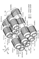
- FIG. 2 is a schematic perspective view illustrating a part of the power transmission device according to at least one embodiment of the present disclosure.
- FIG. 3 is a schematic perspective view illustrating a configuration example of the power transmission device according to the embodiment.
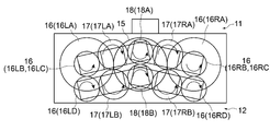
- FIG. 4 is a schematic diagram illustrating a configuration example of a power transmission device according to an embodiment.
- the power transmission device 10 according to at least one embodiment of the present disclosure is configured to transmit the driving force of the motor 14 to one driven shaft 2 (for example, the rolling roll 2A).
- a motor as a rotational force opposite to the one driven shaft 2 with respect to one power transmission path 11 and another driven shaft 2 (for example, a rolling roll 2B) disposed opposite to the one driven shaft.
- a second power transmission path 12 for transmitting 14 driving forces.
- the power transmission device 10 includes a casing 13 that houses the first power transmission path 11 and the second power transmission path 12.
- Each of the first power transmission path 11 and the second power transmission path 12 is provided with only one of them depending on the arrangement of the driven shafts 2 or is in a positional relationship such as up and down or left and right. Or are arranged as follows. At least one of the first power transmission path 11 and the second power transmission path 12 has a first intermediate rotating body 16 that is fixed with respect to the output shaft 15 of the motor 14 and rotated by the driving force of the motor 14. A second intermediate rotating body 17 that is rotated by the first intermediate rotating body 16 and moves along the outer periphery of the first intermediate rotating body 16, and is rotated by the second intermediate rotating body 17 and driven to one or another driven shaft. And a drive shaft 18 for transmitting force. For example, in FIGS.
- each of the first power transmission path 11 and the second power transmission path 12 is 1 shows a configuration example including a first intermediate rotator 16, a second intermediate rotator 17, and a drive shaft 18.
- FIGS. 1 and 2 show the first power transmission path 11 and the second power transmission only on the left side.
- route 12 is shown, and FIG.3 and FIG.4 has shown the structure provided with the said 1st power transmission path
- the output shaft 15, the first intermediate rotator 16, the second intermediate rotator 17, and the drive shaft 18 are supported such that their central axes rotate within the casing 13 via bearings 30.
- the rotating shaft 160LA of the first intermediate rotating body 16 and the rotating shaft 170LA, the rotating shaft 160LB and the rotating shaft 170LB, the rotating shafts 160RA and 170RA, and the rotating shafts 160RB and 170RB of the second intermediate rotating body 17 are respectively bearings. These are connected by a link 20 described later via 30.
- the drive shaft 18 is supported by a frame 19A, which will be described later, via a rotary shaft 180A (180B) and a bearing 30, and the frame 19A is driven by a second drive unit 22 which will be described later, thereby supporting the support 19B. Guided up and down (described later).
- the output shaft 15, the first intermediate rotator 16, the second intermediate rotator 17, and the drive shaft 18 of the motor 14 are connected to the respective rotating shafts 150, Gears that rotate integrally with the rotary shafts are provided on the outer periphery of 160LA, 160LB, 160RA, 160RB, 170LA, 170LB, 180A, and 180B, and are configured to transmit power by meshing with each other via the gears. May be.
- the output shaft 15 of the motor 14, the first intermediate rotating body 16 (a torque receiving unit 16A described later in more detail), the first intermediate rotating body 16 (the second torque transmitting unit 16C described later in more detail) and the first The first intermediate rotator 16 (first intermediate rotator 16D described later in detail), the first intermediate rotator 16 (first torque transmission unit 16B described later in detail), the second intermediate rotator 17, and the second The intermediate rotator 17 and the drive shaft 18 can be configured to transmit rotational torque by being meshed with each other via gears provided on the outer periphery of each.
- the rotation shaft 160LA disposed next to the output shaft 15 (on the left side) is longer than the other rotation shafts in the axial direction, and in order from the side closer to the output shaft 15, the first intermediate rotation body 16 is provided.
- a torque receiving unit 16LA, a first torque transmitting unit 16LB, and a second torque transmitting unit 16LC are provided.
- the rotation shaft 160RA arranged next to the output shaft 15 (on the right side) is longer than the other rotation shafts in the axial direction, and the first intermediate rotation body in order from the one closer to the output shaft 15 respectively.
- a torque receiving unit 16RA, a first torque transmitting unit 16RB, and a second torque transmitting unit 16RC are provided.
- the second intermediate rotator 17 is arranged such that the locus of movement of the axis of the second intermediate rotator 17 is a circular arc centered on the axis of the first intermediate rotator 16. Therefore, a smooth meshing state can be ensured at all times, and the driving force of the motor 14 can be reliably transmitted to the driven shaft 2.
- the second intermediate rotator 17 moves in an arc along the circumferential direction of the first intermediate rotator 16” means that “the second intermediate rotator 17 "Moving to form a circular arc centered on the axis”.
- the first intermediate rotating body 16 is supported so as to rotate so that the rotation center axis thereof maintains a certain distance from the rotation center axis of the output shaft 15.
- the first intermediate rotator 16 is arranged in parallel with the output shaft 15, and the relative positional relationship of the rotation center axes with respect to the output shaft 15 is fixed. You can also.
- the first intermediate rotating body 16 is formed to be longer than the output shaft 15 in the axial direction.
- the outer periphery on one end side close to the output shaft 15 is arranged on the left side in FIG. 4, for example, a torque receiving portion 16A to which torque is transmitted from the output shaft 15.
- the torque receiving unit 16A is a torque receiving unit 16LA
- the torque receiving unit 16A arranged on the right side is a torque receiving unit 16RA.
- the outer periphery in the middle in the longitudinal direction of the first intermediate rotator 16 is a first torque transmission unit 16B (the left side is the first torque transmission unit 16LB) that transmits torque to the second intermediate rotator 17 of the first power transmission path 11.
- the right side is configured as the first torque transmission unit 16RB). Further, the outer periphery of the first intermediate rotator 16 on the other end side that is far from the output shaft 15 is a second torque transmission unit 16 ⁇ / b> C that transmits torque to the second intermediate rotator 17 of the second power transmission path 12. (The left side is the second torque transmission unit 16LC, and the right side is the second torque transmission unit 16RC).
- the first power transmission path 11 and the second power transmission path 12 are the same as the first intermediate rotor 16 in each power transmission path 11, 12.
- the first intermediate rotating body 16 may be shared. If it does in this way, size reduction of the power transmission device 10 can be achieved.
- the torque receivers 16LA and 16RA and the first torque transmitters 16LB and 16RB constitute the first power transmission path 11, and the torque receivers 16LA and 16RA,
- the two torque transmission units 16LC and 16RC and 16LD and 16RD constitute the second power transmission path 12. That is, the first torque transmission units 16LB and 16RB contribute only to the first power transmission path 11 and do not contribute to the second power transmission path 12.
- any one of the first power transmission path 11 and the second power transmission path 12 may include an odd number of first intermediate rotating bodies 16 as compared with the other. 2 to 4, for example, on the second power transmission path 12 side, one more intermediate rotating body 16D (the first intermediate rotating body 16LD on the left side and the first intermediate rotating body 16LD on the right side) than the first power transmission path 11. 1 is a configuration in which one intermediate rotating body 16RD is provided. In this way, the rotational force in the opposite direction can be transmitted to one driven shaft and the other driven shaft, respectively, so that the transported object sandwiched between these one and other driven shafts ( For example, the metal plate 9) can be transported in the same direction.
- the second intermediate rotator 17 (the second intermediate rotator 17L on the left side and the second intermediate rotator 17R on the right side) maintains its rotation center axis at a constant distance from the rotation center axis of the first intermediate rotator 16. It is supported so that it may rotate.
- the second intermediate rotator 17 maintains the axial distance and parallel positional relationship with the first intermediate rotator 16, and does not slip with the outer periphery of the first intermediate rotator 16 (for example, due to gear meshing or friction). )
- a movable gear for example.
- the rotation axis of the drive shaft 18 is arranged in parallel with the rotation axis of the driven shaft 2 (see FIG. 1).
- the rotation center axis of the drive shaft 18 and the rotation center axis of the driven shaft 2 may be arranged coaxially, for example.
- the drive shaft 18 is configured to be connected to the driven shaft 2 so that the driven shaft 2 can move following the movement of the driven shaft 2 in a direction perpendicular to the axial direction. In some embodiments, for example, as shown in FIGS. 1 to 4, when the power transmission device 10 includes both the first power transmission path 11 and the second power transmission path 12, the distance between the axes of the driven shaft 2 is reduced.
- the drive shafts 18 of the respective power transmission paths are configured such that the distance between the axes is changed while maintaining a parallel positional relationship with each other.
- the drive gear 18A moves upward.
- the drive gear 18A moves downward.
- the drive shaft 18 can move in a direction perpendicular to the axial direction of the drive shaft 18 according to the movement of the second intermediate rotator 17 around the first intermediate rotator 16. It is configured.
- the first power transmission path 11 (upper side) and the second power transmission path 12 (lower side) may be provided on either the left or right side (for example, only the left side in FIG. 2).
- the first power transmission path 11 and the second power transmission path 12 may be provided on both the left and right as viewed from the axial direction.
- the second intermediate rotating body 17 moves (for example, in an arc shape) along the outer periphery of the first intermediate rotating body 16 whose axial center position is fixed with respect to the output shaft 15 of the motor.
- the drive shaft 18 and a driven shaft connected to the drive shaft 18 can be suppressed, high efficiency can be achieved by following the distance between the axes of the driven shafts while suppressing the increase in the length of the shaft coupling 5 and the contact area.
- Torque can be transmitted to
- the area of the meshing surface or friction surface between the drive shaft 18 and the driven shaft that contributes to power transmission can be increased, for example, the diameter of the shaft coupling 5 when transmitting the same torque is reduced. Can do.
- the load capacity can be increased.
- At least one of the first power transmission path 11 or the second power transmission path 12 is connected to the output shaft 15 of the motor 14.
- the second power transmission path 12 (for example, the lower side) includes a pair of left and right first intermediate rotating bodies 16 (16 ⁇ / b> L and 16 ⁇ / b> R) as viewed from the axial direction of the output shaft 15, and a pair of left and right pairs.
- the structure including the second intermediate rotator 17 (17L, 17R) is shown, only the first power transmission path 11 has two pairs of left and right first intermediate rotators 16 (16L, 16R) and a pair of left and right first rotators. 2 intermediate rotating bodies 17 (17L, 17R) may be included.
- the driving force of the motor 14 is transmitted by a pair, that is, a plurality of rotating bodies (the first intermediate rotating bodies 16L and 16R or the second intermediate rotating bodies 17L and 17R).
- the diameter of the rotating body can be reduced as compared with the case of transmitting by the body. Therefore, the size of the power transmission device 10 can be reduced.
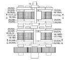
- FIG. 5A is a schematic diagram (plan view) illustrating a configuration example of a power transmission device according to an embodiment.
- FIG. 5B is a schematic diagram (side view) showing a configuration example of a power transmission device according to an embodiment.
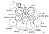
- FIG. 6A is a view showing a cross section AA of FIG. 5A, and is a schematic view showing a (first) power transmission path arranged on the upper side.
- 6B is a diagram showing a BB cross section of FIG. 5A, and is a schematic diagram showing a (second) power transmission path arranged on the lower side.
- FIG. 7 is a schematic side view showing a configuration example of the power transmission device according to the embodiment.
- FIG. 8A is a schematic view showing a CC cross section in FIG.
- FIG. 8B is a schematic diagram showing a DD cross section in FIG. 7 and shows a driving force moving mechanism in the (second) power transmission path arranged on the lower side.
- the first intermediate rotator 16 and the second intermediate rotator 17 may be arranged symmetrically with the drive shaft 18 in between. . That is, the first intermediate rotator 16 may be disposed at the same distance from the drive shaft 18 with the drive shaft 18 interposed therebetween, and the second intermediate rotator 17 may be disposed with the drive shaft 18 interposed therebetween. 18 may be arranged at the same distance from each other. As described above, the first intermediate rotator 16 and the second intermediate rotator 17 are arranged symmetrically with the drive shaft 18 interposed therebetween, so that power that can be reduced in size while suppressing vibration during power transmission.
- a transmission device 10 can be provided.
- the drive shaft 18 configures the first power transmission path 11.
- a first drive shaft (drive gear) 18A that moves in the first movement direction in accordance with the movement of the second intermediate rotators 17LA and 17LB around the first intermediate rotators 16LB and 16RB of the first power transmission path 11.
- a second drive shaft (drive gear) 18B that moves in the second moving direction that is the direction.
- the first drive shaft 18A and the second drive shaft 18B are moved in the first movement direction and the second movement direction, which are opposite to each other, and thus are coupled to the first drive shaft 18A.
- One driven shaft 2A and the other driven shaft 2B connected to the second driving shaft 18B can be moved so that the respective driven shafts 2A and 2B are separated from each other by changing the distance between them. .
- the first drive shaft 18A is connected to the second intermediate rotating body 17 in the first power transmission path 11.
- (17LA, 17RA) rotates around the axis of the first intermediate rotator 16 (16LB, 16RB) in either the clockwise direction or the counterclockwise direction as viewed in the axial direction, It may be configured to move.
- the second drive shaft 18B is configured so that the second intermediate rotating body 17 (17LB, 17RB) is centered on the axis of the first intermediate rotating body 16 (16LD, 16RD) in the second power transmission path 12. It may be configured to move in the second movement direction when rotated in the other direction, either clockwise or counterclockwise when viewed.
- the first drive shaft moves in the first movement direction when the second intermediate rotating body of the first power transmission path rotates in either one of the clockwise direction and the counterclockwise direction as viewed in the axial direction.
- the second drive shaft moves in the second movement direction when the second intermediate rotating body of the second power transmission path rotates in the other direction, either clockwise or counterclockwise, when viewed in the axial direction. That is, in the same axial direction view, the second intermediate rotator of the first power transmission path and the second intermediate rotator of the second power transmission path are rotated in different directions around the axis of the first intermediate rotator.
- the first drive shaft and the second drive shaft can be moved in different directions.
- the second intermediate rotator of the first power transmission path and the second intermediate rotator of the second power transmission path rotate in the same direction around the axis of the first intermediate rotator.
- the first drive shaft and the second drive shaft may be moved in the same direction.
- the drive shaft 18 (first drive shaft 18 ⁇ / b> A) of the first power transmission path 11 is a second drive in the axial direction.
- the second drive shaft 18B may be disposed so as not to overlap with the second drive shaft 18B in a plan view. That is, the drive shaft 18 of the first power transmission path 11 and the drive shaft 18 of the second power transmission path 12 can be arranged so as not to overlap each other in plan view (see, for example, FIG. 1).
- the drive shaft 18 of the first power transmission path 11 and the drive shaft 18 of the second power transmission path 12 are arranged so as to be displaced from each other in a side view, and follow the inter-axis distance of the driven shaft 2.
- the shaft member that connects one of the drive shafts 18 and the driven shaft 2 and the other drive shaft 18 do not interfere (or overlap). Can be placed.
- the drive shafts 18 of the first power transmission path 11 and the second power transmission path 12 are displaced in the axial direction and do not interfere with each other. Interference of the drive shaft 18 can be avoided. Therefore, it is possible to provide the power transmission device 10 that reliably transmits torque while smoothly following the change in the inter-axis distance of the driven shaft.
- both the first power transmission path 11 and the second power transmission path 12 are connected to the first intermediate rotating body 16, the second intermediate rotating body 17, and the drive.
- a shaft 18 may be included. That is, the first power transmission path 11 and the second power transmission path 12 are each configured to transmit power to the pair of driven shafts 2, and each has a drive shaft 18 that is independently provided.
- the drive shaft 18 may be configured to be movable in a direction perpendicular to the axial direction of the drive shaft 18. As described above, according to the configuration in which the drive shafts 18 of the first power transmission path 11 and the second power transmission path 12 are moved in the direction perpendicular to the axial direction, the distance between the axes of the driven shafts is changed. It is possible to smoothly follow the displacement of any driven shaft. In addition, since the two driven shafts 2 can be driven by one motor 14, the power transmission device 10 can be reduced in size.
- the distance between the second intermediate rotating body 17 and the first intermediate rotating body 16 is restricted at least at a part of the rotation axis so that the distance from the first intermediate rotating body 16 is kept constant. Or may be supported so as to be biased toward the first intermediate rotating body 16.
- the second intermediate rotator 17 is supported so that the distance from the drive shaft 18 is constrained in at least a part of the rotation shaft so that the distance from the drive shaft 18 is kept constant. Alternatively, it may be supported so as to be biased toward the drive shaft 18. Examples of the configuration for constraining the distance include a guide groove for guiding each shaft and a link 20 described later.
- the power transmission device 10 includes a part or all of the first intermediate rotator 16, the second intermediate rotator 17, and the drive shaft 18, as illustrated in FIGS. 4 to 6B. 20 may be connected to each other.
- the power transmission device 10 may include, for example, a link 20 ⁇ / b> A that maintains a constant center-to-axis distance between the first intermediate rotator 16 and the second intermediate rotator 17.
- the links 20A may be provided at both ends of the torque receiving portion 16A, both ends of the first torque transmitting portion 16B, and both ends of the second torque transmitting portion 16C in the axial direction. .
- the link 20 ⁇ / b> A may be configured such that the second intermediate rotator 17 side swings about the axis (rotation center axis) of the first intermediate rotator 16.
- the power transmission device 10 may include a link 20B that maintains a constant distance between the axes of the second intermediate rotating body 17 and the drive shaft 18 as shown in FIG. 5A, for example.
- the link 20B may be provided at both ends of the second intermediate rotating body 17 and the drive shaft 18 in the axial direction, for example, as shown in FIG. 5A.
- the link 20 (20A) is kept constant by the link 20 (20A). Therefore, for example, as shown in FIGS.
- the second intermediate is moved on the arc of the first intermediate rotating body 16 with the movement of the drive shaft 18 following the change in the inter-axis distance of the driven shaft 2. Even if the rotator 17 moves, the power can be reliably transmitted without slipping or idling between the intermediate rotators 16 and 17. Further, the distance between the axial centers of the second intermediate rotating body 17 and the drive shaft 18 is maintained constant by the link 20 (20B). Therefore, even if the drive shaft 18 moves on the arc of the second intermediate rotator 17 with the movement of the drive shaft 18 following the change in the inter-axis distance of the driven shaft 2, slipping or idling occurs between them. Power can be reliably transmitted without being generated.
- the power transmission device 10 uses the second intermediate rotator 17 as an operating point with the axis of the first intermediate rotator 16 as a fulcrum, as exemplified in FIGS. 4, 6A and 6B.
- a first drive unit 21 that is connected to the power point of the link 20 (20A) held by the second drive unit 20 and applies a swinging force that moves the second intermediate rotating body 17 along the outer periphery of the first intermediate rotating body 16.
- the 1st drive part 21 may be constituted by actuators, such as an electromagnetic solenoid, a motor, or a hydraulic cylinder, for example.
- the first drive unit 21 is configured to maintain the relative positional relationship between the driven shaft 2 and the drive shaft 18 connected thereto in accordance with the movement of the driven shaft 2. 17 can be controlled to move on the arc of the first intermediate rotator 16.
- the first drive unit 21 that can swing the second intermediate rotator 17 in the first power transmission path 11 around the first intermediate rotator 16 is arranged as shown in FIG. 6A, for example.
- middle rotary body 17 (17LA) of the left side in the 1st power transmission path 11 is the 1st intermediate
- the link 20A is swung around the first intermediate rotator 16 (16LA), and the second intermediate rotator 17 (17LA) moves.
- the first drive unit 21 that swings the second intermediate rotator 17 (17RA) on the right side in the first power transmission path 11 includes the first intermediate rotator 16 (16RA) and the second intermediate rotator. 17 (17RA) is connected to the lower part of the link 20A (in other words, on the side opposite to the operating point with respect to the fulcrum of the link 20A), and the output shaft of the first drive unit 21 moves in the horizontal direction.
- the link 20A is swung around the first intermediate rotator 16 (16RA), and the second intermediate rotator 17 (17RA) moves.
- the links 20A arranged on the right side and the left side can be formed such that the fulcrum, the force point, and the action point are arranged in a straight line.
- the first drive unit 21 that can swing the second intermediate rotator 17 (17LB, 17RB) around the first intermediate rotator 16 (16LD, 16RD) in the second power transmission path 12 is shown in FIG. 6B, for example.
- the drive unit 21 has an upper point of the link 20A connecting the first intermediate rotating body 16 (16LD, 16RD) and the second intermediate rotating body 17 (17LB, 17RB) (in other words, an operating point with respect to the fulcrum of the link 20A).
- the link 20A When the output shaft of the first drive unit 21 moves in the horizontal direction, the link 20A is swung around the first intermediate rotating body 16 (16LD, 16RD), The second intermediate rotator 17 (17LB, 17RB) moves.
- FIG. 6B when the first drive units 21 are arranged with the output shafts directed in the same direction, the advance / retreat of the output shafts of the first drive units 21 can be controlled in opposite phases.
- omitted when each 1st drive part 21 is arrange
- the links 20A arranged on the right side and the left side can be formed such that the fulcrum, the force point, and the action point are arranged in an L shape.
- the first intermediate rotating body 17 can be actively moved along the arc of the first intermediate rotating body 16 by the first driving unit 21.
- the rolling roll 2 that is the driven shaft It is possible to reduce the load on the drive shaft 18 due to the change of the inter-axis distance.
- the power transmission device 10 may include a second drive unit 22 for moving the drive shaft 18 in a direction perpendicular to the axial direction as shown in FIGS. 4, 7, 8 ⁇ / b> A, and 8 ⁇ / b> B, for example.
- the 2nd drive part 22 may be comprised by actuators, such as an electromagnetic solenoid, a motor, or a hydraulic cylinder, for example.
- the second drive unit 22 can be controlled in accordance with the movement of the driven shaft 2 so that the relative positional relationship between the driven shaft 2 and the drive shaft 18 connected thereto is maintained.
- the second drive unit 22 that moves the drive shaft 18 in the first power transmission path 11 in a direction perpendicular to the axial direction of the drive shaft 18 is, for example, as shown in FIG. 8A. Be placed.
- the second drive unit 22 is connected to the lower part of the support 19B that guides the frame 19A that holds the bearing 30 of the drive shaft 18 with the output shaft facing upward, and the output of the second drive unit 22 As the shaft moves in the vertical direction, the drive shaft 18 moves in the vertical direction.
- the second drive unit 22 that moves the drive shaft 18 in the second power transmission path 12 in a direction perpendicular to the axial direction of the drive shaft 18 (for example, the vertical direction) is arranged as shown in FIG. 8B, for example.
- the second drive unit 22 is connected to the upper part of the support 19 ⁇ / b> B that guides the frame 19 ⁇ / b> A that holds the bearing 30 of the drive shaft 18, with the output shaft directed downward, and the output of the second drive unit 22.
- the drive shaft 18 moves in the vertical direction.
- the drive shaft 18 is moved in the direction perpendicular to the axial direction by the second drive unit 22, for example, the change of the inter-axis distance of the driven shaft and the first drive shaft 18 by the second drive unit 22.
- the load on the drive shaft 18 due to the change in the inter-axis distance of the driven shaft can be reduced.
- the rolling mill 1 is provided with the 3rd drive part 23 which provides the motive power which changes the axial distance of a pair of rolling roll 2.
- the 3rd drive part 23 may be comprised by actuators, such as an electromagnetic solenoid, a motor, or a hydraulic cylinder, for example.
- actuators such as an electromagnetic solenoid, a motor, or a hydraulic cylinder, for example.
- at least the 2nd drive part 22 and the 3rd drive part 23 may interlock
- the power transmission device 10 may further include the first drive unit 21 described above, and the first drive unit 21, the second drive unit 22, and the third drive unit 23 are configured to smoothly interlock with each other. It may be.
- the second drive unit 22 that moves at least the drive shaft 18 in the direction perpendicular to the axial direction and the third drive unit 23 that applies power to change the inter-axis distance between the pair of rolling rolls 2 are interlocked. With this configuration, it is possible to maintain the same distance between the axes while suppressing the load on the pair of rolling rolls 2 and the pair of drive shafts 18 due to the change in the distance between the axes. You can plan.
- FIG. 9 is a schematic perspective view illustrating a configuration example of a power transmission device according to another embodiment.
- the output shaft 15, the first intermediate rotator 16, the second intermediate rotator 17, or the drive shaft 18 of the motor 14 may be configured to include a roller, for example as illustrated in a non-limiting manner in FIG. 9. That is, the output shaft 15, the first intermediate rotator 16, the second intermediate rotator 17, and the drive shaft 18 may be configured to transmit rotational torque by the frictional force of each peripheral surface.
- the output shaft 15, the first intermediate rotating body 16, the second intermediate rotating body 17 or the drive shaft 18 of the motor 14 includes the rollers, it is possible to reduce vibration and operating noise during operation. it can.
- the output shaft 15, the first intermediate rotator 16, the second intermediate rotator 17, and the drive shaft 18 described above can reduce the backlash compared to the configuration including gears, the transmission loss of power can be reduced. Can do. Moreover, since it is not necessary to process the gear teeth, man-hours and costs for manufacturing can be reduced.
- the present invention is not limited to the above-described embodiments, and includes forms obtained by changing the above-described embodiments and forms obtained by combining these forms.
- the driving device that drives the rolling roll 2 of the rolling mill 1 is illustrated as the power transmission device 10, but the power transmission device 10 of the present invention is not limited to this.
- the power transmission device 10 may be a drive device for driving a positive displacement pump.
- the positive displacement pump for example, a vane pump or a geared pump may be employed.
- one of the first power transmission path 11 and the second power transmission path 12 may include the first intermediate rotator 16, the second intermediate rotator 17, and the drive shaft 18.
- first power transmission path 11 disposed on the upper side includes the first intermediate rotator 16, the second intermediate rotator 17, and the drive shaft 18, and the upper drive shaft 18 is configured to move up and down.
- second power transmission path 12 disposed on the lower side may include the first intermediate rotator 16, the second intermediate rotator 17, and the drive shaft 18. In this case, the lower drive shaft Only 18 is configured to move up and down.
- Rolling machine Rolling roll (driven shaft) 5 shaft coupling 5A coupling 9 metal plate 10 power transmission device (rolling roll drive mechanism) 11 First power transmission path 12 Second power transmission path 13 Casing 14 Motor 15 Motor output shaft (input shaft) 16 Intermediate gear (first intermediate rotating body) 17 Auxiliary gear (second intermediate rotating body) 18 Drive gear (output shaft / drive shaft) 20 Link 21 1st drive part 22 2nd drive part 23 3rd drive part g Center distance
Landscapes
- Engineering & Computer Science (AREA)
- General Engineering & Computer Science (AREA)
- Mechanical Engineering (AREA)
- Transmission Devices (AREA)
- Gear Transmission (AREA)
Abstract
Dispositif de transmission de puissance comprenant : un premier chemin de transmission de puissance pour transmettre une force d'entraînement d'un moteur à un premier arbre entraîné ; et un second chemin de transmission de puissance pour transmettre la force d'entraînement du moteur à un autre arbre entraîné disposé de manière à être opposé audit premier arbre entraîné. Le premier chemin de transmission de puissance et/ou le second chemin de transmission de puissance comprennent : un premier corps rotatif intermédiaire dont la position d'axe est fixe par rapport à un arbre de sortie du moteur et qui est entraîné en rotation par la force d'entraînement du moteur ; un second corps rotatif intermédiaire qui est entraîné en rotation par le premier corps rotatif intermédiaire et qui est déplacé selon un arc le long d'une circonférence extérieure du premier corps rotatif intermédiaire ; et un arbre d'entraînement qui est entraîné en rotation par le second corps rotatif intermédiaire et qui transmet la force d'entraînement audit ou auxdits autres arbres entraînés. L'arbre d'entraînement est conçu de façon à se déplacer dans une direction perpendiculaire à la direction axiale de l'arbre d'entraînement conformément au déplacement du second corps rotatif intermédiaire autour du premier corps rotatif intermédiaire.
Priority Applications (4)
| Application Number | Priority Date | Filing Date | Title |
|---|---|---|---|
| US16/637,055 US11273478B2 (en) | 2018-06-07 | 2019-06-07 | Power transmission device and rolling mill |
| CN201980003828.3A CN111051735B (zh) | 2018-06-07 | 2019-06-07 | 动力传递装置以及压延机 |
| EP19814246.5A EP3650732B1 (fr) | 2018-06-07 | 2019-06-07 | Dispositif de transmission de puissance et laminoir |
| JP2020523198A JP6839330B2 (ja) | 2018-06-07 | 2019-06-07 | 動力伝達装置及び圧延機 |
Applications Claiming Priority (2)
| Application Number | Priority Date | Filing Date | Title |
|---|---|---|---|
| JP2018109132 | 2018-06-07 | ||
| JP2018-109132 | 2018-06-07 |
Publications (1)
| Publication Number | Publication Date |
|---|---|
| WO2019235607A1 true WO2019235607A1 (fr) | 2019-12-12 |
Family
ID=68769833
Family Applications (1)
| Application Number | Title | Priority Date | Filing Date |
|---|---|---|---|
| PCT/JP2019/022687 Ceased WO2019235607A1 (fr) | 2018-06-07 | 2019-06-07 | Dispositif de transmission de puissance et laminoir |
Country Status (5)
| Country | Link |
|---|---|
| US (1) | US11273478B2 (fr) |
| EP (1) | EP3650732B1 (fr) |
| JP (1) | JP6839330B2 (fr) |
| CN (1) | CN111051735B (fr) |
| WO (1) | WO2019235607A1 (fr) |
Families Citing this family (2)
| Publication number | Priority date | Publication date | Assignee | Title |
|---|---|---|---|---|
| CN115217923A (zh) * | 2022-06-10 | 2022-10-21 | 三联传动机械有限公司 | 一种多齿轮传动的分配箱 |
| CN115388147B (zh) * | 2022-07-15 | 2023-09-08 | 中群(浙江)传动机械有限公司 | 一种悬臂辊型专用减速机组 |
Citations (5)
| Publication number | Priority date | Publication date | Assignee | Title |
|---|---|---|---|---|
| JPS3211596Y1 (fr) * | 1956-05-28 | 1957-09-21 | ||
| JPS5179516U (fr) * | 1974-12-20 | 1976-06-23 | ||
| JPS5184301U (fr) * | 1974-12-26 | 1976-07-06 | ||
| JPS56143845A (en) * | 1980-04-09 | 1981-11-09 | Ishikawajima Harima Heavy Ind Co Ltd | Driving gear |
| JP5984910B2 (ja) | 2012-02-22 | 2016-09-06 | 三菱重工コンプレッサ株式会社 | ターニング装置、および、回転機械 |
Family Cites Families (16)
| Publication number | Priority date | Publication date | Assignee | Title |
|---|---|---|---|---|
| GB803809A (en) * | 1956-03-12 | 1958-11-05 | Jidet | Improvements in or relating to a driving device for a rolling mill and similar machines |
| US3293898A (en) * | 1964-03-16 | 1966-12-27 | Falk Corp | Auxiliary drive system for steel rolling mills |
| DE1602018B2 (de) * | 1967-06-22 | 1971-07-08 | Kammwalzengeruest | |
| CH480884A (it) * | 1967-09-22 | 1969-11-15 | Ceretti Ind Spa | Gruppo di comando per le gabbie di laminatoi |
| BE757190A (fr) * | 1969-10-21 | 1971-03-16 | Karlstad Mekaniska Ab | Mecanisme de commande pour cylindre |
| JPS5179516A (fr) | 1975-01-06 | 1976-07-10 | Hitachi Ltd | |
| JPS5184301A (ja) | 1975-08-05 | 1976-07-23 | Rin Eisha Kk | Hangurumojomonotaipuhoshiki |
| DE2753293C3 (de) * | 1977-11-30 | 1980-06-04 | Blohm + Voss Ag, 2000 Hamburg | Antrieb eines Schraubennahtrohrwerkes |
| DE2753292A1 (de) * | 1977-11-30 | 1979-05-31 | Paper Converting Machine Co | Palettiervorrichtung |
| DE3001343C2 (de) * | 1980-01-16 | 1982-05-27 | Kocks Technik GmbH & Co, 4000 Düsseldorf | Getriebe zum Antrieb der Walzen einer Walzstraße |
| DE3119407A1 (de) * | 1981-05-15 | 1982-12-02 | Bwg Bergwerk- Und Walzwerk-Maschinenbau Gmbh, 4100 Duisburg | Anstellvorrichtung zum einstellen des walzenabstandes in walzgeruesten |
| JP2859876B2 (ja) * | 1988-01-11 | 1999-02-24 | 株式会社日立製作所 | 圧延設備用駆動機 |
| NL9201082A (nl) * | 1992-06-19 | 1994-01-17 | Crown Gear Bv | Overbrengingssamenstel voor het aandrijven van twee in hoofdzaak evenwijdig gerichte assen. |
| JP3791663B2 (ja) | 2000-01-17 | 2006-06-28 | 富士電機ホールディングス株式会社 | 全方向移動車両とその制御方法 |
| GB0015115D0 (en) * | 2000-06-20 | 2000-08-09 | Worrall Trevor J | Geared transmissions |
| JP6562794B2 (ja) * | 2015-09-16 | 2019-08-21 | 三菱電機株式会社 | アクチュエータ |
-
2019
- 2019-06-07 WO PCT/JP2019/022687 patent/WO2019235607A1/fr not_active Ceased
- 2019-06-07 CN CN201980003828.3A patent/CN111051735B/zh active Active
- 2019-06-07 EP EP19814246.5A patent/EP3650732B1/fr active Active
- 2019-06-07 JP JP2020523198A patent/JP6839330B2/ja active Active
- 2019-06-07 US US16/637,055 patent/US11273478B2/en active Active
Patent Citations (5)
| Publication number | Priority date | Publication date | Assignee | Title |
|---|---|---|---|---|
| JPS3211596Y1 (fr) * | 1956-05-28 | 1957-09-21 | ||
| JPS5179516U (fr) * | 1974-12-20 | 1976-06-23 | ||
| JPS5184301U (fr) * | 1974-12-26 | 1976-07-06 | ||
| JPS56143845A (en) * | 1980-04-09 | 1981-11-09 | Ishikawajima Harima Heavy Ind Co Ltd | Driving gear |
| JP5984910B2 (ja) | 2012-02-22 | 2016-09-06 | 三菱重工コンプレッサ株式会社 | ターニング装置、および、回転機械 |
Non-Patent Citations (1)
| Title |
|---|
| See also references of EP3650732A4 |
Also Published As
| Publication number | Publication date |
|---|---|
| EP3650732A1 (fr) | 2020-05-13 |
| EP3650732B1 (fr) | 2023-04-19 |
| US11273478B2 (en) | 2022-03-15 |
| EP3650732A4 (fr) | 2020-11-04 |
| CN111051735B (zh) | 2023-01-17 |
| CN111051735A (zh) | 2020-04-21 |
| US20200238352A1 (en) | 2020-07-30 |
| JPWO2019235607A1 (ja) | 2020-12-17 |
| JP6839330B2 (ja) | 2021-03-03 |
Similar Documents
| Publication | Publication Date | Title |
|---|---|---|
| US10865853B2 (en) | Multi-crankshaft cycloidal pin wheel reducer | |
| US8117945B2 (en) | Hollow speed reducer | |
| CN104285077B (zh) | 行星摩擦轮变速器以及变速和差速传动机构 | |
| US12018725B2 (en) | Shaft couplings | |
| WO2019235607A1 (fr) | Dispositif de transmission de puissance et laminoir | |
| WO2017212754A1 (fr) | Mécanisme d'entraînement en rotation omnidirectionnel et corps mobile | |
| JP5644455B2 (ja) | ローラ式摩擦伝動ユニット | |
| US1762199A (en) | Variable-speed transmission | |
| CN108612817B (zh) | 无级变速器 | |
| JP5812857B2 (ja) | 多段圧延機の駆動機構 | |
| JP2020029914A (ja) | ハイポサイクロイド減速機 | |
| JPH0364638B2 (fr) | ||
| EP3325181B1 (fr) | Dispositif vibrateur | |
| JP2015132359A (ja) | 減速機 | |
| JP2007057040A (ja) | 無段変速装置 | |
| CN111188835B (zh) | 运行在曲线导轨上的滑块装置 | |
| EP3864320B1 (fr) | Transmission à variation continue | |
| JP5102206B2 (ja) | 金属製品を加工するために使用される機械のためのローラ作動装置 | |
| JP2014062590A (ja) | 減速機 | |
| US870997A (en) | Change-speed apparatus. | |
| JP7229072B2 (ja) | 減速装置 | |
| JP5736426B2 (ja) | マルチディスク変速機 | |
| AU2021100447A4 (en) | The innovative transmission device relates to a coaxial transmission in which an input shaft and an output shaft are coaxial. The aim of the invention is to provide a coaxial transmission which is simple in structure, small in size, low in cost and will have a long operational life without damage. | |
| JP3220154U6 (ja) | マルチクランクシャフトサイクロイドピン歯車減速機 | |
| US2832287A (en) | Printer slotter roller adjustment |
Legal Events
| Date | Code | Title | Description |
|---|---|---|---|
| 121 | Ep: the epo has been informed by wipo that ep was designated in this application |
Ref document number: 19814246 Country of ref document: EP Kind code of ref document: A1 |
|
| ENP | Entry into the national phase |
Ref document number: 2020523198 Country of ref document: JP Kind code of ref document: A |
|
| ENP | Entry into the national phase |
Ref document number: 2019814246 Country of ref document: EP Effective date: 20200206 |
|
| NENP | Non-entry into the national phase |
Ref country code: DE |