WO2019239573A1 - Machine de travail - Google Patents
Machine de travail Download PDFInfo
- Publication number
- WO2019239573A1 WO2019239573A1 PCT/JP2018/022876 JP2018022876W WO2019239573A1 WO 2019239573 A1 WO2019239573 A1 WO 2019239573A1 JP 2018022876 W JP2018022876 W JP 2018022876W WO 2019239573 A1 WO2019239573 A1 WO 2019239573A1
- Authority
- WO
- WIPO (PCT)
- Prior art keywords
- imaging
- component
- lead
- electrical component
- held
- Prior art date
- Legal status (The legal status is an assumption and is not a legal conclusion. Google has not performed a legal analysis and makes no representation as to the accuracy of the status listed.)
- Ceased
Links
Images


Classifications
-
- H—ELECTRICITY
- H05—ELECTRIC TECHNIQUES NOT OTHERWISE PROVIDED FOR
- H05K—PRINTED CIRCUITS; CASINGS OR CONSTRUCTIONAL DETAILS OF ELECTRIC APPARATUS; MANUFACTURE OF ASSEMBLAGES OF ELECTRICAL COMPONENTS
- H05K13/00—Apparatus or processes specially adapted for manufacturing or adjusting assemblages of electric components
- H05K13/08—Monitoring manufacture of assemblages
Definitions
- the present invention relates to a working machine including a working head having a holding tool and an imaging device that images an electrical component held by the holding tool.
- the following patent document discloses a working machine including a working head having a holding tool and an imaging device that images an electrical component held by the holding tool.
- the present specification includes a working head having a holder and an imaging device that images the electrical component held by the holder, and the electrical component captured by the imaging device is provided.
- a working machine that performs both calculation of information regarding the position of the electrical component and determination of whether or not foreign matter has adhered to the electrical component based on imaging data.
- FIG. 1 shows a component mounter 10.
- the component mounter 10 is a device for performing a component mounting operation on the circuit substrate 12.
- the component mounting machine 10 includes an apparatus main body 20, a base material conveyance holding device 22, a component mounting device 24, a mark camera (see FIG. 2) 26, a side camera (see FIG. 3) 28, a component supply device 30, and a bulk component supply device 32.
- a control device (see FIG. 4) 34 is provided.
- the circuit substrate 12 includes a circuit board, a three-dimensional structure substrate, and the like, and the circuit board includes a printed wiring board and a printed circuit board.
- the apparatus main body 20 includes a frame portion 40 and a beam portion 42 that is overlaid on the frame portion 40.
- the substrate conveyance holding device 22 is disposed in the center of the frame portion 40 in the front-rear direction, and includes a conveyance device 50 and a clamp device 52.
- the conveyance device 50 is a device that conveys the circuit substrate 12
- the clamp device 52 is a device that holds the circuit substrate 12.
- the base material transport and holding device 22 transports the circuit base material 12 and holds the circuit base material 12 fixedly at a predetermined position.
- the conveyance direction of the circuit substrate 12 is referred to as an X direction
- a horizontal direction perpendicular to the direction is referred to as a Y direction
- a vertical direction is referred to as a Z direction. That is, the width direction of the component mounting machine 10 is the X direction, and the front-rear direction is the Y direction.
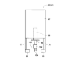
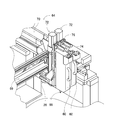
- the component mounting device 24 is disposed in the beam portion 42 and includes two work heads 60 and 62 and a work head moving device 64. As shown in FIG. 2, the work heads 60 and 62 have a rod-like mounting unit 66, and the mounting unit 66 is vertically extended by a head body 67 of the work heads 60 and 62 in a posture extending in a vertical direction. It is slidable in the direction and is held so as to be rotatable about the axis. Note that the lower end portion of the mounting unit 66 extends downward from the lower surface of the head main body 67, and the suction nozzle 68 is mounted on the lower end portion of the mounting unit 66. The component is sucked and held by the suction nozzle 68.
- the work heads 60 and 62 have a lifting device (not shown) that lifts and lowers the mounting unit 66 and a rotation device (not shown) that rotates the mounting unit 66 around the axis. Accordingly, the component held by the suction nozzle 68 can be moved in the vertical direction, and the posture of the component held by the suction nozzle 68 can be changed.
- the rotation device can arbitrarily adjust the rotation angle of the mounting unit 66, and can position the rotation angle of the component held by the suction nozzle 68.
- the work head moving device 64 has an X direction moving device 69, a Y direction moving device 70, and a Z direction moving device 72. Then, the two working heads 60 and 62 are integrally moved to an arbitrary position on the frame unit 40 by the X direction moving device 69 and the Y direction moving device 70.
- the work heads 60 and 62 are detachably mounted on the sliders 74 and 76 with one touch, and the Z-direction moving device 72 individually moves the sliders 74 and 76 in the vertical direction. That is, the work heads 60 and 62 are individually moved in the vertical direction by the Z-direction moving device 72.
- the mark camera 26 is attached to the slider 74 so as to face downward, and is moved together with the work head 60 in the X direction, the Y direction, and the Z direction. As a result, the mark camera 26 images an arbitrary position on the frame unit 40.
- the side camera 28 is attached to the work heads 60 and 62 as shown in FIG. Specifically, an arm 77 is fixed to the edge of the lower surface of the work heads 60 and 62 so as to extend downward. Then, one side camera 28 is fixed to the lower end of the arm 77 in a state where it faces the component suction position of the suction nozzle 68. That is, the side camera 28 moves in the X direction and the Y direction together with the suction nozzle 68 by the work head moving device 64.
- the lifting range of the mounting unit 66 by the lifting device is set so that the component held by the suction nozzle 68 falls within the imaging range by the side camera 28.
- the side camera 28 images the component held by the suction nozzle 68.
- An arm 78 having the same shape as the arm 77 is fixed to the edge of the lower surface of the work heads 60 and 62 at a position symmetrical to the arm 77 around the suction nozzle 68 so as to extend downward.
- the light 80 is being fixed to the lower end part of the arm 78 in the state which faced the component adsorption position of the adsorption nozzle 68.
- the side camera 28 and the light 80 are arranged at two equal positions with the suction nozzle 68 interposed therebetween, and the side camera 28 and the light 80 face each other. For this reason, the imaging range by the side camera 28 and the irradiation range by the light 80 overlap.
- the component supply apparatus 30 is arrange
- the component supply device 30 includes a tray-type component supply device 86 and a feeder-type component supply device (see FIG. 4) 88.
- the tray-type component supply device 86 is a device that supplies components placed on the tray.
- the feeder-type component supply device 88 is a device that supplies components using a radial feeder (not shown). Since the radial feeder is a known device, in brief, it is a device that cuts the radial lead component (see FIG. 2) 100 from the taped component (not shown) and supplies the radial lead component 100.
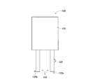
- the radial lead component 100 includes a main body portion 102 and two leads 104 extending in the same direction from the bottom surface of the main body portion 102.
- the radial lead component 100 is a carrier in the lead 104. Taped on a tape (not shown). Then, the radial feeder cuts the lead 104 taped on the carrier tape and supplies the radial lead component 100.
- the bulk component supply device 32 is disposed at the other end portion in the front-rear direction of the frame portion 40.
- the separated component supply device 32 is a device for aligning a plurality of components scattered in a separated state and supplying the components in an aligned state. That is, it is an apparatus that aligns a plurality of components in an arbitrary posture into a predetermined posture and supplies the components in a predetermined posture.
- an electrical component, a component part of a solar cell, a component part of a power module, etc. are mentioned as a component supplied by the component supply apparatus 30 and the bulk component supply apparatus 32.
- the electrical parts include parts having leads such as radial lead parts 100, parts not having leads such as square chips, atypical electrical parts, and the like.
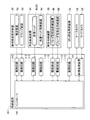
- the control device 34 includes a controller 110, a plurality of drive circuits 112, and an image processing device 114.
- the plurality of drive circuits 112 are connected to the transport device 50, the clamp device 52, the work heads 60 and 62, the work head moving device 64, the tray-type component supply device 86, the feeder-type component supply device 88, and the bulk component supply device 32.
- the controller 110 includes a CPU, a ROM, a RAM, and the like, mainly a computer, and is connected to a plurality of drive circuits 112. Thereby, the operations of the substrate conveyance holding device 22 and the component mounting device 24 are controlled by the controller 110. Furthermore, the controller 110 is also connected to the image processing device 114.
- the image processing device 114 processes image data obtained by the mark camera 26 and the side camera 28, and the controller 110 acquires various types of information from the image data.
- the component mounting operation is performed on the circuit substrate 12 held by the substrate conveyance holding device 22 with the above-described configuration. Specifically, the circuit substrate 12 is transported to the work position, and is fixedly held by the clamp device 52 at that position. Next, the mark camera 26 moves above the circuit substrate 12 and images the circuit substrate 12. At this time, imaging data obtained by imaging by the mark camera 26 is transmitted to the controller 110, and the imaging data is analyzed by the controller 110. Thereby, the information regarding the holding position of the circuit base material 12 and the position of the lead insertion hole of the lead component provided in the circuit base material 12 is calculated.
- the component supply device 30 or the bulk component supply device 32 supplies the component at a predetermined supply position.
- a case where the component is supplied by the feeder-type component supply device 88 of the component supply device 30 will be described.
- the radial feeder is supplied with the main body 102 facing upward and the two leads 104 facing downward. Then, the work heads 60 and 62 move above the radial feeder component supply position, and the suction nozzle 68 holds the radial lead component 100 on the upper surface of the main body 102 as shown in FIG.
- the radial lead component 100 is imaged by one side camera 28.
- the operation of the lifting device is controlled so that the lead 104 of the radial lead component 100 held by the suction nozzle 68 falls within the imaging range of the side camera 28 and the irradiation range of the light 80.
- the mounting unit 66 moves up and down.
- the light 80 is turned on toward the lead 104 of the radial lead component 100, and the lead 104 is imaged by the side camera 28.
- the mounting unit 66 rotates by the operation of the rotation device during imaging.
- the side camera 28 images the lead 104 a plurality of times as the mounting unit 66 rotates, that is, as the suction nozzle 68 rotates.
- the rotation device temporarily stops to position the radial lead component held by the suction nozzle at a predetermined angle. Then, when stopped, the side camera 28 images the lead 104 that has been positioned and stopped.
- the side camera 28 images the lead 104 a plurality of times in a state where the posture of the lead 104 to be imaged is changed, that is, in a state where the imaging condition is changed.
- the side camera 28 captures the lead 104 a plurality of times and acquires a plurality of imaging data in a state where the imaging location and imaging angle of the lead 104 are changed.
- the work heads 60 and 62 and the suction nozzle 68 are stopped during imaging by the side camera 28. This prevents blurring during imaging.
- a plurality of imaging data obtained by imaging a plurality of times by the side camera 28 is transmitted to the controller 110, and the plurality of imaging data is analyzed by the controller 110. Thereby, information related to the tip position of the lead 104 is calculated and acquired by the controller 110.
- the through hole formed in the circuit board 12 and the tip of the lead 104 of the radial lead component 100 are in the vertical direction.
- the operation of the work head moving device 64 is controlled so that the radial lead component 100 held by the suction nozzle 68 is positioned.
- the mounting unit 66 is lowered by the operation of the lifting device, the lead 104 of the radial lead component 100 is inserted into the through hole of the circuit base 12 and the radial lead component 100 is mounted on the circuit base 12. It becomes.
- the components supplied by the component supply device 30 and the like are held by the suction nozzle 68 and mounted on the circuit substrate 12.
- the circuit substrate 12 may become a defective product.
- the radial lead component 100 supplied by the radial feeder since the radial lead component 100 is supplied after the lead 104 is cut by the radial feeder, as shown in FIG. May adhere.
- chips generated by the cutting and carrier tape ridges 122 may also adhere to the leads 104.
- the foreign matter means an irregular shape different from a normal one, and the foreign matter includes an integral part of the lead 104.
- the scrap 104, dust, dust, and the like that are separate from the lead 104 are naturally foreign matter, but the burr 120 of the lead 104 that is integral with the lead 104 is also a foreign matter.
- the lead 104 when the lead 104 is imaged by the side camera 28 in order to calculate the tip position of the lead 104, not only the tip position of the lead 104 is calculated but also foreign matter adheres to the lead 104. Existence is confirmed. That is, in the component mounting operation, as described above, after the radial lead component 100 is held by the suction nozzle 68 from the radial feeder, the lead 104 of the radial lead component 100 held by the suction nozzle 68 is held in the work head 60. Is imaged by the side camera 28.
- the mounting unit 66 rotates to change the posture of the lead 104 of the radial lead component 100 held by the suction nozzle 68, and the lead 104 is imaged a plurality of times by the side camera 28. Then, a plurality of imaging data obtained by imaging a plurality of times by the side camera 28 is transmitted to the controller 110, and the plurality of imaging data is analyzed by the controller 110. At this time, information on the position of the lead 104 is calculated from the plurality of imaging data by the controller 110, and whether or not a foreign substance has adhered to the lead 104 is determined from the plurality of imaging data. As a method for determining the presence or absence of a foreign object, it is determined that there is a foreign object when the size of the shadow of the lead 104 generated by the light 80 projection is larger than a threshold value with respect to the outer dimension of the lead 104.
- the foreign matter is determined based on the shadow of the lead 104 generated by the light projecting from the side of the lead 104, and as shown in FIG.
- flash 120a formed in this way can be confirmed suitably.
- the burr 120b formed so as to extend to the side of the lead 104 and the flange 122 attached to the side surface of the lead 104 by the mounting unit 66 rotating and changing the posture of the lead 104 during imaging. It can confirm suitably.
- the radial lead component 100 held by the suction nozzle 68 is discarded in a disposal box (not shown) without being attached to the circuit base 12. Is done. Thereby, while bringing in the foreign material to the circuit base material 12, generation
- both the calculation of the tip position of the lead 104 and the determination of the presence or absence of foreign matter adhering to the lead 104 are executed based on the image data taken by the side camera 28. That is, two different processes can be executed using image data obtained by one side camera 28. This eliminates the need to install multiple cameras for each process or re-image each process, reducing costs, reducing the data processing time by parallel processing of image data and image data, and space saving. Can be planned.
- the calculation of the part position and the determination of the presence or absence of a foreign object are performed based on the imaging data imaged at the viewpoint from the side of the part.
- the calculation of the part position and the presence / absence of a foreign object are performed based on the imaging data taken from the viewpoint from below the part.
- an imaging device 150 shown in FIG. 6 is employed instead of the side camera 28.
- the imaging device 150 is a camera that can acquire a 3D image, and is a so-called 3D camera.
- the imaging device 150 includes a parts camera 152, a lens 154, and a lighting device 156.
- the parts camera 152 has an image sensor (not shown), and is arranged with the light receiving surface facing upward.
- the lens 154 is fixed to the light receiving surface side of the parts camera 152, that is, the upper surface side of the parts camera 152, and an illumination device 156 is provided on the lens 154 via a box-shaped member 157.
- the illuminating device 156 includes a housing 158 and four lights 160 (only two lights are shown in the drawing) 160.
- the housing 158 is generally bowl-shaped. On the surface of the housing 158, LEDs are arranged as a part lighting device, and the upper and lower surfaces are opened.
- a plurality of LEDs can be turned on at any number of positions according to the imaging conditions of the component. And it arrange
- the predetermined position is an imaging position of a component held by the suction nozzle 68 located within the range of the depth of field of the imaging device 150.
- One imaging device 150 having such a structure is fixedly disposed between the component supply device 30 and the base material conveyance holding device 22 on the upper surface of the frame portion 40 of the component mounter 10. Then, when a component supplied from the component supply device 30 or the like is held by the suction nozzle 68, the component moves to the predetermined position, that is, a position where the light emitted from the four lights 160 converges. In this way, the operation of the work head moving device 64 is controlled.
- a lead-free component for example, a square chip 170 is held by the suction nozzle 68 will be described.
- the movement of the work heads 60 and 62 stops and remains at that position.
- the first light 160 of the four lights 160 is turned on.
- the corner chip 170 is irradiated with light from the direction in which the first light 160 of the four lights 160 is disposed.
- the corner chip 170 is imaged by the parts camera 152.
- the first light 160 is turned off and the second light 160 is turned on.
- the corner chip 170 is irradiated with light from a direction different from that of the first light 160.
- the corner chip 170 is imaged by the parts camera 152.
- the second light 160 is turned off and the third light 160 is turned on.
- the corner chip 170 is irradiated with light from a direction different from that of the first light 160 and the second light 160.
- the corner chip 170 is imaged by the parts camera 152.
- the third light 160 is turned off and the fourth light 160 is turned on.
- the corner chip 170 is irradiated with light from a direction different from that of the first to third lights 160.
- the corner chip 170 is imaged by the parts camera 152. Thereby, the corner chip 170 is imaged every time it is irradiated in a state where light is irradiated from each of four different directions.
- the imaging device 150 images the corner chip 170 a plurality of times with the irradiation position changed, that is, with the imaging condition changed.
- the imaging device 150 is fixedly stopped with respect to the square chip imaging device which is a component held by the holder, and the irradiation angle and irradiation of light to the square chip 170 are irradiated.
- the corner chip 170 is imaged a plurality of times.
- the work heads 60 and 62 do not move during imaging by the parts camera 152, and the square chip 170 held by the suction nozzle 68 remains at the predetermined position. That is, at one imaging position, the corner chip 170 is imaged a plurality of times in a stopped state.
- a plurality of imaging data obtained by imaging a plurality of times by the imaging device 150 is transmitted to the controller 110.
- the controller 110 analyzes a plurality of transmitted imaging data and calculates the holding position of the square chip 170 by the suction nozzle 68. Further, the controller 110 calculates information on the three-dimensional outline of the corner chip 170, that is, the three-dimensional shape of the corner chip 170 (hereinafter referred to as “calculation three-dimensional shape”) based on a plurality of imaging data. Is done. Further, the controller 110 stores an actual three-dimensional shape of the square chip 170 (hereinafter referred to as “real three-dimensional shape”). A catalog value or the like is used for the actual three-dimensional shape.
- the calculated three-dimensional shape and the actual three-dimensional shape are compared, and when the difference is equal to or larger than the threshold value, it is determined that there is a foreign object.
- the imaging device 150 having the 3D imaging function it is possible to appropriately determine the presence or absence of foreign matter.
- a camera that does not have a 3D imaging function it is possible to obtain only imaging data of a component irradiated with light only from a predetermined direction without moving the component held by the holder. It is possible to calculate and acquire a three-dimensional composite image, that is, only a two-dimensional shape of a component. As a result, since a blind spot may occur in the captured image of the part, it is not possible to determine the state of the part more accurately than the three-dimensional shape data.
- the imaging device 150 having a 3D imaging function can obtain a plurality of imaging data of a component irradiated from each of a plurality of directions, so that a blind spot hardly occurs by calculating a three-dimensional shape of the component. .
- the component is irradiated with light from each of a plurality of directions without moving the angle or position of the component held by the holder with respect to the imaging apparatus, one of the irradiation lights from the plurality of directions.
- the imaging device 150 having a 3D imaging function, foreign matter determination based on imaging data can be appropriately performed.
- both the calculation of the holding position of the corner chip 170 and the determination of the presence or absence of foreign matter adhering to the corner chip 170 are executed based on the imaging data by the imaging device 150. That is, two different processes can be executed in parallel on the basis of the imaging data from one imaging device 150. This eliminates the need for a camera for each process, thereby reducing costs, shortening the processing time, saving space, and the like.
- the component mounting machine 10 is an example of a working machine.
- the side camera 28 is an example of an imaging device.
- the work heads 60 and 62 are examples of work heads.
- the suction nozzle 68 is an example of a holder.
- the radial lead component 100 is an example of an electrical component.
- the imaging device 150 is an example of an imaging device.
- the square chip 170 is an example of an electrical component.
- this invention is not limited to the said Example, It is possible to implement in the various aspect which gave various change and improvement based on the knowledge of those skilled in the art. Specifically, for example, in the above-described embodiment, as a change in the imaging condition, a change in the position of light applied to the component held by the suction nozzle 68 and a change in the posture of the component held by the suction nozzle 68 are included. Although being executed, other imaging conditions may be changed. Specifically, for example, the shutter speed (exposure time), contrast, resolution, light irradiation angle, light irradiation intensity, and the like of the imaging apparatus may be changed.
- the calculation of information regarding the position of the component and the presence / absence of foreign matter adhering to the component based on the imaging data of the side camera 28 or the imaging device 150, that is, the imaging data of one camera.
- another process may be executed. For example, a coplanarity check or the like may be executed.
- the present invention can be applied not only to the radial lead component 100 and the square chip component but also to various atypical components such as an axial lead component.
- the work heads 60 and 62 are not limited to a single nozzle, and may have a plurality of component suction nozzles. In this case, since the parts can be held in the respective suction nozzles, the respective parts are imaged, and the captured image data of the plurality of parts are collectively calculated to obtain the position data of each part and The presence or absence of foreign matter may be determined.
- a lighting device for lead parts instead of the four lights 160, an arbitrary number of positions and number of LEDs among a plurality of LEDs arranged inside the housing 158 may be irradiated.
- the holder is not limited to the suction nozzle, and a chuck or the like that is gripped by a plurality of claws or the like may be employed.
- Component mounter (work machine) 28: Side camera (imaging device) 60: Work head 62: Work head 68: Suction nozzle (holding tool) 100: Radial lead component (electric part) 150: Imaging device 170: Square chip (Electrical component)
Landscapes
- Engineering & Computer Science (AREA)
- Operations Research (AREA)
- Manufacturing & Machinery (AREA)
- Microelectronics & Electronic Packaging (AREA)
- Supply And Installment Of Electrical Components (AREA)
Abstract
Selon la présente invention, cette machine de travail est pourvue : d'une tête de travail comprenant un outil de maintien ; et d'un dispositif d'imagerie qui capture une image d'un composant électrique maintenu par l'outil de maintien. Sur la base des données d'imagerie du composant électrique capturées par le dispositif d'imagerie, la machine de travail calcule à la fois des informations concernant la position du composant électrique et détermine la présence ou l'absence de matière étrangère adhérant au composant électrique.
Priority Applications (3)
| Application Number | Priority Date | Filing Date | Title |
|---|---|---|---|
| CN201880094519.7A CN112262621A (zh) | 2018-06-15 | 2018-06-15 | 作业机 |
| PCT/JP2018/022876 WO2019239573A1 (fr) | 2018-06-15 | 2018-06-15 | Machine de travail |
| JP2020525052A JPWO2019239573A1 (ja) | 2018-06-15 | 2018-06-15 | 作業機 |
Applications Claiming Priority (1)
| Application Number | Priority Date | Filing Date | Title |
|---|---|---|---|
| PCT/JP2018/022876 WO2019239573A1 (fr) | 2018-06-15 | 2018-06-15 | Machine de travail |
Publications (1)
| Publication Number | Publication Date |
|---|---|
| WO2019239573A1 true WO2019239573A1 (fr) | 2019-12-19 |
Family
ID=68843087
Family Applications (1)
| Application Number | Title | Priority Date | Filing Date |
|---|---|---|---|
| PCT/JP2018/022876 Ceased WO2019239573A1 (fr) | 2018-06-15 | 2018-06-15 | Machine de travail |
Country Status (3)
| Country | Link |
|---|---|
| JP (1) | JPWO2019239573A1 (fr) |
| CN (1) | CN112262621A (fr) |
| WO (1) | WO2019239573A1 (fr) |
Cited By (1)
| Publication number | Priority date | Publication date | Assignee | Title |
|---|---|---|---|---|
| WO2023053274A1 (fr) * | 2021-09-29 | 2023-04-06 | 株式会社Fuji | Machine de travail pour carte et procédé de fabrication de carte |
Citations (5)
| Publication number | Priority date | Publication date | Assignee | Title |
|---|---|---|---|---|
| JP2007157848A (ja) * | 2005-12-01 | 2007-06-21 | Yamaha Motor Co Ltd | 表面実装機 |
| JP2009253044A (ja) * | 2008-04-07 | 2009-10-29 | Panasonic Corp | 実装データ作成方法、実装データ作成装置、部品実装機、プログラムおよびデータ構造 |
| WO2015011853A1 (fr) * | 2013-07-25 | 2015-01-29 | パナソニックIpマネジメント株式会社 | Appareil de montage de composants électroniques et procédé de montage de composants électroniques |
| JP2017220599A (ja) * | 2016-06-09 | 2017-12-14 | パナソニックIpマネジメント株式会社 | 部品装着装置および部品装着方法 |
| WO2018047252A1 (fr) * | 2016-09-07 | 2018-03-15 | 富士機械製造株式会社 | Dispositif de reconnaissance |
Family Cites Families (5)
| Publication number | Priority date | Publication date | Assignee | Title |
|---|---|---|---|---|
| JP2950650B2 (ja) * | 1991-06-24 | 1999-09-20 | 株式会社東芝 | 電子部品装着装置及び電子部品装着方法 |
| EP1676474A1 (fr) * | 2003-10-23 | 2006-07-05 | Matsushita Electric Industrial Co., Ltd. | Appareil permettant de determiner des modeles d'implantation d'elements de support |
| JP5812783B2 (ja) * | 2011-09-21 | 2015-11-17 | 富士機械製造株式会社 | 電子回路部品装着機 |
| JP6043994B2 (ja) * | 2011-11-02 | 2016-12-14 | Jukiオートメーションシステムズ株式会社 | 実装装置、部品切れ判定方法及びプログラム |
| JP2014038045A (ja) * | 2012-08-17 | 2014-02-27 | Sony Corp | 検査装置、照明、検査方法、プログラム及び基板の製造方法 |
-
2018
- 2018-06-15 WO PCT/JP2018/022876 patent/WO2019239573A1/fr not_active Ceased
- 2018-06-15 CN CN201880094519.7A patent/CN112262621A/zh active Pending
- 2018-06-15 JP JP2020525052A patent/JPWO2019239573A1/ja active Pending
Patent Citations (5)
| Publication number | Priority date | Publication date | Assignee | Title |
|---|---|---|---|---|
| JP2007157848A (ja) * | 2005-12-01 | 2007-06-21 | Yamaha Motor Co Ltd | 表面実装機 |
| JP2009253044A (ja) * | 2008-04-07 | 2009-10-29 | Panasonic Corp | 実装データ作成方法、実装データ作成装置、部品実装機、プログラムおよびデータ構造 |
| WO2015011853A1 (fr) * | 2013-07-25 | 2015-01-29 | パナソニックIpマネジメント株式会社 | Appareil de montage de composants électroniques et procédé de montage de composants électroniques |
| JP2017220599A (ja) * | 2016-06-09 | 2017-12-14 | パナソニックIpマネジメント株式会社 | 部品装着装置および部品装着方法 |
| WO2018047252A1 (fr) * | 2016-09-07 | 2018-03-15 | 富士機械製造株式会社 | Dispositif de reconnaissance |
Cited By (3)
| Publication number | Priority date | Publication date | Assignee | Title |
|---|---|---|---|---|
| WO2023053274A1 (fr) * | 2021-09-29 | 2023-04-06 | 株式会社Fuji | Machine de travail pour carte et procédé de fabrication de carte |
| JPWO2023053274A1 (fr) * | 2021-09-29 | 2023-04-06 | ||
| JP7773557B2 (ja) | 2021-09-29 | 2025-11-19 | 株式会社Fuji | 対基板作業機 |
Also Published As
| Publication number | Publication date |
|---|---|
| CN112262621A (zh) | 2021-01-22 |
| JPWO2019239573A1 (ja) | 2021-02-12 |
Similar Documents
| Publication | Publication Date | Title |
|---|---|---|
| JP6619019B2 (ja) | 対基板作業システム、および挿入方法 | |
| CN107409492B (zh) | 识别装置 | |
| WO2017085864A1 (fr) | Machine de travail sur substrat et procédé d'insertion | |
| JPWO2017060974A1 (ja) | 切断・屈曲装置、および切断装置 | |
| JP6748723B2 (ja) | 認識装置 | |
| JP6648132B2 (ja) | 対基板作業機、および認識方法 | |
| WO2019239573A1 (fr) | Machine de travail | |
| JP7050926B2 (ja) | 異物検出方法および電子部品装着装置 | |
| JP6884203B2 (ja) | 作業機、および演算方法 | |
| JP6754445B2 (ja) | 作業機 | |
| JP6482165B2 (ja) | 認識装置および、認識方法 | |
| WO2017037949A1 (fr) | Machine d'opération | |
| JP6857609B2 (ja) | 屈曲装置、および屈曲方法 | |
| JP6574842B2 (ja) | 制御装置 | |
| JP7128362B2 (ja) | 作業機 | |
| JPWO2018029844A1 (ja) | 対基板作業機 | |
| US11924976B2 (en) | Work machine | |
| JPWO2020095339A1 (ja) | 作業機、および演算方法 |
Legal Events
| Date | Code | Title | Description |
|---|---|---|---|
| 121 | Ep: the epo has been informed by wipo that ep was designated in this application |
Ref document number: 18922503 Country of ref document: EP Kind code of ref document: A1 |
|
| ENP | Entry into the national phase |
Ref document number: 2020525052 Country of ref document: JP Kind code of ref document: A |
|
| NENP | Non-entry into the national phase |
Ref country code: DE |
|
| 122 | Ep: pct application non-entry in european phase |
Ref document number: 18922503 Country of ref document: EP Kind code of ref document: A1 |