WO2019239630A1 - Unité extérieure - Google Patents
Unité extérieure Download PDFInfo
- Publication number
- WO2019239630A1 WO2019239630A1 PCT/JP2019/004237 JP2019004237W WO2019239630A1 WO 2019239630 A1 WO2019239630 A1 WO 2019239630A1 JP 2019004237 W JP2019004237 W JP 2019004237W WO 2019239630 A1 WO2019239630 A1 WO 2019239630A1
- Authority
- WO
- WIPO (PCT)
- Prior art keywords
- outdoor unit
- fan
- electrical
- board
- air conditioner
- Prior art date
- Legal status (The legal status is an assumption and is not a legal conclusion. Google has not performed a legal analysis and makes no representation as to the accuracy of the status listed.)
- Ceased
Links
Images






Classifications
-
- F—MECHANICAL ENGINEERING; LIGHTING; HEATING; WEAPONS; BLASTING
- F24—HEATING; RANGES; VENTILATING
- F24F—AIR-CONDITIONING; AIR-HUMIDIFICATION; VENTILATION; USE OF AIR CURRENTS FOR SCREENING
- F24F1/00—Room units for air-conditioning, e.g. separate or self-contained units or units receiving primary air from a central station
- F24F1/06—Separate outdoor units, e.g. outdoor unit to be linked to a separate room comprising a compressor and a heat exchanger
- F24F1/20—Electric components for separate outdoor units
- F24F1/22—Arrangement or mounting thereof
-
- F—MECHANICAL ENGINEERING; LIGHTING; HEATING; WEAPONS; BLASTING
- F24—HEATING; RANGES; VENTILATING
- F24F—AIR-CONDITIONING; AIR-HUMIDIFICATION; VENTILATION; USE OF AIR CURRENTS FOR SCREENING
- F24F1/00—Room units for air-conditioning, e.g. separate or self-contained units or units receiving primary air from a central station
- F24F1/06—Separate outdoor units, e.g. outdoor unit to be linked to a separate room comprising a compressor and a heat exchanger
- F24F1/46—Component arrangements in separate outdoor units
- F24F1/48—Component arrangements in separate outdoor units characterised by air airflow, e.g. inlet or outlet airflow
-
- F—MECHANICAL ENGINEERING; LIGHTING; HEATING; WEAPONS; BLASTING
- F24—HEATING; RANGES; VENTILATING
- F24F—AIR-CONDITIONING; AIR-HUMIDIFICATION; VENTILATION; USE OF AIR CURRENTS FOR SCREENING
- F24F1/00—Room units for air-conditioning, e.g. separate or self-contained units or units receiving primary air from a central station
- F24F1/06—Separate outdoor units, e.g. outdoor unit to be linked to a separate room comprising a compressor and a heat exchanger
- F24F1/56—Casing or covers of separate outdoor units, e.g. fan guards
-
- F—MECHANICAL ENGINEERING; LIGHTING; HEATING; WEAPONS; BLASTING
- F24—HEATING; RANGES; VENTILATING
- F24F—AIR-CONDITIONING; AIR-HUMIDIFICATION; VENTILATION; USE OF AIR CURRENTS FOR SCREENING
- F24F13/00—Details common to, or for air-conditioning, air-humidification, ventilation or use of air currents for screening
- F24F13/20—Casings or covers
Definitions
- the present invention relates to an outdoor unit of an air conditioner.
- the outdoor unit of an air conditioner houses a heat exchanger, a blower, and the like in a casing, supplies outside air to the heat exchanger, and performs heat exchange with the refrigerant in the refrigeration cycle.
- Various technologies related to the outdoor unit are disclosed.
- Patent Document 1 discloses an outdoor unit of a refrigeration apparatus.
- the internal space of the outdoor unit of the refrigeration apparatus is partitioned by a partition plate into a blower room in which an outdoor fan is disposed and a machine room in which electrical components are disposed.
- the electrical component casing has a third side surface, an upper surface, and a protrusion.
- the third side surface faces the machine room and covers the side of the electrical component.
- the upper surface covers the upper part of the electrical component while leaving a gap with the electrical component.
- the protrusion is provided in the vicinity of the upper surface and protrudes closer to the fan chamber than the third side surface.
- the third side surface of the electrical component casing and the protrusion form at least one downward opening that communicates the machine room and the blower room.
- Patent Document 2 JP-A-7-198171 discloses an outdoor unit for a refrigeration apparatus.
- a window hole is formed in the upper part of a metal (steel plate) side plate
- a tongue piece is formed by cutting into a substantially U-shape, and the lower part of the tongue piece is not separated from the side plate. Bend inward.
- the window hole of the side plate can be opened, and at the same time, the tongue piece for mounting the terminal board and the ground terminal can be formed. Accordingly, a metal mounting plate that has been separately used for mounting a terminal board or the like is not required.
- Patent Document 3 discloses an air conditioner.
- an air conditioner including an outdoor unit having an electrical component box therein, an introduction port for introducing outside air into the electrical component box is provided on a side surface of the main unit of the outdoor unit, An electrical cover is arranged on the side of the cover so as to cover the inlet, the cooling cover is arranged at the upper part for taking in air introduced into the inlet, and an opening for passing the refrigerant pipe is arranged at the lower part.
- An inner cover that collides outside air taken in from the cooling inlet is disposed between the cooling inlet and the inlet, and the interior of the electrical cover has an upper part with the cooling inlet and a lower part with the opening.
- the partition plate is arranged so as to be in contact with the inner surface of the electrical cover, and a storage region for storing water is formed in an area surrounded by the upper surface of the partition plate, the electrical cover, and the side surface of the main body. There is a drain hole for draining the accumulated water. Eclipsed.
- JP 2011-21776 A discloses an outdoor unit.
- the outdoor unit covers a casing having a side plate and a top plate, a terminal block accommodated in the casing, a wiring opening opened near the terminal block, and a wiring opening.
- a closing valve cover The upper end portion of the shut-off valve cover includes an outer wall portion arranged outside the edge portion of the top plate, an inner wall portion arranged inside the edge portion of the top plate, and an outer wall portion and an inner wall portion. A concave portion provided between them is formed. Then, at the position above the wiring opening, the edge of the top plate is inserted into a recess formed in the upper end of the closing valve cover, and the upper portion of the wiring opening on the side plate is connected to the inner wall portion. Arranged inside.
- An object of one embodiment of the present invention is to provide a technique for efficiently arranging electrical components.
- an outdoor unit of an air conditioner includes a housing, a fan disposed in the housing, and an electrical board disposed on the side of the fan.
- the electrical board is held in a state where it is tilted in the direction from the vertical direction to the fan direction.
- a technique for efficiently arranging electrical components is provided.
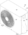
- outdoor unit 100 includes a housing 109 and a fan, a compressor, a heat exchanger, and the like inside housing 109.
- the housing 109 includes a front panel 101, a top panel 102, a side panel 103, a back panel, a bottom panel, and the like.
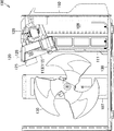
- partition plate 111 is erected on the side of fan 130 in casing 109.
- the partition plate 111 is a member for partitioning a space in which the fan 130 is disposed and a space 108 in which a compressor, an accumulator, an expansion valve, and the like are disposed.
- An electrical board 120 is disposed on the upper part of the partition plate 111.
- electrical board 120 is held in a state where the surface of electrical board 120 is inclined from the vertical direction toward fan 130.
- the surface of the electrical board 120 is preferably tilted from about 10 ° to 60 ° from the vertical direction, and is preferably tilted from about 15 ° to 40 ° in view of workability and space efficiency.
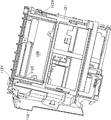
- the outer periphery of the electrical board 120 is fitted into the frame body 121.
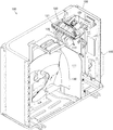
- a holding holder 112 for holding the electrical board 120 and the frame body 121 so as to be slidable in an oblique direction is fixed to the upper part of the partition plate 111 in a state of being inclined from the vertical direction toward the fan 130.
- the lower surface of the holding holder 112 is covered with the cover 113.
- the upper end portion of the partition plate 111 reaches a little higher than the right side of the rotation shaft of the fan 130.
- the lower end of the holding holder 112 is fixed to the upper end of the partition plate 111, and the upper end reaches the upper right of the fan 130.
- the upper end portion of the electrical board 120 is positioned on the upper right side of the fan 130 in a state where the electrical board 120 is inserted to the farthest, that is, the lowest position of the holding holder 112.
- Various electrical components such as main wiring, a microcomputer, a connector, and the like are attached to the electrical substrate 120 on the opposite surface of the fan 130. That is, in the present embodiment, the surface of the electrical board 120 opposite to the fan 130 is the surface. A plurality of heat dissipating plates 125, 125... As a result, heat generated on the surface of the electrical board 120 can be conducted to the heat radiating plates 125, 125... And efficiently radiated by the wind of the fan 130.
- the electrical board 120 is tilted from the vertical direction toward the fan 130 and is slidable obliquely upward.
- the degree of inclination of the electrical board 120 is preferably such that a serviceman can check the surface of the electrical board 120 from above the outdoor unit 100 and does not interfere with the fan 130.
- a service person opens the top panel 102, repairs the electrical board 120, easily removes the wiring from the connector on the surface of the electrical board 120, The board 120 itself can be slid obliquely upward and removed from the outdoor unit 100.
- the reactor 129 is disposed obliquely above and to the right of the electrical board 120.
- a shielding plate 128 is disposed between the electrical board 120 and the reactor 129. This makes it difficult for the heat generated in the reactor 129 to flow into the surface of the electrical substrate 120.
- shielding plate 128 includes an upper shielding plate 128A and a lower shielding plate 128B.
- the shielding plate 128 not only shields the space between the electrical board 120 and the space near the reactor 129 but also shields the space on the surface of the electrical board 120 from the back side and the front side of the outdoor unit 100. It is configured. 6, the frame body 121 or the holding holder 112 has exhaust ports 112X, 112X,... For allowing air on the inside of the shielding plate 128, that is, on the surface side of the electrical board 120, to flow toward the fan 130. Is formed, and an exhaust port 112Y through which air on the back side of the shielding plate 128, that is, air on the reactor 129 side flows toward the fan 130 is formed. This makes it difficult for the heat generated in the reactor 129 to flow into the surface of the electrical substrate 120, and most of the heat can flow directly to the fan 130 side.
- the holding holder 112 is covered with a cover 113.
- ventilation holes 113 ⁇ / b> X, 113 ⁇ / b> X... Are formed in the holding holder 112.
- the air that holds the heat generated in the electrical board 120 discharged from the exhaust ports 112X, 112X, and the air that holds the heat generated in the reactor 129 discharged from the exhaust port 112Y are supplied to the ventilation holes 113X, Flow from 113X to the fan 130 side.
- the exhaust ports 112X, 112X..., The exhaust ports 112Y, and the vent holes 113X, 113X It is formed in front of or behind the fan 130.
- the exhaust ports 112X, 112X,..., The exhaust ports 112Y, and the ventilation holes 113X, 113X Accordingly, even if water is blown sideways by the fan 130, the possibility of water adhering to the surface of the electrical board 120 can be reduced.
- the shielding plate 128 is configured in a gate shape when viewed from below, and is configured such that air flows into the surface of the electrical board 120 from below. Yes. This makes it difficult for air containing heat generated in the reactor 129 to flow into the surface of the electrical board 120.
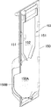
- the side cover 150 is attached to the side panel 103.
- the side cover 150 is formed such that a lower part 150A swells compared to the upper part, and an opening 150B is formed on the side of the lower part 150A.
- the refrigerant pipe from the indoor unit is connected to the two-way valve or the three-way valve of the outdoor unit 100.
- signal lines and the like from the indoor unit are extended upward from the inside of the lower part 150A.
- the signal line extends upward inside the partitions 151 and 151 and reaches from the upper part of the side panel 103 of the outdoor unit 100 to the inside of the outdoor unit 100. Note that the possibility of outside air entering the outdoor unit 100 along the signal line can be reduced by filling a sealant or the like around the signal line between the partitions 151 and 151.
- side panel 103 has an opening 103 ⁇ / b> A for passing the above-described refrigerant pipe formed in the lower portion thereof, and an opening 103 ⁇ / b> B for passing a signal line thereon. It is formed.
- the terminal block 141 is attached to the inner surface of the side panel 103 inside the opening 103B.
- the terminal block 141 is formed in a box shape, and openings are formed on the opening 103 ⁇ / b> B side of the side panel 103 and the electrical board 120 side.
- the terminal block 141 may be fixed to a portion where the side panel 103 is bent to the front side and the back side of the outdoor unit 100.
- the back side of the outdoor unit 100 in the terminal block 141 may be attached to a member that holds the reactor 129 or the like.
- FIG. 10 it is comprised so that the external air which flowed in the outer part of the partitions 151 and 151 out of the space inside the side cover 150 may flow from the opening part 150B. . Then, after entering the outdoor unit 100, the outside air flows outside the terminal block 141, passes through the fan 130, and is discharged from the outdoor unit 100.
- the terminal board 142 is disposed inside the terminal block 141.
- the terminal block 141, the side panel 103, the holding member of the reactor 129, and the like are configured so that water hardly adheres to the signal line passing through the terminal board 142. More specifically, when the terminal block 141 has a box shape as shown in FIG. 11, even if water intrudes from the gap between the side panel 103 and the upper panel 102 due to water pressure due to heavy rain or the like, Since 141 covers the charging unit, that is, the terminal board 142, the possibility that moisture directly adheres to the terminal board 142 can be reduced.
- the heat generated in the reactor 129 is not easily transmitted to the air passing through the terminal block 141. More specifically, the heat of the reactor 129 is absorbed by taking in the outside air in the flow of the side cover opening 150B ⁇ the outside of the side cover partition 151 ⁇ the outside of the terminal block 141 ⁇ the vicinity of the reactor 129 ⁇ the arrangement space of the fan 130. It will be pulled to the fan 130 side of the blower chamber on the downstream side, and heat is not easily transmitted to the terminal board 142 on the upstream side of the reactor 129.
- the partition plate 111 may further hold the electrical board 120 obliquely via another member.
- the electrical substrate 120 may be held obliquely by a member other than the partition plate 111.
- the shielding plate 128 includes the upper shielding plate 128A and the lower shielding plate 128B. And the lower part of the shielding board 128 is not restricted to the form opened completely as shown in FIG.
- the punching hole is preferably formed below the reactor 129. Accordingly, air that has not passed through the reactor 129 can be sent from the punching hole to the surface of the electrical board 120 while reducing water intrusion from below the shielding plate 128.
- the outdoor unit 100 of an air conditioner includes a housing 109, a fan 130 disposed in the housing 109, and an electrical board 120 disposed on the side of the fan 130.
- the electrical board 120 is held in a state where it is tilted in the direction of the fan 130 from a state in which it stands in the vertical direction.
- the outdoor unit 100 is erected on the side of the fan 130, and the partition member 111 for partitioning the space of the fan 130 and the space of the compressor, and the electrical board 120 in a direction inclined toward the fan 130.
- holding member 112 (113) for holding.
- the holding member 112 (113) is configured such that the electrical board 120 is slidable obliquely upward in parallel with the surface of the electrical board 120.
- the holding member 112 is formed with first exhaust ports 112X and 112X for discharging the heat on the front surface side of the electrical board 120 to the back surface.
- the first exhaust ports 112 ⁇ / b> X and 112 ⁇ / b> X are formed on the rear side or the front side with respect to the side of the fan 130.
- the outdoor unit 100 includes a reactor 129 disposed at a position separated from the electrical substrate 120 on the surface side of the electrical substrate 120, and a shielding plate 128 for partitioning the surface of the electrical substrate 120 and the reactor 129. Further prepare.
- the holding member 112 is formed with second exhaust ports 112Y and 112Y for discharging heat in the vicinity of the reactor 129 to the fan 130 side.
- a plurality of holes are formed in the shielding plate 128 below the reactor 129.
Landscapes
- Engineering & Computer Science (AREA)
- Chemical & Material Sciences (AREA)
- Combustion & Propulsion (AREA)
- Mechanical Engineering (AREA)
- General Engineering & Computer Science (AREA)
- Other Air-Conditioning Systems (AREA)
Abstract
L'invention concerne une unité extérieure (100) pour un climatiseur. L'unité extérieure (100) a un boîtier (109), un ventilateur (130) disposé à l'intérieur du boîtier (109) et une carte électrique (120) disposée à côté du ventilateur (130). La carte électrique (120) est maintenue de manière à être inclinée dans la direction du ventilateur (130) à partir d'un état dressé à la verticale.
Priority Applications (2)
| Application Number | Priority Date | Filing Date | Title |
|---|---|---|---|
| CN201980037966.3A CN112219068A (zh) | 2018-06-15 | 2019-02-06 | 室外机 |
| JP2020525233A JPWO2019239630A1 (ja) | 2018-06-15 | 2019-02-06 | 室外機 |
Applications Claiming Priority (2)
| Application Number | Priority Date | Filing Date | Title |
|---|---|---|---|
| JP2018114140 | 2018-06-15 | ||
| JP2018-114140 | 2018-06-15 |
Publications (1)
| Publication Number | Publication Date |
|---|---|
| WO2019239630A1 true WO2019239630A1 (fr) | 2019-12-19 |
Family
ID=68841790
Family Applications (1)
| Application Number | Title | Priority Date | Filing Date |
|---|---|---|---|
| PCT/JP2019/004237 Ceased WO2019239630A1 (fr) | 2018-06-15 | 2019-02-06 | Unité extérieure |
Country Status (3)
| Country | Link |
|---|---|
| JP (1) | JPWO2019239630A1 (fr) |
| CN (1) | CN112219068A (fr) |
| WO (1) | WO2019239630A1 (fr) |
Cited By (5)
| Publication number | Priority date | Publication date | Assignee | Title |
|---|---|---|---|---|
| CN111121177A (zh) * | 2019-12-25 | 2020-05-08 | 珠海格力电器股份有限公司 | 电器盒安装结构、室外机及空调器 |
| CN112197353A (zh) * | 2020-10-30 | 2021-01-08 | 广东美的制冷设备有限公司 | 空调室外机及空调器 |
| JP2023080693A (ja) * | 2021-11-30 | 2023-06-09 | ダイキン工業株式会社 | 空気調和装置 |
| WO2024053595A1 (fr) * | 2022-09-09 | 2024-03-14 | ダイキン工業株式会社 | Dispositif de climatisation |
| EP4495493A4 (fr) * | 2022-03-18 | 2026-03-18 | Fujitsu General Ltd | Unité extérieure de dispositif à cycle de pompe à chaleur et dispositif à cycle de pompe à chaleur |
Citations (9)
| Publication number | Priority date | Publication date | Assignee | Title |
|---|---|---|---|---|
| JPH0178830U (fr) * | 1987-11-18 | 1989-05-26 | ||
| JPH0544961A (ja) * | 1991-08-08 | 1993-02-23 | Matsushita Electric Ind Co Ltd | 空気調和機 |
| JPH0579661A (ja) * | 1991-09-19 | 1993-03-30 | Mitsubishi Electric Corp | 空気調和機の室外ユニツト及びその電気品装置 |
| JPH07305871A (ja) * | 1994-05-13 | 1995-11-21 | Sanyo Electric Co Ltd | 空気調和機用室外ユニットの端子基板 |
| JPH09236283A (ja) * | 1996-02-29 | 1997-09-09 | Daikin Ind Ltd | 空気調和機用室外機 |
| JPH10227489A (ja) * | 1997-02-13 | 1998-08-25 | Mitsubishi Electric Corp | 空気調和機の室外ユニット |
| JP2008281286A (ja) * | 2007-05-11 | 2008-11-20 | Hitachi Appliances Inc | 空気調和機の室外機 |
| JP2012159223A (ja) * | 2011-01-31 | 2012-08-23 | Fujitsu General Ltd | 空気調和機の室外機 |
| JP2012233614A (ja) * | 2011-04-28 | 2012-11-29 | Sanyo Electric Co Ltd | 空気調和装置の室外ユニット |
Family Cites Families (3)
| Publication number | Priority date | Publication date | Assignee | Title |
|---|---|---|---|---|
| CN202056984U (zh) * | 2010-12-17 | 2011-11-30 | 广州松下空调器有限公司 | 空调器 |
| CN203431999U (zh) * | 2013-08-07 | 2014-02-12 | 江森自控空调冷冻设备(无锡)有限公司 | 空调室外机控制箱、空调室外机和空调 |
| CN105698287B (zh) * | 2016-03-01 | 2018-06-29 | 广东志高空调有限公司 | 一种空调室外机的电气板组件 |
-
2019
- 2019-02-06 JP JP2020525233A patent/JPWO2019239630A1/ja active Pending
- 2019-02-06 CN CN201980037966.3A patent/CN112219068A/zh active Pending
- 2019-02-06 WO PCT/JP2019/004237 patent/WO2019239630A1/fr not_active Ceased
Patent Citations (9)
| Publication number | Priority date | Publication date | Assignee | Title |
|---|---|---|---|---|
| JPH0178830U (fr) * | 1987-11-18 | 1989-05-26 | ||
| JPH0544961A (ja) * | 1991-08-08 | 1993-02-23 | Matsushita Electric Ind Co Ltd | 空気調和機 |
| JPH0579661A (ja) * | 1991-09-19 | 1993-03-30 | Mitsubishi Electric Corp | 空気調和機の室外ユニツト及びその電気品装置 |
| JPH07305871A (ja) * | 1994-05-13 | 1995-11-21 | Sanyo Electric Co Ltd | 空気調和機用室外ユニットの端子基板 |
| JPH09236283A (ja) * | 1996-02-29 | 1997-09-09 | Daikin Ind Ltd | 空気調和機用室外機 |
| JPH10227489A (ja) * | 1997-02-13 | 1998-08-25 | Mitsubishi Electric Corp | 空気調和機の室外ユニット |
| JP2008281286A (ja) * | 2007-05-11 | 2008-11-20 | Hitachi Appliances Inc | 空気調和機の室外機 |
| JP2012159223A (ja) * | 2011-01-31 | 2012-08-23 | Fujitsu General Ltd | 空気調和機の室外機 |
| JP2012233614A (ja) * | 2011-04-28 | 2012-11-29 | Sanyo Electric Co Ltd | 空気調和装置の室外ユニット |
Cited By (9)
| Publication number | Priority date | Publication date | Assignee | Title |
|---|---|---|---|---|
| CN111121177A (zh) * | 2019-12-25 | 2020-05-08 | 珠海格力电器股份有限公司 | 电器盒安装结构、室外机及空调器 |
| CN112197353A (zh) * | 2020-10-30 | 2021-01-08 | 广东美的制冷设备有限公司 | 空调室外机及空调器 |
| CN112197353B (zh) * | 2020-10-30 | 2025-08-22 | 广东美的制冷设备有限公司 | 空调室外机及空调器 |
| JP2023080693A (ja) * | 2021-11-30 | 2023-06-09 | ダイキン工業株式会社 | 空気調和装置 |
| JP7502657B2 (ja) | 2021-11-30 | 2024-06-19 | ダイキン工業株式会社 | 空気調和装置 |
| EP4495493A4 (fr) * | 2022-03-18 | 2026-03-18 | Fujitsu General Ltd | Unité extérieure de dispositif à cycle de pompe à chaleur et dispositif à cycle de pompe à chaleur |
| WO2024053595A1 (fr) * | 2022-09-09 | 2024-03-14 | ダイキン工業株式会社 | Dispositif de climatisation |
| JP7587163B2 (ja) | 2022-09-09 | 2024-11-20 | ダイキン工業株式会社 | 空気調和装置 |
| CN119816692A (zh) * | 2022-09-09 | 2025-04-11 | 大金工业株式会社 | 空调装置 |
Also Published As
| Publication number | Publication date |
|---|---|
| JPWO2019239630A1 (ja) | 2021-06-24 |
| CN112219068A (zh) | 2021-01-12 |
Similar Documents
| Publication | Publication Date | Title |
|---|---|---|
| WO2019239630A1 (fr) | Unité extérieure | |
| CN106796038A (zh) | 空气调节机的室外机 | |
| CN101292120A (zh) | 截止阀支撑部件及具有该部件的空调装置的室外单元 | |
| JP6123585B2 (ja) | 空気調和機の室外機 | |
| JP2011094889A (ja) | ダクト型空気調和機 | |
| JP6661757B2 (ja) | 空気調和機の室外機 | |
| JP5873994B2 (ja) | 空気調和装置の室外ユニット | |
| EP1956310A1 (fr) | Ensemble composant electrique et unite exterieure de climatiseur ainsi equipe | |
| JP2010054168A (ja) | 空気調和機の室外機 | |
| CN102141275B (zh) | 空气调节装置的室外单元 | |
| CN103912926B (zh) | 室外单元 | |
| KR20180065725A (ko) | 공기 조화기의 실외기 | |
| CN101087979B (zh) | 空调装置的室外机 | |
| JP2014105948A (ja) | 空気調和機の室外機 | |
| JP5877359B2 (ja) | 空気調和装置の室外ユニット | |
| CN202835596U (zh) | 制冷装置的室外机组 | |
| CN203533736U (zh) | 空调装置的室外机 | |
| JP2009174827A (ja) | 室外機及びこれを備えた空気調和機 | |
| JP2012141069A (ja) | ダクト型空気調和機の室内機 | |
| CN113614466B (zh) | 空调机的室内单元 | |
| JP2008298346A (ja) | 電装品ユニット | |
| KR20180065724A (ko) | 공기 조화기의 실외기 | |
| KR20180065723A (ko) | 공기 조화기의 실외기 | |
| JP6974754B2 (ja) | 冷凍装置の室外機 | |
| JP4807244B2 (ja) | 空気調和装置の室外機 |
Legal Events
| Date | Code | Title | Description |
|---|---|---|---|
| 121 | Ep: the epo has been informed by wipo that ep was designated in this application |
Ref document number: 19819622 Country of ref document: EP Kind code of ref document: A1 |
|
| ENP | Entry into the national phase |
Ref document number: 2020525233 Country of ref document: JP Kind code of ref document: A |
|
| NENP | Non-entry into the national phase |
Ref country code: DE |
|
| 122 | Ep: pct application non-entry in european phase |
Ref document number: 19819622 Country of ref document: EP Kind code of ref document: A1 |