WO2019239948A1 - Batterie secondaire à électrolyte non aqueux - Google Patents
Batterie secondaire à électrolyte non aqueux Download PDFInfo
- Publication number
- WO2019239948A1 WO2019239948A1 PCT/JP2019/022065 JP2019022065W WO2019239948A1 WO 2019239948 A1 WO2019239948 A1 WO 2019239948A1 JP 2019022065 W JP2019022065 W JP 2019022065W WO 2019239948 A1 WO2019239948 A1 WO 2019239948A1
- Authority
- WO
- WIPO (PCT)
- Prior art keywords
- negative electrode
- graphite particles
- active material
- electrode active
- produced
- Prior art date
- Legal status (The legal status is an assumption and is not a legal conclusion. Google has not performed a legal analysis and makes no representation as to the accuracy of the status listed.)
- Ceased
Links
Images

Classifications
-
- H—ELECTRICITY
- H01—ELECTRIC ELEMENTS
- H01M—PROCESSES OR MEANS, e.g. BATTERIES, FOR THE DIRECT CONVERSION OF CHEMICAL ENERGY INTO ELECTRICAL ENERGY
- H01M4/00—Electrodes
- H01M4/02—Electrodes composed of, or comprising, active material
- H01M4/36—Selection of substances as active materials, active masses, active liquids
- H01M4/58—Selection of substances as active materials, active masses, active liquids of inorganic compounds other than oxides or hydroxides, e.g. sulfides, selenides, tellurides, halogenides or LiCoFy; of polyanionic structures, e.g. phosphates, silicates or borates
- H01M4/583—Carbonaceous material, e.g. graphite-intercalation compounds or CFx
- H01M4/587—Carbonaceous material, e.g. graphite-intercalation compounds or CFx for inserting or intercalating light metals
-
- H—ELECTRICITY
- H01—ELECTRIC ELEMENTS
- H01M—PROCESSES OR MEANS, e.g. BATTERIES, FOR THE DIRECT CONVERSION OF CHEMICAL ENERGY INTO ELECTRICAL ENERGY
- H01M4/00—Electrodes
- H01M4/02—Electrodes composed of, or comprising, active material
- H01M4/13—Electrodes for accumulators with non-aqueous electrolyte, e.g. for lithium-accumulators; Processes of manufacture thereof
- H01M4/133—Electrodes based on carbonaceous material, e.g. graphite-intercalation compounds or CFx
-
- H—ELECTRICITY
- H01—ELECTRIC ELEMENTS
- H01M—PROCESSES OR MEANS, e.g. BATTERIES, FOR THE DIRECT CONVERSION OF CHEMICAL ENERGY INTO ELECTRICAL ENERGY
- H01M4/00—Electrodes
- H01M4/02—Electrodes composed of, or comprising, active material
- H01M4/62—Selection of inactive substances as ingredients for active masses, e.g. binders, fillers
- H01M4/628—Inhibitors, e.g. gassing inhibitors, corrosion inhibitors
-
- H—ELECTRICITY
- H01—ELECTRIC ELEMENTS
- H01M—PROCESSES OR MEANS, e.g. BATTERIES, FOR THE DIRECT CONVERSION OF CHEMICAL ENERGY INTO ELECTRICAL ENERGY
- H01M10/00—Secondary cells; Manufacture thereof
- H01M10/05—Accumulators with non-aqueous electrolyte
-
- H—ELECTRICITY
- H01—ELECTRIC ELEMENTS
- H01M—PROCESSES OR MEANS, e.g. BATTERIES, FOR THE DIRECT CONVERSION OF CHEMICAL ENERGY INTO ELECTRICAL ENERGY
- H01M4/00—Electrodes
- H01M4/02—Electrodes composed of, or comprising, active material
- H01M4/36—Selection of substances as active materials, active masses, active liquids
- H01M4/362—Composites
- H01M4/364—Composites as mixtures
-
- H—ELECTRICITY
- H01—ELECTRIC ELEMENTS
- H01M—PROCESSES OR MEANS, e.g. BATTERIES, FOR THE DIRECT CONVERSION OF CHEMICAL ENERGY INTO ELECTRICAL ENERGY
- H01M4/00—Electrodes
- H01M4/02—Electrodes composed of, or comprising, active material
- H01M4/36—Selection of substances as active materials, active masses, active liquids
- H01M4/362—Composites
- H01M4/366—Composites as layered products
-
- H—ELECTRICITY
- H01—ELECTRIC ELEMENTS
- H01M—PROCESSES OR MEANS, e.g. BATTERIES, FOR THE DIRECT CONVERSION OF CHEMICAL ENERGY INTO ELECTRICAL ENERGY
- H01M4/00—Electrodes
- H01M4/02—Electrodes composed of, or comprising, active material
- H01M4/36—Selection of substances as active materials, active masses, active liquids
- H01M4/38—Selection of substances as active materials, active masses, active liquids of elements or alloys
-
- H—ELECTRICITY
- H01—ELECTRIC ELEMENTS
- H01M—PROCESSES OR MEANS, e.g. BATTERIES, FOR THE DIRECT CONVERSION OF CHEMICAL ENERGY INTO ELECTRICAL ENERGY
- H01M4/00—Electrodes
- H01M4/02—Electrodes composed of, or comprising, active material
- H01M4/62—Selection of inactive substances as ingredients for active masses, e.g. binders, fillers
- H01M4/624—Electric conductive fillers
- H01M4/625—Carbon or graphite
-
- H—ELECTRICITY
- H01—ELECTRIC ELEMENTS
- H01M—PROCESSES OR MEANS, e.g. BATTERIES, FOR THE DIRECT CONVERSION OF CHEMICAL ENERGY INTO ELECTRICAL ENERGY
- H01M10/00—Secondary cells; Manufacture thereof
- H01M10/05—Accumulators with non-aqueous electrolyte
- H01M10/052—Li-accumulators
- H01M10/0525—Rocking-chair batteries, i.e. batteries with lithium insertion or intercalation in both electrodes; Lithium-ion batteries
-
- H—ELECTRICITY
- H01—ELECTRIC ELEMENTS
- H01M—PROCESSES OR MEANS, e.g. BATTERIES, FOR THE DIRECT CONVERSION OF CHEMICAL ENERGY INTO ELECTRICAL ENERGY
- H01M4/00—Electrodes
- H01M4/02—Electrodes composed of, or comprising, active material
- H01M2004/021—Physical characteristics, e.g. porosity, surface area
-
- H—ELECTRICITY
- H01—ELECTRIC ELEMENTS
- H01M—PROCESSES OR MEANS, e.g. BATTERIES, FOR THE DIRECT CONVERSION OF CHEMICAL ENERGY INTO ELECTRICAL ENERGY
- H01M4/00—Electrodes
- H01M4/02—Electrodes composed of, or comprising, active material
- H01M2004/026—Electrodes composed of, or comprising, active material characterised by the polarity
- H01M2004/027—Negative electrodes
-
- Y—GENERAL TAGGING OF NEW TECHNOLOGICAL DEVELOPMENTS; GENERAL TAGGING OF CROSS-SECTIONAL TECHNOLOGIES SPANNING OVER SEVERAL SECTIONS OF THE IPC; TECHNICAL SUBJECTS COVERED BY FORMER USPC CROSS-REFERENCE ART COLLECTIONS [XRACs] AND DIGESTS
- Y02—TECHNOLOGIES OR APPLICATIONS FOR MITIGATION OR ADAPTATION AGAINST CLIMATE CHANGE
- Y02E—REDUCTION OF GREENHOUSE GAS [GHG] EMISSIONS, RELATED TO ENERGY GENERATION, TRANSMISSION OR DISTRIBUTION
- Y02E60/00—Enabling technologies; Technologies with a potential or indirect contribution to GHG emissions mitigation
- Y02E60/10—Energy storage using batteries
Definitions
- This disclosure relates to a non-aqueous electrolyte secondary battery.
- Non-aqueous electrolyte secondary batteries using a carbon material as a negative electrode active material are widely used as high energy density secondary batteries.
- Patent Document 1 discloses a non-aqueous electrolyte secondary battery using densified carbon having an internal porosity of 5% or less as a carbon material.
- Patent Document 2 discloses a non-aqueous electrolyte 2 using a carbon material including a carbon material A having an internal porosity of 1% to less than 23% and a carbon material B having an internal porosity of 23% to 40%.
- a secondary battery is disclosed.
- the negative electrode of a nonaqueous electrolyte secondary battery is obtained by applying and drying a slurry containing a carbon material as a negative electrode active material on a negative electrode current collector, and compressing the obtained coating film (negative electrode active material layer).
- a negative electrode active material layer having a high packing density cannot be obtained unless the compression is performed a plurality of times. An increase in the number of man-hours in the compression process may lead to a decrease in battery productivity.
- an object of the present disclosure is to provide a non-aqueous electrolyte secondary battery that can suppress an increase in the number of man-hours in the compression process in the manufacture of the negative electrode and can suppress a decrease in charge / discharge cycle characteristics.
- a nonaqueous electrolyte secondary battery which is one embodiment of the present disclosure includes a negative electrode having a negative electrode active material layer, and the negative electrode active material layer includes graphite particles A and graphite particles B as a negative electrode active material, and the graphite particles A
- the internal porosity of the graphite particles B is 8% to 20%, and the mass ratio of the graphite particles A to the graphite particles B is 70:30 to 90:10. is there.
- non-aqueous electrolyte secondary battery that can suppress an increase in the number of man-hours in the compression process in negative electrode production and suppress a decrease in charge / discharge cycle characteristics.
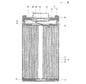
- FIG. 1 is a cross-sectional view of a nonaqueous electrolyte secondary battery which is an example of an embodiment.
- FIG. 2 is a schematic enlarged view showing a cross section of the graphite particles in the negative electrode active material layer.
- graphite particles with a low internal porosity suppress the destruction of the graphite particles in the charge / discharge cycle and the accompanying decomposition reaction of the nonaqueous electrolyte. There exists a tendency for the fall of the charging / discharging cycling characteristics of a battery to be suppressed.
- the graphite particles having a low internal porosity are not easily crushed by compression, a negative electrode active material layer having a high packing density cannot be obtained unless the above-described compression in the production of the negative electrode is performed a plurality of times.
- a nonaqueous electrolyte secondary battery which is one embodiment of the present disclosure includes a negative electrode having a negative electrode active material layer, and the negative electrode active material layer includes graphite particles A and graphite particles B as a negative electrode active material, and the graphite particles A
- the internal porosity of the graphite particles B is 8% to 20%, and the mass ratio of the graphite particles A to the graphite particles B is 70:30 to 90:10. It is characterized by a mass ratio.
- a negative electrode active material layer containing graphite particles A having an internal porosity of 5% or less and graphite particles B having an internal porosity of 8% to 20% in a mass ratio of 70:30 to 90:10 is produced.
- the graphite particles B are appropriately crushed and interposed in the gaps between the graphite particles A that are not easily crushed, so that the packing density is high without increasing the number of steps in the compression process. Easy to be. If the ratio of the graphite particles A exceeds the above range, the gap between the graphite particles A does not decrease unless the number of man-hours in the compression process is increased, so that a high packing density cannot be obtained.
- the presence of the graphite particles A having an internal porosity of 5% or less in the negative electrode active material layer in the above ratio suppresses a decrease in charge / discharge cycle characteristics.
- the graphite particle B is interposed in the space between the graphite particles A as described above. Therefore, it is considered that one of the causes is that the contact ratio between the graphite particles (A, B) is improved.
- the graphite particles B having an internal void of 8% to 20% have a high nonaqueous electrolyte retention amount, the presence of the graphite particles B in the negative electrode active material layer results in a certain amount in the negative electrode active material layer.
- one of the causes is that the nonaqueous electrolyte is retained and a sufficient amount of contact between the graphite particles (A, B) and the nonaqueous electrolyte is ensured.
- the ratio of the graphite particles B exceeds the above range, the destruction of the graphite particles in the charge / discharge cycle, the accompanying decomposition reaction of the nonaqueous electrolyte, etc. increase, and the deterioration of the charge / discharge cycle characteristics can be sufficiently suppressed. It becomes difficult.
- nonaqueous electrolyte secondary battery of this indication is not limited to embodiment described below.
- the drawings referred to in the description of the embodiments are schematically described.
- FIG. 1 is a cross-sectional view of a nonaqueous electrolyte secondary battery which is an example of an embodiment.
- a non-aqueous electrolyte secondary battery 10 shown in FIG. 1 includes a wound electrode body 14 in which a positive electrode 11 and a negative electrode 12 are wound via a separator 13, a non-aqueous electrolyte, and an electrode body 14 above and below, respectively. Insulating plates 18 and 19 disposed, and a battery case 15 that accommodates the members are provided.
- the battery case 15 includes a bottomed cylindrical case body 16 and a sealing body 17 that closes an opening of the case body 16.
- the wound electrode body 14 other forms of electrode bodies such as a stacked electrode body in which positive and negative electrodes are alternately stacked via separators may be applied.
- the battery case 15 include a metal outer can such as a cylindrical shape, a square shape, a coin shape, and a button shape, and a pouch outer case formed by laminating a resin sheet and a metal sheet.
- the case body 16 is, for example, a bottomed cylindrical metal outer can.
- a gasket 28 is provided between the case main body 16 and the sealing body 17 to ensure the sealing inside the battery.
- the case main body 16 includes, for example, an overhanging portion 22 that supports the sealing body 17 in which a part of the side surface portion protrudes inward.
- the overhang portion 22 is preferably formed in an annular shape along the circumferential direction of the case body 16, and supports the sealing body 17 on its upper surface.
- the sealing body 17 has a structure in which a filter 23, a lower valve body 24, an insulating member 25, an upper valve body 26, and a cap 27 are laminated in this order from the electrode body 14 side.
- Each member which comprises the sealing body 17 has disk shape or a ring shape, for example, and each member except the insulating member 25 is electrically connected mutually.
- the lower valve body 24 and the upper valve body 26 are connected to each other at the center, and an insulating member 25 is interposed between the peripheral edges.
- the lower valve body 24 When the internal pressure of the non-aqueous electrolyte secondary battery 10 rises due to heat generation due to an internal short circuit or the like, the lower valve body 24 is deformed and broken, for example, so as to push the upper valve body 26 toward the cap 27, so The current path between the bodies 26 is interrupted. When the internal pressure further increases, the upper valve body 26 is broken and the gas is discharged from the opening of the cap 27.
- the positive electrode lead 20 attached to the positive electrode 11 extends through the through hole of the insulating plate 18 to the sealing body 17 side, and the negative electrode lead 21 attached to the negative electrode 12 is insulated.
- the case 19 extends to the bottom side of the case body 16 through the outside of the plate 19.
- the positive electrode lead 20 is connected to the lower surface of the filter 23 which is the bottom plate of the sealing body 17 by welding or the like, and the cap 27 which is the top plate of the sealing body 17 electrically connected to the filter 23 serves as a positive electrode terminal.
- the negative electrode lead 21 is connected to the bottom inner surface of the case main body 16 by welding or the like, and the case main body 16 serves as a negative electrode terminal.
- the negative electrode 12 includes a negative electrode current collector made of, for example, a metal foil, and a negative electrode active material layer formed on the current collector.
- a negative electrode current collector for example, a metal foil that is stable in the potential range of a negative electrode such as copper, a film in which the metal is disposed on the surface layer, or the like is used.
- the negative electrode active material layer includes a negative electrode active material containing graphite particles.
- the negative electrode active material layer preferably contains a binder or the like.
- FIG. 2 is a schematic enlarged view showing a cross section of the graphite particles in the negative electrode active material layer.
- the graphite particles 30 are connected to the closed voids 34 (hereinafter referred to as internal voids 34) that are not connected from the inside of the particles to the particle surface and from the inside of the particles to the particle surface in a cross-sectional view of the graphite particles 30.
- a gap 36 (hereinafter referred to as an external gap 36).
- the graphite particles 30 in the present embodiment include graphite particles A having an internal porosity of 5% or less and graphite particles B having an internal porosity of 8% to 20%.
- the internal porosity of the graphite particles A may be 5% or less from the viewpoint of suppressing a decrease in charge / discharge cycle characteristics, but is preferably 1% to 5%, more preferably 3% to 5%. It is.
- the internal porosity of the graphite particles B may be 8% to 20% in terms of facilitating the compression of the negative electrode active material layer, but is preferably 10% to 18%, more preferably 12%. ⁇ 16%.
- the internal porosity of the graphite particles is a two-dimensional value obtained from the ratio of the area of the internal voids 34 of the graphite particles to the cross-sectional area of the graphite particles. And the internal porosity of a graphite particle is calculated
- ⁇ Measurement method of internal porosity> (1) The cross section of the negative electrode active material is exposed. Examples of the method for exposing the cross section include a method in which a part of the negative electrode is cut out and processed with an ion milling device (for example, IM4000PLUS, manufactured by Hitachi High-Tech) to expose the cross section of the negative electrode active material layer. (2) A backscattered electron image of the cross section of the exposed negative electrode active material layer is taken using a scanning electron microscope. The magnification at the time of taking a reflected electron image is 3,000 to 5,000 times.
- an ion milling device for example, IM4000PLUS, manufactured by Hitachi High-Tech
- the area of the graphite particle cross section refers to the area of the region surrounded by the outer periphery of the graphite particle, that is, the area of the entire cross section of the graphite particle. Further, among the voids present in the cross section of the graphite particle, the void having a width of 3 ⁇ m or less may be difficult to distinguish between the internal void and the external void in the image analysis. It is good. Then, from the calculated area of the graphite particle cross section and the area of the internal void of the graphite particle cross section, the internal porosity of the graphite particle (area of the internal void of the graphite particle cross section ⁇ 100 / area of the graphite particle cross section) is calculated. The internal porosity of the graphite particles A and B is an average value of 10 graphite particles A and B, respectively.
- the graphite particles A and B are manufactured as follows, for example. ⁇ Graphite particles A having an internal porosity of 5% or less> For example, coke (precursor) as a main raw material is pulverized to a predetermined size, and in a state where they are aggregated with a binder, fired at a temperature of 2600 ° C. or more, graphitized, and then sieved. Graphite particles A having a desired size are obtained.
- the internal porosity can be adjusted to 5% or less depending on the particle size of the pulverized precursor, the particle size of the aggregated precursor, and the like.
- the average particle diameter (median diameter D50) of the pulverized precursor is preferably in the range of 12 ⁇ m to 20 ⁇ m.
- ⁇ Graphite particles B having an internal porosity of 8% to 20%> coke (precursor) as a main raw material is pulverized to a predetermined size, aggregated with a binder, and further calcined at a temperature of 2600 ° C. or more in a state of being pressure-molded into a block shape, and graphitized.
- the block-shaped formed body after graphitization is pulverized and sieved to obtain graphite particles B having a desired size.
- the internal porosity can be adjusted to 8% to 20% depending on the amount of the volatile component added to the block-shaped molded body.
- the binder can be used as a volatile component.
- a pitch is illustrated as such a binder.
- the graphite particles A and B used in the present embodiment are not particularly limited, such as natural graphite and artificial graphite, but artificial graphite is preferable in terms of easy adjustment of the internal porosity.
- the interplanar spacing (d 002 ) of the (002) plane of the graphite particles A and B used in the present embodiment by the X-ray wide angle diffraction method is preferably, for example, 0.3354 nm or more, and 0.3357 nm or more. Is more preferable, and it is preferably less than 0.340 nm, and more preferably 0.338 nm or less.
- the crystallite size (Lc (002)) obtained by the X-ray diffraction method of the graphite particles A and B used in the present embodiment is, for example, preferably 5 nm or more, and more preferably 10 nm or more. Moreover, it is preferable that it is 300 nm or less, and it is more preferable that it is 200 nm or less.
- the interplanar spacing (d 002 ) and the crystallite size (Lc (002)) satisfy the above range, the battery capacity of the nonaqueous electrolyte secondary battery tends to be larger than when the above range is not satisfied.
- the negative electrode 12 is prepared, for example, by preparing a negative electrode mixture slurry containing a negative electrode active material containing graphite particles A and B, a binder, etc., and applying and drying the negative electrode mixture slurry on a negative electrode current collector. After forming a material layer, it can produce by performing the compression process which compresses a negative electrode active material layer with a rolling roller etc.
- the negative electrode active material contains graphite particles A and graphite particles B in a mass ratio of 70:30 to 90:10. Further, as described above, the negative electrode active material layer in which the mass ratio of the graphite particles A and the graphite particles B is in the above range is likely to have a high packing density due to compression of a rolling roller or the like.
- the mass ratio of the graphite particles A and the graphite particles B is preferably 70:30 to 85:15 from the viewpoint that a high packing density can be obtained without increasing the number of steps in the compression step in the production of the negative electrode. More preferably, it is 70:30 to 80:20.
- the packing density of the negative electrode active material layer in terms of such obtain secure and good battery characteristics of the intensity of the negative electrode active material layer is preferably 1.2g / cm 3 ⁇ 1.7g / cm 3, 1. More preferably, it is 5 g / cm 3 to 1.7 g / cm 3 .
- the mass ratio of graphite particles A / graphite particles B exceeds 90/10, the packing density in the above range can be increased unless the man-hours in the compression process of the negative electrode active material layer are increased compared to the case of 90/10 or less. It is not possible to obtain a negative electrode active material layer.
- the mass ratio of the graphite particles A / graphite particles B is less than 70/30, compared with the case of 70/30 or more, the number of steps in the compression step of the negative electrode active material layer is not increased, and the above range. Although it is possible to obtain a negative electrode active material layer having a packing density, charge / discharge cycle characteristics are deteriorated.
- the negative electrode active material may contain other materials capable of reversibly occluding and releasing lithium ions, such as silicon (Si) and tin (Sn).
- a metal such as an alloy with lithium, or an alloy containing a metal element such as Si or Sn, an oxide, or the like may be included. If the content of the other material is increased, the effect of suppressing the deterioration of the charge / discharge cycle characteristics of the nonaqueous electrolyte secondary battery may not be sufficiently obtained, so the content of the other material is, for example, It is desirable to set it as 10 mass% or less with respect to the mass of a negative electrode active material.
- binder examples include fluorine resin, PAN, polyimide resin, acrylic resin, polyolefin resin, styrene-butadiene rubber (SBR), carboxymethyl cellulose (CMC) or a salt thereof, polyacrylic acid (PAA) or Examples thereof include PAA-Na, PAA-K, and the like, and may be partially neutralized salts, polyvinyl alcohol (PVA), and the like. These may be used alone or in combination of two or more.
- the positive electrode 11 includes a positive electrode current collector such as a metal foil and a positive electrode active material layer formed on the positive electrode current collector.
- a positive electrode current collector such as a metal foil and a positive electrode active material layer formed on the positive electrode current collector.
- a metal foil that is stable in the potential range of the positive electrode such as aluminum, a film in which the metal is disposed on the surface layer, or the like can be used.
- the positive electrode active material layer includes, for example, a positive electrode active material, a binder, a conductive material, and the like.
- the positive electrode 11 is formed by, for example, applying a positive electrode mixture slurry containing a positive electrode active material, a binder, a conductive material, etc. on a positive electrode current collector and drying it to form a positive electrode active material layer, and then using a rolling roller or the like. It can produce by performing the compression process which compresses a positive electrode active material layer.
- Examples of the positive electrode active material include lithium transition metal oxides containing transition metal elements such as Co, Mn, and Ni.
- Examples of the lithium transition metal oxide include Li x CoO 2 , Li x NiO 2 , Li x MnO 2 , Li x Co y Ni 1-y O 2 , Li x Co y M 1-y O z , Li x Ni 1-1.
- the positive electrode active materials include Li x NiO 2 , Li x Co y Ni 1-y O 2 , and Li x Ni 1-y M y O z (wherein the capacity of the nonaqueous electrolyte secondary battery can be increased.
- M at least one of Na, Mg, Sc, Y, Mn, Fe, Co, Ni, Cu, Zn, Al, Cr, Pb, Sb, B, 0 ⁇ x ⁇ 1.2, 0 ⁇ y ⁇ 0 0.9, 2.0 ⁇ z ⁇ 2.3) and the like.
- Examples of the conductive material include carbon-based particles such as carbon black (CB), acetylene black (AB), ketjen black, and graphite. These may be used alone or in combination of two or more.
- CB carbon black
- AB acetylene black
- ketjen black ketjen black
- graphite graphite
- binder examples include fluorine resins such as polytetrafluoroethylene (PTFE) and polyvinylidene fluoride (PVdF), polyacrylonitrile (PAN), polyimide resins, acrylic resins, and polyolefin resins. These may be used alone or in combination of two or more.
- fluorine resins such as polytetrafluoroethylene (PTFE) and polyvinylidene fluoride (PVdF), polyacrylonitrile (PAN), polyimide resins, acrylic resins, and polyolefin resins. These may be used alone or in combination of two or more.
- the separator 13 for example, a porous sheet having ion permeability and insulating properties is used. Specific examples of the porous sheet include a microporous thin film, a woven fabric, and a nonwoven fabric.
- olefinic resins such as polyethylene and polypropylene, cellulose and the like are suitable.
- the separator 13 may be a laminate having a cellulose fiber layer and a thermoplastic resin fiber layer such as an olefin resin.
- the multilayer separator containing a polyethylene layer and a polypropylene layer may be sufficient, and what applied materials, such as an aramid resin and a ceramic, to the surface of a separator may be used.
- the non-aqueous electrolyte includes a non-aqueous solvent and an electrolyte salt dissolved in the non-aqueous solvent.
- the non-aqueous electrolyte is not limited to a liquid electrolyte (electrolytic solution), and may be a solid electrolyte using a gel polymer or the like.
- the non-aqueous solvent for example, esters, ethers, nitriles such as acetonitrile, amides such as dimethylformamide, and a mixed solvent of two or more of these can be used.
- the non-aqueous solvent may contain a halogen-substituted product in which at least a part of hydrogen in these solvents is substituted with a halogen atom such as fluorine.
- esters examples include cyclic carbonates such as ethylene carbonate (EC), propylene carbonate (PC) and butylene carbonate, dimethyl carbonate (DMC), ethyl methyl carbonate (EMC), diethyl carbonate (DEC), and methyl propyl carbonate.
- Chain carbonates such as ethyl propyl carbonate and methyl isopropyl carbonate
- cyclic carboxylic acid esters such as ⁇ -butyrolactone and ⁇ -valerolactone, methyl acetate, ethyl acetate, propyl acetate, methyl propionate (MP), ethyl propionate, Examples thereof include chain carboxylic acid esters such as ⁇ -butyrolactone.
- ethers examples include 1,3-dioxolane, 4-methyl-1,3-dioxolane, tetrahydrofuran, 2-methyltetrahydrofuran, propylene oxide, 1,2-butylene oxide, 1,3-dioxane, 1,4 -Cyclic ethers such as dioxane, 1,3,5-trioxane, furan, 2-methylfuran, 1,8-cineol, crown ether, 1,2-dimethoxyethane, diethyl ether, dipropyl ether, diisopropyl ether, dibutyl ether , Dihexyl ether, ethyl vinyl ether, butyl vinyl ether, methyl phenyl ether, ethyl phenyl ether, butyl phenyl ether, pentyl phenyl ether, methoxy toluene, benzyl ethyl ether, diphenyl ether, diphen
- a fluorinated cyclic carbonate such as fluoroethylene carbonate (FEC), a fluorinated chain carbonate, a fluorinated chain carboxylate such as methyl fluoropropionate (FMP), or the like.
- FEC fluoroethylene carbonate
- FMP fluorinated chain carboxylate
- FEC fluoroethylene carbonate
- FMP fluorinated chain carboxylate
- the electrolyte salt is preferably a lithium salt.
- the lithium salt LiBF 4, LiClO 4, LiPF 6, LiAsF 6, LiSbF 6, LiAlCl 4, LiSCN, LiCF 3 SO 3, LiCF 3 CO 2, Li (P (C 2 O 4) F 4), LiPF 6-x (C n F 2n + 1 ) x (1 ⁇ x ⁇ 6, n is 1 or 2), LiB 10 Cl 10 , LiCl, LiBr, LiI, lithium chloroborane, lithium lower aliphatic carboxylate, Li 2 B Borates such as 4 O 7 and Li (B (C 2 O 4 ) F 2 ), LiN (SO 2 CF 3 ) 2 , LiN (C 1 F 2l + 1 SO 2 ) (C m F 2m + 1 SO 2 ) ⁇ l , M is an integer greater than or equal to 1 ⁇ and the like.
- lithium salts may be used alone or in combination of two or more.
- LiPF 6 is preferably used from the viewpoints of ion conductivity, electrochemical stability, and the like.
- concentration of the lithium salt is preferably 0.8 to 1.8 mol per liter of solvent.
- Example 1 [Production of positive electrode] The mixture was mixed so that lithium cobaltate as a positive electrode active material was 90 parts by mass, graphite as a conductive material was 5 parts by mass, and polyvinylidene fluoride powder as a binder was 5 parts by mass, and further N-methyl-2-pyrrolidone. An appropriate amount of (NMP) was added to prepare a positive electrode mixture slurry. This slurry was applied to both surfaces of a current collector made of aluminum foil (thickness 15 ⁇ m) by the doctor blade method, and after drying the coating film, the coating film was compressed by a rolling roller, and the positive electrode current collector was coated on both sides of the positive electrode current collector. A positive electrode on which an active material layer was formed was produced.
- NMP N-methyl-2-pyrrolidone
- a negative electrode having a negative electrode active material layer formed on both sides was prepared.
- the internal porosity of the graphite particles A and B in the produced negative electrode was measured, it was 1% and 8%, respectively. Since the measuring method is as described above, it is omitted.
- the packing density of each negative electrode active material layer formed on both surfaces of the negative electrode current collector was 1.5 g / cm 3 . That is, the man-hour of the compression process for obtaining the said packing density was 1 time.
- LiPF 6 is dissolved at a concentration of 1 mol / L in a non-aqueous solvent in which ethylene carbonate (EC), propylene carbonate (PC), and ethyl methyl carbonate (EMC) are mixed at a volume ratio of 10:10:80. did. This was made into the nonaqueous electrolyte.
- EC ethylene carbonate
- PC propylene carbonate
- EMC ethyl methyl carbonate
- Example 2 In the preparation of the graphite particles B, the same conditions as in Example 1 were used except that the amount of pitch was larger than that in Example 1.
- a negative electrode was produced in the same manner as in Example 1 except that the graphite particles B were used, and a nonaqueous electrolyte secondary battery was produced.
- the internal porosity of the graphite particles A in the produced negative electrode was 1%, and the internal porosity of the graphite particles B was 15%.
- the packing density of each negative electrode active material layer formed on both surfaces of the negative electrode current collector was 1.5 g / cm 3 . That is, the man-hour of the compression process for obtaining the said packing density was 1 time.
- Example 3 In the preparation of the graphite particles B, the conditions were the same as in Example 1 except that the amount of pitch was larger than that in Example 2.
- a negative electrode was produced in the same manner as in Example 1 except that the graphite particles B were used, and a nonaqueous electrolyte secondary battery was produced.
- the internal porosity of the graphite particles A in the produced negative electrode was 1%, and the internal porosity of the graphite particles B was 20%.
- the packing density of each negative electrode active material layer formed on both surfaces of the negative electrode current collector was 1.5 g / cm 3 . That is, the man-hour of the compression process for obtaining the said packing density was 1 time.
- Example 4 Similar to Example 1 except that the graphite particles A and B of Example 1 were used and a mixture obtained by mixing them so that the mass ratio of graphite particles A / graphite particles B was 90/10 was used as the negative electrode active material.
- a negative electrode was prepared and a non-aqueous electrolyte secondary battery was produced.
- the internal porosity of the graphite particles A in the produced negative electrode was 1%, and the internal porosity of the graphite particles B was 8%.
- the packing density of each negative electrode active material layer formed on both surfaces of the negative electrode current collector was 1.5 g / cm 3 . That is, the man-hour of the compression process for obtaining the said packing density was 1 time.
- Example 5 Except that the graphite particles A of Example 1 and the graphite particles B of Example 2 were used, and a mixture obtained by mixing them so that the mass ratio of graphite particles A / graphite particles B was 90/10 was used as the negative electrode active material.
- a negative electrode was produced in the same manner as in Example 1, and a nonaqueous electrolyte secondary battery was produced.
- the internal porosity of the graphite particles A in the produced negative electrode was 1%, and the internal porosity of the graphite particles B was 15%.
- the packing density of each negative electrode active material layer formed on both surfaces of the negative electrode current collector was 1.5 g / cm 3 . That is, the man-hour of the compression process for obtaining the said packing density was 1 time.
- Example 6 Except that the graphite particles A of Example 1 and the graphite particles B of Example 3 were used, and a mixture obtained by mixing them so that the mass ratio of graphite particles A / graphite particles B was 90/10 was used as the negative electrode active material.
- a negative electrode was produced in the same manner as in Example 1, and a nonaqueous electrolyte secondary battery was produced.
- the internal porosity of the graphite particles A in the produced negative electrode was 1%, and the internal porosity of the graphite particles B was 20%.
- the packing density of each negative electrode active material layer formed on both surfaces of the negative electrode current collector was 1.5 g / cm 3 . That is, the man-hour of the compression process for obtaining the said packing density was 1 time.
- Example 7 In the production of the graphite particles A, the conditions were the same as in Example 1 except that the average particle diameter (median diameter D50) of the coke after pulverization was changed to 10 ⁇ m.
- a negative electrode was produced in the same manner as in Example 1 except that this graphite particle A was used, and a nonaqueous electrolyte secondary battery was produced.
- the internal porosity of the graphite particles A in the produced negative electrode was 5%, and the internal porosity of the graphite particles B was 8%.
- the packing density of each negative electrode active material layer formed on both surfaces of the negative electrode current collector was 1.5 g / cm 3 . That is, the man-hour of the compression process for obtaining the said packing density was 1 time.
- the internal porosity of the graphite particles A in the produced negative electrode was 5%, and the internal porosity of the graphite particles B was 15%.
- the packing density of each negative electrode active material layer formed on both surfaces of the negative electrode current collector was 1.5 g / cm 3 . That is, the man-hour of the compression process for obtaining the said packing density was 1 time.
- Example 9 A negative electrode was produced in the same manner as in Example 1 except that the graphite particles A of Example 7 and the graphite particles B of Example 3 were used, and a nonaqueous electrolyte secondary battery was produced.
- the internal porosity of the graphite particles A in the produced negative electrode was 5%, and the internal porosity of the graphite particles B was 20%.
- the packing density of each negative electrode active material layer formed on both surfaces of the negative electrode current collector was 1.5 g / cm 3 . That is, the man-hour of the compression process for obtaining the said packing density was 1 time.
- Example 10 Except that the graphite particles A of Example 7 and the graphite particles B of Example 1 were used, and a mixture obtained by mixing them so that the mass ratio of graphite particles A / graphite particles B was 90/10 was used as the negative electrode active material.
- a negative electrode was produced in the same manner as in Example 1, and a nonaqueous electrolyte secondary battery was produced.
- the internal porosity of the graphite particles A in the produced negative electrode was 5%, and the internal porosity of the graphite particles B was 8%.
- the packing density of each negative electrode active material layer formed on both surfaces of the negative electrode current collector was 1.5 g / cm 3 . That is, the man-hour of the compression process for obtaining the said packing density was 1 time.
- Example 11 Except that the graphite particles A of Example 7 and the graphite particles B of Example 2 were used, and a mixture obtained by mixing them so that the mass ratio of graphite particles A / graphite particles B was 90/10 was used as the negative electrode active material.
- a negative electrode was produced in the same manner as in Example 1, and a nonaqueous electrolyte secondary battery was produced.
- the internal porosity of the graphite particles A in the produced negative electrode was 5%, and the internal porosity of the graphite particles B was 15%.
- the packing density of each negative electrode active material layer formed on both surfaces of the negative electrode current collector was 1.5 g / cm 3 . That is, the man-hour of the compression process for obtaining the said packing density was 1 time.
- Example 12 Except that the graphite particles A of Example 7 and the graphite particles B of Example 3 were used, and a mixture obtained by mixing them so that the mass ratio of graphite particles A / graphite particles B was 90/10 was used as the negative electrode active material.
- a negative electrode was produced in the same manner as in Example 1, and a nonaqueous electrolyte secondary battery was produced.
- the internal porosity of the graphite particles A in the produced negative electrode was 5%, and the internal porosity of the graphite particles B was 20%.
- the packing density of each negative electrode active material layer formed on both surfaces of the negative electrode current collector was 1.5 g / cm 3 . That is, the man-hour of the compression process for obtaining the said packing density was 1 time.
- Example 1 Using only the graphite particles A produced in Example 1 as the negative electrode active material, a negative electrode was produced in the same manner as in Example 1. The packing density of each of the negative electrode active material layers formed on both surfaces of the negative electrode current collector was It did not reach 1.5 g / cm 3 . When a nonaqueous electrolyte secondary battery was produced using this negative electrode, it did not function as a battery.
- Comparative Example 1 only the graphite particles A produced in Example 1 were used as the negative electrode active material, and compression with a rolling roller was performed twice. As a result, the packing density of the negative electrode active material layer was 1.5 g / Since it reached cm 3 , this was used as the negative electrode of Comparative Example 1. That is, the number of man-hours in the compression process for obtaining the packing density increased to two. Further, when the internal porosity of the graphite particles A in the produced negative electrode was measured, it was 1%. Using this negative electrode, a nonaqueous electrolyte secondary battery was produced in the same manner as in Example 1.
- Example 2 Using only the graphite particles A produced in Example 7 as the negative electrode active material, a negative electrode was produced in the same manner as in Example 1. As a result, the packing density of each of the negative electrode active material layers formed on both surfaces of the negative electrode current collector was It did not reach 1.5 g / cm 3 . When a nonaqueous electrolyte secondary battery was produced using this negative electrode, it did not function as a battery.
- Comparative Example 2 when only the graphite particles A produced in Example 7 were used as the negative electrode active material, and compression with a rolling roller was performed twice, the packing density of the negative electrode active material layer was 1.5 g / Since it reached cm 3 , this was used as the negative electrode of Comparative Example 2. That is, the number of man-hours in the compression process for obtaining the packing density increased to two. Moreover, when the internal porosity of the graphite particle A was measured in the produced negative electrode, it was 5%. Using this negative electrode, a nonaqueous electrolyte secondary battery was produced in the same manner as in Example 1.
- Example 3 A negative electrode was produced in the same manner as in Example 1 except that only the graphite particles B produced in Example 1 were used as the negative electrode active material, and a nonaqueous electrolyte secondary battery was produced.
- the internal porosity of the graphite particles B in the produced negative electrode was 8%.
- the packing density of each negative electrode active material layer formed on both surfaces of the negative electrode current collector was 1.5 g / cm 3 . That is, the man-hour of the compression process for obtaining the said packing density was 1 time.
- a negative electrode was produced in the same manner as in Example 1 except that only the graphite particles B produced in Example 2 were used as the negative electrode active material, and a nonaqueous electrolyte secondary battery was produced. Note that the amount of pitch used for producing the graphite particles B in Example 2 is larger than that in Comparative Example 5.
- the internal porosity of the graphite particles B in the produced negative electrode was 15%.
- the packing density of each negative electrode active material layer formed on both surfaces of the negative electrode current collector was 1.5 g / cm 3 . That is, the man-hour of the compression process for obtaining the said packing density was 1 time.
- a negative electrode was produced in the same manner as in Example 1 except that only the graphite particles B produced in Example 3 were used as the negative electrode active material, and a nonaqueous electrolyte secondary battery was produced.
- the internal porosity of the graphite particles B in the produced negative electrode was 20%.
- the packing density of each negative electrode active material layer formed on both surfaces of the negative electrode current collector was 1.5 g / cm 3 . That is, the man-hour of the compression process for obtaining the said packing density was 1 time.
- Example 9 Similar to Example 1 except that the graphite particles A and B of Example 1 were used and a mixture obtained by mixing them so that the mass ratio of graphite particles A / graphite particles B was 10/90 was used as the negative electrode active material.
- a negative electrode was prepared and a non-aqueous electrolyte secondary battery was produced.
- the internal porosity of the graphite particles A in the produced negative electrode was 1%, and the internal porosity of the graphite particles B was 8%.
- the packing density of each negative electrode active material layer formed on both surfaces of the negative electrode current collector was 1.5 g / cm 3 . That is, the man-hour of the compression process for obtaining the said packing density was 1 time.
- Example 13 Similar to Example 1 except that the graphite particles A and B of Example 1 were used and a mixture obtained by mixing them so that the mass ratio of graphite particles A / graphite particles B was 30/70 was used as the negative electrode active material.
- a negative electrode was prepared and a nonaqueous electrolyte secondary battery was produced.
- the internal porosity of the graphite particles A in the produced negative electrode was 1%, and the internal porosity of the graphite particles B was 8%.
- the packing density of each negative electrode active material layer formed on both surfaces of the negative electrode current collector was 1.5 g / cm 3 . That is, the man-hour of the compression process for obtaining the said packing density was 1 time.
- Example 17 Same as Example 1 except that the graphite particles A and B of Example 1 were used, and a mixture obtained by mixing them so that the mass ratio of graphite particles A / graphite particles B was 50/50 was used as the negative electrode active material.
- a negative electrode was prepared and a non-aqueous electrolyte secondary battery was produced.
- the internal porosity of the graphite particles A in the produced negative electrode was 1%, and the internal porosity of the graphite particles B was 8%.
- the packing density of each negative electrode active material layer formed on both surfaces of the negative electrode current collector was 1.5 g / cm 3 . That is, the man-hour of the compression process for obtaining the said packing density was 1 time.
- Table 1 shows the man-hours of the compression process in the negative electrode production of each example and each comparative example, the initial efficiency of the nonaqueous electrolyte secondary battery of each example and each comparative example, the discharge load characteristics, and the capacity retention rate in the charge / discharge cycle. The results were summarized. In addition, it has shown that the fall of the charge / discharge cycle characteristic was suppressed, so that the value of the capacity
- each of Examples 1 to 12 was a negative electrode active material layer having a high packing density with one man-hour of the compression step in the production of the negative electrode.
- the capacity retention rate in the charge / discharge cycle was improved as compared with Comparative Examples 3 to 24. Therefore, a negative electrode active material in which graphite particles A having an internal porosity of 5% or less and graphite particles B having an internal porosity of 8% to 20% is mixed, and the mass ratio of the graphite particles A and the graphite particles B is set.
- nonaqueous electrolyte secondary battery that can suppress an increase in the number of man-hours in the compression step in the production of a negative electrode and can suppress a decrease in charge / discharge cycle characteristics be able to.
- non-aqueous electrolyte secondary battery 11 positive electrode, 12 negative electrode, 13 separator, 14 electrode body, 15 battery case, 16 case body, 17 sealing body, 18, 19 insulating plate, 20 positive electrode lead, 21 negative electrode lead, 22 overhanging part , 23 filter, 24 lower valve body, 25 insulating member, 26 upper valve body, 27 cap, 28 gasket, 30 graphite particles, 34 internal void, 36 external void.
Landscapes
- Chemical & Material Sciences (AREA)
- Chemical Kinetics & Catalysis (AREA)
- Electrochemistry (AREA)
- General Chemical & Material Sciences (AREA)
- Composite Materials (AREA)
- Engineering & Computer Science (AREA)
- Manufacturing & Machinery (AREA)
- Materials Engineering (AREA)
- Inorganic Chemistry (AREA)
- Battery Electrode And Active Subsutance (AREA)
- Secondary Cells (AREA)
Abstract
L'objet de la présente invention est de fournir une batterie secondaire à électrolyte non aqueux susceptible de supprimer une augmentation de l'heure-personne pour un processus de compression dans la production d'une électrode négative et également de supprimer une détérioration des caractéristiques de cycles de charge/décharge. Une batterie secondaire à électrolyte non aqueux selon un mode de réalisation de la présente invention est pourvue d'une électrode négative ayant une couche de matériau actif d'électrode négative, la couche de matériau actif d'électrode négative comprenant des particules de graphite A et des particules de graphite B en tant que matériau actif d'électrode négative ; la porosité interne des particules de graphite A est inférieure ou égale à 5 % et la porosité interne des particules de graphite B est de 8 à 20 % ; et le rapport en masse des particules de graphite A aux particules de graphite B est de 70:30 à 90:10.
Priority Applications (5)
| Application Number | Priority Date | Filing Date | Title |
|---|---|---|---|
| EP19819843.4A EP3809494B1 (fr) | 2018-06-15 | 2019-06-04 | Batterie secondaire à électrolyte non aqueux |
| JP2020525459A JP7233013B2 (ja) | 2018-06-15 | 2019-06-04 | 非水電解質二次電池 |
| CN201980039806.2A CN112292774B (zh) | 2018-06-15 | 2019-06-04 | 非水电解质二次电池 |
| US15/734,025 US11728484B2 (en) | 2018-06-15 | 2019-06-04 | Non-aqueous electrolyte secondary battery |
| CN202410941955.0A CN118888753A (zh) | 2018-06-15 | 2019-06-04 | 非水电解质二次电池 |
Applications Claiming Priority (2)
| Application Number | Priority Date | Filing Date | Title |
|---|---|---|---|
| JP2018114646 | 2018-06-15 | ||
| JP2018-114646 | 2018-06-15 |
Publications (1)
| Publication Number | Publication Date |
|---|---|
| WO2019239948A1 true WO2019239948A1 (fr) | 2019-12-19 |
Family
ID=68843372
Family Applications (1)
| Application Number | Title | Priority Date | Filing Date |
|---|---|---|---|
| PCT/JP2019/022065 Ceased WO2019239948A1 (fr) | 2018-06-15 | 2019-06-04 | Batterie secondaire à électrolyte non aqueux |
Country Status (5)
| Country | Link |
|---|---|
| US (1) | US11728484B2 (fr) |
| EP (1) | EP3809494B1 (fr) |
| JP (1) | JP7233013B2 (fr) |
| CN (2) | CN118888753A (fr) |
| WO (1) | WO2019239948A1 (fr) |
Cited By (5)
| Publication number | Priority date | Publication date | Assignee | Title |
|---|---|---|---|---|
| WO2022181489A1 (fr) * | 2021-02-25 | 2022-09-01 | 三洋電機株式会社 | Électrode négative pour batteries secondaires à électrolyte non aqueux, et batterie secondaire à électrolyte non aqueux |
| JP2022142139A (ja) * | 2021-03-16 | 2022-09-30 | プライムアースEvエナジー株式会社 | 非水電解液二次電池の製造方法及び非水電解液二次電池 |
| WO2023276582A1 (fr) * | 2021-06-28 | 2023-01-05 | 三洋電機株式会社 | Batterie secondaire à électrolyte non aqueux |
| WO2024117036A1 (fr) * | 2022-11-30 | 2024-06-06 | パナソニックエナジー株式会社 | Batterie secondaire à électrolyte non aqueux |
| WO2024241959A1 (fr) * | 2023-05-22 | 2024-11-28 | 株式会社Gsユアサ | Électrode négative pour des éléments de stockage d'énergie à électrolyte non aqueux et élément de stockage d'énergie à électrolyte non aqueux |
Families Citing this family (2)
| Publication number | Priority date | Publication date | Assignee | Title |
|---|---|---|---|---|
| US20230025345A1 (en) * | 2019-12-13 | 2023-01-26 | Sanyo Electric Co., Ltd. | Nonaqueous electrolyte secondary battery |
| US20250385259A1 (en) * | 2022-07-12 | 2025-12-18 | Gs Yuasa International Ltd. | Energy storage device |
Citations (4)
| Publication number | Priority date | Publication date | Assignee | Title |
|---|---|---|---|---|
| JPH09320600A (ja) | 1996-05-29 | 1997-12-12 | Ucar Carbon Technol Corp | 電気化学的電池用緻密化炭素 |
| WO2010007898A1 (fr) * | 2008-07-17 | 2010-01-21 | 住友金属工業株式会社 | Matériau de carbone mélangé et électrode négative pour une batterie rechargeable non aqueuse |
| JP2014067638A (ja) | 2012-09-26 | 2014-04-17 | Mitsubishi Chemicals Corp | 非水系二次電池用炭素材、及び負極並びに、非水系二次電池 |
| EP3297073A1 (fr) * | 2015-12-23 | 2018-03-21 | LG Chem, Ltd. | Matériau actif d'anode pour une batterie rechargeable au lithium et anode pour une batterie rechargeable au lithium comprenant ce dernier |
Family Cites Families (7)
| Publication number | Priority date | Publication date | Assignee | Title |
|---|---|---|---|---|
| JP3908892B2 (ja) * | 2000-05-10 | 2007-04-25 | 日立粉末冶金株式会社 | 非水系二次電池の負極用黒鉛材料 |
| US9876221B2 (en) * | 2010-05-14 | 2018-01-23 | Samsung Sdi Co., Ltd. | Negative active material for rechargeable lithium battery and rechargeable lithium battery including same |
| CN102637859B (zh) * | 2012-04-06 | 2014-08-27 | 宁德新能源科技有限公司 | 锂离子电池及其石墨负极材料及其制备方法 |
| KR20170018208A (ko) * | 2015-08-07 | 2017-02-16 | 오씨아이 주식회사 | 이차전지용 음극 및 이의 제조방법 |
| KR20170039976A (ko) * | 2015-10-02 | 2017-04-12 | 주식회사 엘지화학 | 음극 및 이를 포함하는 이차 전지 |
| WO2017111542A1 (fr) * | 2015-12-23 | 2017-06-29 | 주식회사 엘지화학 | Matériau actif d'anode pour une batterie rechargeable au lithium et anode pour une batterie rechargeable au lithium comprenant ce dernier |
| JP2018163833A (ja) * | 2017-03-27 | 2018-10-18 | 三洋電機株式会社 | 非水電解質二次電池及びその製造方法 |
-
2019
- 2019-06-04 CN CN202410941955.0A patent/CN118888753A/zh active Pending
- 2019-06-04 JP JP2020525459A patent/JP7233013B2/ja active Active
- 2019-06-04 CN CN201980039806.2A patent/CN112292774B/zh active Active
- 2019-06-04 US US15/734,025 patent/US11728484B2/en active Active
- 2019-06-04 EP EP19819843.4A patent/EP3809494B1/fr active Active
- 2019-06-04 WO PCT/JP2019/022065 patent/WO2019239948A1/fr not_active Ceased
Patent Citations (4)
| Publication number | Priority date | Publication date | Assignee | Title |
|---|---|---|---|---|
| JPH09320600A (ja) | 1996-05-29 | 1997-12-12 | Ucar Carbon Technol Corp | 電気化学的電池用緻密化炭素 |
| WO2010007898A1 (fr) * | 2008-07-17 | 2010-01-21 | 住友金属工業株式会社 | Matériau de carbone mélangé et électrode négative pour une batterie rechargeable non aqueuse |
| JP2014067638A (ja) | 2012-09-26 | 2014-04-17 | Mitsubishi Chemicals Corp | 非水系二次電池用炭素材、及び負極並びに、非水系二次電池 |
| EP3297073A1 (fr) * | 2015-12-23 | 2018-03-21 | LG Chem, Ltd. | Matériau actif d'anode pour une batterie rechargeable au lithium et anode pour une batterie rechargeable au lithium comprenant ce dernier |
Cited By (9)
| Publication number | Priority date | Publication date | Assignee | Title |
|---|---|---|---|---|
| WO2022181489A1 (fr) * | 2021-02-25 | 2022-09-01 | 三洋電機株式会社 | Électrode négative pour batteries secondaires à électrolyte non aqueux, et batterie secondaire à électrolyte non aqueux |
| JPWO2022181489A1 (fr) * | 2021-02-25 | 2022-09-01 | ||
| EP4300622A4 (fr) * | 2021-02-25 | 2025-06-18 | Panasonic Energy Co., Ltd. | Électrode négative pour batteries secondaires à électrolyte non aqueux, et batterie secondaire à électrolyte non aqueux |
| JP7743495B2 (ja) | 2021-02-25 | 2025-09-24 | パナソニックエナジー株式会社 | 非水電解質二次電池用負極及び非水電解質二次電池 |
| JP2022142139A (ja) * | 2021-03-16 | 2022-09-30 | プライムアースEvエナジー株式会社 | 非水電解液二次電池の製造方法及び非水電解液二次電池 |
| JP7504825B2 (ja) | 2021-03-16 | 2024-06-24 | プライムアースEvエナジー株式会社 | 非水電解液二次電池の製造方法 |
| WO2023276582A1 (fr) * | 2021-06-28 | 2023-01-05 | 三洋電機株式会社 | Batterie secondaire à électrolyte non aqueux |
| WO2024117036A1 (fr) * | 2022-11-30 | 2024-06-06 | パナソニックエナジー株式会社 | Batterie secondaire à électrolyte non aqueux |
| WO2024241959A1 (fr) * | 2023-05-22 | 2024-11-28 | 株式会社Gsユアサ | Électrode négative pour des éléments de stockage d'énergie à électrolyte non aqueux et élément de stockage d'énergie à électrolyte non aqueux |
Also Published As
| Publication number | Publication date |
|---|---|
| CN118888753A (zh) | 2024-11-01 |
| CN112292774A (zh) | 2021-01-29 |
| EP3809494B1 (fr) | 2024-08-14 |
| EP3809494A1 (fr) | 2021-04-21 |
| CN112292774B (zh) | 2024-08-02 |
| EP3809494A4 (fr) | 2021-07-14 |
| US11728484B2 (en) | 2023-08-15 |
| JP7233013B2 (ja) | 2023-03-06 |
| US20210226213A1 (en) | 2021-07-22 |
| JPWO2019239948A1 (ja) | 2021-06-24 |
Similar Documents
| Publication | Publication Date | Title |
|---|---|---|
| CN112292773B (zh) | 非水电解质二次电池 | |
| CN113474914B (zh) | 非水电解质二次电池 | |
| JP7233013B2 (ja) | 非水電解質二次電池 | |
| JP7336736B2 (ja) | 非水電解質二次電池 | |
| CN114793478A (zh) | 非水电解质二次电池用负极、及非水电解质二次电池 | |
| WO2021117480A1 (fr) | Batterie secondaire à électrolyte non aqueux | |
| WO2022070818A1 (fr) | Électrode négative pour batteries secondaires et batterie secondaire | |
| WO2021111931A1 (fr) | Batterie secondaire à électrolyte non aqueux | |
| CN114730862B (zh) | 非水电解质二次电池 | |
| CN114762163A (zh) | 非水电解质二次电池 | |
| WO2021111930A1 (fr) | Accumulateur à électrolyte non aqueux | |
| CN114830401A (zh) | 非水电解质二次电池 | |
| US20250038207A1 (en) | Non-aqueous electrolyte secondary battery | |
| JP7783200B2 (ja) | 非水電解質二次電池 | |
| US20240290975A1 (en) | Non-aqueous electrolyte secondary battery | |
| CN114730854B (zh) | 非水电解质二次电池用负极、非水电解质二次电池、及非水电解质二次电池用负极的制造方法 | |
| US20250372625A1 (en) | Negative electrode for nonaqueous electrolyte secondary batteries, and nonaqueous electrolyte secondary battery | |
| US20250372620A1 (en) | Non-aqueous electrolyte secondary battery |
Legal Events
| Date | Code | Title | Description |
|---|---|---|---|
| 121 | Ep: the epo has been informed by wipo that ep was designated in this application |
Ref document number: 19819843 Country of ref document: EP Kind code of ref document: A1 |
|
| ENP | Entry into the national phase |
Ref document number: 2020525459 Country of ref document: JP Kind code of ref document: A |
|
| NENP | Non-entry into the national phase |
Ref country code: DE |
|
| WWE | Wipo information: entry into national phase |
Ref document number: 2019819843 Country of ref document: EP |