WO2019244205A1 - Rotor pour moteur à induction, moteur à induction, et procédé de fabrication du rotor - Google Patents
Rotor pour moteur à induction, moteur à induction, et procédé de fabrication du rotor Download PDFInfo
- Publication number
- WO2019244205A1 WO2019244205A1 PCT/JP2018/023106 JP2018023106W WO2019244205A1 WO 2019244205 A1 WO2019244205 A1 WO 2019244205A1 JP 2018023106 W JP2018023106 W JP 2018023106W WO 2019244205 A1 WO2019244205 A1 WO 2019244205A1
- Authority
- WO
- WIPO (PCT)
- Prior art keywords
- rotor
- face
- rotor core
- conductor
- conductor bar
- Prior art date
- Legal status (The legal status is an assumption and is not a legal conclusion. Google has not performed a legal analysis and makes no representation as to the accuracy of the status listed.)
- Ceased
Links
Images











Classifications
-
- H—ELECTRICITY
- H02—GENERATION; CONVERSION OR DISTRIBUTION OF ELECTRIC POWER
- H02K—DYNAMO-ELECTRIC MACHINES
- H02K15/00—Processes or apparatus specially adapted for manufacturing, assembling, maintaining or repairing of dynamo-electric machines
- H02K15/02—Processes or apparatus specially adapted for manufacturing, assembling, maintaining or repairing of dynamo-electric machines of stator or rotor bodies
-
- H—ELECTRICITY
- H02—GENERATION; CONVERSION OR DISTRIBUTION OF ELECTRIC POWER
- H02K—DYNAMO-ELECTRIC MACHINES
- H02K17/00—Asynchronous induction motors; Asynchronous induction generators
- H02K17/02—Asynchronous induction motors
- H02K17/16—Asynchronous induction motors having rotors with internally short-circuited windings, e.g. cage rotors
Definitions
- the present invention relates to a rotor of an induction motor, which is an induction-type rotating electric machine, an induction motor including the rotor, and a method of manufacturing the rotor.
- Induction-type rotating electric machines are widely used because they have advantages in that they have a more robust structure and lower manufacturing costs than synchronous-type rotating electric machines, and can be started directly by connecting to a power supply.
- Patent Document 1 discloses a rotor used for an induction motor.
- a copper bar and an aluminum bar are provided in each of a plurality of slots provided in the rotor core.
- the end of the copper bar protruding outward from the first axial end face of the rotor core is bent along the circumferential direction of the rotor core, and the ends of the copper bars adjacent in the circumferential direction come into contact with each other. I have.
- the end of the copper bar protruding outside the second axial end face of the rotor core is similarly configured.
- the present invention has been made in view of the above, and provides a rotor for an induction motor that can suppress an increase in secondary resistance due to die casting pressure applied to a conductor bar inserted into a slot of a rotor core.
- the purpose is to:
- a rotor of an induction motor of the present invention is provided in each of a rotor core and a plurality of slots formed in the rotor core, and a shaft of the rotor core is provided.
- a first end protruding from the first end face in the direction, and a second end protruding from the second end face in the axial direction of the rotor core, the first end and the second end of the rotor core.
- the rotor of the induction motor is provided on each of the first end face and the second end face, and an end ring for electrically connecting the plurality of conductor bars to each other, and a suppressing member for suppressing displacement of the conductor bars radially outward. And characterized in that:
- the rotor of the induction motor according to the present invention has an effect of suppressing an increase in the secondary resistance caused by the die-cast pressure applied to the conductor bar inserted into the slot of the rotor core.
- FIG. 1 shows a structure of an induction motor according to Embodiment 1 of the present invention.
- Perspective view of the rotor core of the induction motor shown in FIG. 3 is an enlarged view of a portion of the first end face of the rotor core shown in FIG. 3 where a slot is provided.
- Diagram showing conductor bars inserted into slots in rotor core The figure which shows the state in which the 2nd edge part of the conductor bar was bent.
- the figure which shows the state in which the end ring and the die-cast member were provided.
- FIG. 11 is an enlarged view of a portion of the first end face of the rotor core shown in FIG. 11 in which a slot is provided.
- FIG. 13 is a diagram showing a state in which a conductor bar is inserted into a slot of the rotor core in step 12 of FIG.
- FIG. 11 is an enlarged view of a portion of the first end face of the rotor core shown in FIG. 11 in which a slot is provided.
- FIG. 13 is a diagram showing a state in which a conductor bar is inserted into a slot of the rotor core in step 12 of FIG.
- FIG. 13 is a diagram showing a state where both ends of the conductor bar are bent in step 14 of FIG. 13. The figure which shows the state in which the end ring and the die-cast member were provided in step 15 of FIG. Configuration diagram of a ring according to a first modification of the second embodiment of the present invention Configuration diagram of a ring according to a second modification of the second embodiment of the present invention
- FIG. 1 is a diagram showing a structure of an induction motor according to Embodiment 1 of the present invention.
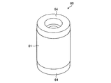
- FIG. 2 is a perspective view of a rotor of the induction motor shown in FIG.
- FIG. 3 is a perspective view of a rotor core of the induction motor shown in FIG.
- FIG. 1 shows a cross section of one side of the induction motor 100 according to the first embodiment.
- the axial direction in which the central axis AX of the rotor core 61 extends is the direction indicated by the arrow D1 in FIG.
- the circumferential direction of the central axis AX of the rotor core 61 is a direction indicated by an arrow D2 in FIG.
- the radial direction of the rotor core 61 is a direction indicated by an arrow D3 in FIG.
- the radial direction of the rotor core 61 is equal to the radial direction of the rotor 60.
- the induction motor 100 is provided on a bottomed cylindrical frame 11, an end plate 12 for closing an opening of the frame 11, an annular stator 10 provided on an inner peripheral surface of the frame 11, and a bottom portion of the frame 11.
- the bearing includes a bearing 1 and a bearing 2 provided on an end plate 12.
- the housing 3 is constituted by the frame 11 and the end plate 12.
- the induction motor 100 also includes a cylindrical rotor 60 provided inside the stator 10 and a shaft 80 rotatably supported by the bearings 1 and 2 and provided inside the rotor 60.
- a rotating magnetic field is generated by an alternating current flowing through the winding of the stator 10, and the rotating magnetic field acts on the secondary conductor of the rotor 60.
- An electromotive force is generated in the secondary conductor, and a current flows.
- the secondary conductor of the rotor 60 is constituted by the conductor bar 63, the end ring 64, and the die cast member 65 shown in FIG.
- An electromagnetic force based on Fleming's left-hand rule is generated between the current flowing through the secondary conductor of the rotor 60 and the rotating magnetic field, whereby the conductor of the rotor 60 is pulled in the direction of the rotating magnetic field, thereby rotating the rotor.
- the child 60 rotates.
- the rotor 60 has a cylindrical rotor core 61 formed by stacking a plurality of steel plates in the axial direction.
- a plurality of slots 62 are formed in the rotor core 61.
- the plurality of slots 62 are arranged apart from each other in the circumferential direction of the rotor core 61.
- the plurality of slots 62 are formed near the outer peripheral surface of the rotor core 61.
- Each of the plurality of slots 62 extends in the axial direction and penetrates from the first end face 61b of the rotor core 61 to the second end face 61c.
- Each of the plurality of slots 62 is skewed in the circumferential direction.
- the rotor 60 includes a conductor bar 63 provided in each of the plurality of slots 62, and an end ring 64 serving as an end ring connecting the plurality of conductor bars 63 provided at both ends in the axial direction of the rotor core 61. And a die-cast member 65 provided in the slot 62.
- the first end face 61b of the rotor core 61 is an end face on one side in the axial direction of the rotor core 61.
- the second end face 61 c of the rotor core 61 is the other end face in the axial direction of the rotor core 61.
- a non-magnetic conductor material such as aluminum, aluminum alloy, copper or copper alloy can be exemplified.
- FIG. 4 is an enlarged view of a portion of the first end face of the rotor core shown in FIG. 3 where a slot is provided.
- a conductor bar 63 is provided in the slot 62, and a projection 61 d 1 and a projection 61 d 2 are provided on a wall surface 61 a forming the slot 62.
- the protrusion 61d1 and the protrusion 61d2 are members for suppressing the movement of the conductor bar 63 in the radial direction.
- FIG. 4 the illustration of the die cast member 65 shown in FIG. 1 is omitted to facilitate understanding of the shapes of the protrusion 61d1, the protrusion 61d2, and the conductor bar 63.
- a die cast member 65 is provided in addition to the protrusion 61d2 and the conductor bar 63.
- the protrusion 61d1 is provided on the first wall surface 61a1 of the wall surface 61a forming the slot 62 when the rotor core 61 is viewed from the first end surface 61b side.
- the first wall surface 61a1 is a surface of the entire wall surface 61a facing the first end surface 63b1 of the conductor bar 63.
- the first end face 63b1 of the conductor bar 63 is one end face of the conductor bar 63 in the circumferential direction.
- the protrusion 61d1 protrudes from the first wall surface 61a1 along the circumferential direction.
- the protrusion 61d2 is provided on the second wall surface 61a2 of the wall surface 61a forming the slot 62 when the rotor core 61 is viewed from the first end surface 61b side.
- the second wall surface 61a2 is a surface facing the second end surface 63b2 of the conductor bar 63 in the entire wall surface 61a.
- the second end face 63b2 of the conductor bar 63 is the other end face in the circumferential direction of the conductor bar 63.
- the protrusion 61d2 protrudes from the second wall surface 61a2 along the circumferential direction.
- a conductor bar 63 is provided radially inward of each of the protrusions 61d1 and 61d2.
- the radially outer surface 63a1 of the conductor bar 63 is in contact with the protrusions 61d1 and 61d2. Further, a corner 63c1 between the radially inner side surface 63a2 of the conductor bar 63 and the first end surface 63b1 of the conductor bar 63 is in contact with the first wall surface 61a1. A corner 63c2 between the radial inner surface 63a2 of the conductor bar 63 and the second end surface 63b2 of the conductor bar 63 is in contact with the second wall surface 61a2.
- the conductor bar 63 is in contact with the protrusions 61d1 and 61d2 on the outside in the radial direction, and is in contact with the first wall surface 61a1 and the second wall surface 61a2 on the inside in the radial direction. Therefore, the movement of the conductor bar 63 in the radial direction is restricted. Therefore, as described later, in the die casting step of filling the gap between the slot 62 and the conductor bar 63 with aluminum, the conductor bar 63 is unlikely to be displaced even if a die casting pressure is applied to the conductor bar 63.
- the gap is, for example, a clearance between the components that are caused by manufacturing tolerances of the components constituting the rotor 60 and variations in the standing of the set of the components. It is desirable that the allowable range of the gap with respect to the radial dimension of the conductor bar 63 be within 5%. For example, when the radial dimension of the conductor bar 63 is 20 mm, the gap is within 1 mm.
- the conductor bar 63 and the protrusion 61d1 are manufactured so that the allowable range of the gap with respect to the radial dimension of the conductor bar 63 is within 5%. Since the operation of inserting the conductor bar 63 into the slot 62 is reduced while the connection is maintained, the assembling operation of the rotor 60 is facilitated, and the rotation of the rotor 60 is suppressed while suppressing the rotation efficiency of the rotor 60 from decreasing. Can improve production efficiency.
- a slight gap may exist between the radially outer surface 63a1 of the conductor bar 63 and the protrusion 61d2, and the allowable range of the gap with respect to the radial dimension of the conductor bar 63 is within 5%. Desirably. Further, a slight gap may exist between the corner 63c1 and the first wall surface 61a1, and the allowable range of the gap with respect to the radial dimension of the conductor bar 63 is desirably 5% or less. Further, a slight gap may exist between the corner 63c2 and the second wall surface 61a2, and the allowable range of the gap with respect to the radial dimension of the conductor bar 63 is desirably 5% or less.
- Each of the protrusions 61d1 and 61d2 may be provided continuously from the first end face 61b to the second end face 61c of the rotor core 61 shown in FIG. 1, or may be provided from the first end face 61b of the rotor core 61 to the first end face 61b.
- a plurality may be provided apart from each other in the axial direction up to the two end surfaces 61c.
- each of the protrusions 61d1 and 61d2 is provided continuously from the first end face 61b to the second end face 61c of the rotor core 61, for example, a plurality of steel plates provided with the protrusions 61d1 and 61d2 are manufactured and manufactured.
- the rotor core 61 may be manufactured by stacking a plurality of steel plates.
- the protrusions 61d1 and the protrusions 61d2 are provided apart from each other in the axial direction, for example, a first steel plate in which two protrusions are formed at a position corresponding to the slot 62, and a first steel plate in which these protrusions are not formed.
- a plurality of two steel plates are manufactured.
- the rotor core 61 may be manufactured by alternately stacking the manufactured first and second steel plates.
- the volume of the die-cast member 65 provided in the slot 62 is smaller than in the case where the projections 61d1 and 61d2 are provided continuously from the first end face 61b to the second end face 61c of the rotor core 61. And the secondary resistance is reduced. Therefore, the rotation efficiency of the rotor 60 can be improved while suppressing the movement of the conductor bar 63 in the radial direction due to the die casting pressure.
- the protrusions 61d1 and the plurality of protrusions 61d2 are provided apart from each other in the axial direction, for example, after stacking a plurality of the above-described first steel plates to manufacture an iron core block, the first end face of the iron core block in the axial direction.
- the rotor core 61 may be manufactured by stacking a plurality of the above-described second steel plates on each of the second end faces.
- the protrusions 61d1 and 61d2 are provided at portions separated from the axial end faces of the rotor core 61 by a certain distance toward the axial center of the rotor core 61.
- the rotor core 61 may be manufactured by stacking a plurality of the first steel plates on each of the two end surfaces.
- the protrusion 61d1 and the protrusion 61d2 are provided on the portion of the rotor core 61 near the first end face 61b in the axial direction and the portion of the rotor core 61 near the second end face 61c in the axial direction. Even when the protrusions 61d1 and 61d2 are provided, the protrusions 61d1 and 61d2 are provided continuously from the first end face 61b in the axial direction of the rotor core 61 toward the second end face 61c.
- the area occupied by the projections 61d1 and 61d2 in the slot 62 is smaller than that of the slot 62. Therefore, the volume of the die cast material filled in the slot 62 is relatively increased. Therefore, the resistance of the die-cast member 65 is reduced, and the rotational efficiency of the rotor 60 can be improved while suppressing the radial movement of the conductor bar 63 due to the die-cast pressure.
- FIG. 5 is a diagram showing a manufacturing process of the rotor shown in FIG.
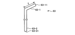
- FIG. 6 is a diagram showing a state in which one end of the conductor bar is bent.
- FIG. 7 is a diagram showing a state where the conductor bar is inserted into the slot of the rotor core.
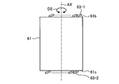
- FIG. 8 is a view showing a state where the second end of the conductor bar is bent.
- FIG. 9 is a diagram showing a state where the end ring and the die cast member are provided.
- step 1 the rotor core 61 and the plurality of conductor bars 63 shown in FIG. 3 are manufactured.
- the rotor core 61 and the plurality of conductor bars 63 may be manufactured at the same time, or one of them may be manufactured first, and then the other may be manufactured.
- step 2 the first ends 63-1 of the plurality of conductor bars 63 are bent as shown in FIG.
- the first end 63-1 of the conductor bar 63 is one end in the axial direction of the conductor bar 63.
- the first end 63-1 is bent at a position separated by a predetermined distance L from the first end face 63-11 of the conductor bar 63 toward the second end face 63-21 of the conductor bar 63.
- the first end face 63-11 of the conductor bar 63 is an end face on one side in the axial direction of the conductor bar 63.
- the second end face 63-21 of the conductor bar 63 is the other end face in the axial direction of the conductor bar 63.
- Constant distance L is set to a value that allows conductor bars 63 adjacent in the circumferential direction to be connected to each other when conductor bars 63 are inserted into slots 62 of rotor core 61.
- each of the plurality of conductor bars 63 whose first end 63-1 is bent is connected to the rotor core 61 from the side of the second end 63-2 which is not bent, as shown in FIG. It is inserted toward the slot 62 opening to the first end face 61b.
- the second end 63-2 is an end of the conductor bar 63 on the other side in the axial direction.
- step 4 the direction in which the first end 63-1 of the conductor bar 63 inserted into each of the plurality of slots 62 extends is adjusted so as to be along the circumferential direction of the rotor core 61.
- the direction in which the first end 63-1 extends is equal to the counterclockwise direction when the rotor core 61 is viewed from the first end face 61b side.
- step 5 the second ends 63-2 of the plurality of conductor bars 63 protruding from the second end face 61c in the axial direction of the rotor core 61 are, as shown in FIG. Are bent so that the direction in which they extend is along the circumferential direction of the rotor core 61.
- the direction in which the second end 63-2 extends is equal to the counterclockwise direction when the rotor core 61 is viewed from the second end face 61c side.
- step 6 the end ring 64 and the die-cast member 65 are die-cast on the rotor core 61 as shown in FIG. 9 by using the above-mentioned non-magnetic conductor material as a die-cast material.
- end rings 64 are provided on each of the first end face 61b and the second end face 61c of the rotor core 61 in the axial direction.
- the end ring 64 has a function of electrically connecting the plurality of conductor bars 63 to each other and a function of fixing each of the plurality of conductor bars 63 to the rotor core 61.
- a die cast member 65 is provided in a gap between the wall 61 a forming the slot 62 and the conductor bar 63 by die casting.
- the die-cast pressure is applied to the conductor bar 63. Even in this case, the displacement of the conductor bars 63 adjacent in the circumferential direction in the axial direction and the radial direction is suppressed. Further, even when a centrifugal force is applied to the conductor bar 63 while the rotor 60 is rotating, the displacement of the conductor bars 63 adjacent in the circumferential direction in the axial direction and the radial direction is suppressed. Therefore, as shown in FIG. 9, in the rotor 60, the state where the adjacent conductor bars 63 are electrically connected can be maintained.
- the secondary resistance on the current path of the rotor 60 that is, the secondary resistance of the conductor bar 63 is smaller than the case where the protrusion 61d1 and the protrusion 61d2 are not provided. Is suppressed, the rotation efficiency of the rotor 60 is improved, and the output of the induction motor 100 is improved.
- the conductor bars 63 are provided radially inward of the protrusions 61 d 1 and 61 d 2, respectively, but the position of the conductor bar 63 is determined in the respective radial directions of the protrusions 61 d 1 and 61 d 2. It may be outside. In this case, the radial outside of the conductor bar 63 contacts the wall surface 61a forming the slot 62, and the radial inside of the conductor bar 63 contacts the protrusion. Even in the case of such a configuration, when the die-cast pressure is applied to the conductor bar 63, the movement of the conductor bar 63 inward in the radial direction is suppressed. The displacement is suppressed.
- the protrusions 61 d 1 and 61 d 2 are provided on the rotor core 61.
- only one of the protrusions 61 d 1 and 61 d 2 may be provided on the rotor core 61.
- the protrusion may be formed only on the first wall surface.
- one projection extending from the radially outer portion to the radially inner side of the wall surface 61a forming the slot 62 may be provided.
- One of the projections extending radially outward from the radially inner portion of the wall surface 61a forming the shape 62 may be provided. Even in the case of such a configuration, it is possible to suppress displacement of the conductor bars 63 adjacent in the circumferential direction in the radial direction.
- the shapes of the protrusions 61d1 and 61d2 are not limited to the shapes shown in FIG. 4, but may be the following shapes.
- FIG. 10 is a configuration diagram of a rotor core according to a modification of the first embodiment of the present invention.
- the rotor core 61A shown in FIG. 10 is provided with a projection 61d11 and a projection 61d21 each having a protruding tip in the circumferential direction instead of the projection 61d1 and the projection 61d2.
- the protrusion 61d11 is formed so as to taper from the first wall surface 61a1 of the wall surface 61a to the second wall surface 61a2.
- the protrusion 61d21 is formed to taper from the second wall surface 61a2 of the wall surface 61a to the first wall surface 61a1.
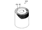
- FIG. FIG. 11 is a perspective view of a rotor core constituting a rotor of an induction motor according to Embodiment 2 of the present invention.
- rotor 60 according to the second embodiment rotor core 61B shown in FIG.
- FIG. 12 is an enlarged view of a portion of the first end face of the rotor core shown in FIG. 11 where a slot is provided.
- the slot 62 of the rotor core 61B is not provided with the projection 61d1 and the projection 61d2 shown in FIG.
- a ring 70 is provided on the radially outer surface 63a1 of the conductor bar 63A inserted into the slot 62 of the rotor core 61B.
- the ring 70 is an annular first restraining member for restraining the conductor bars 63A adjacent in the circumferential direction from being displaced radially outward.
- the inside of the ring 70 is in contact with the radially outer surface 63a1 of the conductor bar 63A. Details of the ring 70 will be described later.
- the second restraining member having the same shape as the ring 70 is fitted into each of the second end portions 63-2 of the plurality of conductor bars 63A protruding from the axial second end surface 61c of the rotor core 61B. That is, for the rotor 60 according to the second embodiment, a suppression member including the first suppression member and the second suppression member is used.
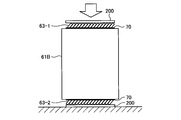
- FIG. 13 is a diagram illustrating a manufacturing process of the rotor according to the second embodiment.
- FIG. 14 is a diagram showing a state where the conductor bar is inserted into the slot of the rotor core in step 12 of FIG.
- FIG. 15 is a view showing a state where the ring is fitted to the conductor bar in step 13 of FIG.
- FIG. 16 is a view showing a state in which both ends of the conductor bar are bent in step 14 of FIG.
- FIG. 17 is a diagram showing a state in which the end ring and the die cast member are provided in step 15 of FIG.
- step 11 When manufacturing the rotor 60 of the second embodiment, first, in step 11, a plurality of rings 70, a rotor core 61B, and a plurality of conductor bars 63A are manufactured.
- each of the plurality of conductor bars 63A is inserted from the second end 63-2 side of the conductor bar 63A into the slot 62 opened in the first end face 61b of the rotor core 61B. Is done.
- step 13 as shown in FIG. 15, the plurality of conductor bars 63A projecting from the axial first end face 61b of the rotor core 61B surround the radially outer faces 63a1 of the respective first end portions 63-1.
- the ring 70 is fitted.
- the ring 70 is similarly fitted into each of the second ends 63-2 of the plurality of conductor bars 63A protruding from the axial second end face 61c of the rotor core 61B.
- the ring 70 may be formed of a metal such as a copper alloy, cast iron, steel, or an iron alloy in a ring shape by die casting, or may be formed in a ring shape using a material having high heat resistance such as meta-aramid fiber or mica. It may be formed of a fiber-reinforced plastic having a relatively low coefficient of thermal expansion while having high rigidity.
- the electrical connection between the conductor bars 63A adjacent in the circumferential direction can be maintained, and therefore, between the radial outer surface 63a1 of the conductor bar 63A and the ring 70. May have a slight gap.
- the gap is, for example, a clearance between the components that are caused by manufacturing tolerances of the components constituting the rotor 60 and variations in the standing of the set of the components.
- step 14 pressure is applied to the first end 63-1 and the second end 63-2 of the conductor bar 63A using a press machine 200 as shown in FIG. 63-1 and the second end 63-2 are bent.
- the slots 62 of the rotor core 61B are skewed in the circumferential direction. Therefore, the first end 63-1 and the second end 63-2 of the conductor bar 63A are obliquely inclined with respect to the axial direction. Therefore, the first end 63-1 and the second end 63-2 of the conductor bar 63A are bent along the circumferential direction when compressed in the axial direction. Thereby, the ends of the adjacent conductor bars 63A come into contact with each other.
- step 15 the end ring 64 and the die cast member 65 are die-cast formed on the rotor core 61B using the above-described non-magnetic conductor material as a die-cast material, as shown in FIG.
- FIG. 18 is a configuration diagram of a ring according to a first modification of the second embodiment of the present invention.
- the ring 70A shown in FIG. 18 may be a member formed of a metal such as a copper alloy, cast iron, steel, an iron alloy or the like into a C-shape by die-casting, or a ring formed of a fiber-reinforced plastic in an annular shape.
- FIG. 19 is a configuration diagram of a ring according to a second modification of the second embodiment of the present invention.
- the ring 70B shown in FIG. 19 is obtained by winding a metal such as a copper alloy, cast iron, steel, or an iron alloy in a coil shape a plurality of times.
- the inner diameter of the ring 70A or the ring 70B can be fitted into the conductor bar 63A while slightly expanding the inner diameter. Even if there is a vertical variation in the set, the assembling work of the rotor 60 is facilitated, and the production efficiency of the rotor 60 is improved.
- a force that pushes the plurality of conductor bars 63A inward in the radial direction acts on the plurality of conductor bars 63A by the restoring force of the ring 70A or the ring 70B, so that the radial direction between the conductor bars 63 adjacent in the circumferential direction is increased.
- the displacement to the outside can be further suppressed.
- the circumferentially adjacent conductor bars 63 are displaced radially outward. Can be suppressed.
- the step of bending the conductor bar 63A before being inserted into the slot 62 becomes unnecessary.
- the time required for the bending step increases as the number of conductor bars 63A used increases, in the second embodiment, the first end 63-1 and the second end 63- 2 can be bent in a short time. Therefore, the production efficiency of the rotor 60 is improved.
- first end 63-1 and second end 63-2 of conductive bar 63A are bent using press machine 200, and are crushed and contacted.
- the area expands. Therefore, the contact area between the adjacent conductor bars 63 can be increased as compared with the case where the press machine 200 is not used. Therefore, the secondary resistance on the current path of the rotor 60 is further reduced, and the rotation efficiency of the rotor 60 is improved.
- the material of the conductor bars 63 and 63A is selected from non-magnetic conductor materials having a lower resistivity than a material having a lower melting point. 60 can be improved in rotational efficiency.
- a material used for die-casting the end ring 64 and the die-cast member 65 a material having a lower melting point than a material having a lower resistivity is preferentially selected from non-magnetic conductor materials, so The production efficiency of the child 60 can be improved. Therefore, for example, by selecting copper as the material of the conductor bars 63 and 63A and selecting aluminum as the material of the end ring 64 and the die-cast member 65, the rotational efficiency and the production efficiency of the rotor 60 can be improved. it can.
- stator 11 frame, 12 end plate, 60 rotor, 61, 61A, 61B rotor core, 61a wall, 61a1 first wall, 61a2 second wall, 61b, 63-11 , 63b1 ⁇ first end face, 61c, 63-21, 63b2 ⁇ second end face, 61d1, 61d11, 61d2, 61d21 ⁇ projection, 62 ⁇ slot, 63, 63A ⁇ conductor bar, 63-1 ⁇ first end, 63-2 ⁇ second end Part, 63a1 radial outer surface, 63a2 ⁇ radial inner surface, 64 ⁇ end ring, 65 die-cast member, 70, 70A, 70B ring, 80 shaft, 100 induction motor, 200 press machine.
Landscapes
- Engineering & Computer Science (AREA)
- Power Engineering (AREA)
- Manufacturing & Machinery (AREA)
- Induction Machinery (AREA)
- Manufacture Of Motors, Generators (AREA)
Abstract
Le rotor pour moteur à induction de l'invention est muni d'un noyau de rotor (61) et d'une barre conductrice (63) disposée dans chacune d'une pluralité de fentes (62) formées dans le noyau de rotor (61), la barre conductrice (63) présentant, d'une part une première section d'extrémité saillant d'une première surface d'extrémité axiale (61b) du noyau de rotor (61), d'autre part une seconde section d'extrémité saillant d'une seconde surface d'extrémité axiale du noyau de rotor (61), la première section d'extrémité et la seconde section d'extrémité étant courbées dans la direction circonférentielle du noyau de rotor (61). Le rotor pour moteur à induction est caractérisé en ce qu'il comprend : une bague d'extrémité disposée sur la première surface d'extrémité (61b) et sur la seconde surface d'extrémité, et raccordant électriquement la pluralité de barres conductrices (63); et des saillies (61d1, 61d2) empêchant un déplacement positionnel radial vers l'extérieur des barres conductrices (63).
Priority Applications (2)
| Application Number | Priority Date | Filing Date | Title |
|---|---|---|---|
| JP2019554430A JPWO2019244205A1 (ja) | 2018-06-18 | 2018-06-18 | 誘導電動機の回転子、誘導電動機及び回転子の製造方法 |
| PCT/JP2018/023106 WO2019244205A1 (fr) | 2018-06-18 | 2018-06-18 | Rotor pour moteur à induction, moteur à induction, et procédé de fabrication du rotor |
Applications Claiming Priority (1)
| Application Number | Priority Date | Filing Date | Title |
|---|---|---|---|
| PCT/JP2018/023106 WO2019244205A1 (fr) | 2018-06-18 | 2018-06-18 | Rotor pour moteur à induction, moteur à induction, et procédé de fabrication du rotor |
Publications (1)
| Publication Number | Publication Date |
|---|---|
| WO2019244205A1 true WO2019244205A1 (fr) | 2019-12-26 |
Family
ID=68982945
Family Applications (1)
| Application Number | Title | Priority Date | Filing Date |
|---|---|---|---|
| PCT/JP2018/023106 Ceased WO2019244205A1 (fr) | 2018-06-18 | 2018-06-18 | Rotor pour moteur à induction, moteur à induction, et procédé de fabrication du rotor |
Country Status (2)
| Country | Link |
|---|---|
| JP (1) | JPWO2019244205A1 (fr) |
| WO (1) | WO2019244205A1 (fr) |
Cited By (1)
| Publication number | Priority date | Publication date | Assignee | Title |
|---|---|---|---|---|
| JP2023064895A (ja) * | 2021-10-27 | 2023-05-12 | 株式会社アイシン | ロータ |
Citations (7)
| Publication number | Priority date | Publication date | Assignee | Title |
|---|---|---|---|---|
| JPH07163107A (ja) * | 1993-12-06 | 1995-06-23 | Mitsubishi Electric Corp | かご形誘導電動機及びこれに駆動される二乗トルク特性を有する流体機械並びにかご形誘導電動機の製造方法 |
| JPH1028360A (ja) * | 1996-07-11 | 1998-01-27 | Hitachi Ltd | 誘導電動機およびその回転子 |
| JPH10174386A (ja) * | 1996-12-04 | 1998-06-26 | Nishishiba Electric Co Ltd | かご形回転子の製造方法 |
| JP2009017697A (ja) * | 2007-07-05 | 2009-01-22 | Toyota Industries Corp | かご型誘導電動機及びかご型誘導電動機の製造方法 |
| JP2009296761A (ja) * | 2008-06-04 | 2009-12-17 | Toshiba Corp | 回転子及びその製造方法 |
| JP2011188703A (ja) * | 2010-03-11 | 2011-09-22 | Mitsubishi Electric Corp | 単相誘導電動機及び密閉型圧縮機 |
| WO2015001601A1 (fr) * | 2013-07-01 | 2015-01-08 | 株式会社日立産機システム | Machine électrique tournante et son procédé de fabrication |
-
2018
- 2018-06-18 WO PCT/JP2018/023106 patent/WO2019244205A1/fr not_active Ceased
- 2018-06-18 JP JP2019554430A patent/JPWO2019244205A1/ja active Pending
Patent Citations (7)
| Publication number | Priority date | Publication date | Assignee | Title |
|---|---|---|---|---|
| JPH07163107A (ja) * | 1993-12-06 | 1995-06-23 | Mitsubishi Electric Corp | かご形誘導電動機及びこれに駆動される二乗トルク特性を有する流体機械並びにかご形誘導電動機の製造方法 |
| JPH1028360A (ja) * | 1996-07-11 | 1998-01-27 | Hitachi Ltd | 誘導電動機およびその回転子 |
| JPH10174386A (ja) * | 1996-12-04 | 1998-06-26 | Nishishiba Electric Co Ltd | かご形回転子の製造方法 |
| JP2009017697A (ja) * | 2007-07-05 | 2009-01-22 | Toyota Industries Corp | かご型誘導電動機及びかご型誘導電動機の製造方法 |
| JP2009296761A (ja) * | 2008-06-04 | 2009-12-17 | Toshiba Corp | 回転子及びその製造方法 |
| JP2011188703A (ja) * | 2010-03-11 | 2011-09-22 | Mitsubishi Electric Corp | 単相誘導電動機及び密閉型圧縮機 |
| WO2015001601A1 (fr) * | 2013-07-01 | 2015-01-08 | 株式会社日立産機システム | Machine électrique tournante et son procédé de fabrication |
Cited By (2)
| Publication number | Priority date | Publication date | Assignee | Title |
|---|---|---|---|---|
| JP2023064895A (ja) * | 2021-10-27 | 2023-05-12 | 株式会社アイシン | ロータ |
| JP7757709B2 (ja) | 2021-10-27 | 2025-10-22 | 株式会社アイシン | ロータ |
Also Published As
| Publication number | Publication date |
|---|---|
| JPWO2019244205A1 (ja) | 2020-06-25 |
Similar Documents
| Publication | Publication Date | Title |
|---|---|---|
| JP5774255B1 (ja) | かご型回転子の製造方法およびかご型回転子 | |
| US11088601B2 (en) | Method for producing armature, method for producing dynamo-electric machine, armature, dynamo-electric machine, and device for producing armature | |
| JP5955451B2 (ja) | 埋込磁石型回転子、埋込磁石型回転電機、及び埋込磁石型回転子の製造方法 | |
| JPWO2020017133A1 (ja) | 分布巻ラジアルギャップ型回転電機及びその固定子 | |
| US10658888B2 (en) | Rotary electric machine including an inner core formed of steel sheets with connected and non-connected tooth portions and manufacturing method therefor | |
| CN108370178A (zh) | 轴向间隙型旋转电机及其制造方法 | |
| US20180351417A1 (en) | Rotating electric machine stator, rotating electric machine, and method for manufacturing rotating electric machine stator | |
| US8674580B2 (en) | Electric machine with end ring and supporting tab | |
| JP2018068090A (ja) | 同期リラクタンス型回転電機 | |
| US20180145549A1 (en) | Rotary electric machine and manufacturing method for rotary electric machine | |
| JPWO2019087358A1 (ja) | 回転電機の電機子鉄心、及び回転電機の電機子鉄心の製造方法 | |
| JP6338767B2 (ja) | 回転電機 | |
| JP2011182600A (ja) | 回転電動機 | |
| JPWO2019176107A1 (ja) | 誘導電動機の回転子及び誘導電動機 | |
| JPWO2019123977A1 (ja) | 固定子の製造方法 | |
| JP6113049B2 (ja) | 回転電機のステータ | |
| WO2019244205A1 (fr) | Rotor pour moteur à induction, moteur à induction, et procédé de fabrication du rotor | |
| JP2016116421A (ja) | 回転電機 | |
| JP6279122B1 (ja) | 回転電機 | |
| JP2010200573A (ja) | 永久磁石形同期電動機 | |
| CN107980197A (zh) | 感应电动机的转子及感应电动机 | |
| JP6538244B2 (ja) | かご型回転電機 | |
| JP2017046369A (ja) | 電機子、電機子の製造方法および回転電機 | |
| JP6739638B2 (ja) | 回転電機の回転子及び回転電機 | |
| JP7229402B2 (ja) | 電機子の製造方法、及び、電機子 |
Legal Events
| Date | Code | Title | Description |
|---|---|---|---|
| ENP | Entry into the national phase |
Ref document number: 2019554430 Country of ref document: JP Kind code of ref document: A |
|
| 121 | Ep: the epo has been informed by wipo that ep was designated in this application |
Ref document number: 18923283 Country of ref document: EP Kind code of ref document: A1 |
|
| NENP | Non-entry into the national phase |
Ref country code: DE |
|
| 122 | Ep: pct application non-entry in european phase |
Ref document number: 18923283 Country of ref document: EP Kind code of ref document: A1 |