WO2019244281A1 - Électrode positive de batterie secondaire à électrolyte non aqueux et batterie secondaire à électrolyte non aqueux - Google Patents
Électrode positive de batterie secondaire à électrolyte non aqueux et batterie secondaire à électrolyte non aqueux Download PDFInfo
- Publication number
- WO2019244281A1 WO2019244281A1 PCT/JP2018/023467 JP2018023467W WO2019244281A1 WO 2019244281 A1 WO2019244281 A1 WO 2019244281A1 JP 2018023467 W JP2018023467 W JP 2018023467W WO 2019244281 A1 WO2019244281 A1 WO 2019244281A1
- Authority
- WO
- WIPO (PCT)
- Prior art keywords
- electron microscope
- microscope image
- positive electrode
- granular
- ratio
- Prior art date
- Legal status (The legal status is an assumption and is not a legal conclusion. Google has not performed a legal analysis and makes no representation as to the accuracy of the status listed.)
- Ceased
Links
Images








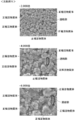
Classifications
-
- H—ELECTRICITY
- H01—ELECTRIC ELEMENTS
- H01M—PROCESSES OR MEANS, e.g. BATTERIES, FOR THE DIRECT CONVERSION OF CHEMICAL ENERGY INTO ELECTRICAL ENERGY
- H01M10/00—Secondary cells; Manufacture thereof
- H01M10/05—Accumulators with non-aqueous electrolyte
- H01M10/052—Li-accumulators
-
- H—ELECTRICITY
- H01—ELECTRIC ELEMENTS
- H01M—PROCESSES OR MEANS, e.g. BATTERIES, FOR THE DIRECT CONVERSION OF CHEMICAL ENERGY INTO ELECTRICAL ENERGY
- H01M10/00—Secondary cells; Manufacture thereof
- H01M10/05—Accumulators with non-aqueous electrolyte
- H01M10/056—Accumulators with non-aqueous electrolyte characterised by the materials used as electrolytes, e.g. mixed inorganic/organic electrolytes
- H01M10/0564—Accumulators with non-aqueous electrolyte characterised by the materials used as electrolytes, e.g. mixed inorganic/organic electrolytes the electrolyte being constituted of organic materials only
- H01M10/0566—Liquid materials
-
- H—ELECTRICITY
- H01—ELECTRIC ELEMENTS
- H01M—PROCESSES OR MEANS, e.g. BATTERIES, FOR THE DIRECT CONVERSION OF CHEMICAL ENERGY INTO ELECTRICAL ENERGY
- H01M4/00—Electrodes
- H01M4/02—Electrodes composed of, or comprising, active material
- H01M4/13—Electrodes for accumulators with non-aqueous electrolyte, e.g. for lithium-accumulators; Processes of manufacture thereof
- H01M4/131—Electrodes based on mixed oxides or hydroxides, or on mixtures of oxides or hydroxides, e.g. LiCoOx
-
- Y—GENERAL TAGGING OF NEW TECHNOLOGICAL DEVELOPMENTS; GENERAL TAGGING OF CROSS-SECTIONAL TECHNOLOGIES SPANNING OVER SEVERAL SECTIONS OF THE IPC; TECHNICAL SUBJECTS COVERED BY FORMER USPC CROSS-REFERENCE ART COLLECTIONS [XRACs] AND DIGESTS
- Y02—TECHNOLOGIES OR APPLICATIONS FOR MITIGATION OR ADAPTATION AGAINST CLIMATE CHANGE
- Y02E—REDUCTION OF GREENHOUSE GAS [GHG] EMISSIONS, RELATED TO ENERGY GENERATION, TRANSMISSION OR DISTRIBUTION
- Y02E60/00—Enabling technologies; Technologies with a potential or indirect contribution to GHG emissions mitigation
- Y02E60/10—Energy storage using batteries
Definitions
- the present invention relates to a positive electrode for a non-aqueous electrolyte secondary battery and a non-aqueous electrolyte secondary battery using a positive electrode active material containing lithium and nickel.
- a positive electrode active material containing lithium (Li) is used for the positive electrode of the existing non-aqueous electrolyte secondary battery.
- a positive electrode active material containing lithium and nickel (Ni) has attracted attention (for example, see Patent Document 1).
- the positive electrode active material containing nickel By using the positive electrode active material containing nickel, the charge / discharge capacity of the nonaqueous electrolyte secondary battery is increased.
- the non-aqueous electrolyte secondary battery using a positive electrode active material containing lithium and nickel should have higher battery characteristics and higher durability.
- the battery characteristics are, for example, charge and discharge efficiency.
- the present invention improves the battery characteristics and improves the durability of the battery as compared with a conventional positive electrode for a non-aqueous electrolyte secondary battery using a positive electrode active material containing lithium and nickel. It is an object to provide a positive electrode for a non-aqueous electrolyte secondary battery using a positive electrode active material containing the same.
- the positive electrode for a non-aqueous electrolyte secondary battery in Patent Document 1 uses an organic solvent-based binder.
- a positive electrode for a non-aqueous electrolyte secondary battery using a positive electrode active material containing lithium and nickel those using a water-dispersible or water-soluble binder have also been developed, but those containing nickel at a high concentration are not It has not been put to practical use.
- the present inventors have studied a conventional positive electrode for a non-aqueous electrolyte secondary battery including a positive electrode active material containing lithium and nickel.
- the positive electrode active material members are connected to each other by a connecting portion including a conductive material.
- the positive electrode active material body is an aggregate of primary particles of the positive electrode active material.
- the conductive material contained in the connection portion here is a conductive material having a diameter of 1 ⁇ m or less.
- the conductive material in the following description also means a conductive material having a diameter of 1 ⁇ m or less.
- the connection part of the conventional positive electrode includes a conductive material and a binder.
- the connecting portion of the conventional positive electrode is substantially composed of only a conductive material.
- the entire surface of the connecting portion has a granular feeling.
- the inventors of the present application have made a positive electrode for a non-aqueous electrolyte secondary battery using a water-soluble or water-dispersible binder by changing the material and the procedure.
- the positive electrode for a non-aqueous electrolyte secondary battery in which the connection portion has both a granular portion and a non-granular portion is produced. I was able to.
- the portion of the surface of the connecting portion that does not have a granular feeling is made of a substance other than the conductive material that covers the conductive material. That is, the conductive material is covered with a substance other than the conductive material on a part of the surface of the connecting portion.
- the surface of the connection portion should have a granular feeling of the conductive material in order to improve the charge / discharge efficiency of the nonaqueous electrolyte secondary battery.
- the inventors of the present application have noticed that the presence of both a grainy portion and a grainless portion of the conductive material on the surface of the connecting portion can enhance the battery characteristics as compared with the conventional positive electrode.
- the inventors have noticed that the existence of a portion having no graininess on the surface of the connection portion can enhance the durability of the battery as compared with the conventional positive electrode.
- the electrolyte does not easily permeate the connecting portion.
- a portion having a granular feeling on the surface of the connecting portion is apt to penetrate the electrolytic solution. Therefore, it has been found that even if there is a portion having no graininess on the surface of the connecting portion, the degree of freedom of movement of lithium ions can be secured to the same degree as that of the conventional positive electrode.
- the conductive material is covered with a substance other than the conductive material on a part of the surface of the connection portion, even if the positive electrode active material body expands or contracts at the time of charging and discharging the battery, the conductive material at the connection portion It was found that the connection between them was harder to break than the conventional positive electrode. Thereby, the conductivity of the electrons by the connection part is improved, and the electrode resistance of the battery is reduced. As a result, the charging and discharging efficiency is improved as compared with the conventional non-aqueous electrolyte secondary battery.
- the conductive material is covered with a substance other than the conductive material on a part of the surface of the connecting part, the conductive material is also provided on a part of the surface layer in contact with the positive electrode active material body of the connecting part. It can be estimated that it is covered with a substance other than the conductive material. This makes it difficult for the electrolytic solution to come into contact with the surface of the positive electrode active material body through the connecting portion. That is, it is possible to prevent the electrolyte from coming into contact with the positive electrode active material through the connection while ensuring the ease of infiltration of the electrolyte into the connection.
- the electrolyte does not easily come into contact with the positive electrode active material body, the electrolyte does not easily undergo electrolysis even when the battery is used at a high voltage. Therefore, even when used at a higher voltage, deterioration of the battery due to electrolysis of the electrolyte can be suppressed as compared with a conventional nonaqueous electrolyte secondary battery.
- the positive electrode for a non-aqueous electrolyte secondary battery of the present invention includes a positive electrode active material body in which positive electrode active material particles containing lithium and nickel are aggregated, and a conductive material having a diameter of 1 ⁇ m or less.
- the surface of the connection portion has a granular feeling of the conductive material, respectively.
- a grainy surface portion and a non-granularity surface portion having less graininess than the grainy surface portion are confirmed.
- a granular surface and a non-particle surface are confirmed on the surface of the connecting portion.
- the grainy surface has a graininess of the conductive material.
- the non-granular surface has less granularity than the granular surface.
- the non-granular surface is made of a substance other than the conductive material that covers the conductive material. That is, the conductive material is covered with a substance other than the conductive material on a part of the surface of the connecting portion. On the other hand, the conductive material is exposed in almost all areas of the granular feeling surface portion.
- the electrolyte does not easily permeate the connecting portion.
- the connecting portion has not only a portion having no graininess but also a portion having a graininess.
- the electrolytic solution easily penetrates into the granular part. For this reason, even if there is a portion having no graininess on the surface of the connecting portion, the degree of freedom of movement of lithium ions can be secured to the same degree as the conventional positive electrode.
- the conductive material is covered with a substance other than the conductive material on a part of the surface of the connection portion, even if the positive electrode active material body expands or contracts during charging and discharging of the battery, the conductive material in the connection portion The connection between them is less likely to break than the conventional positive electrode. Thereby, the conductivity of the electrons by the connection part is improved, and the electrode resistance of the battery is reduced. As a result, the charging and discharging efficiency is improved as compared with the conventional non-aqueous electrolyte secondary battery.
- the conductive material is covered with a substance other than the conductive material on a part of the surface of the connection part, a part of the positive electrode active material body is fixed by the connection part. Therefore, even if the positive electrode active material body expands or contracts during charging and discharging of the battery, cracks in the positive electrode active material body are less likely to occur than in the conventional positive electrode. Therefore, since the occurrence of cracks in the positive electrode active material body is suppressed, a decrease in charge / discharge efficiency due to the use of the battery is suppressed. Further, as compared with the conventional nonaqueous electrolyte secondary battery, the deterioration of the positive electrode due to the occurrence of cracks in the positive electrode active material body can be suppressed.
- the conductive material is covered with a substance other than the conductive material on a part of the surface of the connecting part, the conductive material is also provided on a part of the surface layer in contact with the positive electrode active material body of the connecting part. It can be estimated that it is covered with a substance other than the conductive material. This makes it difficult for the electrolytic solution to come into contact with the surface of the positive electrode active material body through the connecting portion. That is, it is possible to prevent the electrolyte from coming into contact with the positive electrode active material through the connection while ensuring the ease of infiltration of the electrolyte into the connection.
- the electrolyte does not easily come into contact with the positive electrode active material body, the electrolyte does not easily undergo electrolysis even when the battery is used at a high voltage. Therefore, even when used at a higher voltage, deterioration of the battery due to electrolysis of the electrolyte can be suppressed as compared with a conventional nonaqueous electrolyte secondary battery.
- the connecting portion has a granular feeling surface part with a granular feeling and a non-granular feeling surface part without a granular feeling, so that the positive electrode active material body containing lithium and nickel was used.
- the durability of the battery can be improved while improving the battery characteristics.
- the positive electrode for a non-aqueous electrolyte secondary battery of the present invention preferably has the following configuration in addition to the configuration of (1).
- the area of the granular surface area and the area of the non-granular surface area in each of the at least one electron microscope image are each a square of half the average diameter of the conductive material having a diameter of 1 ⁇ m or less. Is multiplied by 10 or more times the value obtained by multiplying by the pi.
- the area of the granular surface and the area of the non-granular surface in the electron microscope image are large to some extent. Therefore, the effect obtained by having the granular feeling surface part and the non-granular feeling surface part can be obtained more reliably.
- the positive electrode for a nonaqueous electrolyte secondary battery of the present invention preferably has the following configuration in addition to the configuration of (1) or (2).
- a first electron microscope image included in the at least one electron microscope image when performing a binarization process that distinguishes the electron microscope image into a dark region indicating a concave portion and a bright region indicating a convex portion, The ratio of the area of the dark region occupying at least a part of the non-granular surface part in the first electron microscope image is the dark area occupying at least a part of the granular surface part in the first electron microscope image. It is smaller than the ratio of the area of the region.
- the ratio of the area of the dark region occupying at least a part of the non-granularity surface portion is determined by the ratio of the area of the dark region occupying at least a part of the granular feeling surface portion. It tends to be smaller than the area ratio.
- the positive electrode for a non-aqueous electrolyte secondary battery of the present invention preferably has the following configuration in addition to the above configuration (1) or (2).
- the connection unit The grainy surface portion and the non-granularity surface portion were confirmed on the surface of the surface, and the electron microscope image was darkened to indicate a concave portion with respect to the second electron microscope image and the third electron microscope image, respectively.
- the ratio of the area of the dark region occupying at least a part of the non-granular surface in the second electron microscope image is smaller.
- the area without graininess has a small ratio of the dark area by the binarization processing. Therefore, the ratio of the area of the dark region occupying at least a part of the non-granular feeling surface part in one electron microscopic image (second electron microscopic image) is determined by the granularity in another electron microscopic image (third electron microscopic image). It tends to be smaller than the ratio of the area of the dark region to at least a part of the surface portion.
- the granularity of the non-granular surface and the granular surface which are visually separated from the positive electrode surface, are visually determined. The degree can be compared by numerical values such as a ratio of a dark region on the non-granular surface and a ratio of a dark region on the granular surface.
- the positive electrode for a non-aqueous electrolyte secondary battery of the present invention preferably has the following configuration in addition to the configuration of (3) or (4).
- the area of at least a part of the non-granular feel surface portion in the first electron microscope image is obtained by multiplying a square of a half of an average diameter of the conductive material having a diameter of 1 ⁇ m or less by a pi. 10 times or more of the value obtained by the above, and the area of at least a part of the granular feeling surface portion in the first electron microscope image is ⁇ of the average diameter of the conductive material having a diameter of 1 ⁇ m or less. It is at least 10 times the value obtained by multiplying the squared value by the pi.
- the area of at least a part of the non-granular feel surface portion in the second electron microscope image is obtained by multiplying a square of a half of an average diameter of the conductive material having a diameter of 1 ⁇ m or less by a pi. 10 times or more of the value obtained by the above, and the area of at least a part of the granular feeling surface portion in the third electron microscope image is ⁇ of the average diameter of the conductive material having a diameter of 1 ⁇ m or less. It is at least 10 times the value obtained by multiplying the squared value by the pi.
- the area for which the ratio of the area of the dark area is obtained by the binarization processing is somewhat large.
- the region for which the ratio of the area of the dark region is obtained by the binarization process is large to some extent. Therefore, the degree of the granularity visually determined between the non-granularity surface portion and the granularity surface portion can be reliably quantified by the ratio of the area of the dark region. Therefore, it is possible to surely obtain an effect that the degree of granularity of a part having no granularity and a part having no granularity can be compared by numerical values.
- the positive electrode for a nonaqueous electrolyte secondary battery of the present invention may have the following configuration in addition to any one of the above (3) to (5). preferable.
- the ratio of the area of the dark region occupying at least a part of the non-granular feel surface portion in a fourth electron microscope image that is one of the first electron microscope image or the second electron microscope image is the second electron microscope image. 4.
- Electron microscope images (fourth electron microscope image and fifth electron microscope image) of the surface of the positive electrode include a gap between the positive electrode active material bodies, a gap between the positive electrode active material body and the connection portion, and one of the connection portions. There is a gap between the part and the other part of the connecting part. Such a gap in the electron microscope image is included in the dark area by the binarization processing. The ratio of the area of the dark region to the entire electron microscope image is somewhat larger than zero. In a certain electron microscope image (fourth electron microscope image), the ratio of the area of the dark region occupying at least a part of the non-granular feeling surface part is determined by the electron microscope image (fourth electron microscope image) or the electron microscope image.
- the ratio of the area of the dark region to at least a part of the non-granular surface is not too large. This makes it difficult for the connection between the conductive materials to be disconnected at the connection portion, so that the charge / discharge efficiency can be increased. Furthermore, since cracks are less likely to occur in the positive electrode active material body, deterioration of the positive electrode can be suppressed. In addition, since the electrolyte is less likely to be electrolyzed, deterioration of the battery can be suppressed.
- the positive electrode for a nonaqueous electrolyte secondary battery of the present invention may have the following configuration in addition to any of the above configurations (3) to (6). preferable.
- the sixth electron microscope image which is one of the first electron microscope image or the third electron microscope image
- the ratio of the area of the dark region occupying at least a part of the granular surface portion is the sixth electron microscope image.
- the ratio of the area of the dark region to the entire electron microscope image of the above, and the type and acceleration voltage of the sixth electron microscope image and the electron image are the same, and the object to be photographed is different for the nonaqueous electrolyte secondary battery.
- a seventh electron microscope image in which the surface of the positive electrode is not photographed with the binder is obtained, and the binarization process is performed to obtain a ratio of the area ratio of the dark region to the entire seventh electron microscope image. It is at least one or more.
- the electron microscope images (the sixth electron microscope image and the seventh electron microscope image) of the surface of the positive electrode include a gap between the positive electrode active material bodies, a gap between the positive electrode active material body and the connecting portion, and a portion of the connecting portion. There is a gap between the part and the other part of the connecting part.
- Such a gap in the electron microscope image is included in the dark area by the binarization processing. Therefore, the ratio of the area of the dark region shown in the entire electron microscope image is larger than zero, but does not become extremely large.
- the ratio of the area of the dark region occupying at least a part of the grainy surface part in a certain electron microscope image (sixth electron microscope image) is different from the electron microscope image (sixth electron microscope image) or the electron microscope image.
- the ratio of the area of the dark region to the entire seventh electron microscope image is not less than the ratio of the area of the dark region to the entire seventh electron microscope image. Therefore, the ratio of the area of the dark region occupying at least a part of the granular feeling surface portion is not too small. This makes it easier for the electrolyte to penetrate into the connecting portion, so that freedom of movement of lithium ions in the connecting portion can be secured. Therefore, the improvement of the charge / discharge efficiency of the battery due to the non-granular feeling surface portion is not prevented.
- the positive electrode for a nonaqueous electrolyte secondary battery of the present invention may have the following configuration in addition to any one of the above (3) to (7). preferable.
- a ratio of an area of the dark region occupying the at least a part of the non-granular surface portion is less than 10%.
- the ratio of the area of the dark region occupying at least a part of the non-granular feeling surface portion is not too large. This makes it difficult for the connection between the conductive materials to be disconnected at the connection portion, so that the charge / discharge efficiency can be increased. Furthermore, since cracks are less likely to occur in the positive electrode active material body, deterioration of the positive electrode can be suppressed. In addition, since the electrolyte is less likely to be electrolyzed, deterioration of the battery can be suppressed.
- the positive electrode for a nonaqueous electrolyte secondary battery of the present invention may have the following configuration in addition to any one of the above (3) to (8). preferable.
- the ratio of the area of the dark region occupying at least a part of the grainy surface in at least one of the first electron microscope image and the third electron microscope image is 10% or more.
- the ratio of the area of the dark region occupying at least a part of the granular feeling surface portion is not too small. This makes it easier for the electrolyte to penetrate into the connecting portion, so that freedom of movement of lithium ions in the connecting portion can be secured. Therefore, the improvement of the charge / discharge efficiency of the battery due to the non-granular feeling surface portion is not prevented.
- the positive electrode for a nonaqueous electrolyte secondary battery of the present invention may have the following configuration in addition to any one of the above (1) to (9). preferable.
- the conductive material is exposed on the granular surface.
- the positive electrode for a nonaqueous electrolyte secondary battery of the present invention may have the following configuration in addition to any one of the above (1) to (10). preferable.
- the conductive material is not exposed on the non-granular surface.
- the positive electrode for a non-aqueous electrolyte secondary battery of the present invention may have the following configuration in addition to any of the above configurations (1) to (11). preferable.
- the surface of the connection portion includes the granular surface and the non-aqueous surface. A grainy surface is observed.
- the connecting portion has a non-granular surface and a granular surface. Therefore, the non-granular surface part and the granular surface part of the connecting part are not accidentally formed by the way of photographing the electron microscope image.
- the positive electrode for a non-aqueous electrolyte secondary battery of the present invention may have the following configuration in addition to any one of the above (1) to (12). preferable.
- the ratio of nickel to the metal element contained in the positive electrode active material particles is 50 mol% or more.
- the charge / discharge capacity of the nonaqueous electrolyte secondary battery using the positive electrode for a nonaqueous electrolyte secondary battery can be further increased.
- the positive electrode for a non-aqueous electrolyte secondary battery of the present invention may have the following configuration in addition to any one of the above (1) to (13). preferable.
- the ratio of nickel to the metal element contained in the positive electrode active material particles is 80 mol% or more.
- the charge / discharge capacity of the non-aqueous electrolyte secondary battery using the positive electrode for a non-aqueous electrolyte secondary battery can be further increased.
- the non-aqueous electrolyte secondary battery of the present invention includes the positive electrode for a non-aqueous electrolyte secondary battery according to any one of the above (1) to (14), a negative electrode, and a non-aqueous electrolyte. It is characterized by.
- the positive electrode for a nonaqueous electrolyte secondary battery of the present invention preferably has the following configuration in addition to the configuration of (3).
- the ratio of the area of the dark region occupying at least a part of the non-granular surface part in the first electron microscope image occupies at least a part of the granular surface part in the first electron microscope image. It is preferable that the ratio is not more than half of the area ratio of the dark region.
- the ratio of the area of the dark region to at least a part of the non-granular surface in the first electron microscope image is not too large. This makes it difficult for the connection between the conductive materials to be disconnected at the connection portion, so that the charge / discharge efficiency can be increased. Furthermore, since cracks are less likely to occur in the positive electrode active material body, deterioration of the positive electrode can be suppressed. In addition, since the electrolyte is less likely to be electrolyzed, deterioration of the battery can be suppressed.
- the ratio of the area of the dark region occupying at least a part of the non-granular surface is not more than half the ratio of the area of the dark region occupying at least a part of the granular surface.
- the ratio of the area of the dark region occupying at least a portion of the grainy surface portion is the ratio of the area ratio of the dark region occupying at least a portion of the non-granularity surface portion. It is more than twice. Therefore, the ratio of the area of the dark region occupying at least a part of the grainy surface portion is not too small. This makes it easier for the electrolyte to penetrate into the connecting portion, so that freedom of movement of lithium ions in the connecting portion can be secured. Therefore, the improvement of the charge / discharge efficiency of the battery due to the non-granular feeling surface portion is not prevented.
- the positive electrode for a nonaqueous electrolyte secondary battery of the present invention preferably has the following configuration in addition to the configuration of the above (4).
- the ratio of the area of the dark region occupying at least a part of the non-granular surface part in the second electron microscope image occupies at least a part of the granular surface part in the third electron microscope image. It is preferable that the ratio is not more than half of the area ratio of the dark region.
- the ratio of the area of the dark region to at least a part of the non-granular surface in the second electron microscope image is not too large. This makes it difficult for the connection between the conductive materials to be disconnected at the connection portion, so that the charge / discharge efficiency can be increased. Furthermore, since cracks are less likely to occur in the positive electrode active material body, deterioration of the positive electrode can be suppressed. In addition, since the electrolyte is less likely to be electrolyzed, deterioration of the battery can be suppressed.
- the ratio of the area of the dark region occupying at least a part of the non-granular surface part in the second electron microscope image is equal to the ratio of the dark area occupying at least a part of the granular surface part in the third electron microscopic image.
- the ratio of the area of the dark region occupying at least a part of the granular feeling surface portion in the third electron microscope image is less than half of the area ratio. It is at least twice the ratio of the area of the dark region occupying at least a part of the sensitive surface portion. Therefore, the ratio of the area of the dark region occupying at least a part of the grainy surface portion is not too small. This makes it easier for the electrolyte to penetrate into the connecting portion, so that freedom of movement of lithium ions in the connecting portion can be secured. Therefore, the improvement of the charge / discharge efficiency of the battery due to the non-granular feeling surface portion is not prevented.
- the positive electrode for a nonaqueous electrolyte secondary battery of the present invention preferably has the following configuration in addition to any of the above configurations (1) to (17). .
- the granular surface portion in each of the at least one electron microscope image includes a region including 10 or more conductive materials having a diameter of 1 ⁇ m or less, and the non-particle surface portion in each of the at least one electron microscope image.
- the area is equal to or larger than the area of the region including 10 or more conductive materials having a diameter of 1 ⁇ m or less in the granular surface portion.
- the area of the granular surface and the area of the non-granular surface in the electron microscope image are large to some extent. Therefore, the effect obtained by having the granular feeling surface part and the non-granular feeling surface part can be obtained more reliably.
- the positive electrode for a nonaqueous electrolyte secondary battery of the present invention preferably has the following configuration in addition to any of the above configurations (1) to (18). .
- the granular surface portion in each of the at least one electron microscope image includes a region including 10 or more conductive materials having a diameter of 1 ⁇ m or less, and the non-particle surface portion in each of the at least one electron microscope image includes And a region including 10 or more conductive materials having a diameter of 1 ⁇ m or less.
- the area of the granular surface and the area of the non-granular surface in the electron microscope image are large to some extent. Therefore, the effect obtained by having the granular feeling surface part and the non-granular feeling surface part can be obtained more reliably.
- the positive electrode for a nonaqueous electrolyte secondary battery of the present invention preferably has the following configuration in addition to the configuration of (3).
- the at least a portion of the grainy surface portion in the first electron microscope image includes a region including 10 or more conductive materials having a diameter of 1 ⁇ m or less, and the non-granularity surface portion in the first electron microscope image. At least a part of the area is equal to or larger than the area of the region including 10 or more conductive materials having a diameter of 1 ⁇ m or less in the granular surface portion.
- the area where the ratio of the area of the dark area is obtained by the binarization process is large to some extent in the grainy surface in the electron microscope image. Further, in the non-granular feeling surface portion in the electron microscope image, the area for which the ratio of the area of the dark area is obtained by the binarization processing is somewhat large. Therefore, the degree of the granularity visually determined for the granular surface and the non-granular surface can be reliably quantified by the ratio of the area of the dark region. Therefore, it is possible to surely obtain an effect that the degree of granularity of a part having no granularity and a part having no granularity can be compared by numerical values.
- the positive electrode for a non-aqueous electrolyte secondary battery of the present invention preferably has the following configuration in addition to the configuration of (3).
- the at least a part of the grainy surface portion in the first electron microscope image is a region including 10 or more conductive materials having a diameter of 1 ⁇ m or less, and the non-granularity surface portion in the first electron microscope image. Is at least a region including at least 10 conductive materials having a diameter of 1 ⁇ m or less.
- the area where the ratio of the area of the dark area is obtained by the binarization process is large to some extent in the grainy surface in the electron microscope image. Further, in the non-granular feeling surface portion in the electron microscope image, the area for which the ratio of the area of the dark area is obtained by the binarization processing is somewhat large. Therefore, the degree of the granularity visually determined for the granular surface and the non-granular surface can be reliably quantified by the ratio of the area of the dark region. Therefore, it is possible to surely obtain an effect that the degree of granularity of a part having no granularity and a part having no granularity can be compared by numerical values.
- the positive electrode for a non-aqueous electrolyte secondary battery of the present invention preferably has the following configuration in addition to the configuration of the above (4).
- the at least a part of the grainy surface portion in the third electron microscope image includes a region including 10 or more conductive materials having a diameter of 1 ⁇ m or less, and the non-granularity surface portion in the second electron microscope image.
- At least a part of the area is a region in the granular feeling surface portion that includes 10 or more conductive materials having a diameter of 1 ⁇ m or less.
- the area for which the ratio of the area of the dark area is obtained by the binarization processing is somewhat large.
- the region for which the ratio of the area of the dark region is obtained by the binarization process is large to some extent. Therefore, the degree of the granularity visually determined between the non-granularity surface portion and the granularity surface portion can be reliably quantified by the ratio of the area of the dark region. Therefore, it is possible to surely obtain an effect that the degree of granularity of a part having no granularity and a part having no granularity can be compared by numerical values.
- the positive electrode for a nonaqueous electrolyte secondary battery of the present invention preferably has the following configuration in addition to the configuration of the above (4).
- the at least a part of the grainy surface portion in the third electron microscope image includes a region including 10 or more conductive materials having a diameter of 1 ⁇ m or less, and the non-granularity surface portion in the second electron microscope image. At least a portion includes 10 or more conductive materials having a diameter of 1 ⁇ m or less.
- the area for which the ratio of the area of the dark area is obtained by the binarization processing is somewhat large.
- the region for which the ratio of the area of the dark region is obtained by the binarization process is large to some extent. Therefore, the degree of the granularity visually determined between the non-granularity surface portion and the granularity surface portion can be reliably quantified by the ratio of the area of the dark region. Therefore, the effect of numerically comparing the degree of granularity of a part without granularity and a part without granularity is reliably obtained.
- the positive electrode for a nonaqueous electrolyte secondary battery of the present invention may have the following configuration in addition to any one of the above (1) to (23). preferable.
- the at least one electron microscope image is an image captured at a magnification of 2,000 to 8,000 times.
- the positive electrode for a nonaqueous electrolyte secondary battery of the present invention preferably has the following configuration in addition to any of the above configurations (1) to (24). .
- the positive electrode has a sheet shape.
- the positive electrode has a connection strength such that the positive electrode active material body and the connecting portion are not separated from the current collector. The active material body and the connection portion are connected to the current collector.
- the positive electrode for a nonaqueous electrolyte secondary battery of the present invention preferably has the following configuration in addition to any of the above configurations (1) to (25). .
- a discharge capacity of 0.1 C per weight of the positive electrode active material particles at 25 ⁇ 2 ° C. of the half cell It is 90% or more of the maximum discharge capacity depending on the material, the diameter of the positive electrode active material particles, and the diameter of the positive electrode active material body.
- the 0.1 C discharge capacity of a half cell manufactured using the positive electrode for a non-aqueous electrolyte secondary battery is a level that can sufficiently withstand practical use.
- positive electrode active material particles are primary particles of a positive electrode active material.
- the “positive electrode active material body” is a secondary particle formed by aggregating primary particles of a positive electrode active material.
- the “conductive material having a diameter of 1 ⁇ m or less” is a conductive material having a diameter of 1 ⁇ m or less.
- the diameter of the conductive material may be the diameter of the conductive material shown in the electron microscope image of the surface of the positive electrode for a non-aqueous electrolyte secondary battery, or the conductive material shown in the electron microscopic image of the cross section of the positive electrode for a non-aqueous electrolyte secondary battery.
- the particle size of the material may be used.
- the diameter of the conductive material may be measured by using an electron microscope image showing the conductive material.
- the diameter of the conductive material may be measured by a method other than the method using an electron microscope image.
- the two-dimensional shape of the conductive material may be circular or non-circular.
- the conductive material shown in the electron microscope image of the surface and / or cross section of the positive electrode for a non-aqueous electrolyte secondary battery may be circular or non-circular.
- the three-dimensional shape of the conductive material may be spherical or non-spherical.
- the diameter of the sphere corresponding to the same volume as the conductive material may be used as the diameter of the conductive material.
- the maximum length of the outer shape on a certain surface of the conductive material may be used.
- the “conductive material having a diameter of 1 ⁇ m or less” may be a conductive material having a thickness of more than 1 ⁇ m.
- a conductive material having a thickness of 1 ⁇ m or less may be used.
- Having a thickness in a direction perpendicular to the radial direction of the conductive material may mean, for example, having a thickness in a direction perpendicular to the radial direction of the conductive material.
- the “conductive material having a diameter of 1 ⁇ m or less” is a conductive material having a longitudinal length exceeding 1 ⁇ m.
- a conductive material having a longitudinal length of 1 ⁇ m or less may be used.
- To be long in a direction intersecting the radial direction of the conductive material may be, for example, long in a direction orthogonal to the radial direction of the conductive material.
- the “conductive material having a diameter of 1 ⁇ m or less” is, for example, carbon black, fine graphite and carbon nanotube.
- the connection portion may include only one type of conductive material having a diameter of 1 ⁇ m or less. Two or more types of conductive materials having a diameter of 1 ⁇ m or less may be included in the connecting portion. For example, the granularity of one or more types of conductive materials selected from carbon black, fine graphite, and carbon nanotubes may be confirmed in the connection portion.
- the carbon black may be a domain or an aggregate.
- Aggregates are aggregates of aggregated domains.
- An aggregate is a structure in which a plurality of domains are connected in a chain.
- the diameter of the sphere can be used as the diameter of the domain.
- the diameter of the domain may be, for example, the diameter of a sphere corresponding to the same volume as the domain, or the maximum length of the domain.
- the diameter of the domain is 1 ⁇ m or less.
- the maximum length of the domain is used as the diameter of the domain, the maximum length of the domain is 1 ⁇ m or less.
- the diameter of the sphere can be used as the diameter of the aggregate. If the aggregate is not spherical, the diameter of the aggregate may be, for example, the diameter of a sphere corresponding to the same volume as the aggregate, or the maximum length of the aggregate. The diameter of the aggregate is 1 ⁇ m or less. When the maximum length of the aggregate is used as the diameter of the aggregate, the maximum length of the aggregate is 1 ⁇ m or less.
- the domain may exist alone, as part of an aggregate, or as part of an agglomerate.
- Agglomerates are aggregates of aggregates. At the junction, the aggregate may be present alone or as part of an agglomerate.
- the diameter of the sphere can be used as the diameter of the fine graphite.
- the diameter of the fine graphite may be the diameter of a sphere corresponding to the same volume as the graphite, or the maximum length of the graphite may be used.
- the diameter of the fine graphite is 1 ⁇ m or less.
- the maximum length of the fine graphite is used as the diameter of the fine graphite, the maximum length of the fine graphite is 1 ⁇ m or less.
- a carbon nanotube is a substance in which single-layer or multi-layer graphene is coaxially tubular.
- Graphene is sometimes called a graphene sheet.
- Graphene has a structure in which six-membered rings of carbon atoms are connected in a plane.
- the diameter of a plane in which six-membered rings of carbon atoms are connected in a plane is 1 ⁇ m or more. Therefore, graphene is not “a conductive material having a diameter of 1 ⁇ m or less”.
- a carbon nanotube in which a single-layer or multi-layer graphene is coaxially tubular is formed in a tubular shape.
- the outer diameter of the carbon nanotube on a surface orthogonal to the axial direction of the carbon nanotube can be used as the diameter of the carbon nanotube.
- the outer diameter of the carbon nanotube in a plane perpendicular to the axial direction of the carbon nanotube is the outer diameter of the plane perpendicular to the axial direction of the carbon nanotube.
- the plane orthogonal to the axial direction of the carbon nanotube is a plane orthogonal to the axial direction at each position of the carbon nanotube.
- the axial direction is the same at all positions of the carbon nanotube.
- the axial direction at each position of the carbon nanotube may not be the same.
- the diameter of the carbon nanotube is, for example, the same area as the area surrounded by the outer shape of the carbon nanotube in the plane orthogonal to the axial direction of the carbon nanotube.
- the diameter of the corresponding circle may be used, or the maximum length of the outer shape of the carbon nanotube on a plane perpendicular to the axial direction of the carbon nanotube may be used.
- the diameter of the carbon nanotube is 1 ⁇ m or less.
- the maximum length of the outer shape of the carbon nanotube in a plane orthogonal to the axial direction of the carbon nanotube is used as the diameter of the carbon nanotube
- the maximum length of the outer shape of the carbon nanotube is 1 ⁇ m or less.
- the diameter of the carbon nanotube on a plane orthogonal to the axial direction of the carbon nanotube is 100 nm or less.
- the maximum length of the outer shape of the carbon nanotube on a plane orthogonal to the axial direction of the carbon nanotube is 100 nm or less.
- the carbon nanotube for example, there is a carbon nanotube having an axial length of 10 ⁇ m or less. As described above, the axial length of the carbon nanotube is not the diameter of the carbon nanotube.
- the axial length of the carbon nanotubes may exceed 10 ⁇ m.
- the axial length of the carbon nanotube may exceed 1 ⁇ m. Even if the axial length of the carbon nanotube exceeds 1 ⁇ m, the diameter of the carbon nanotube is 1 ⁇ m or less, so the carbon nanotube is included in the conductive material having a diameter of 1 ⁇ m or less.
- a connecting portion containing a conductive material having a diameter of 1 ⁇ m or less and containing no conductive substance other than the conductive material means that the connecting portion includes a conductive material having a diameter of 1 ⁇ m or less, Does not include a substance having conductivity other than a conductive material having a thickness of 1 ⁇ m or less.
- the “water-soluble binder” is a binder that can be dissolved in water.
- the “water-dispersible binder” is a binder that can be dispersed in water.
- the “non-aqueous electrolyte” is an electrolyte obtained by dissolving an electrolyte in a non-aqueous solvent (a solvent not containing water).
- a “secondary battery” is a battery that can be repeatedly charged and discharged.
- the “non-aqueous electrolyte secondary battery” is a secondary battery provided with a non-aqueous electrolyte.
- the “surface of the positive electrode for a non-aqueous electrolyte secondary battery” is a surface of the positive electrode for a non-aqueous electrolyte secondary battery in which the positive electrode active material body and the connecting portion are present.
- the “surface of the positive electrode for a non-aqueous electrolyte secondary battery” is not a surface on which only the current collector exists.
- an “electron microscope image without a binder” is an image taken with an electron microscope by appropriately setting shooting conditions such as an acceleration voltage so that the binder is not shown. It does not mean an image obtained by photographing a portion where no binder exists.
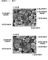
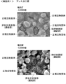
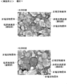
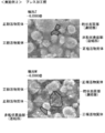
- the present invention in one electron microscope image, a grainy surface portion and a non-granularity surface portion are confirmed on the surface of the connecting portion.
- the present invention is not limited to the case where only one grainy surface portion satisfying the above configuration requirement (1) is confirmed.
- a plurality of granular surface portions satisfying the above-described configuration requirement (1) may be confirmed for one non-granular surface portion. Any two of the plurality of grainy surface portions may partially overlap.
- the “granularity surface portion” can be freely set in the connection portion as long as the above configuration requirement (1) is satisfied.
- the grainy surface may be adjacent to a region where the degree of graininess is substantially the same as that of the grainy surface.
- the granular surface portion may be adjacent to a region having a different degree of granularity from the granular surface portion.
- the grainy surface portion may be set so as not to be adjacent to the region having the same degree of graininess as the grainy surface portion. At least a part of the grainy surface portion may not be adjacent to another region of the connecting portion. At least a part of the grainy surface portion may be adjacent to a substance other than the connection portion. A part of the granular feeling surface part may not be adjacent to another part of the connection part, the positive electrode active material body and the binder.
- the non-granularity surface portion may be adjacent to the region having the same degree of granularity as the non-granularity surface portion.
- the non-granularity surface portion may be adjacent to a region having a different degree of granularity from the non-granularity surface portion.
- the non-granularity surface portion may be set so as not to be adjacent to a region having the same degree of granularity as the non-granularity surface portion. At least a part of the non-granular surface does not have to be adjacent to another region in the connecting portion. At least a part of the non-granular surface may be adjacent to a substance other than the connection part. A part of the non-granular surface may not be adjacent to another part of the connection part, the positive electrode active material, and the binder.
- "in at least one electron microscopic image, a grainy surface portion and a non-granularity surface portion are respectively confirmed on the surface of the connection portion” means that only one electron microscope image shows the connection portion. This includes the case where a granular feeling surface part and a non-granular feeling surface part are confirmed on the surface. Furthermore, in a plurality of electron microscope images, a case where a granular feeling surface part and a non-granular feeling surface part are respectively confirmed on the surface of the connection part is also included. In the latter case, the non-granular surface portions respectively confirmed in a plurality of electron microscope images may be obtained by photographing the same region or different regions. Similarly, the grainy surface portion confirmed in each of the plurality of electron microscope images may be the same region or a different region.
- “has a granular feeling” means that the surface can be visually recognized as granular in an electron microscope image.
- the granularity of the conductive material means that irregularities having the same size as the diameter of the conductive material are formed.
- the unevenness at the same level as the diameter of the conductive material means that the distance between the vertices of the protrusion is the same as or close to the diameter of the conductive material.
- the name of the granular surface may be changed to the granular surface.
- a non-granular feeling surface part having less granular feeling than a granular feeling surface part means that one non-granular feeling surface part in one electron microscope image is one granular feeling surface part in the same electron microscope image. It means that there is no graininess of the conductive material.
- One non-granular surface part in one electron microscopic image may have less granularity of the conductive material than two or more granular surface parts in the same electron microscopic image.
- One non-granular surface in one electron microscope image may be less grainy of the conductive material than all granular surfaces in the same electron microscope image.
- the “average diameter of a conductive material having a diameter of 1 ⁇ m or less” is an average diameter of a conductive material having a diameter of 1 ⁇ m or less contained in a connecting portion.
- the “average diameter of the conductive material having a diameter of 1 ⁇ m or less” may be, for example, any of the following cases. In the first case, when the two-dimensional shape of the conductive material included in the connection portion is circular and / or when the three-dimensional shape of the conductive material is spherical, “the average of the conductive material having a diameter of 1 ⁇ m or less is used.
- the diameter may be the diameter of a sphere corresponding to the volume, or the maximum length of a plane or a cross section of the conductive material included in the connection portion.
- the “average diameter of the conductive material having a diameter of 1 ⁇ m or less” means any one of a plurality of conductive materials having a diameter of 1 ⁇ m or less included in the connecting portion.
- the average diameter of one conductive material may be used, or the average diameter of a plurality of conductive materials having a diameter of 1 ⁇ m or less included in the connection portion may be used.
- the “average diameter of one conductive material having a diameter of 1 ⁇ m or less included in the granular surface portion” and “the average diameter of one conductive material having a diameter of 1 ⁇ m or less included in the non-granular surface portion” are also described above. This is the same as the “average diameter of a conductive material having a diameter of 1 ⁇ m or less” when the connecting portion includes only one conductive material having a diameter of 1 ⁇ m or less.
- the area of the grainy surface in the electron microscope image is 10% of the value obtained by multiplying the square of the average diameter of the conductive material having a diameter of 1 ⁇ m or less by the square.
- the expression “more than twice” may be any of the following four aspects.
- the area of the granular surface in the electron microscope image is the square of the average diameter of one or a plurality of conductive materials having a diameter of 1 ⁇ m or less included in the granular surface. It is at least 10 times the value obtained by multiplying the pi by the pi.
- the area of the grainy surface in the electron microscope image is 1% of the average diameter of a plurality of conductive materials having a diameter of 1 ⁇ m or less contained in the grainy surface and the non-granularity surface in the electron microscope image. It is at least 10 times the value obtained by multiplying the square of / 2 by the pi.
- the area of the non-granular surface part in the electron microscope image is a value obtained by multiplying the square of the average diameter of the conductive material having a diameter of 1 ⁇ m or less by the pi. "10 times or more” may be any of the following four embodiments.
- the area of the non-granular surface part in the electron microscope image is set to be ⁇ of the average diameter of one or more conductive materials having a diameter of 1 ⁇ m or less included in the non-granular surface part. It is 10 times or more the value obtained by multiplying the raised value by the pi.
- the binarization process for distinguishing an electron microscope image into a dark region indicating a concave portion and a bright region indicating a convex portion is to compare the brightness or luminance of the electron microscope image with a threshold value, This is image processing for binarizing brightness or luminance.
- the threshold value may be any value as long as it is possible to distinguish the clearly concave region from the clearly convex region in the electron microscope image. That is, the binarization processing using a threshold value that includes a region that is clearly a convex part in the electron microscope image in the dark region is not included in the binarization process of the electron microscope image of the present invention.
- the threshold may be changed for each electron microscope image. Further, the same threshold value may be used for different electron microscope images.
- the threshold value is the ratio of the area of the dark region occupying at least a part of the non-granular surface, the ratio of the area of the dark region occupying at least a part of the granular surface, and the ratio of the area of the dark region occupying the entire electron microscope image. May be changed in each calculation. Further, the ratio of the area of the dark region occupying at least a part of the non-granular feeling surface portion, the ratio of the area of the dark region occupying at least a part of the granular feeling surface portion, and the ratio of the area of the dark region occupying the entire electron microscope image are described. The same threshold may be used for the calculation.
- the threshold used for calculating the ratio of the area of the dark region and the threshold used for calculating the ratio of the area of the dark region occupying at least a part of the grainy surface portion are the same.
- the area of the dark region occupying at least a part of the non-grain feeling surface part Is preferably the same as the threshold used for calculating the ratio of the area of the dark region in the entire electron microscope image.
- the two thresholds may be different.
- the ratio of the area of the dark region occupying at least a part of the granular feeling surface portion is preferably the same as the threshold used for calculating the ratio of the area of the dark region in the entire electron microscope image.
- the two thresholds may be different.
- the term "binary processing for an electron microscope image" includes performing binarization processing on the entire electron microscope image and performing binarization processing on a part of the electron microscope image.
- the ratio of the area of the dark region occupying at least a part of the non-granular sensible surface part in the first electron microscope image is such that the dark area occupying at least a part of the granular sensible surface part in the first electron microscopic image
- "Is smaller than the ratio of the area of the dark area” means that the ratio of the area of the dark region occupying at least a part of the one non-granular feeling surface portion in the first electron microscope image is one granular feeling in the first electron microscope image. It means that it is smaller than the ratio of the area of the dark region to at least a part of the surface portion.
- the ratio of the area of the dark region occupying at least a part of one non-granular surface part in the first electron microscope image occupies at least a part of each of the two or more granular surface parts in the first electron microscope image. It may be smaller than the ratio of the area of the dark region.
- the ratio of the area of the dark region occupying at least a part of one non-granular surface part in the first electron microscopic image is such that the area ratio of the dark area occupying at least a part of each of the granular surface parts in the first electron microscopic image is small.
- the area ratio may be smaller than the area ratio.
- “at least a part of the non-granular surface part in the first electron microscope image” may be a part of one non-granular surface part in the first electron microscope image, The whole non-granular surface portion in the image may be used.
- “at least a part of the non-granular surface part in the first electron microscope image” is a part of the non-granular surface part in the first electron microscope image, A part of the grainy surface can be freely set in the non-granularity surface in the first electron microscope image.
- a part of the non-granular feeling surface portion in the first electron microscope image is adjacent to a region in the first electron microscope image in which the ratio of the area of the dark region is substantially the same as that of the non-granular feeling surface portion.
- a part of the non-granular surface part in the first electron microscope image may be adjacent to a region in the first electron microscopic image in which the area ratio of the dark region is different from that of the part of the non-granular surface part.
- a part of the non-granular surface in the first electron microscopic image may be adjacent to a region in which the degree of granularity is substantially the same as a part of the non-granular surface in the first electron microscopic image.
- a part of the non-granular surface in the first electron microscope image may be adjacent to a region in the degree of granularity different from that of the non-granular surface in the first electron microscopic image.
- the same definition is applied to “at least a part of the non-granular surface part in the second electron microscope image” and “at least a part of the non-granular surface part in the fourth electron microscope image” in the present invention.
- “at least a part of the grainy surface part in the first electron microscope image” may be a part of one grainy surface part in the first electron microscope image, and may be a part of the one grainy surface part in the first electron microscope image. It may be one whole granular surface portion.
- “at least a part of the grainy surface portion in the first electron microscope image” is a part of the grainy surface portion in the first electron microscope image
- the grainy surface in the first electron microscope image A part of the part can be freely set in the grainy surface part in the first electron microscope image.
- a part of the grainy surface portion in the first electron microscope image may be adjacent to a region in the first electron microscope image in which the area ratio of the dark region is different from that of the grainy surface portion.
- a part of the grainy surface part in the first electron microscope image may be adjacent to a part in the same degree of graininess as the part of the grainy surface part in the first electron microscope image.
- a part of the grainy surface portion in the first electron microscope image may be adjacent to a region in the degree of graininess different from the part of the grainy surface portion in the first electron microscope image.
- the same definition is applied to “at least a part of the grainy surface part in the third electron microscope image” and “at least a part of the grainy surface part in the sixth electron microscope image” in the present invention.
- non-granular feeling surface portion in the electron microscope image when the electron microscope image is binarized, at least a part may have a dark region, having a dark region It does not have to be.
- the “granular surface part in the electron microscope image” may have at least a part of a dark region when the electron microscope image is subjected to the binarization process, and may have a dark region. It is not necessary.
- the area of at least a part of the non-granular feeling surface portion in the first electron microscope image includes the area of the dark region when there is a dark region showing a concave portion in the non-granular feeling surface portion. May be.
- the non-granularity surface portion is a region existing on the surface of the connection portion. Therefore, at least a part of the area of the non-granular surface is a part of the surface of the connecting part.
- the same definition applies to “the area of at least a part of the non-granular surface part in the second electron microscope image” and “the area of at least a part of the non-granular surface part in the fourth electron microscopic image” in the present invention. Is done.
- the area of at least a part of the grainy surface portion in the first electron microscope image may include the area of the dark region when there is a dark region showing a concave portion in the grainy surface portion.
- the grainy surface portion is a region existing on the surface of the connection portion. Therefore, at least a part of the area of the granular feeling surface part is a part of the surface of the connecting part.
- the same definition is applied to “the area of at least a part of the granular surface part in the third electron microscope image” and “the area of at least a part of the granular surface part in the sixth electron microscope image” of the present invention. .
- the present invention may refer to “the dark region occupying at least a part of the non-granular sensible surface portion in the first electron microscopic image”.
- the magnitude relations between the "area ratio" and other ratios or numerical values those other than the above (3) hold for at least one non-granularity surface portion. In the first electron microscope image, this relationship may be established for all the non-granularity surface portions confirmed on the surface of the connection portion.
- the present invention refers to “the area of the dark region occupying at least a part of the grainy surface portion in the first electron microscope image”.
- the exceptions other than the above (3) hold for at least one granular surface portion. In the first electron microscope image, this relationship may be established for all the grainy surface portions observed on the surface of the connection portion.
- the second electron microscope image and the third electron microscope image have different photographing targets” means that at least a part of the photographing target of the second electron microscope image is the third electron microscope image. It means different from at least a part of the imaging target.
- an object to be photographed by the electron microscope image means only a part thereof, and does not include other parts of the surface. Only a part of the imaging target of the second electron microscope image may be the same as a part of the imaging target of the third electron microscope image.
- ⁇ The“ type of electronic image ”in the present invention is determined by the type of signal electrons detected by the electron microscope. For example, when the secondary electrons emitted from the sample are detected by an electron microscope, the type of the electronic image is a secondary electron image. When the backscattered electrons emitted from the sample are detected by the electron microscope, the type of the electron image is a backscattered electron image.
- the ratio of the area of the dark region occupying at least a part of the non-granular surface part in the second electron microscope image is such that the dark area occupying at least a part of the granular surface part in the third electron microscopic image" "Is smaller than the ratio of the area of the non-granular sensation surface portion in the second electron microscopic image, and the ratio of the area of the dark region occupying at least a part of one non-granular sensation surface portion in the second electron microscopic image is one It means that it is smaller than the ratio of the area of the dark region to at least a part of the surface portion.
- the ratio of the area of the dark region occupying at least a part of one non-granular feeling surface part in the second electron microscope image is at least a part of each of the two or more granular feeling surface parts in the third electron microscope image. It may be smaller than the ratio of the area of the dark region occupied.
- the ratio of the area of the dark region occupying at least a part of one non-granular sensible surface part in the second electron microscope image is such that the dark area occupying at least a part of each of the granular sensible surface parts in the third electron microscopic image
- the area ratio may be smaller than the area ratio.
- the present invention refers to “a dark region occupying at least a part of the non-granular sensible surface portion in the second electron microscopic image”.
- a dark region occupying at least a part of the non-granular sensible surface portion in the second electron microscopic image.
- the present invention may refer to “the area of the dark region occupying at least a part of the grainy surface portion in the third electron microscope image”.
- the exceptions other than the above (4) hold for at least one granular surface portion. In the second electron microscope image, this relationship may be established for all the grainy surface portions observed on the surface of the connection portion.
- the fifth electron microscope image has a different imaging target from the fourth electron microscope image
- the photographing target of the electron microscope image refers to only a part thereof, and does not include other parts of the surface. Only a part of the imaging target of the fourth electron microscope image may be the same as all or part of the imaging target of the fifth electron microscope image. Only a part of the imaging target of the fifth electron microscope image may be the same as all or part of the imaging target of the fourth electron microscope image.
- the fourth electron microscope image may be an image obtained by photographing a part of the object to be photographed of the fifth electron microscope image at a magnification larger than the magnification of the fifth electron microscope image.
- the definition of “the seventh electron microscope image is different from the sixth electron microscope image in the imaging target” in the present invention is the same as above.
- the present invention describes “a dark region occupying at least a part of the non-granular sensible surface portion in the fourth electron microscopic image”.
- a dark region occupying at least a part of the non-granular sensible surface portion in the fourth electron microscopic image.
- the “fifth electron microscope image” in the present invention may be an electron microscope image in which a grainy surface portion and a non-granularity surface portion are confirmed, in which a grainy surface portion or a non-granularity surface portion is confirmed.
- the image may be an electron microscope image, or may be an electron microscope image in which neither the grainy surface portion nor the non-granularity surface portion is confirmed.
- the “seventh electron microscopic image” in the present invention may be an electron microscopic image in which a grainy surface portion and a non-granularity surface portion are confirmed, in which a grainy or non-granularity surface portion is confirmed.
- the image may be an electron microscope image, or may be an electron microscope image in which neither the grainy surface portion nor the non-granularity surface portion is confirmed.
- the imaging target of the second electron microscope image may be the same as or different from the imaging target of the first electron microscope image.
- the imaging target of the third electron microscope image is different from the imaging target of the first electron microscope image.
- the imaging target of the third electron microscope image may be the same as or different from the imaging target of the first electron microscope image. Is also good. That is, the imaging target of the third electron microscope image may be the same as or different from the imaging target of the first electron microscope image.
- the imaging target of the fifth electron microscope image may be the same as or different from the imaging target of the second electron microscope image or the third electron microscope image.
- the imaging target of the fifth electron microscope image may be the same as or different from the imaging target of the first electron microscope image or the third electron microscope image.
- the subject of the seventh electron microscope image is different from the subject of the first electron microscope image.
- the imaging target of the seventh electron microscope image may be the same as or different from the imaging target of the second electron microscope image or the third electron microscope image.
- the imaging target of the seventh electron microscope image is different from the imaging target of the third electron microscope image.
- the imaging target of the seventh electron microscope image may be the same as or different from the imaging target of the first electron microscope image or the second electron microscope image.
- the “region containing 10 or more conductive materials having a diameter of 1 ⁇ m or less” is a region where it is possible to visually confirm that it contains 10 or more conductive materials having a diameter of 1 ⁇ m or less. What can be visually confirmed may be, for example, what can be visually confirmed in an electron microscopic image.
- the non-granular surface portion contains a conductive material having a diameter of 1 ⁇ m or less
- the conductive material having a diameter of 1 ⁇ m or less can be visually confirmed on the non-granular surface portion and / or That is, a conductive material having a diameter of 1 ⁇ m or less is exposed at the non-granular surface.
- the granular feeling surface portion includes a conductive material having a diameter of 1 ⁇ m or less”.
- 0.1 C discharge capacity per weight of positive electrode active material particles at 25 ⁇ 2 ° C.” refers to a constant current constant voltage charge (CCCV) of 0.1 C under an environment of 25 ⁇ 2 ° C.
- the constant-current / constant-voltage charging of 0.1 C means charging at a constant current of 0.1 C up to the charging end voltage and then charging at a charging end voltage up to the charging end current.
- the 0.1 C constant current discharge is to discharge to a discharge end voltage at a constant current of 0.1 C.
- the end-of-charge voltage is a maximum value of a charging voltage at which charging can be performed before the function of the secondary battery is deteriorated due to overcharging.
- the charge termination current is the minimum charge current that terminates charging during constant voltage charging.
- the discharge end voltage is a minimum value of a discharge voltage at which a discharge can be performed before the function of the secondary battery is deteriorated due to overdischarge.
- the discharge capacity is the amount of electricity extracted from the battery. In this specification, a general term for a discharge capacity and a charge capacity is called a charge / discharge capacity.
- the charging capacity is the amount of electricity that the battery can store.
- the ratio of the discharge capacity divided by the charge capacity is referred to as charge / discharge efficiency.
- the charge / discharge efficiency is represented by the following equation.
- the unit of the charge / discharge efficiency is “%”.
- Charge / discharge efficiency (discharge capacity / charge capacity) ⁇ 100
- the initial charge / discharge efficiency is a ratio obtained by dividing the discharge capacity in the first charge / discharge by the charge capacity in the first charge / discharge.
- the "half cell produced using the positive electrode for a non-aqueous electrolyte secondary battery” is a cell using a positive electrode for a non-aqueous electrolyte secondary battery as a positive electrode and using lithium as a negative electrode.
- the “half cell produced using the positive electrode for a nonaqueous electrolyte secondary battery” may be referred to as a “positive electrode half cell” or a “positive electrode half cell”.
- the 0.1 C discharge capacity per weight of the positive electrode active material particles at 25 ⁇ 2 ° C. is 90% or more of the maximum discharge capacity
- the positive electrode active material particles at 25 ⁇ 2 ° C. This means that the 0.1 C discharge capacity per weight is 90% or more of the theoretical maximum value of the 0.1 C discharge capacity per weight of the positive electrode active material particles at 25 ⁇ 2 ° C.
- the theoretical maximum value of the 0.1 C discharge capacity per weight of the positive electrode active material particles at 25 ⁇ 2 ° C. may be referred to as a 0.1 C maximum discharge capacity.
- the maximum discharge capacity of 0.1 C per weight of the positive electrode active material particles of the nonaqueous electrolyte secondary battery depends on the material of the positive electrode active material particles, the diameter of the positive electrode active material particles, and the diameter of the positive electrode active material body.
- the positive electrode active material particles include nickel, cobalt, and manganese
- the larger the ratio of nickel the larger the 0.1 C maximum discharge capacity per weight of the positive electrode active material particles tends to be.
- the smaller the diameter of at least one of the diameter of the positive electrode active material particles and the diameter of the positive electrode active material body the larger the 0.1 C maximum discharge capacity tends to be.
- the discharge capacity at a discharge rate other than 0.1 C also depends on the material of the positive electrode active material particles, the diameter of the positive electrode active material particles, and the diameter of the positive electrode active material body.
- Table 1 shows the maximum discharge capacity at 0.1 C for each type (material) of the positive electrode active material particles.
- the 0.1C maximum discharge capacity shown in Table 1 is constant current constant voltage charging at a current of 0.1 C, a charge end voltage of 4.3 V, and a charge end current of 0.02 C in an environment of 25 ⁇ 2 ° C. This is the discharge capacity per positive electrode active material particle weight when constant current discharge is performed at a current of 0.1 C and a discharge end voltage of 3.0 V.
- the 0.1 C maximum discharge capacity shown in Table 1 was calculated without specifying the diameter of the positive electrode active material particles and the diameter of the positive electrode active material body.
- the 0.1 C maximum discharge capacity shown in Table 1 is a value when the diameter of the positive electrode active material particles and the diameter of the positive electrode active material body are in a general range according to the material of the positive electrode active material particles.
- the 0.1 C maximum discharge capacity shown in Table 1 is a 0.1 C discharge capacity measured using a positive half cell.
- NCM is an abbreviation for lithium nickel cobalt manganate.
- NCM111 contains nickel, cobalt and manganese in a ratio of 1: 1: 1.
- NCM523 contains nickel, cobalt and manganese in a ratio of 5: 2: 3.
- NCM622 contains nickel, cobalt and manganese in a ratio of 6: 2: 2.
- NCM811 contains nickel, cobalt and manganese in a ratio of 8: 1: 1.
- NCA is an abbreviation for lithium nickel cobalt aluminum oxide.
- NCA in Table 1 contains nickel, cobalt and aluminum at 80: 15: 5.
- the positive electrode active material particles are “NCM111” and the 0.1 C discharge capacity is 144 mAh / g, even if the diameter of the positive electrode active material particles and the diameter of the positive electrode active material body are not specified, the 0.1 C discharge It can be said that the capacity is 90% or more of the theoretical maximum value.
- the maximum discharge capacity of the battery manufactured using the positive electrode was increased by 0.1 C maximum discharge capacity shown in Table 1. It can be determined using the discharge capacity. For example, a case where the 0.1 C maximum discharge capacity of “NCM7, 1.5, 1.5” is calculated will be described as an example. "NCM7, 1.5, 1.5” contains nickel, cobalt and manganese in a ratio of 7: 1.5: 1.5. Theoretically, if “NCM622” is mixed with 50 wt% and “NCM811” is mixed with 50 wt%, “NCM7, 1.5, 1.5” is obtained.
- 0.1 C maximum discharge capacity of “NCM7, 1.5, 1.5” can be obtained from the following equation.
- the positive electrode active material particles having an arbitrary composition include “NCM111” a1 [wt%], “NCM523” a2 [wt%], “NCM622” a3 [wt%], and “NCM811” a4 [wt%].
- [wt%] is obtained by mixing NCA with a5 [wt%]
- the positive electrode active material particles having an arbitrary composition can be obtained from the following formula.
- 0.1C maximum discharge capacity of arbitrary composition 155 (intermediate value of 0.1C maximum discharge capacity of NCM111) ⁇ (a1 / 100) +165 (intermediate value of 0.1 C maximum discharge capacity of NCM523) ⁇ (a2 / 100) +175 (intermediate value of 0.1 C maximum discharge capacity of NCM622) ⁇ (a3 / 100) +195 (intermediate value of 0.1 C maximum discharge capacity of NCM811) ⁇ (a4 / 100) +195 (intermediate value of NCA 0.1C maximum discharge capacity) x (a5 / 100)
- 0 ⁇ a1 ⁇ 100 0 ⁇ a2 ⁇ 100 0 ⁇ a3 ⁇ 100 0 ⁇ a4 ⁇ 100 0 ⁇ a5 ⁇ 100 a1 + a2 + a3 + a4 + a5 100
- At least one (one) of a plurality of options includes all possible combinations of the plurality of options. At least one (one) of the plurality of options may be any one of the plurality of options, or may be all of the plurality of options. For example, at least one of A, B, and C may be only A, may be only B, may be only C, may be A and B, and may be A and C. Or B and C, or A, B and C.
- the positive electrode for a non-aqueous electrolyte secondary battery and the non-aqueous electrolyte secondary battery of the present invention do not specify the number in the claims, and when translated into English, a plurality of elements are singly displayed. You may have.
- the positive electrode for a non-aqueous electrolyte secondary battery and the non-aqueous electrolyte secondary battery of the present invention do not specify the number in the claims, and when translated into English, one element is represented by one. You may have only one.
- the terms mounted, connected, coupled, and supported are used broadly. Specifically, it includes not only direct attachment, connection, connection and support, but also indirect attachment, connection, connection and support. Furthermore, connected and coupled are not limited to physical or mechanical connections / couplings. They also include direct or indirect electrical connections / couplings.
- the term "preferred” is non-exclusive. “Preferred” means “preferred but not limited to”. In this specification, a configuration described as “preferred” has at least the above-described effects obtained by the above-described configuration (1). Also, in this specification, the term “may” is non-exclusive. “May be” means “may be, but not limited to.” In the present specification, the configuration described as “may” has at least the above-described effect obtained by the configuration (1).
- the positive electrode for a non-aqueous electrolyte secondary battery using the positive electrode active material containing lithium and nickel of the present invention is compared with the conventional positive electrode for a non-aqueous electrolyte secondary battery using the positive electrode active material containing lithium and nickel.
- the durability of the battery can be increased while improving the battery characteristics.
- FIG. 1 is a cross-sectional perspective view of a nonaqueous electrolyte secondary battery to which a positive electrode for a nonaqueous electrolyte secondary battery according to a specific example of an embodiment of the present invention is applied. It is the electron microscope image of 2,000 times, 4,000 times, and 6,000 times of the place X of the surface of the positive electrode of Example 1 of this invention.
- 4 is an electron microscope image of the surface of the positive electrode of Comparative Example 1 at 2,000, 4,000, and 6,000 times.
- 6 is a 6,000-fold electron microscope image of the surface of the positive electrode before pressing in Comparative Example 1.
- 9 is 2,000, 4,000, and 6,000 times electron microscope images of the surface of the positive electrode of Comparative Example 2.
- 9 is a 6,000-fold electron microscope image of the surface of the positive electrode before pressing in Comparative Example 2.
- 9 is 2,000, 4,000, and 6,000 times electron microscope images of the surface of the positive electrode of Comparative Example 3.
- 13 is a 6,000-fold electron microscope image of the surface of the positive electrode before pressing in Comparative Example 3.
- the positive electrode 1 for a non-aqueous electrolyte secondary battery has a positive electrode active material body 2, a binder 3, a connecting portion 5, and a current collector 6.
- the positive electrode active material body 2 is formed by aggregating positive electrode active material particles 2a containing lithium and nickel.
- the binder 3 is water-soluble or water-dispersible.
- the connecting portion 5 connects the positive electrode active material members 2 to each other.
- the connection part 5 includes the conductive material 4.
- the conductive material 4 is a conductive material having a diameter of 1 ⁇ m or less.
- the connecting portion 5 does not include a conductive material other than the conductive material 4.
- the positive electrode 1 for a non-aqueous electrolyte secondary battery is pressed in the thickness direction of the positive electrode 1.
- the thickness direction of the positive electrode 1 is the thickness direction of the current collector 6.
- FIG. 1 shows a schematic diagram of an electron microscope image A obtained by photographing the surface of the positive electrode 1 with an electron microscope in addition to the configuration diagram of the positive electrode 1.
- the binder 3 is not reflected in the electron microscope image A. That is, the electron microscope image A is an image photographed under the condition that the binder 3 is not reflected.
- the photographing conditions of the electron microscope image include an acceleration voltage, a distance between the object and the photographing unit, a photographing magnification, a type of the electronic image, and the like.
- the surface of the connecting portion 5 has a granular surface 5b having the granularity of the conductive material 4 and a non-particle surface less granular than the granular surface 5b.
- the grainy surface portion 5a is confirmed.
- the non-granular surface portion 5a is made of a material other than the conductive material 4 that covers the conductive material 4. That is, the conductive material 4 is covered with a substance other than the conductive material 4 on a part of the surface of the connecting portion 5. On the other hand, the conductive material 4 is exposed almost all over the granular feeling surface portion 5b.
- FIG. 1 also shows a schematic diagram of an electron microscope image B of the surface of a conventional positive electrode for a non-aqueous electrolyte secondary battery having a positive electrode active material body 22 containing lithium and nickel as a comparison object.
- the surface of the connecting portion 25 that connects the positive electrode active material members 22 has the granularity of the conductive material 24 as a whole. That is, in the electron microscope image B, the surface of the connecting portion 25 does not have a portion without granularity.
- the conductive material 24 is exposed on the entire surface of the connecting portion 25.
- the connecting member 5 is connected.
- the connection between the conductive members 4 in the portion 5 is less likely to be broken than in the conventional positive electrode.
- the conductivity of the electrons by the connecting portion 5 is improved, and the electrode resistance of the battery is reduced.
- the charging and discharging efficiency is improved as compared with the conventional non-aqueous electrolyte secondary battery.
- the conductive material 4 is covered with a material other than the conductive material 4 on a part of the surface of the connection part 5, a part of the positive electrode active material body 2 is fixed by the connection part 5. Therefore, even when the positive electrode active material body 2 expands or contracts during charging and discharging of the battery, cracks in the positive electrode active material body 2 are less likely to occur than in the conventional positive electrode. Accordingly, since the occurrence of cracks in the positive electrode active material body 2 is suppressed, a decrease in charge / discharge efficiency due to use of the battery is suppressed. In addition, as compared with the conventional nonaqueous electrolyte secondary battery, the deterioration of the positive electrode due to the generation of cracks in the positive electrode active material body 2 can be suppressed.
- the conductive material 4 is covered with a material other than the conductive material 4 on a part of the surface of the connecting part 5, the conductive material 4 is partially covered with the positive electrode active material body 2 of the connecting part 5. Also, it can be estimated that the conductive material 4 is covered with a substance other than the conductive material 4. This makes it difficult for the electrolytic solution to come into contact with the surface of the positive electrode active material body 2 through the connecting portion 5. That is, it is possible to prevent the electrolyte from coming into contact with the positive electrode active material body 2 through the connection portion 5 while ensuring the ease of infiltration of the electrolyte solution into the connection portion 5.
- the electrolyte does not easily come into contact with the positive electrode active material body 2, the electrolyte is less likely to be electrolyzed even when the battery is used at a high voltage. Therefore, even when used at a higher voltage, deterioration of the battery due to electrolysis of the electrolyte can be suppressed as compared with a conventional nonaqueous electrolyte secondary battery.
- the connecting portion 5 has the granular feeling surface portion 5 b having a granular feeling and the non-granular feeling surface portion 5 a having no granular feeling, so that the positive electrode active material containing lithium and nickel is provided.
- the battery characteristics can be improved and the durability of the battery can be improved.
- the positive electrode 1 for a non-aqueous electrolyte secondary battery is in a sheet shape.
- the positive electrode 1 for a non-aqueous electrolyte secondary battery has a positive electrode active material body 2, a binder 3, a connecting portion 5, and a current collector 6.
- the connecting portion 5 connects the positive electrode active material members 2 to each other.
- the connection part 5 includes a plurality of conductive materials 4.
- the conductive material 4 is a conductive material having a diameter or thickness of 1 ⁇ m or less.
- the connecting portion 5 does not include a conductive material other than the conductive material 4.
- the positive electrode 1 for a non-aqueous electrolyte secondary battery is configured to be able to occlude and release lithium ions.
- the positive electrode 1 for a non-aqueous electrolyte secondary battery is pressed in a manufacturing process of the positive electrode 1 for a non-aqueous electrolyte secondary battery.
- the positive electrode 1 for a non-aqueous electrolyte secondary battery is pressed in the thickness direction of the positive electrode 1.
- the binder 3 connects the positive electrode active material members 2 to each other.
- the binder 3 connects a part of the connecting part 5 and another part of the connecting part 5.
- the binder 3 connects the positive electrode active material body 2 and the connecting portion 5.
- the binder 3 connects a part of the positive electrode active material body 2 and the connecting portion 5 to the current collector 6.
- the binder 3 is a water-soluble binder or a water-dispersible binder.
- a binder soluble in water and a binder dispersible in water may be collectively referred to as an aqueous binder.
- the aqueous binder is, for example, an acrylic binder containing an acrylic resin as a main component.
- the positive electrode active material body 2 is a secondary particle formed by agglomeration of the positive electrode active material particles 2a, which are primary particles.
- the positive electrode active material particles 2a and the positive electrode active material body 2 are in the form of particles.
- the positive electrode active material body 2 contains a composite oxide containing lithium and nickel.
- the positive electrode active material body 2 may include another metal in addition to lithium and nickel. That is, the positive electrode active material body 2 may include a composite oxide containing lithium, nickel, and another metal.
- the nickel content of the positive electrode active material body 2 is 30 mol% or more.
- the nickel content of the positive electrode active material body 2 may be 30 mol%, 50 mol%, or 80 mol%.
- the nickel content of the positive electrode active material body 2 is the same as the nickel content of the positive electrode active material particles 2a.
- the nickel content of the positive electrode active material body 2 is a ratio of nickel to a metal element contained in the positive electrode active material particles 2a.
- the conductive material 4 may be in the form of particles or may be in a shape other than the particles.
- the conductive material 4 may have a spherical shape or a shape other than a spherical shape.
- the conductive material 4 having a diameter of 1 ⁇ m or less is, for example, carbon black, fine graphite and carbon nanotube.
- the carbon black may be a domain or an aggregate.
- the conductive material 4 is a carbon nanotube that is long in the axial direction
- the outer shape of the carbon nanotube in a plane perpendicular to the axial direction of the carbon nanotube is circular
- the diameter of the carbon nanotube is perpendicular to the axial direction of the carbon nanotube.
- the outer diameter of the carbon nanotube in the plane can be used. That is, when the outer shape of the carbon nanotube in a plane perpendicular to the axial direction of the carbon nanotube is circular, the outer diameter of the plane perpendicular to the axial direction of the carbon nanotube can be used as the diameter of the carbon nanotube.
- the thickness of the conductive material 4 may exceed 1 ⁇ m, and the thickness of the conductive material 4 may be 1 ⁇ m or less.
- the longitudinal length of the conductive material 4 may exceed 1 ⁇ m, and the longitudinal length of the conductive material 4 may be 1 ⁇ m or less.
- the connection portion 5 may include only one type of conductive material 4 or a plurality of types of conductive material 4.
- the current collector 6 preferably contains aluminum.
- the current collector 6 may be, for example, an aluminum foil.
- the current collector 6 may be, for example, a metal foil of an aluminum alloy containing aluminum.
- the current collector 6 may not include aluminum.
- FIG. 1 shows a schematic diagram of an electron microscope image A of the surface of the positive electrode 1.
- the electron microscope image A is an image taken under the condition that the binder 3 is not reflected. Specifically, the electron microscope image A is an image captured at an acceleration voltage of 5 kV or more and 20 kV or less.
- the electron microscope image A may be, for example, an electron microscope image captured by a scanning electron microscope or an electron microscope image captured by a field emission scanning electron microscope.
- the electron microscope image A is a secondary electron image, the type of the electronic image is not limited to the secondary electron image.
- the electron microscope image A may be a reflected electron image.
- a plurality of positive electrode active material bodies 2 and connecting portions 5 are present in the electron microscope image A of FIG.
- the connecting portion 5 is configured by a plurality of independent portions, but is not limited to this configuration.
- the connecting portion 5 may be a single connected object.
- a grainy surface portion 5b having a graininess of the conductive material 4 and a non-granularity surface portion 5a having less graininess than the grainy surface portion 5b are confirmed.
- the grainy surface portion 5b is independent from other portions of the connecting portion 5.
- the grainy surface 5b is not adjacent to a region having the same degree of graininess as the grainy surface 5b.
- the grainy surface 5b is not adjacent to a region having a different degree of graininess from the grainy surface 5b.
- the non-granular surface portion 5 a is independent of the other portion of the connecting portion 5.
- the non-granularity surface portion 5a is not adjacent to a region having the same degree of granularity as the non-granularity surface portion 5a. In the electron microscope image A, the non-granular surface portion 5a is not adjacent to a region having a different degree of granularity from the non-granular surface portion 5a.
- the area of the non-granular surface part 5a and the area of the granular surface part 5b are obtained by multiplying the square of the average diameter of the conductive material 4 by ⁇ . It is preferably at least 10 times the given value.
- the average diameter may be an average diameter calculated by any method.
- the average diameter may be, for example, a number average particle diameter or a volume average particle diameter.
- the average diameter of the conductive material 4 may be the average diameter of one or a plurality of conductive materials 4 confirmed on the granular feeling surface portion 5b.
- the average diameter of the conductive material 4 may be the average diameter of one or a plurality of conductive materials 4 that are observed on the grained surface portion other than the grained surface portion 5b in the connecting portion 5.
- the average diameter of the conductive material 4 is determined based on at least one conductive material 4 found on the granular feeling surface portion 5b and at least one conductive material 4 found on the connecting portion 5 other than the granular feeling surface portion 5b. May be used.
- the average diameter of the conductive material 4 may be the average diameter of one or a plurality of conductive materials 4 confirmed on the non-granular surface part 5a.
- the average diameter of the conductive material 4 is the non-granular shape other than the non-granular sensible surface portion 5 a in the connecting portion 5.
- the average diameter of one or a plurality of conductive materials 4 confirmed on the sensitive surface portion may be used.
- the average diameter of the conductive material 4 is at least one of the conductive material 4 identified on the non-granular sensible surface portion 5a and at least one of the non-granular sensible surfaces on the connecting portion 5 other than the non-granular sensible surface portion 5a.
- the average diameter of the conductive material 4 may be used.
- the average diameter of the conductive material 4 may be the average diameter of at least one conductive material 4 found on the non-granular surface 5a and at least one conductive material 4 found on the granular surface 5b.
- the average diameter of the conductive material 4 is at least one conductive material 4 confirmed on the non-granular surface portion 5a and at least one conductive material recognized on the granular surface portion other than the granular surface portion 5b in the connecting portion 5.
- An average diameter of 4 may be used.
- the average diameter of the conductive material 4 is at least one conductive material 4 found on the non-granular sensible surface portion other than the non-granular sensible surface portion 5a and at least one conductive material found on the granular sensible surface portion 5b in the connecting portion 5.
- the average diameter of the material 4 may be used.
- the average diameter of the conductive material 4 is such that at least one conductive material 4 confirmed on the non-granular surface other than the non-granular surface 5a at the connecting portion 5 and the granular surface other than the granular surface 5b at the connecting portion 5
- the average diameter of at least one conductive material 4 confirmed on the surface may be used.
- the average diameter of the conductive material 4 is such that the connecting portion 5 has a non-granular surface 5a, a non-granular surface other than the non-granular surface 5a, a granular surface 5b, and a granular surface other than the granular surface 5b.
- the average diameter of at least one conductive material 4 confirmed in at least one of the portions may be used.
- the granular feel surface portion 5b preferably includes a region including ten or more conductive materials 4.
- the area of the non-granular surface part 5a is preferably equal to or larger than the area of a region including ten or more conductive materials 4 in the granular surface part 5b.
- the non-granular surface portion 5a may be a region including ten or more conductive materials 4.
- the magnification of the electron microscope image A is preferably from 2,000 to 8,000.
- the magnification of the electron microscope image A may be, for example, 4,000 times or 6,000 times.
- the magnification of the electron microscope image A is particularly preferably 4,000 times or more.
- the connecting portion 5 has one or a plurality of granular feeling surface portions 5b.
- the connecting portion 5 has one or a plurality of non-granular surface portions 5a.
- the conductive material 4 is exposed on the granular feeling surface portion 5b.
- the conductive material 4 is not exposed on the non-granular surface portion 5a.
- substances other than the conductive material 4 are confirmed on the non-granular surface portion 5a.
- the conductive material 4 and a substance other than the conductive material 4 may be confirmed on the non-granular surface portion 5a.
- the connecting portion 5 can be confirmed by a plurality of electron microscope images (not shown) in which a plurality of portions at least partially inconsistent on the surface of the positive electrode 1 are photographed.
- a granular feeling surface portion 5b and a non-granular feeling surface portion 5a are confirmed on the surface of the connecting portion 5, respectively. Therefore, the grainy surface portion 5b and the non-granularity surface portion 5a confirmed in the connecting portion 5 are not formed by accident depending on how the electron microscope image is taken. If this feature can be confirmed in a plurality of electron microscope images, there may be an electron microscope image in which the granular surface 5b or the non-granular surface 5a is not recognized on the surface of the connecting portion 5.
- the granularity of the conductive material 4 on the surface portion 5b is substantially the same as the granularity of the conductive material 24 on the connecting portion 25 of the conventional positive electrode.
- a plurality of conductive materials 4 are confirmed on the granular surface portion 5b.
- the electron microscope image A can be distinguished into a dark region indicating a concave portion on the surface of the positive electrode 1 and a bright region indicating a convex portion on the surface of the positive electrode 1. Further, by performing the binarization processing, the area of the dark region can be calculated. Also, the area of the bright region can be calculated.
- the electron microscope image A includes a gap between the positive electrode active material members 2, a gap between the positive electrode active material member 2 and the connecting portion 5, and a gap between a part of the connecting portion 5 and another portion of the connecting portion 5. I do. Note that the positive electrode active material body 2 or the connecting portion 5 exists behind such a gap even if it cannot be confirmed in the electron microscope image A of the surface of the positive electrode 1.
- a portion where the brightness or the brightness of the image becomes equal to or less than the threshold value due to the binarization processing of the electron microscope image A is included in the dark region.
- Such a gap in the electron microscope image A may include a portion where the brightness or brightness of the image exceeds the threshold value due to the binarization processing of the electron microscope image A.
- the ratio Rc of the area of the dark region to the entire electron microscope image A is somewhat larger than zero, but does not become extremely large.
- the ratio Rc of the area of the dark region in the electron microscope image A is, for example, about 15%.
- Rb be the ratio of the area of the dark region occupying at least a part of the grainy surface portion 5b in the electron microscope image A.
- the ratio of the area of the dark region occupying at least a part of the non-granular surface portion 5a in the electron microscope image A is defined as Ra.
- the concave portion between the conductive materials 4 in the granular feeling surface portion 5b of the electron microscope image A is included in the dark region by the binarization process. Therefore, the ratio Rb of the area of the dark region occupying at least a part of the grainy surface portion 5b in the electron microscope image A is larger than zero.
- the ratio Ra of the area of the dark region occupying at least a part of the non-granular surface part 5a in the electron microscope image A is small.
- the ratio Ra of the area of the dark region occupying at least a part of the non-granular feel surface portion 5a of the electron microscope image A may be zero or may be larger than zero.
- the ratio Ra of the area of the dark region occupying at least a part of the non-granular surface portion 5a in the electron microscope image A is larger than the ratio Rb of the area of the dark region occupying at least a portion of the granular surface portion 5b in the electron microscope image A. Is also small.
- the comparison can be made by using numerical values such as a ratio Ra of the area of the dark region and a ratio Rb of the area of the dark region of the granular surface portion 5b.
- At least a part of the non-granular surface part 5a in the electron microscopic image A for calculating the ratio of the area of the dark region may be a part of the non-granular surface part 5a in the electron microscopic image A.
- the entire grainy surface portion 5a may be used.
- At least a part of the grainy surface 5b in the electron microscope image A for calculating the ratio of the area of the dark region may be a part of the grainy surface 5b in the electron microscope image A, or the grainy surface in the electron microscope image A.
- the entire part 5b may be used.
- the area ratio of at least a part of the non-granular surface part 5a in the electron microscope image A for calculating the ratio of the area of the dark region is obtained by multiplying the square of the average diameter of the conductive material 4 by ⁇ . It is preferably at least 10 times the value obtained in this way.
- the average diameter of the conductive material 4 is the same as the average diameter of the conductive material 4 described in the area of the non-granular surface part 5a and the area of the granular surface part 5b.
- At least a part of the grainy surface portion 5b in the electron microscope image A for calculating the ratio of the area of the dark region is preferably a region including ten or more conductive materials 4. It is preferable that the area of the non-granular surface 5a in the electron microscope image A for calculating the ratio of the area of the dark region is equal to or larger than the area of the granular surface 5b including ten or more conductive materials 4. Alternatively, the area of the non-granular surface portion 5a in the electron microscope image A for calculating the ratio of the area of the dark region may be a region including ten or more conductive materials 4.
- This magnitude relationship between the ratio Ra and the ratio Rb is determined not only by one electron microscope image A but also by a plurality of electron microscope images (not shown) obtained by photographing a plurality of locations on the surface of the positive electrode 1 that are at least partially inconsistent. To establish. If this relationship is established by the plurality of electron microscope images, there may be an electron microscope image in which this relationship is not established. Depending on the electron microscope image, even the grainy surface portion 5b where the graininess can be confirmed may have only a bright region due to the binarization processing. That is, the ratio Rb becomes zero or a value close to zero. In this case, the ratio Rb is equal to the ratio Ra, or the ratio Rb is smaller than the ratio Ra.
- the ratio Ra of at least a part of the dark region of the non-granular surface portion 5a in the electron microscope image A is half or less of the ratio Rb of at least a part of the dark region of the granular surface portion 5b in the electron microscope image A.
- This relationship may be established not only with one electron microscope image A, but also with a plurality of electron microscope images (not shown) in which a plurality of locations at least partially inconsistent on the surface of the positive electrode 1 are photographed.
- this relationship is established in at least one electron microscope image, there may be an electron microscope image in which this relationship is not established. That is, there may be both an electron microscope image in which the ratio Ra is less than half the ratio Rb and an electron microscope image in which the ratio Ra exceeds half the ratio Rb.
- the ratio Ra of at least a part of the dark region of the non-granular feel surface portion 5a in the electron microscope image A may be less than 15% or less than 10%. In this case, the ratio Ra of at least a part of the dark region of the non-granular surface portion 5a is not too large.
- the ratio Ra may be within the above numerical range.
- the ratio Rb of at least a part of the dark region of the grainy surface portion 5b in the electron microscope image A may be 10% or more, or may be 15% or more. In this case, the ratio Rb of at least a part of the dark region of the granular feeling surface portion 5b is not too small.
- the ratio Rb may be within the above numerical range.
- the ratio Ra of the dark region of at least a part of the non-granular feel surface portion 5a in the electron microscope image A may be smaller than the ratio Rc of the dark region of the electron microscope image A.
- the ratio Rc of the dark area of the electron microscope image A does not become extremely large.
- the ratio Ra of at least a part of the dark region of the non-granular feeling surface portion 5a is not too large.
- This relationship may be established in a plurality of electron microscope images (not shown) in which a plurality of portions at least partially inconsistent on the surface of the positive electrode 1 are photographed. There may be both an electron microscope image in which this relationship is established and an electron microscope image in which this relationship is not established.
- the electron microscope image A corresponds to the fourth electron microscope image in the present invention.
- the ratio Rb of at least a part of the dark region of the grainy surface portion 5b in the electron microscope image A may be equal to or more than the ratio Rc of the dark region of the electron microscope image A.
- the ratio Rc of the dark region of the electron microscope image A is somewhat larger than zero. Therefore, the ratio Rb of at least a part of the dark region of the granular feeling surface portion 5b is not too small.
- This relationship may be established in a plurality of electron microscope images (not shown) in which a plurality of portions at least partially inconsistent on the surface of the positive electrode 1 are photographed. There may be both an electron microscope image in which this relationship is established and an electron microscope image in which this relationship is not established.
- the ratio Ra of the area of the dark region occupying at least a part of the non-granular surface portion 5a is not too large, the following effects can be obtained. Since the connection between the conductive members 4 at the connecting portion 5 is hard to be disconnected, the charge / discharge efficiency can be improved. Furthermore, since cracks are less likely to occur in the positive electrode active material body 2, deterioration of the positive electrode 1 can be suppressed. In addition, since the electrolyte is less likely to be electrolyzed, deterioration of the battery can be suppressed. When the ratio Rb of the area of the dark region occupying at least a part of the granular surface portion 5b is not too small, the electrolyte can easily permeate the connecting portion 5. Thereby, the degree of freedom of movement of lithium ions in the connecting portion 5 can be secured. Therefore, the improvement of the charge / discharge efficiency of the battery due to the non-granular feeling surface portion 5a is not prevented.
- the threshold value for binarizing the electron microscope image A is preferably as follows.
- the “ratio Ra of the area of the dark region occupying at least a part of the non-granular surface portion 5a” is referred to as “the ratio Ra of at least a part of the dark region of the non-granular surface portion 5a”
- the ratio Rb of the area of the dark region occupying at least a portion of the sensitive surface portion 5b is referred to as "the ratio Rb of the dark region of at least a portion of the granular surface portion 5b”
- the “ratio of the dark region occupying the electron microscope image A” Rc ” may be referred to as“ ratio Rc of dark area of electron microscope image A ”.
- At least a part of the dark region of the non-granular surface part 5a Is preferably the same as the threshold value of the binarization process used for calculating the ratio Ra of the binarization process and the threshold value of the binarization process used for calculating the ratio Rb of at least a part of the dark region of the granular surface portion 5b.
- the ratio Ra of at least a part of the dark region of the non-granular feeling surface portion 5a obtained by the binarization processing of the electron microscope image A is the granularity obtained by the binarization processing of the electron microscope image A using the same threshold value. It is smaller than the ratio Rb of at least a part of the dark area of the sensing surface portion 5b.
- the ratio Ra of at least a part of the dark region of the non-granular surface part 5a obtained by the binarization processing of the electron microscope image A is the granular surface obtained by the binarization processing of the electron microscope image A using the same threshold value. It is preferable that the ratio be equal to or less than half the ratio Rb of at least a part of the dark region of the portion 5b.
- the calculation of the ratio Ra of at least a part of the dark region of the non-granular surface part 5a is preferably the same as the threshold used for calculating the ratio Rc of the dark area of the electron microscope image A.
- the ratio Ra of at least a part of the dark area of the non-granularity-sensitive surface portion 5a obtained by the binarization processing of the electron microscope image A is obtained by the binarization processing of the electron microscope image A using the same threshold value. It is preferable that the ratio is smaller than the ratio Rc of the dark area of the microscope image A.
- the ratio Rb of at least a part of the dark region of the grainy surface part 5b When comparing the ratio Rb of at least a part of the dark region of the grainy surface part 5b with the ratio Rc of the dark region of the electron microscope image A, it is used for calculating the ratio Rb of at least part of the dark region of the grainy surface part 5b. It is preferable that the threshold value and the threshold value used for calculating the ratio Rc of the dark region of the electron microscope image A be the same. For example, the ratio Rb of at least a part of the dark region of the granular surface portion 5b obtained by the binarization processing of the electron microscope image A is the electron microscope obtained by the binarization processing of the electron microscope image A using the same threshold value. It is preferable that the ratio is larger than the dark area ratio Rc of the image A.
- the positive electrode 1 for a non-aqueous electrolyte secondary battery is manufactured, for example, by the following method.
- the positive electrode active material body 2, the water-soluble or water-dispersible binder 3, the conductive material 4, and a solvent or dispersion medium containing water are mixed to prepare a slurry.
- the binder 3 is water-soluble, it is preferable that 50 wt% or more is water with respect to 100 wt% of the solvent.
- the prepared slurry is applied to the current collector 6. Thereafter, the slurry is dried.
- the drying temperature of the slurry is, for example, about 50 ° C. to 130 ° C.
- the dried slurry and the current collector 6 are pressed in the thickness direction of the current collector 6 so that the obtained positive electrode 1 has a desired electrode density.
- the positive electrode 1 for a non-aqueous electrolyte secondary battery is obtained.
- the slurry may contain various additives such as a thickener and a pH adjuster. Additives include substances that do not evaporate at the drying temperature of the slurry.
- a thickener for example, a cellulose derivative, an acrylic resin, or the like can be used.
- the thickener is not limited to the thickener exemplified above.
- the binder 3 and the thickener do not appear in the electron microscope image A. That is, the electron microscope image A is an image taken under the condition that the binder 3 and the thickener are not reflected.
- FIG. 2 is a schematic cross-sectional view of a nonaqueous electrolyte secondary battery 11 manufactured using the positive electrode 1 for a nonaqueous electrolyte secondary battery according to a specific example of the embodiment of the present invention.
- the non-aqueous electrolyte secondary battery 11 shown in FIG. 2 is an example of a non-aqueous electrolyte secondary battery manufactured using the positive electrode 1 for a non-aqueous electrolyte secondary battery of the above embodiment.
- the non-aqueous electrolyte secondary battery 11 includes the positive electrode 1 for a non-aqueous electrolyte secondary battery, the negative electrode 12, two separators 13, a container 14, a lid 15, and a non-aqueous electrolyte not shown.
- the positive electrode 1, the negative electrode 12 and the two separators 13 are housed in a rectangular cylindrical container 14.
- the positive electrode 1, the negative electrode 12, and the two separators 13 are wound in a prismatic shape.
- the separator 13 is impregnated with a non-aqueous electrolyte.
- the opening of the container 14 is closed by a lid 15.
- the negative electrode 12 is configured to be able to occlude and release lithium ions.
- the negative electrode 12 includes a negative electrode active material.
- the negative electrode active material for example, one or two or more selected from a carbon material, an alloy, and a metal oxide can be used.
- the separator 13 insulates the positive electrode 1 and the negative electrode 12.
- the separator 13 is configured to be able to hold an electrolytic solution.
- the non-aqueous electrolyte contains a non-aqueous solvent (a solvent not containing water) and an electrolyte. The electrolyte is dissolved in a solvent that does not contain water.
- the negative electrode 12, the separator 13, the container 14, the lid 15, the non-aqueous electrolyte, and the like those used in general non-aqueous electrolyte secondary batteries can be used.
- the 0.1 C discharge capacity per weight of the positive electrode active material particles at 25 ⁇ 2 ° C. of the nonaqueous electrolyte secondary battery 11 is determined by the material of the positive electrode active material particles 2a, the diameter of the positive electrode active material particles 2a, and the positive electrode active material body. 2, which is 90% or more of the maximum discharge capacity depending on the diameter.
- the 0.1 C discharge capacity is 90% or more of the maximum discharge capacity, the nonaqueous electrolyte secondary battery 11 is at a level that can sufficiently withstand practical use.
- the positive electrode active material body 2 and the connecting portion 5 are not peeled off from the current collector 6. That is, in the positive electrode 1 for a non-aqueous electrolyte secondary battery, the positive electrode active material body 2 and the connecting portion 5 are connected to the current collector 6 with such a connection strength that they are not separated in the bending resistance test.
- the positive electrode active material body 2 and the connecting portion 5 It is difficult to peel off from the current collector 6. In addition, corrosion of the current collector 6 that causes peeling does not occur. Since the current collector 6 does not corrode, the durability of the nonaqueous electrolyte secondary battery 11 is high.
- the non-aqueous electrolyte secondary battery 11 is manufactured by, for example, the following method.
- the positive electrode 1, the negative electrode 12, and the two separators are wound so that the separator 13 is interposed between the positive electrode 1 and the negative electrode 12. Then, the wound product is stored in the container 14.
- the separator 13 is impregnated with the non-aqueous electrolyte.
- the opening of the container 14 is closed by the lid 15.
- the nonaqueous electrolyte secondary battery 11 using the positive electrode 1 for a nonaqueous electrolyte secondary battery is more charged than a conventional nonaqueous electrolyte secondary battery using a positive electrode active material body containing lithium and nickel.
- the durability can be increased while increasing the discharge efficiency.
- the positive electrode active material body of the present invention may have a depression on the surface. That is, in the electron microscope image of the surface of the positive electrode, a part of the surface of the positive electrode active material body may be included in the dark region by the binarization process. In this case, the ratio of the area of the dark region to the electron microscope image becomes large. The ratio of the area of the dark region occupying at least a part of the grainy surface portion may be smaller than the ratio of the area of the dark region occupying the electron microscope image.
- the ratio of the area of the dark region occupying at least a part of the grainy surface portion is preferably equal to or more than the ratio of the area of the dark region of the electron microscope image excluding the dark region of the surface of the positive electrode active material body in the electron microscope image. preferable.
- the granular feeling surface portion is a portion other than the boundary with the non-granular feeling surface portion, where the conductive material is not exposed. May have some.
- the non-granular surface is a portion where the conductive material is exposed in a portion other than the boundary with the granular surface. May be slightly possessed.
- the grainy surface portion 5 b is independent from other portions of the connecting portion 5.
- the grainy surface portion 5b may be connected to another portion of the connecting portion 5.
- the grainy surface 5b may be adjacent to a region having the same graininess as the grainy surface 5b.
- the grainy surface portion 5b may be adjacent to a region having a different degree of graininess from the grainy surface portion 5b.
- the grainy surface portion 5b may be adjacent to a region where the ratio of the dark region is almost the same as the ratio Rb of the dark region of the grainy surface portion 5b.
- the grainy surface portion 5b may be adjacent to a region in which the ratio of the dark region is different from the ratio Rb of the dark region of the grainy surface portion 5b.
- the magnitude relationship between the ratio of the dark region of at least a part of the non-granular surface and the ratio of the dark region of at least a part of the granular surface is described in one electron microscope image.
- the surface of the connecting portion has a non-granular surface.
- the ratio of the dark region of at least a part of the non-granularity part in the first electron microscope image is at least a part of the grainy surface part in the second electron microscope image. May be smaller than the ratio of the dark area.
- the degree of granularity visually determined between the non-granularity surface portion and the granularity surface portion located at remote positions on the surface can be quantified by the ratio of the area of the dark region. Therefore, for example, it is possible to numerically compare the degree of granularity of a part having no granularity and a part having no granularity.
- the number of the first electron microscope images satisfying the magnitude relationship with respect to one second electron microscope image may be plural.
- the number of the second electron microscope images satisfying the above-mentioned magnitude relation with respect to one first electron microscope image may be plural. Further, in the first electron microscope image and the second electron microscope image in which the magnification, the type of the electronic image and the accelerating voltage are the same and the photographing targets are different, the surface of the connecting portion has a non-granular surface and In the case where the grainy surface portion is confirmed, the ratio of at least a part of the dark region of the non-granularity surface portion in the first electron microscope image is equal to the ratio of at least a part of the grainy surface portion in the second electron microscope image. It may be less than half of the area ratio.
- the ratio of the area of the dark region occupying at least a part of the non-granular surface portion is not too large. Further, the ratio of the area of the dark region occupying at least a part of the granular surface portion is not too small. Thereby, the effect described in the specific example of the embodiment can be obtained.
- the number of the first electron microscope images satisfying the magnitude relationship with respect to one second electron microscope image may be plural.
- the number of the second electron microscope images satisfying the above-mentioned magnitude relation with respect to one first electron microscope image may be plural.
- the area of the non-granular surface part in the first electron microscopic image and the area of the granular surface part in the second electron microscopic image are obtained by squaring the half of the average diameter of the conductive material having a diameter of 1 ⁇ m or less. It is preferably at least 10 times the value obtained by multiplying by the pi.
- the average diameter of the conductive material may be the average diameter of at least one conductive material identified on the granular surface in the first electron microscope image, and may be the average diameter of the non-granular surface on the first electron microscope image.
- the average diameter of one conductive material may be used, or the average diameter of at least one conductive material observed on the granular surface in the second electron microscope image may be used, and the average diameter of the non-granular surface on the second electron microscope image may be used.
- the average diameter of at least one conductive material may be used.
- the average diameter of the conductive material is determined as follows: the grainy surface in the first electron microscope image, the non-granularity in the first electron microscope image, the grainy surface in the second electron microscope image, and the second electron microscope.
- the average diameter of at least one conductive material that is observed on at least one of the non-granularity surface portions in the image may be used.
- the grainy surface portion in the second electron microscope image is preferably a region including 10 or more conductive materials having a diameter of 1 ⁇ m or less.
- the area of the non-granular surface part in the first electron microscope image is equal to or larger than the area of the granular surface part including 10 or more conductive materials having a diameter of 1 ⁇ m or less in the first electron microscopic image or the second electron microscopic image. It is preferable that Alternatively, the non-granular surface part in the first electron microscope image is preferably a region containing ten or more conductive materials having a diameter of 1 ⁇ m or less.
- the area of at least a part of the portion is preferably 10 times or more the value obtained by multiplying the square of the average diameter of a conductive material having a diameter of 1 ⁇ m or less by the pi.
- at least a part of the grainy surface portion in the second electron microscope image for calculating the area ratio of the dark region is a region including 10 or more conductive materials having a diameter of 1 ⁇ m or less.
- the area ratio of at least a part of the non-granular surface in the first electron microscopic image, in which the area ratio of the dark region is calculated, is 1 ⁇ m or less in diameter in the first electron microscopic image or the second electron microscopic image. It is preferable that the area is at least a part of the area of the granular surface including at least 10 conductive materials. Alternatively, it is preferable that at least a part of the non-granular surface part in the first electron microscope image for calculating the ratio of the area of the dark region is a region including ten or more conductive materials having a diameter of 1 ⁇ m or less. Calculation of the ratio of at least a part of the dark region of the non-granular surface in the first electron microscope image and the ratio of the at least part of the dark region of the granular surface in the second electron microscopic image Are preferably the same.
- the ratio of the dark region of the same electron microscope image and the ratio of the dark region of at least a part of the non-granular surface in one electron microscope image has been described.
- the ratio of the dark region of at least a part of the non-granular surface in the first electron microscope image in which the non-granular surface and the granular surface are confirmed is the dark region of the second electron microscopic image. May be smaller than the ratio.
- the second electron microscope image is an electron microscope image in which the surface of the positive electrode is photographed and the binder is not reflected. different.
- the magnifications of the first electron microscope image and the second electron microscope image may be the same or different.
- the non-granular surface and the granular surface may or may not be confirmed.
- this magnitude relation is established, the ratio of the area of the dark region occupying at least a part of the non-granularity surface portion is not too large.
- the number of the first electron microscope images satisfying the magnitude relationship with respect to one second electron microscope image may be plural.
- the number of the second electron microscope images satisfying the above-mentioned magnitude relation with respect to one first electron microscope image may be plural.
- the threshold value used to calculate the ratio of the dark region of at least a part of the non-granular surface in the first electron microscope image may be the same as the threshold value used to calculate the ratio of the dark region in the second electron microscope image. preferable.
- the second electron microscope image here corresponds to the fifth electron microscope image in the present invention
- the first electron microscope image here corresponds to the fourth electron microscope image in the present invention.
- the ratio of the dark region of at least a part of the grainy surface portion in the first electron microscope image in which the non-granularity surface portion and the grainy surface portion are confirmed is the ratio of the dark region of the second electron microscope image. It may be higher than the ratio.
- the second electron microscopy image is an electron microscopy image in which the surface of the positive electrode is not imaged with the binder, and the type of the electron image and the acceleration voltage are the same as those of the first electron microscopy image, and the imaging target is different. .
- the magnifications of the first electron microscope image and the second electron microscope image may be the same or different.
- the non-granular surface and the granular surface may or may not be confirmed.
- the ratio of the area of the dark region occupying at least a part of the granular feeling surface portion is not too small. Thereby, the effect described in the specific example of the embodiment can be obtained.
- the number of the first electron microscope images satisfying the magnitude relationship with respect to one second electron microscope image may be plural.
- the number of the second electron microscope images satisfying the above-mentioned magnitude relation with respect to one first electron microscope image may be plural. Note that the second electron microscope image here corresponds to the seventh electron microscope image in the present invention, and the first electron microscope image here corresponds to the sixth electron microscope image in the present invention.
- the area of the non-granular surface area and the area of the granular surface area in the first electron microscopic image are obtained by multiplying the square of 1/2 of the average diameter of the conductive material having a diameter of 1 ⁇ m or less by the pi. It is preferably at least 10 times the obtained value.
- the average diameter of the conductive material may be the average diameter of at least one conductive material identified on the granular surface in the first electron microscope image, and may be the average diameter of the non-granular surface on the first electron microscope image.
- the average diameter of one conductive material may be used, or the average diameter of at least one conductive material observed on the granular surface in the second electron microscope image may be used, and the average diameter of the non-granular surface on the second electron microscope image may be used.
- the average diameter of at least one conductive material may be used.
- the average diameter of the conductive material is determined as follows: the grainy surface in the first electron microscope image, the non-granularity in the first electron microscope image, the grainy surface in the second electron microscope image, and the second electron microscope.
- the average diameter of at least one conductive material that is observed on at least one of the non-granularity surface portions in the image may be used.
- the granular feeling surface portion in the first electron microscope image is preferably a region including 10 or more conductive materials having a diameter of 1 ⁇ m or less.
- the area of the non-granular surface part in the first electron microscope image is equal to or larger than the area of the granular surface part including 10 or more conductive materials having a diameter of 1 ⁇ m or less in the first electron microscopic image or the second electron microscopic image. It is preferable that Alternatively, the non-granular surface part in the first electron microscope image is preferably a region containing ten or more conductive materials having a diameter of 1 ⁇ m or less.
- Calculating the ratio of the area of the dark region, calculating the ratio of the area of at least a part of the non-granular surface in the first electron microscope image and the area of the dark region, and calculating the ratio of the area of the dark region in the second electron microscope image Is preferably at least 10 times as large as the value obtained by multiplying the square of the average diameter of a conductive material having a diameter of 1 ⁇ m or less by the pi.
- at least a part of the grainy surface portion in the second electron microscope image for calculating the area ratio of the dark region is a region including 10 or more conductive materials having a diameter of 1 ⁇ m or less.
- the area ratio of at least a part of the non-granular surface in the first electron microscopic image, in which the area ratio of the dark region is calculated, is 1 ⁇ m or less in diameter in the first electron microscopic image or the second electron microscopic image. It is preferable that the area is at least a part of the area of the granular surface including at least 10 conductive materials. Alternatively, it is preferable that at least a part of the non-granular surface part in the first electron microscope image for calculating the ratio of the area of the dark region is a region including ten or more conductive materials having a diameter of 1 ⁇ m or less.
- the ratio of at least a part of the dark region of the non-granular surface in the first electron microscope image is smaller than the ratio of at least a part of the dark region of the granular surface in the first electron microscope image.
- the first electron such that the ratio of at least a part of the dark region of the non-granular surface in the first electron microscope image is smaller than the ratio of at least a part of the dark region of the first electron microscope image.
- the ratio of at least a part of the dark region of the non-granular surface in the first electron microscope image is equal to or less than half the ratio of the at least a part of the dark region of the granular surface in the first electron microscopic image.
- the first electron microscope image that satisfies the following may not be required.
- the ratio of at least a part of the dark region of the non-granular surface in the first electron microscope image is smaller than the ratio of at least a part of the dark region of the granular surface in the second electron microscope image.
- Such a first electron microscope image and a second electron microscope image may not be provided.
- the first electron microscope image in which the ratio of at least a part of the dark region of the non-granular surface in the first electron microscope image is smaller than the ratio of the dark region in the second electron microscope image.
- the second electron microscope image may not be present.
- the ratio of at least a part of the dark region of the non-granular surface in the first electron microscope image is equal to or less than half of the ratio of the at least a part of the dark region of the granular surface in the second electron microscope image.
- the first electron microscope image and the second electron microscope image may be omitted.
- the ratio of at least a part of the dark region of the grainy surface in the first electron microscope image is equal to or more than the ratio of at least a part of the dark region of the non-granular surface in the second electron microscope image.
- a first electron microscope image and a second electron microscope image may not be provided.
- the ratio of the dark region of at least a part of the grainy surface portion in the first electron microscope image is equal to or more than the ratio of the dark region of the second electron microscope image.
- the second electron microscope image may not be present.
- the ratio of at least a part of the dark region of the grainy surface in the first electron microscope image is twice the ratio of the at least a part of the dark region of the non-granular surface in the second electron microscope image.
- the first electron microscope image and the second electron microscope image described above may not be provided.
- the present invention there may be no electron microscope image in which the ratio of the dark region of at least a part of the non-granularity surface portion is less than 10%. In the present invention, there is no need for an electron microscope image in which the ratio of the dark area of at least a part of the granular surface is 10% or more.
- the positive electrode for a non-aqueous electrolyte secondary battery may include a conductive material having a diameter exceeding 1 ⁇ m in addition to a conductive material having a diameter of 1 ⁇ m or less.
- a conductive substance having a diameter exceeding 1 ⁇ m is not included in the connection portion. At least a part of the conductive substance having a diameter exceeding 1 ⁇ m may be buried in the connecting portion or may be independent from the connecting portion.
- the “substance having conductivity other than the conductive material having a diameter of 1 ⁇ m or less” is, for example, a spherical or massive conductive substance having a diameter exceeding 1 ⁇ m.
- the positive electrode for a non-aqueous electrolyte secondary battery according to the embodiment of the present invention and a specific example thereof has a sheet shape.
- the positive electrode for a non-aqueous electrolyte secondary battery of the present invention may have a shape other than a sheet shape.
- the non-aqueous electrolyte secondary battery of the present invention may have a configuration in which a plurality of non-aqueous electrolyte secondary battery positive electrodes and a plurality of negative electrodes are stacked with a separator interposed therebetween.
- the container 14 of the nonaqueous electrolyte secondary battery 11 of the specific example of the embodiment of the present invention has a rectangular cylindrical shape
- the shape of the container of the nonaqueous electrolyte secondary battery of the present invention does not have to be a rectangular cylindrical shape.
- the container of the non-aqueous electrolyte secondary battery may be cylindrical.
- Examples 1 to 4 are examples of the positive electrode 1 for a non-aqueous electrolyte secondary battery shown in FIG.
- Example 1 Example 2, and Comparative Example 1
- NCA nickel nickel lithium aluminum oxide
- Example 2 As the positive electrode active material, nickel nickel lithium aluminum oxide (NCA) having a nickel content of 80 mol% was used.
- this positive electrode active material body was left in the air for one day. Thereafter, a slurry was prepared by mixing the positive electrode active material body, the acrylic binder, acetylene black and graphite, water as a solvent or a dispersion medium, and additives such as a thickener and a pH adjuster. .
- NCA nickel nickel lithium aluminum oxide
- Acetylene black is a conductive material having a diameter of 1 ⁇ m or less.
- Graphite is a conductive substance having a diameter exceeding 1 ⁇ m.
- Acrylic binders are a type of aqueous binder. Thereafter, the slurry was applied to a current collector (aluminum foil). Thereafter, the slurry was dried. The dried slurry and the current collector were pressed in the thickness direction of the current collector. As a result, a positive electrode for a nonaqueous electrolyte secondary battery was obtained.
- Example 1 Example 2, and Comparative Example 1, the kind and amount of the pH adjuster mixed in the slurry are different.
- the atmosphere is a gas that covers the surface of the earth, and the components, humidity, temperature, and the like are not artificially adjusted.
- the component is, for example, a ratio of nitrogen, oxygen, or the like.
- the air may be one in which at least one of components such as atmospheric components, humidity, and temperature is artificially adjusted, or may be air that is not artificially adjusted.
- the atmosphere is a type of air.
- Example 2 a positive electrode for a nonaqueous electrolyte secondary battery was obtained.
- Comparative Example 2 the type and amount of the pH adjuster mixed in the slurry are different from those in Example 1, Example 2, and Comparative Example 1.
- a nickel cobalt lithium aluminum oxide (NCA) having a nickel content of 80 mol% was used as the positive electrode active material body.
- a positive electrode active material, PVDF (polyvinylidene fluoride), acetylene black and graphite, and NMP (N-methyl-2-pyrrolidone) as a dispersion medium were mixed to prepare a slurry.
- PVDF is a type of organic solvent-based binder. Thereafter, the slurry was applied to a current collector (aluminum foil). Thereafter, the slurry was dried.
- the dried slurry and the current collector were pressed in the thickness direction of the current collector so as to obtain positive electrodes having the same electrode density as the positive electrodes of Example 1, Example 2, Comparative Example 1, and Comparative Example 2.
- a positive electrode for a nonaqueous electrolyte secondary battery was obtained.
- the production of the positive electrode of Comparative Example 3 was performed in a low humidity environment, unlike the conventional environment for producing a positive electrode containing an organic solvent-based binder.
- the low humidity environment is an environment in which low humidity air exists. In a low humidity environment, the positive electrode active material body hardly comes into contact with water in the air.
- the positive electrode active material body hardly touched the atmosphere before and during the preparation of the electrode, including during the preparation of the slurry.
- Example 4 nickel nickel lithium cobalt manganate (NCM) having a nickel content of 50 mol% was used as the positive electrode active material body. Except for using this positive electrode active material, a positive electrode for a non-aqueous electrolyte secondary battery was produced in the same procedure and in the same material as in Comparative Example 3.
- NCM nickel nickel lithium cobalt manganate
- Example 4 a method for producing the positive electrode for a non-aqueous electrolyte secondary battery of Example 4 will be described.
- the positive electrode active material nickel nickel lithium manganate (NCM) having a nickel content of 33 mol% was used. Except that this positive electrode active material was used, a positive electrode for a non-aqueous electrolyte secondary battery was produced using the same procedure and the same materials as in Example 1, Example 2, Example 3, and Comparative Example 1. However, in Example 4, the type and amount of the pH adjuster mixed with the slurry were different from those in Example 1, Example 2, Example 3, and Comparative Example 1.
- Example 5 nickel nickel lithium manganate (NCM) having a nickel content of 33 mol% was used as the positive electrode active material. Except for using this positive electrode active material, a positive electrode for a non-aqueous electrolyte secondary battery was produced in the same procedure and in the same material as in Comparative Example 3.
- NCM nickel nickel lithium manganate
- Non-aqueous electrolyte secondary batteries were produced using the positive electrodes for non-aqueous electrolyte secondary batteries of Examples 1 to 4 and Comparative Examples 1 to 5.
- the manufacturing method is the same as the method described in the specific example of the embodiment of the present invention.
- the types of the negative electrode, the separator, and the nonaqueous electrolyte were all the same.
- ⁇ ⁇ ⁇ Half-cell (single-electrode) CR2032-type coin batteries were produced using the positive electrodes for non-aqueous electrolyte secondary batteries of Examples 1 to 4 and Comparative Examples 1 to 5. Lithium was used in place of the negative electrode as in a general positive electrode half cell (positive electrode single electrode).
- Electron microscope images of the surfaces of the positive electrodes for nonaqueous electrolyte secondary batteries of Examples 1 to 4 and Comparative Examples 1 to 5 were taken with a scanning electron microscope.
- the imaging locations on the surface of the positive electrode in Examples 1 to 4 were two different locations (location X and location Y).
- the number of photographed locations on the surface of the positive electrode in Comparative Examples 1 to 5 was one.
- electron microscope images of the surfaces of the positive electrodes before pressing in Examples 1 to 4 and Comparative Examples 1 to 4 were taken.
- the electron microscope images of the surface of the positive electrode before the press working are images taken before the press working at the time of producing the positive electrodes for non-aqueous electrolyte secondary batteries of Examples 1 to 4 and Comparative Examples 1 to 4.
- Two different locations (location Z and location W) were photographed on the surface of the positive electrode before press working in Examples 1 to 4.
- the number of photographing locations on the surface of the positive electrode before press working in Comparative Examples 1 to 4 was one.
- Examples 1 to 4 and Comparative Examples 1 to 5 were all the same.
- the electron microscope images of Examples 1 to 4 and Comparative Examples 1 to 5 are secondary electron images.
- the accelerating voltage of the scanning electron microscope was 20 kV.
- 3 to 23 are electron microscope images of the surface of the positive electrode for a non-aqueous electrolyte secondary battery before and after pressing in Examples 1 to 4 and Comparative Examples 1 to 5.
- the electron microscope images shown in FIGS. 3 to 23 were taken at magnifications of 2,000, 4,000 and 6,000.
- the binder is not shown in the electron microscope images of FIGS.
- FIG. 3 is an electron microscope image of location X, which is a part of the surface of the positive electrode of Example 1.
- the imaging target of the 4,000-fold electron microscope image in FIG. 3 is a part of the imaging target of the 2,000-fold electron microscope image in FIG.
- the imaging target of the 6000 ⁇ electron microscope image of FIG. 3 is a part of the imaging target of the 2,000 ⁇ electron microscope image of FIG. 3, and the imaging target of the 4,000 ⁇ electron microscope image of FIG. Is also part of In the electron microscope images at 2,000, 4,000, and 6,000 magnifications of FIG.
- a positive electrode active material body and a connecting portion for connecting the positive electrode active material bodies were confirmed.
- a granular surface having a granular feeling of the conductive material and a non-granular surface having less granularity than the granular surface were confirmed on the surface of the connecting portion.
- the conductive material confirmed on the surface of the connection portion is granular acetylene black.
- graphite having a diameter exceeding 1 ⁇ m is not observed on the surface of the connecting portion.
- the grainy surface was surrounded by lines.
- the non-granular surface portion was surrounded by a line.
- the conductive material was exposed almost all over the granular surface area surrounded by the line.
- the conductive material was not exposed on the non-granular surface surrounded by the line.
- Substances other than the conductive material were exposed at the non-granular surface surrounded by the line.
- the non-granular surface portion surrounded by the line has less granularity than the granular surface portion surrounded by the line.
- FIG. 4 is an electron microscope image of a location Y that is a part of the surface of the positive electrode of Example 1.
- Location Y is different from location X.
- the entire location Y does not coincide with at least a portion of the location X.
- a part of the place Y does not coincide with at least a part of the place X.
- the imaging target of the 6000 ⁇ electron microscope image in FIG. 4 is a part of the imaging target of the 4,000 ⁇ electron microscope image in FIG.
- the positive electrode active material body and the connection portion were confirmed.
- a granular surface and a non-granular surface were confirmed on the surface of the connection portion.
- the conductive material confirmed on the surface of the connection portion is granular acetylene black.
- graphite having a diameter exceeding 1 ⁇ m is not observed on the surface of the connecting portion.
- the grainy surface was surrounded by lines.
- one of the non-granular surfaces was surrounded by a line.
- the conductive material was exposed almost all over the granular surface area surrounded by the line. Substances other than the conductive material were exposed on the non-granular surface surrounded by the line.
- the non-granular surface portion surrounded by the line has less granularity than the granular surface portion surrounded by the line.
- Each of the electron microscope images of FIGS. 3 and 4 is subjected to a binarization process, whereby the ratio of the area of the dark region occupying each of the non-granular surface, the granular surface, and the entire electron microscope in each electron microscope image is determined.
- the brightness value of the electron microscope image was represented by 0 or more and 255 or less.
- the luminance value at the boundary between the dark region indicating the concave portion and the bright region indicating the convex portion was set as a threshold value for the binarization process.
- the threshold value of the binarization processing when calculating the ratio of the area of the dark region to the non-granular surface, the granular surface, and the entire electron microscope in the electron microscope images of FIGS. 3 and 4 was the same. .
- the same threshold was used for electron microscope images at the same location. Specifically, in the electron microscope images of 2,000 times, 4,000 times, and 6,000 times of the place X shown in FIG. In the electron microscope images of 4,000 times and 6,000 times of the location Y shown in FIG. 4, the threshold value used in the binarization processing was a luminance value of 48.
- the image analysis software “ImageJ” was used for the binarization processing and the calculation of the ratio of the dark area. The same software was used in Examples 2 to 4 and Comparative Examples 1 to 5. In the following description, the ratio of the area of the dark region to the certain region calculated by the binarization process is referred to as the ratio of the dark region to the certain region.
- the range of the brightness value of the electron microscope image may be a range other than 0 or more and 255 or less.
- Table 2 shows the result of the binarization processing of each electron microscope image shown in FIGS.
- each of the 2,000, 4,000 and 6,000 times electron microscope images of FIG. 3 and the 4,000 and 6,000 times electron microscope images of FIG. Is smaller than the ratio of the dark area on the granular surface.
- the dark areas of the non-granular feeling surface portions of the 2,000 ⁇ , 4,000 ⁇ , and 6,000 ⁇ electron microscope images of FIG. 3 and the 4,000 ⁇ and 6,000 ⁇ electron microscope images of FIG. The ratio was determined by comparing the 2,000 ⁇ , 4,000 ⁇ , and 6,000 ⁇ electron microscope images of FIG. 3 and the 4,000 ⁇ and 6,000 ⁇ electron microscope images of FIG. Less than the area ratio.
- the ratio is the darkness of the entire electron microscope image of each of the 2,000, 4,000 and 6,000 times electron microscope images in FIG. 3 and the 4,000 and 6,000 times electron microscope images in FIG. Less than the area ratio.
- the ratio of the dark area of the granular feeling surface portion between the 2,000 ⁇ and 4,000 ⁇ electron microscope images of FIG. 3 and the 4,000 ⁇ and 6,000 ⁇ electron microscope images of FIG. The ratio of the dark area of the whole electron microscope image of each of the electron microscope images of 2,000, 4,000 and 6,000 times and the electron microscope images of 4,000 and 6,000 times of FIG. 4 is larger.
- the ratio of the dark area of the grainy surface portion of the 6,000 ⁇ electron microscope image of FIG. 3 is 2,000 ⁇ , 4,000 ⁇ , and 6,000 ⁇ of the electron microscope image of FIG.
- the ratio of the dark area of the whole electron microscope image of the electron microscope image of 000 times is larger than that.
- the ratio of the dark area of the grainy surface portion of the 6,000 ⁇ electron microscope image in FIG. 3 is the same as the ratio of the dark area of the entire 4,000 ⁇ electron microscope image in FIG.
- FIG. 5 is an electron microscope image of a place Z and a place W which are a part of the surface of the positive electrode before pressing in Example 1.
- Location Z is different from location W.
- the entire location Z does not coincide with at least a portion of the location W.
- a part of the place Z does not coincide with at least a part of the place W.
- the positive electrode active material body and the connection portion were confirmed in the electron microscope image of 6,000 times of the place Z and the 6,000 times of the electron microscope image of the place W.
- a granular surface and a non-granular surface were confirmed on the surface of the connection portion.
- FIG. 1 In each electron microscope image of FIG.
- the conductive material confirmed on the surface of the connection portion is granular acetylene black.
- no graphite having a diameter exceeding 1 ⁇ m is observed on the surface of the connecting portion.
- the grainy surface portion and the non-granularity surface portion are surrounded by lines.
- the conductive material was exposed almost all over the granular surface area surrounded by the line.
- the conductive material was not exposed on the non-granular surface surrounded by the line. Substances other than the conductive material were exposed at the non-granular surface surrounded by the line.
- the non-granular surface portion surrounded by the line has less granularity than the granular surface portion surrounded by the line.
- the granular surface and the non-granular surface are surrounded by lines.
- the conductive material was exposed almost all over the granular surface area surrounded by the line. Substances other than the conductive material were exposed on the non-granular surface surrounded by the line.
- the non-granular surface portion surrounded by the line has less granularity than the granular surface portion surrounded by the line.
- FIG. 6 is an electron microscope image of a location X which is a part of the surface of the positive electrode of Example 2.
- the imaging target of the 4,000-fold electron microscope image in FIG. 6 is a part of the imaging target of the 2,000-fold electron microscope image in FIG.
- the imaging target of the 6000 ⁇ electron microscope image in FIG. 6 is a part of the imaging target of the 2,000 ⁇ electron microscope image in FIG. 6, and the imaging target of the 4,000 ⁇ electron microscope image in FIG. Is also part of In the electron microscope images at 2,000, 4,000, and 6,000 magnifications in FIG. 6, a positive electrode active material body and a connecting portion for connecting the positive electrode active material bodies were confirmed.
- the conductive material was exposed almost all over the granular surface area surrounded by the line. Substances other than the conductive material were exposed on the non-granular surface surrounded by the line.
- the non-granular surface portion surrounded by the line has less granularity than the granular surface portion surrounded by the line.
- FIG. 7 is an electron microscope image of a location Y which is a part of the surface of the positive electrode of Example 2.
- Location Y is different from location X.
- the entire location Y does not coincide with at least a portion of the location X.
- a part of the place Y does not coincide with at least a part of the place X.
- the imaging target of the 6000 ⁇ electron microscope image in FIG. 7 is not a part of the imaging target of the 4,000 ⁇ electron microscope image in FIG. 7.
- the positive electrode active material body and the connection part were confirmed in the electron microscope images of 4,000 times and 6,000 times of FIG. In the electron microscope images of each magnification, a granular surface and a non-granular surface were confirmed on the surface of the connection portion.
- the conductive material confirmed on the surface of the connection portion is granular acetylene black.
- graphite having a diameter exceeding 1 ⁇ m is not observed on the surface of the connecting portion.
- the grainy surface was surrounded by lines.
- one of the non-granular surfaces was surrounded by a line.
- the conductive material was exposed almost all over the granular surface area surrounded by the line. Substances other than the conductive material were exposed on the non-granular surface surrounded by the line.
- the non-granular surface portion surrounded by the line has less granularity than the granular surface portion surrounded by the line.
- Each of the electron microscope images of FIGS. 6 and 7 was binarized to calculate the ratio of the non-granular surface, the granular surface, and the dark area of the entire electron microscope in each electron microscope image.
- the brightness value of the electron microscope image was represented by 0 or more and 255 or less.
- the threshold value of the binarization processing when calculating the ratio of the dark area of the non-granular surface, the granular surface, and the entire electron microscope in the electron microscope images of FIGS. 6 and 7 was set to be the same. Further, the threshold value used for each electron microscope image shown in FIGS. 6 and 7 was the same. In the second embodiment, the threshold value used in the binarization process is a luminance value 117.
- Table 3 shows the results of the binarization processing of each electron microscope image shown in FIGS. 6 and 7.
- each of the electron microscope images at 2,000, 4,000 and 6,000 times of FIG. 6 and the electron microscope images at 4,000 and 6,000 times of FIG. Is smaller than the ratio of the dark area on the granular surface.
- the ratio is determined by the darkness of the grainy surface of each of the 2,000, 4,000, and 6,000-fold electron microscope images in FIG. 6 and the 4,000 and 6,000-fold electron microscope images in FIG. Less than the area ratio.
- the ratio is the darkness of the entire electron microscope image of each of the 2,000, 4,000, and 6,000 times electron microscope images in FIG. 6 and the 4,000 and 6,000 times electron microscope images in FIG. Less than the area ratio.
- the ratio of the dark area of the granular feeling surface portion of each of the 2,000 ⁇ , 4,000 ⁇ , and 6,000 ⁇ electron microscope images in FIG. 6 and the 4,000 ⁇ and 6,000 ⁇ electron microscope images in FIG. 7 Is the dark area of the entire electron microscope image of each of the 2,000, 4,000 and 6,000 times electron microscope images of FIG. 6 and the 4,000 and 6,000 times electron microscope images of FIG. Greater than the ratio.
- FIG. 8 is an electron microscope image of a place Z and a place W which are a part of the surface of the positive electrode before press working in Example 2.
- Location Z is different from location W.
- the entire location Z does not coincide with at least a portion of the location W.
- a part of the place Z does not coincide with at least a part of the place W.
- the positive electrode active material body and the connection portion were confirmed in the electron microscope image of 6,000 times of the place Z and the 6,000 times of the electron microscope image of the place W.
- a granular surface and a non-granular surface were confirmed on the surface of the connection portion.
- FIG. 8 is an electron microscope image of FIG.
- the conductive material confirmed on the surface of the connection portion is granular acetylene black.
- no graphite having a diameter exceeding 1 ⁇ m is observed on the surface of the connection portion.
- the grainy surface portion and the non-granularity surface portion are surrounded by lines.
- the conductive material was exposed almost all over the granular surface area surrounded by the line. Substances other than the conductive material were exposed on the non-granular surface surrounded by the line.
- the non-granular surface portion surrounded by the line has less granularity than the granular surface portion surrounded by the line.
- FIG. 9 is an electron microscope image of a part of the surface of the positive electrode of Comparative Example 1.
- the imaging target of the 4,000-fold electron microscope image in FIG. 9 is a part of the imaging target of the 2,000-fold electron microscope image in FIG.
- the imaging target of the 6000 ⁇ electron microscope image in FIG. 9 is a part of the imaging target of the 2,000 ⁇ electron microscope image in FIG. 9 and the imaging target of the 4,000 ⁇ electron microscope image in FIG. 9.
- the surface of the connecting portion had a graininess of the conductive material as a whole.
- the surface of the connecting portion did not have a portion without graininess.
- the conductive material was exposed on the entire surface of the connecting portion.
- the conductive material confirmed on the entire surface of the connection portion is granular acetylene black.
- no graphite having a diameter exceeding 1 ⁇ m was observed on the surface of the connecting portion.
- a part of the connection portion was surrounded by a line.
- each electron microscope image in FIG. 9 By subjecting each electron microscope image in FIG. 9 to a binarization process, the ratio of each of the dark areas of a part of the connecting portion surrounded by a line and the entire electron microscope in each electron microscope image was calculated.
- the brightness value of the electron microscope image was represented by 0 or more and 255 or less.
- the threshold value of the binarization processing when calculating the ratio of each dark region of a part of the connection part and the entire electron microscope was set to be the same.
- the threshold value used in the binarization processing was a luminance value 117.
- Table 4 shows the results of the binarization processing of each electron microscope image shown in FIG.
- the ratio of the dark region of a part of the connection portion is larger than the ratio of the dark region of the entire electron microscope image.
- the ratio of the dark area of a part of the connection portion of each of the 2,000 ⁇ , 4,000 ⁇ , and 6,000 ⁇ electron microscope images in FIG. 9 is 2,000 ⁇ , 4,000 ⁇ , and 6, It is larger than the ratio of the dark area of each electron microscope image of 000 times.
- FIG. 10 is an electron microscope image of the surface of the positive electrode before press working in Comparative Example 1.
- the positive electrode active material body and the connection part were confirmed in the electron microscope image of 6,000 times in FIG.
- the surface of the connecting portion had a graininess of the conductive material as a whole.
- the conductive material confirmed on the entire surface of the connecting portion is granular acetylene black.
- the surface of the connecting portion had a graininess as a whole before and after press working. From this, it is considered that the press working performed in the process of manufacturing the positive electrode did not affect the graininess of the surface of the connection portion of Comparative Example 1.
- FIG. 11 is an electron microscope image of a part of the surface of the positive electrode of Comparative Example 2.
- the imaging target of the 2,000-fold electron microscope image in FIG. 11 is different from the imaging target of the 4,000-fold electron microscope image in FIG.
- the entirety of the imaging target of the 2,000-fold electron microscope image in FIG. 11 does not match at least a part of the imaging target of the 4,000-fold electron microscope image in FIG.
- a part of the imaging target of the 2,000 ⁇ electron microscope image in FIG. 11 does not match at least a part of the imaging target of the 4,000 ⁇ electron microscope image in FIG. 11.
- the imaging target of the 2,000-fold electron microscope image in FIG. 11 is different from the imaging target of the 6,000-fold electron microscope image in FIG.
- the entirety of the 2,000-fold electron microscope image of FIG. 11 does not coincide with at least a part of the 6,000-fold electron microscope image of FIG.
- a part of the imaging target of the 2,000 ⁇ electron microscope image in FIG. 11 does not match at least a part of the imaging target of the 6,000 ⁇ electron microscope image in FIG. 11.
- the imaging target of the 6000 ⁇ electron microscope image in FIG. 11 is a part of the imaging target of the 4,000 ⁇ electron microscope image in FIG. 11.
- a positive electrode active material member and a connecting portion connecting the positive electrode active material members were confirmed.
- the surface of the connecting portion had a graininess of the conductive material as a whole.
- the surface of the connecting portion did not have a portion without graininess.
- the conductive material was exposed on the entire surface of the connecting portion.
- the conductive material confirmed on the entire surface of the connection portion is granular acetylene black.
- a part of the connecting portion was surrounded by a line.
- each electron microscope image in FIG. 11 By subjecting each electron microscope image in FIG. 11 to a binarization process, the ratio of the dark area of each part of the connection part surrounded by the line and the entire electron microscope in each electron microscope image was calculated.
- the brightness value of the electron microscope image was represented by 0 or more and 255 or less.
- Table 5 shows the results of the binarization processing of each electron microscope image shown in FIG.
- the ratio of the dark region in a part of the connection portion is larger than the ratio of the dark region in the entire electron microscope image.
- the ratio of the dark area of a part of the connection portion of each of the 2,000 ⁇ , 4,000 ⁇ and 6,000 ⁇ electron microscope images in FIG. 11 is 2,000 ⁇ , 4,000 ⁇ and 6,000 ⁇ in FIG. It is larger than the ratio of the dark area of each electron microscope image of 000 times.
- FIG. 12 is an electron microscope image of the surface of the positive electrode before press working in Comparative Example 2.
- the positive electrode active material body and the connection part were confirmed in the electron microscope image of 6,000 times in FIG.
- the surface of the connecting portion had a graininess of the conductive material as a whole. Both before and after the pressing, the surface of the connecting portion had a granular feeling.
- the conductive material confirmed on the entire surface of the connection portion is granular acetylene black.
- the surface of the connecting portion had a graininess as a whole before and after pressing. From this, it is considered that the press working performed in the process of manufacturing the positive electrode did not affect the graininess of the surface of the connecting portion of Comparative Example 2.
- FIG. 13 is an electron microscope image of a part of the surface of the positive electrode of Comparative Example 3.
- the imaging target of the 4,000-fold electron microscope image in FIG. 13 is a part of the imaging target of the 2,000-fold electron microscope image in FIG.
- the imaging target of the 6000 ⁇ electron microscope image in FIG. 13 is a part of the imaging target of the 2,000 ⁇ electron microscope image in FIG. 13, and the imaging target of the 4,000 ⁇ electron microscope image in FIG. Is also part of In the electron microscope images at 2,000, 4,000, and 6,000 magnifications of FIG. 13, a positive electrode active material body and a connecting portion for connecting the positive electrode active material bodies were confirmed.
- the surface of the connecting portion had a graininess of the conductive material as a whole.
- the surface of the connecting portion did not have a portion without graininess.
- the conductive material was exposed on the entire surface of the connecting portion.
- the conductive material confirmed on the entire surface of the connection portion is granular acetylene black.
- no graphite having a diameter exceeding 1 ⁇ m was observed on the surface of the connecting portion.
- a part of the connection portion was surrounded by a line.
- each electron microscope image in FIG. 13 By subjecting each electron microscope image in FIG. 13 to a binarization process, the ratio of each dark region of a part of the connecting portion surrounded by a line and the entire electron microscope in each electron microscope image was calculated.
- the brightness value of the electron microscope image was represented by 0 or more and 255 or less.
- the threshold value of the binarization processing when calculating the ratio of each dark region of a part of the connection part and the entire electron microscope was set to be the same.
- the threshold value used in the binarization processing was a luminance value 117.
- Table 6 shows the results of the binarization processing of each electron microscope image shown in FIG.
- the ratio of the dark region in a part of the connection portion is larger than the ratio of the dark region in the entire electron microscope image.
- the ratio of the dark region of a part of the connection portion is smaller than the ratio of the dark region of the entire electron microscope image.
- the ratio of the dark area of a part of the connection portion of the 2,000 ⁇ electron microscope image in FIG. 13 is smaller than the ratio of the dark area of the entire 4,000 ⁇ and 6,000 ⁇ electron microscope image in FIG. 13.
- the ratio of the dark region of a part of the connection portion of the 4,000-fold electron microscope image in FIG. 13 is smaller than the ratio of the dark region of the entire 2,000-fold and 6,000-fold electron microscope image in FIG.
- the ratio of the dark region of a part of the connection portion of the 6,000 ⁇ electron microscope image in FIG. 13 is larger than the ratio of the dark region of the entire 2,000 ⁇ electron microscope image in FIG. 13.
- the ratio of the dark area of a part of the connection portion of the 6,000 ⁇ electron microscope image in FIG. 13 is smaller than the ratio of the dark area of the entire 4,000 ⁇ electron microscope image in FIG. 13.
- FIG. 14 is an electron microscope image of the positive electrode surface before press working in Comparative Example 3.
- the positive electrode active material body and the connection portion were confirmed in the electron microscope image of 6,000 times in FIG.
- the surface of the connecting portion had a graininess of the conductive material as a whole. Both before and after the pressing, the surface of the connecting portion had a granular feeling.
- the conductive material confirmed on the entire surface of the connection portion is granular acetylene black.
- the surface of the connecting portion had a graininess as a whole before and after press working. From this, it is considered that the press working performed in the process of manufacturing the positive electrode did not affect the graininess of the surface of the connection portion of Comparative Example 3.
- FIG. 15 is an electron microscope image of a location X which is a part of the positive electrode surface in Example 3.
- the imaging target of the 4,000-fold electron microscope image in FIG. 15 is a part of the imaging target of the 2,000-fold electron microscope image in FIG.
- the 6,000 ⁇ electron microscope image in FIG. 15 is a part of the imaging target of the 2,000 ⁇ electron microscope image in FIG. 15, and a part of the 4,000 ⁇ electron microscope image in FIG. But also.
- a positive electrode active material member and a connecting portion for connecting the positive electrode active material members were confirmed.
- the conductive material was exposed almost all over the granular surface area surrounded by the line. Substances other than the conductive material were exposed on the non-granular surface surrounded by the line.
- the non-granular surface portion surrounded by the line has less granularity than the granular surface portion surrounded by the line.
- FIG. 16 is an electron microscope image of a location Y that is a part of the surface of the positive electrode of Example 3.
- Location Y is different from location X.
- the entire location Y does not coincide with at least a portion of the location X.
- a part of the place Y does not coincide with at least a part of the place X.
- the imaging target of the 6000 ⁇ electron microscope image in FIG. 16 is not a part of the imaging target of the 4,000 ⁇ electron microscope image in FIG. 16.
- the positive electrode active material body and the connection part were confirmed in the electron microscope images of 4,000 ⁇ and 6,000 ⁇ in FIG. 16. In the electron microscope images of each magnification, a granular surface and a non-granular surface were confirmed on the surface of the connection portion.
- the conductive material confirmed on the surface of the connection portion is granular acetylene black.
- graphite having a diameter exceeding 1 ⁇ m is not observed on the surface of the connection portion.
- the grainy surface was surrounded by lines.
- one of the non-granular surfaces was surrounded by a line.
- the conductive material was exposed almost all over the granular surface area surrounded by the line. Substances other than the conductive material were exposed on the non-granular surface surrounded by the line.
- the non-granular surface portion surrounded by the line has less granularity than the granular surface portion surrounded by the line.
- the ratio of the non-granular sensible surface portion, the granular sensible surface portion, and the ratio of each dark region of the entire electron microscope in each electron microscopic image was calculated.
- the brightness value of the electron microscope image was represented by 0 or more and 255 or less.
- the threshold value of the binarization process when calculating the ratio of the dark area of the non-granular surface part, the granular surface part, and the entire electron microscope in the electron microscope images of FIGS. 15 and 16 was set to be the same. Further, the threshold values used for the electron microscope images shown in FIGS. 15 and 16 were the same.
- the threshold value used in the binarization processing is a luminance value 84.
- Table 7 shows the results of the binarization processing of the electron microscope images shown in FIGS. 15 and 16.
- each of the 2,000, 4,000 and 6,000 times electron microscope images of FIG. 15 and the 4,000 and 6,000 times electron microscope images of FIG. Is smaller than the ratio of the dark area on the granular surface.
- the ratio is determined by the darkness of the granular surface of each of the 2,000 ⁇ , 4,000 ⁇ , and 6,000 ⁇ electron microscope images in FIG. 15 and the 4,000 ⁇ and 6,000 ⁇ electron microscope images in FIG. Less than the area ratio.
- the ratio is the darkness of the entire electron microscope images of the 2,000, 4,000 and 6,000 times electron microscope images in FIG. 15 and the 4,000 and 6,000 times electron microscope images in FIG. Less than the area ratio.
- the ratio of the dark area of the granular feeling surface portion between the 2,000 ⁇ , 4,000 ⁇ , and 6,000 ⁇ electron microscope images in FIG. 15 and the 4,000 ⁇ and 6,000 ⁇ electron microscope images in FIG. 16. Is the dark area of the entire electron microscope image of each of the 2,000 ⁇ , 4,000 ⁇ , and 6,000 ⁇ electron microscope images of FIG. 15 and the 4,000 ⁇ and 6,000 ⁇ electron microscope images of FIG. Greater than the ratio.
- FIG. 17 is an electron microscope image of a place Z and a place W which are a part of the surface of the positive electrode before press working in Example 3.
- Location Z is different from location W.
- the entire location Z does not coincide with at least a portion of the location W.
- a part of the place Z does not coincide with at least a part of the place W.
- the positive electrode active material body and the connection portion were confirmed in the electron microscope image of 6,000 times of the place Z and the 6,000 times of the electron microscope image of the place W.
- a granular surface and a non-granular surface were confirmed on the surface of the connection portion.
- the grainy surface portion and the non-granularity surface portion are surrounded by lines.
- the conductive material was exposed almost all over the granular surface area surrounded by the line. Substances other than the conductive material were exposed on the non-granular surface surrounded by the line.
- the non-granular surface area surrounded by the line has less granularity than the granular surface area surrounded by the line.
- the conductive material confirmed on the surface of the connection portion is granular acetylene black.
- FIG. 18 is an electron microscope image of a part of the surface of the positive electrode of Comparative Example 4.
- the imaging target of the 2,000-fold electron microscope image in FIG. 18 is different from the imaging target of the 4,000-fold electron microscope image in FIG.
- the entirety of the imaging target of the 2,000-fold electron microscope image in FIG. 18 does not match at least a part of the imaging target of the 4,000-fold electron microscope image in FIG.
- a part of the imaging target of the 2,000 ⁇ electron microscope image in FIG. 18 does not match at least a part of the imaging target of the 4,000 ⁇ electron microscope image in FIG.
- the imaging target of the 2,000-fold electron microscope image in FIG. 18 is different from the imaging target of the 6,000-fold electron microscope image in FIG.
- the entirety of the 2,000-fold electron microscope image of FIG. 18 does not match at least a part of the 6,000-fold electron microscope image of FIG.
- a part of the imaging target of the 2,000-fold electron microscope image in FIG. 18 does not match at least a part of the imaging target of the 6,000-fold electron microscope image in FIG.
- the imaging target of the 6000 ⁇ electron microscope image in FIG. 18 is a part of the imaging target of the 4,000 ⁇ electron microscope image in FIG. 18.
- a positive electrode active material member and a connecting portion for connecting the positive electrode active material members were confirmed.
- the surface of the connecting portion had a graininess of the conductive material as a whole.
- the surface of the connecting portion did not have a portion without graininess.
- the conductive material was exposed on the entire surface of the connecting portion.
- the conductive material confirmed on the entire surface of the connection portion is granular acetylene black.
- a part of the connection portion was surrounded by a line.
- each electron microscope image in FIG. 18 By subjecting each electron microscope image in FIG. 18 to a binarization process, the ratio of each of the dark areas of a part of the connection portion surrounded by the line and the entire electron microscope in each electron microscope image was calculated.
- the brightness value of the electron microscope image was represented by 0 or more and 255 or less.
- Table 8 shows the results of the binarization processing of each electron microscope image shown in FIG.
- the ratio of the dark region of a part of the connection portion is larger than the ratio of the dark region of the entire electron microscope image.
- the ratio of the dark area of a part of the connection portion of each of the 2,000 ⁇ , 4,000 ⁇ , and 6,000 ⁇ electron microscope images in FIG. 18 is 2,000 ⁇ , 4,000 ⁇ , and 6, respectively. It is larger than the ratio of the dark area of each electron microscope image of 000 times.
- FIG. 19 is an electron microscope image of the surface of the positive electrode before press working in Comparative Example 4.
- the positive electrode active material body and the connection portion were confirmed in the electron microscope image of 6,000 times in FIG.
- the surface of the connecting portion had a graininess of the conductive material as a whole. Both before and after the pressing, the surface of the connecting portion had a granular feeling.
- the conductive material confirmed on the entire surface of the connection portion is granular acetylene black.
- graphite having a diameter exceeding 1 ⁇ m is not observed on the surface of the connection portion.
- the surface of the connecting portion had a graininess as a whole before and after press working. From this, it is considered that the press working performed in the process of manufacturing the positive electrode did not affect the graininess of the surface of the connection portion of Comparative Example 4.
- FIG. 20 is an electron microscope image of a location X which is a part of the positive electrode surface of Example 4.
- the imaging target of the 4,000-fold electron microscope image in FIG. 20 is a part of the imaging target of the 2,000-fold electron microscope image in FIG.
- the imaging target of the 6000 ⁇ electron microscope image in FIG. 20 is a part of the imaging target of the 2,000 ⁇ electron microscope image in FIG. 20, and the imaging target of the 4,000 ⁇ electron microscope image in FIG. Is also part of In the electron microscope images at 2,000, 4,000, and 6,000 magnifications in FIG. 20, a positive electrode active material body and a connecting portion for connecting the positive electrode active material bodies were confirmed.
- the conductive material was exposed almost all over the granular surface area surrounded by the line. Substances other than the conductive material were exposed on the non-granular surface surrounded by the line.
- the non-granular surface portion surrounded by the line has less granularity than the granular surface portion surrounded by the line.
- FIG. 21 is an electron microscope image of location Y, which is a part of the surface of the positive electrode of Example 4.
- Location Y is different from location X.
- the entire location Y does not coincide with at least a portion of the location X.
- a part of the place Y does not coincide with at least a part of the place X.
- the imaging target of the 6000 ⁇ electron microscope image in FIG. 21 is also a part of the imaging target of the 4,000 ⁇ electron microscope image in FIG. 21.
- the positive electrode active material body and the connection portion were confirmed in the electron microscope images of 4,000 times and 6,000 times in FIG. In the electron microscope images of each magnification, a granular surface and a non-granular surface were confirmed on the surface of the connection portion.
- the grainy surface was surrounded by lines.
- one of the non-granular surfaces was surrounded by a line.
- the conductive material was exposed almost all over the granular surface area surrounded by the line.
- Substances other than the conductive material were exposed on the non-granular surface surrounded by the line.
- the non-granular surface area surrounded by the line has less granularity than the granular surface area surrounded by the line.
- the ratio of the non-granular sensible surface portion, the granular sensible surface portion, and the dark area ratio of the entire electron microscope in each electron microscopic image was calculated.
- the brightness value of the electron microscope image was represented by 0 or more and 255 or less.
- the threshold value of the binarization processing when calculating the ratio of the dark area of the non-granular sensible surface part, the granular sensible surface part, and the entire electron microscope in each of the electron microscope images of FIGS. 20 and 21 was the same. Further, the threshold value used for each electron microscope image shown in FIGS. 20 and 21 was the same.
- the threshold value used in the binarization processing is a luminance value 117.
- Table 9 shows the results of the binarization processing of each electron microscope image shown in FIGS. 20 and 21.
- each of the 2,000, 4,000 and 6,000 times electron microscope images of FIG. 20 and the 4,000 and 6,000 times electron microscope images of FIG. Is smaller than the ratio of the dark area on the granular surface.
- the ratio is determined by the darkness of the granular surface of each of the 2,000, 4,000 and 6,000 times electron microscope images in FIG. 20 and the 4,000 and 6,000 times electron microscope images in FIG. Less than the area ratio.
- the ratio is the darkness of the entire electron microscope image of each of the 2,000, 4,000, and 6,000 times electron microscope images in FIG. 20 and the 4,000 and 6,000 times electron microscope images in FIG. Less than the area ratio.
- the ratios of the dark areas of the granular surface portions of the 2,000, 4,000 and 6,000 times electron microscope images in FIG. 20 are 2,000, 4,000 and 6,000 in FIG.
- the ratio of the dark area of the whole electron microscope image of each of the 000 ⁇ electron microscope image and the 4,000 ⁇ and 6,000 ⁇ electron microscope images in FIG. 21 is larger.
- the ratio of the dark area of the grainy surface portion of the 4,000-fold electron microscope image in FIG. 21 is 2,000 times, 4,000 times, and 6,000 times in FIG.
- the ratio of the dark area of the entire electron microscope image of each of the 000 ⁇ and 6,000 ⁇ electron microscope images is smaller.
- the ratio of the dark area of the grainy surface portion of the 6000 ⁇ electron microscope image in FIG. 21 is the dark area of the entire electron microscope image of the 4,000 ⁇ and 6,000 ⁇ electron microscope images in FIG. Less than ratio.
- FIG. 22 is an electron microscope image of location Z and location W, which are part of the surface of the positive electrode before pressing in Example 4.
- Location Z is different from location W.
- the entire location Z does not coincide with at least a portion of the location W.
- a part of the place Z does not coincide with at least a part of the place W.
- the positive electrode active material body and the connection portion were confirmed in the electron microscope image of 6,000 times of the place Z and the 6,000 times of the electron microscope image of the place W.
- a granular surface and a non-granular surface were confirmed on the surface of the connection portion.
- the grainy surface portion and the non-granularity surface portion are surrounded by lines.
- the conductive material was exposed almost all over the granular surface area surrounded by the line.
- the conductive material was not exposed on the non-granular surface surrounded by the line.
- the conductive material confirmed on the surface of the connection portion is granular acetylene black.
- graphite having a diameter exceeding 1 ⁇ m is not observed on the surface of the connecting portion.
- FIG. 23 is an electron microscope image of a part of the surface of the positive electrode of Comparative Example 5.
- the imaging target of the 4,000-fold electron microscope image in FIG. 23 is a part of the imaging target of the 2,000-fold electron microscope image in FIG. 23 is a part of the imaging target of the 2,000 ⁇ electron microscope image in FIG. 23, and is the imaging target of the 4,000 ⁇ electron microscope image in FIG. Is also part of In the electron microscope images at 2,000, 4,000, and 6,000 magnifications of FIG. 23, the positive electrode active material members and the connecting portions connecting the positive electrode active material members were confirmed. In the electron microscope images at each magnification, the surface of the connecting portion had a graininess of the conductive material as a whole.
- the surface of the connecting portion did not have a portion without graininess.
- the conductive material was exposed on the entire surface of the connecting portion.
- the conductive material confirmed on the surface of the connection portion is granular acetylene black.
- a part of the connecting portion was surrounded by a line.
- each electron microscope image in FIG. 23 By subjecting each electron microscope image in FIG. 23 to a binarization process, the ratio of each of the dark areas of a part of the connection portion surrounded by the line and the entire electron microscope in each electron microscope image was calculated.
- the brightness value of the electron microscope image was represented by 0 or more and 255 or less.
- the threshold value of the binarization processing when calculating the ratio of each dark region of a part of the connection part and the entire electron microscope was set to be the same.
- the threshold value used in the binarization processing was a luminance value 117.
- Table 10 shows the results of the binarization processing of each electron microscope image shown in FIG.
- the ratio of the dark region of a part of the connection portion is smaller than the ratio of the dark region of the entire electron microscope image.
- the ratio of the dark area of a part of the connection portion of each of the 2,000 ⁇ , 4,000 ⁇ , and 6,000 ⁇ electron microscope images in FIG. 23 is 2,000 ⁇ , 4,000 ⁇ , and 6, respectively in FIG. It is smaller than the ratio of the dark area of each electron microscope image of 000 times.
- the 0.1 C discharge capacity of the positive electrode half cells of Examples 1 to 4 and Comparative Examples 1 to 5 was in the range of voltage 4.3 to 3.0 V. Was measured respectively.
- the 0.1 C discharge capacity of the positive electrode half cell is a 0.1 C discharge capacity per weight of the positive electrode active material particles.
- the 0.1 C discharge capacity of each positive electrode half cell was measured in an environment of 25 ⁇ 2 ° C.
- the nickel content of the positive electrode active material body was 80 mol%
- the 0.1 C discharge capacity of the positive electrode half cell of Comparative Example 3 using an organic solvent-based binder was reduced to 0 for each material.
- 0.1 C maximum discharge capacity (0.1C discharge capacity / 0.1C maximum discharge capacity) ⁇ 100
- the nickel content of the positive electrode active material body was 50 mol%
- the 0.1 C discharge capacity of the positive electrode half cell of Comparative Example 4 using an organic solvent-based binder was reduced by 0.1 C maximum discharge in each material. Capacity.
- the 0.1 C discharge capacity ratio was calculated by the above equation. Table 12 shows the results.
- Example 4 and Comparative Example 5 in which the nickel content of the positive electrode active material body was 33 mol%, the 0.1 C discharge capacity of the positive electrode half cell of Comparative Example 5 using an organic solvent-based binder was increased by 0.1 C maximum discharge in each material. Capacity. Based on the measured results of Example 4 and Comparative Example 5, a 0.1 C discharge capacity ratio was calculated by the above equation. Table 13 shows the results.
- the 3C discharge capacity is an amount of electricity extracted when the battery is discharged to a discharge end voltage with a current of 3C.
- 3C is a current value at which the discharge ends in 1/3 hour when the constant current discharge is performed.
- the 0.2 C discharge capacity is an amount of electricity extracted when the battery is discharged to a discharge end voltage with a current of 0.2 C.
- the 3C / 0.2C discharge capacity ratio was calculated by the following equation based on the measurement results. The results are shown in Tables 11 to 13.
- 3C / 0.2C discharge capacity ratio (3C discharge capacity ratio / 0.2C discharge capacity ratio) ⁇ 100 The smaller the 3C / 0.2C discharge capacity ratio, the greater the resistance of the positive electrode.
- Table 11 shows the evaluation results of the battery performances of Examples 1 and 2 and Comparative Examples 1 to 3 using the positive electrode active material having a nickel content of 80 mol%.
- Table 12 shows the evaluation results of the battery performance of Example 3 and Comparative Example 4 using the positive electrode active material having a nickel content of 50 mol%.
- Table 13 shows the evaluation results of the battery performances of Example 4 and Comparative Example 5 using the positive electrode active material having a nickel content of 33 mol%.
- the nickel content of the positive electrode active material body is 80 mol%
- the 0.1 C discharge capacity ratio of Example 1 and Example 2 in which a non-granular feeling surface portion was confirmed in the connection portion was 90% or more, which was a practical use level.
- the 0.1 C discharge capacity ratio of Comparative Example 1 in which the connection portion had a graininess as a whole was less than 90%, and did not reach a practical use level.
- the 0.1 C discharge capacity ratio of Comparative Example 2 and Comparative Example 3 in which the connecting portion has a granular feeling as a whole was 90% or more, which was a practical use level.
- the 0.1C first charge / discharge efficiency of Example 1 and Example 2 in which a non-granular surface portion was confirmed at the connection portion was determined in Comparative Example 1, Comparative Example 2, and Comparative Example 3 where the connection portion had an overall granularity.
- the 0.2C charge / discharge efficiency of Example 1 and Example 2 in which a non-granular feeling surface portion was confirmed in the connecting portion was the same as that of Comparative Example 1, Comparative Example 2, and Comparative Example 3 in which the connecting portion had a granular feeling as a whole.
- the charge / discharge efficiency was higher than 0.2C.
- the 3C / 0.2C discharge capacity ratio of Example 1 and Example 2 in which a non-granular surface portion was confirmed at the connection portion was 3C / 0.2C of Comparative Example 1 and Comparative Example 2 in which the connection portion had a graininess as a whole. It was higher than the 0.2 C discharge capacity ratio. Therefore, the resistance values of the positive electrodes of Examples 1 and 2 where the non-granular surface portion was confirmed at the connection portion were the resistance values of the positive electrodes of Comparative Examples 1 and 2 where the connection portion had a granular feeling as a whole. Presumed to be lower.
- the positive electrodes of Comparative Examples 1 and 2 are positive electrodes produced using an aqueous binder.
- the positive electrode of Comparative Example 3 was a positive electrode manufactured using an organic solvent-based binder.
- the 3C / 0.2C discharge capacity ratio of Example 2 in which a non-granular feeling surface portion was confirmed at the connection portion was lower than the 3C / 0.2C discharge capacity ratio of Comparative Example 3 in which the connection portion had an overall granularity.
- the difference was 1%. Therefore, although the resistance value of the positive electrode of Example 2 is higher than the resistance value of the positive electrode of Comparative Example 3, it is estimated that the difference between the resistance value of the positive electrode of Example 2 and the resistance value of the positive electrode of Comparative Example 3 is small.
- the positive electrode of Comparative Example 3 manufactured using the organic solvent-based binder is different from the environment in which the conventional positive electrode is manufactured, and is meticulous so that the positive electrode active material body hardly comes into contact with moisture in the air in a low humidity environment. Made with care.
- a positive electrode active material body containing lithium and nickel is unstable to water. It is known that a positive electrode active material body containing lithium and nickel tends to deteriorate when mixed with water. When the positive electrode active material body containing lithium and nickel is exposed to air, the positive electrode active material body containing lithium and nickel is deteriorated by moisture in the air.
- a substance in which the positive electrode active material particles have been modified remains in the positive electrode active material member.
- the presence of a substance in which the positive electrode active material particles have been altered by moisture in the positive electrode active material body increases the resistance value of the positive electrode.
- the positive electrode active material body When a positive electrode is manufactured by a conventional method for manufacturing a positive electrode, the positive electrode active material body is exposed to the air for a relatively long time, similarly to the environment in which the positive electrodes of Examples 1, 2, and Comparative Examples 1 and 2 are manufactured. ing. Therefore, in the positive electrode active material body included in the conventional positive electrode, there is a substance in which the positive electrode active material particles are altered by moisture. Therefore, the positive electrode manufactured by the conventional method has a high resistance value.
- the positive electrode of Comparative Example 3 was produced with great care so that the positive electrode active material body hardly touched the moisture in the air in a low humidity environment. Therefore, the positive electrode active material body of the positive electrode of Comparative Example 3 manufactured using the organic solvent-based binder is different from the conventional positive electrode active material body of the positive electrode manufactured using the organic solvent-based binder, in that deterioration by water is caused. Almost no occurrence. Therefore, the resistance value of the positive electrode of Comparative Example 3 is lower than the resistance value of the conventional positive electrode manufactured using the organic solvent-based binder. In addition, since the conventional positive electrode active material body of the positive electrode has been in contact with the air for a relatively long time, it is considered that the degree of deterioration due to moisture is large. Therefore, it is considered that there is a certain difference between the resistance value of the positive electrode of Comparative Example 3 in which the positive electrode active material body is hardly deteriorated by water and the resistance value of the conventional positive electrode.
- the resistance value of the positive electrode of Example 1 is equal to the resistance value of the positive electrode of Comparative Example 3. Therefore, it is assumed that the resistance value of the positive electrode of Example 1 is lower than the resistance value of the conventional positive electrode including the organic solvent-based binder.
- the resistance value of the positive electrode of Example 2 is higher than the resistance value of the positive electrode of Comparative Example 3, it is assumed that the difference between the resistance value of the positive electrode of Example 2 and the positive electrode of Comparative Example 3 is small. Therefore, it is considered that the resistance value of the positive electrode of Example 2 is lower than the resistance value of the conventional positive electrode including the organic solvent-based binder.
- the capacity retention ratio at the 20th cycle of the single electrode was the single electrode 20 of Comparative Examples 1 to 3 in which the connecting portion had an overall granular feeling. It was higher than the capacity retention rate at the cycle. Therefore, the durability of the positive electrodes of Examples 1 and 2 in which a non-granular surface portion was confirmed in the connection portion was higher than the durability of the positive electrodes of Comparative Examples 1 to 3 in which the connection portion had a graininess as a whole. I understand.
- the connection strength between the positive electrode active material body and the connecting portion and the current collector is high, it can be determined that the current collector is not corroded.
- Example 1 and Example 2 From the evaluation results of the battery characteristics described above, the charge / discharge efficiency of Example 1 and Example 2 in which a non-granular surface part was confirmed in the connection part was the same as that of Comparative Examples 1 to 3 in which the connection part had a granular feeling as a whole. It was found that the charge / discharge efficiency was higher. In addition, the durability of the batteries of Examples 1 and 2 where the non-granular surface portion was confirmed in the connection portion was higher than the durability of the batteries of Comparative Examples 1 to 3 in which the connection portion had an overall granular feeling. I understand. Therefore, Examples 1 and 2 were found to have higher battery characteristics and higher battery durability than Comparative Examples 1 to 3.
- Comparative Example 3 has higher battery characteristics and higher durability than Comparative Examples 1 and 2.
- the positive electrode of Comparative Example 3 is different from the environment in which the positive electrodes of Comparative Example 1 and Comparative Example 2 were manufactured, and in a low humidity environment, careful care was taken so that the positive electrode active material body hardly touched the moisture in the air. Made by paying. Therefore, the positive electrode active material body of Comparative Example 3 has a smaller amount of contact with moisture in the air than the positive electrode active material bodies of Comparative Example 1 and Comparative Example 2.
- the positive electrode active material was touched with water contained in the binder when the positive electrodes of Comparative Examples 1 and 2 were manufactured. I have.
- the positive electrode of Comparative Example 3 was manufactured using an organic solvent-based binder containing no water. Therefore, the positive electrode of Comparative Example 3 was not affected by water due to the binder. From the above, it is considered that the positive electrode active material bodies of Comparative Example 3 are less deteriorated by water than the positive electrode active material bodies of Comparative Examples 1 and 2. Therefore, it is considered that the positive electrode of Comparative Example 3 has higher battery characteristics and higher durability than the positive electrodes of Comparative Example 1 and Comparative Example 2.
- Examples 1 and 2 have higher battery characteristics and higher durability of the battery than Comparative Examples 1 to 3, as well as the influence of water-induced deterioration of the positive electrode active material body. It was found that the battery characteristics were higher and the durability of the battery was higher than that of Comparative Example 3, which was smaller.
- Example 1 and Example 2 On the surfaces of the positive electrodes of Example 1 and Example 2, a non-granular surface area and a granular surface area were confirmed in the connection portion before and after the press working.
- the battery characteristics were higher than those of Comparative Examples 1 to 3 in which the connection portion had an overall granularity before and after the press working, and the battery performance was higher. Durability was high.
- the nickel content of the positive electrode active material body is 50 mol%
- the 0.1 C discharge capacity ratio of Example 3 in which the non-granular feeling surface portion was confirmed in the connection portion and the 0.1 C discharge capacity ratio of Comparative Example 4 in which the connection portion had a granular feeling as a whole were: It was 90% or more, which was a practical use level.
- the 0.1C first charge / discharge efficiency of Example 3 in which the non-granular surface portion was confirmed at the connection portion was higher than the 0.1C first charge / discharge efficiency of Comparative Example 4 in which the connection portion had a graininess as a whole.
- the 0.2C charge / discharge efficiency of Example 3 in which a non-granular surface portion was confirmed at the connection portion was higher than the 0.2C charge / discharge efficiency of Comparative Example 4 in which the connection portion had a graininess as a whole.
- the 3C / 0.2C discharge capacity ratio of Example 3 in which a non-granular feeling surface portion was confirmed at the connection portion was higher than the 3C / 0.2C discharge capacity ratio of Comparative Example 4 in which the connection portion had an overall granularity.
- the resistance value of the positive electrode of Example 3 in which the non-granularity surface portion was confirmed in the connection portion was lower than the resistance value of the positive electrode of Comparative Example 4 in which the connection portion had a graininess as a whole.
- the positive electrode of Comparative Example 4 was produced using an organic solvent-based binder.
- the positive electrode of Comparative Example 4 was produced in a low humidity environment, similarly to the positive electrode of Comparative Example 3. Therefore, compared with the positive electrode active material body of the positive electrode manufactured by the conventional method in which the positive electrode active material body is exposed to the air for a relatively long time at the time of manufacturing the positive electrode, the positive electrode active material body of Comparative Example 4 is almost completely deteriorated by water. Absent. Therefore, it is considered that the resistance value of the positive electrode of Comparative Example 4 manufactured using the organic solvent-based binder is lower than the resistance value of the conventional positive electrode manufactured using the organic solvent-based binder.
- the capacity retention rate at the 20th cycle of the single electrode of Example 3 in which the non-granular feeling surface portion was confirmed at the connection portion is the capacity retention rate at the 20th cycle of the single pole of Comparative Example 4 in which the connection portion has a graininess as a whole.
- the durability of the positive electrode of Example 3, in which the non-granular surface portion was confirmed in the connecting portion was higher than the durability of the positive electrode of Comparative Example 4, in which the connecting portion had a granular feeling as a whole.
- Example 3 In the bending peel test, in both Example 3 in which a non-granular feeling surface portion was confirmed in the connection portion and Comparative Example 4 in which the connection portion had a graininess as a whole, the positive electrode active material body and the connection portion were from the current collector. Did not peel. From this, it was found that both of the positive electrodes of Example 3 and Comparative Example 4 had high workability. Further, in the peel test, the peel strength of Example 3 in which a non-granular surface portion was confirmed in the connecting portion and Comparative Example 4 in which the connecting portion had a granular feeling as a whole exceeded 6 [N / m].
- Example 3 From the evaluation results of the battery characteristics described above, the charge / discharge efficiency of Example 3 in which a non-granular surface portion was confirmed in the connection portion was higher than the charge / discharge efficiency of Comparative Example 4 in which the connection portion had a graininess as a whole. I understood. In addition, it was found that the durability of the battery of Example 3 in which the non-granular surface portion was confirmed at the connection portion was higher than the durability of the battery of Comparative Example 4 in which the connection portion had a granular feeling as a whole. Therefore, it was found that Example 3 had higher battery characteristics and higher battery durability than Comparative Example 4.
- the battery characteristics of the positive electrode manufactured using the organic solvent-based binder by the conventional method in which the positive electrode active material body is exposed to the air for a relatively long time at the time of manufacturing the positive electrode are not evaluated.
- the battery characteristics of the positive electrode manufactured using the aqueous binder by the conventional method in which the positive electrode active material body is exposed to the air for a relatively long time when the positive electrode is manufactured have not been evaluated.
- the positive electrode active material body of the positive electrode manufactured by the conventional method is more exposed to moisture in the air than the positive electrode active material body of Comparative Example 4 manufactured in a low humidity environment.
- the positive electrode active material of the positive electrode manufactured using the aqueous binder is different from the positive electrode active material of Comparative Example 4 using the organic binder, in which the positive electrode active material is in contact with water contained in the binder. Therefore, the positive electrode active material of the positive electrode manufactured by the conventional method is deteriorated by water than the positive electrode active material of Comparative Example 4 manufactured in a low humidity environment. Therefore, it is estimated that the battery characteristics of Comparative Example 4 are higher than the battery characteristics of the positive electrode manufactured by using the organic solvent-based binder by the conventional method and the battery characteristics of the positive electrode manufactured by using the aqueous-based binder by the conventional method. You.
- Example 3 in which a non-granular feeling surface portion was confirmed at the connection portion has higher battery characteristics and higher battery durability than Comparative Example 4. Therefore, it is considered that Example 3 in which the non-granular feeling surface portion was confirmed in the connection portion had higher battery characteristics and higher battery durability than the positive electrode manufactured by the conventional method for manufacturing a positive electrode.
- the nickel content of the positive electrode active material body is 33 mol%] From Table 13, the 0.1 C discharge capacity ratio of Example 4 in which a non-granular feeling surface portion was confirmed in the connecting portion and the 0.1 C discharge capacity ratio of Comparative Example 5 in which the connecting portion has a granular feeling as a whole are: 90% or more, which was a practical use level.
- the 0.1C first charge / discharge efficiency of Example 4 in which a non-granular surface portion was confirmed in the connection portion was higher than the 0.1C first charge / discharge efficiency of Comparative Example 5 in which the connection portion had a graininess as a whole.
- the 0.2C charge / discharge efficiency of Example 4 in which a non-granular surface portion was confirmed in the connection portion was the same as the 0.2C charge / discharge efficiency of Comparative Example 5 in which the connection portion had a graininess as a whole.
- the 3C / 0.2C discharge capacity ratio of Example 4 in which a non-granular feeling surface portion was confirmed at the connection portion was higher than the 3C / 0.2C discharge capacity ratio of Comparative Example 5 in which the connection portion had an overall granularity.
- the resistance value of the positive electrode of Example 4 in which the non-granular surface portion was confirmed in the connection portion was lower than the resistance value of the positive electrode of Comparative Example 5 in which the connection portion had a granular feeling as a whole.
- the positive electrode of Comparative Example 5 was produced using an organic solvent-based binder. Further, the positive electrode of Comparative Example 5 was produced in a low humidity environment, similarly to the positive electrodes of Comparative Examples 3 and 4. Therefore, in comparison with the positive electrode active material body of the positive electrode manufactured by the conventional method in which the positive electrode active material body is exposed to the air for a relatively long time at the time of manufacturing the positive electrode, the positive electrode active material body of Comparative Example 5 is hardly deteriorated by water. . Therefore, it is considered that the resistance value of the positive electrode of Comparative Example 5 manufactured using the organic solvent-based binder is lower than the resistance value of the conventional positive electrode manufactured using the organic solvent-based binder.
- the capacity maintenance ratio at the 20th cycle of the single electrode of Example 4 in which a non-granular surface portion was confirmed at the connection portion was the capacity maintenance ratio at the 20th cycle of the single electrode of Comparative Example 5 in which the connection portion had an overall granularity.
- the durability of the positive electrode of Example 4 in which a non-granular surface portion was confirmed at the connection portion was higher than the durability of the positive electrode of Comparative Example 5 in which the connection portion had a granular feeling as a whole.
- both the positive electrode active material body and the connection part were from the current collector in Example 4 in which a non-granular surface part was confirmed in the connection part and in Comparative Example 5 in which the connection part had a granular feeling as a whole. Did not peel. From this, it was found that both of the positive electrodes of Example 4 and Comparative Example 5 had high workability. Further, in the peeling test, the peel strength of Example 4 in which a non-granular surface portion was confirmed in the connecting portion and Comparative Example 5 in which the connecting portion had a granular feeling as a whole exceeded 6 [N / m].
- Example 4 From the evaluation results of the battery characteristics described above, the charge / discharge efficiency of Example 4 in which a non-granular surface portion was confirmed in the connection portion was higher than the charge / discharge efficiency of Comparative Example 5 in which the connection portion had an overall granular feeling. I understood. In addition, it was found that the durability of the battery of Example 4 in which the non-granular surface portion was confirmed at the connection portion was higher than the durability of the battery of Comparative Example 5 in which the connection portion had a granular feeling as a whole. Therefore, Example 4 was found to have higher battery characteristics and higher battery durability than Comparative Example 5.
- the battery characteristics of the positive electrode prepared using an organic solvent-based binder and the positive electrode active material body were exposed to the air during the preparation of the positive electrode by a conventional method in which the positive electrode active material body was exposed to the air for a relatively long time during the preparation of the positive electrode.
- the battery characteristics of the positive electrode manufactured using the aqueous binder by the conventional method of touching for a relatively long time are not evaluated.
- the battery characteristics of Comparative Example 5 manufactured using an organic solvent-based binder in a low-humidity environment were obtained using an organic solvent-based binder according to a conventional method. It is estimated that the battery characteristics of the prepared positive electrode and the battery characteristics of a positive electrode manufactured by using a water-based binder according to a conventional method are higher.
- Example 4 In Example 4, in which a non-granular feeling surface portion was confirmed at the connection portion, the battery characteristics were higher and the battery durability was higher than in Comparative Example 5. Therefore, in Example 4, in which a non-granular feeling surface portion was confirmed in the connection portion, it is considered that the battery characteristics are higher and the battery durability is higher than the positive electrode manufactured by the conventional method for manufacturing a positive electrode.
Landscapes
- Chemical & Material Sciences (AREA)
- Engineering & Computer Science (AREA)
- Chemical Kinetics & Catalysis (AREA)
- Electrochemistry (AREA)
- General Chemical & Material Sciences (AREA)
- Manufacturing & Machinery (AREA)
- Physics & Mathematics (AREA)
- Condensed Matter Physics & Semiconductors (AREA)
- General Physics & Mathematics (AREA)
- Inorganic Chemistry (AREA)
- Materials Engineering (AREA)
- Battery Electrode And Active Subsutance (AREA)
- Secondary Cells (AREA)
Abstract
Une électrode positive de batterie secondaire à électrolyte non aqueux (1) comprend : des corps de matériau actif d'électrode positive (2) qui contiennent du lithium et du nickel ; des parties de connexion (5) qui contiennent un matériau conducteur (4) ayant un diamètre inférieur ou égal à 1 µm, ne contiennent pas de substance conductrice autre que le matériau conducteur (4), et connectent les corps de matériau actif d'électrode positive (2) les uns aux autres ; un liant hydrosoluble ou hydrodispersible (3) ; et un collecteur de courant (6). L'électrode positive (1) est moulée par pression. Une image de microscope électronique (A) de la surface de l'électrode positive de batterie secondaire à électrolyte non aqueux (1) qui a été capturée à l'aide d'un microscope électronique et ne reproduit pas le liant (3) permet de vérifier que la surface des parties de liaison (5) présente une section de surface granulaire (5b) qui présente une qualité granulaire du matériau conducteur (4), et une section de surface non granulaire (5a) qui présente une qualité granulaire inférieure à celle de la section de surface granulaire (5b).
Priority Applications (4)
| Application Number | Priority Date | Filing Date | Title |
|---|---|---|---|
| PCT/JP2018/023467 WO2019244281A1 (fr) | 2018-06-20 | 2018-06-20 | Électrode positive de batterie secondaire à électrolyte non aqueux et batterie secondaire à électrolyte non aqueux |
| PCT/JP2019/024176 WO2019244906A1 (fr) | 2018-06-20 | 2019-06-18 | Électrode positive de batterie secondaire à électrolyte non aqueux et batterie secondaire à électrolyte non aqueux |
| JP2020525755A JP7346400B2 (ja) | 2018-06-20 | 2019-06-18 | 非水電解液二次電池用正極および非水電解液二次電池 |
| TW108121487A TW202006995A (zh) | 2018-06-20 | 2019-06-20 | 非水電解液二次電池用正極及非水電解液二次電池 |
Applications Claiming Priority (1)
| Application Number | Priority Date | Filing Date | Title |
|---|---|---|---|
| PCT/JP2018/023467 WO2019244281A1 (fr) | 2018-06-20 | 2018-06-20 | Électrode positive de batterie secondaire à électrolyte non aqueux et batterie secondaire à électrolyte non aqueux |
Publications (1)
| Publication Number | Publication Date |
|---|---|
| WO2019244281A1 true WO2019244281A1 (fr) | 2019-12-26 |
Family
ID=68982798
Family Applications (2)
| Application Number | Title | Priority Date | Filing Date |
|---|---|---|---|
| PCT/JP2018/023467 Ceased WO2019244281A1 (fr) | 2018-06-20 | 2018-06-20 | Électrode positive de batterie secondaire à électrolyte non aqueux et batterie secondaire à électrolyte non aqueux |
| PCT/JP2019/024176 Ceased WO2019244906A1 (fr) | 2018-06-20 | 2019-06-18 | Électrode positive de batterie secondaire à électrolyte non aqueux et batterie secondaire à électrolyte non aqueux |
Family Applications After (1)
| Application Number | Title | Priority Date | Filing Date |
|---|---|---|---|
| PCT/JP2019/024176 Ceased WO2019244906A1 (fr) | 2018-06-20 | 2019-06-18 | Électrode positive de batterie secondaire à électrolyte non aqueux et batterie secondaire à électrolyte non aqueux |
Country Status (3)
| Country | Link |
|---|---|
| JP (1) | JP7346400B2 (fr) |
| TW (1) | TW202006995A (fr) |
| WO (2) | WO2019244281A1 (fr) |
Citations (3)
| Publication number | Priority date | Publication date | Assignee | Title |
|---|---|---|---|---|
| JP2004362777A (ja) * | 2003-04-09 | 2004-12-24 | Hitachi Maxell Ltd | コイン形非水二次電池およびその製造方法 |
| JP2012238474A (ja) * | 2011-05-11 | 2012-12-06 | Toyota Motor Corp | 非水電解質二次電池の製造方法 |
| WO2016063813A1 (fr) * | 2014-10-21 | 2016-04-28 | 日本電気株式会社 | Électrode pour accumulateur, et accumulateur dans lequel celle-ci est utilisée |
Family Cites Families (4)
| Publication number | Priority date | Publication date | Assignee | Title |
|---|---|---|---|---|
| JP2011076981A (ja) * | 2009-10-01 | 2011-04-14 | Nippon Zeon Co Ltd | 二次電池用正極の製造方法、二次電池正極用スラリー及び二次電池 |
| JP2015118920A (ja) | 2013-11-12 | 2015-06-25 | 太陽インキ製造株式会社 | スラリー組成物、電極、非水電解質二次電池および非水電解質二次電極の製造方法 |
| PL3214675T3 (pl) * | 2014-10-31 | 2020-02-28 | Zeon Corporation | Kompozycja wiążąca do elektrody dodatniej akumulatora litowo-jonowego, kompozycja zawiesinowa do elektrody dodatniej akumulatora litowo-jonowego, dodatnia elektroda do akumulatora litowo-jonowego i akumulator litowo-jonowy |
| JP6699087B2 (ja) * | 2015-03-27 | 2020-05-27 | 日本電気株式会社 | リチウムイオン二次電池用正極およびその製造方法、並びにリチウムイオン二次電池 |
-
2018
- 2018-06-20 WO PCT/JP2018/023467 patent/WO2019244281A1/fr not_active Ceased
-
2019
- 2019-06-18 WO PCT/JP2019/024176 patent/WO2019244906A1/fr not_active Ceased
- 2019-06-18 JP JP2020525755A patent/JP7346400B2/ja active Active
- 2019-06-20 TW TW108121487A patent/TW202006995A/zh unknown
Patent Citations (3)
| Publication number | Priority date | Publication date | Assignee | Title |
|---|---|---|---|---|
| JP2004362777A (ja) * | 2003-04-09 | 2004-12-24 | Hitachi Maxell Ltd | コイン形非水二次電池およびその製造方法 |
| JP2012238474A (ja) * | 2011-05-11 | 2012-12-06 | Toyota Motor Corp | 非水電解質二次電池の製造方法 |
| WO2016063813A1 (fr) * | 2014-10-21 | 2016-04-28 | 日本電気株式会社 | Électrode pour accumulateur, et accumulateur dans lequel celle-ci est utilisée |
Also Published As
| Publication number | Publication date |
|---|---|
| JPWO2019244906A1 (ja) | 2021-02-15 |
| WO2019244906A1 (fr) | 2019-12-26 |
| TW202006995A (zh) | 2020-02-01 |
| JP7346400B2 (ja) | 2023-09-19 |
Similar Documents
| Publication | Publication Date | Title |
|---|---|---|
| CN109390552B (zh) | 全固态电池和负极 | |
| CN101855756B (zh) | 用于锂蓄电池的壳核型阳极活性材料及其制备方法以及包含所述材料的锂蓄电池 | |
| EP2874215A1 (fr) | Collecteur de courant, électrode, cellule secondaire, et condensateur | |
| US20230110690A1 (en) | Method of producing cathode slurry, cathode and all-solid-state battery, and cathode and all-solid-state battery | |
| US20150280241A1 (en) | Collector, electrode structure, nonaqueous electrolyte battery, conductive filler, and electrical storage device | |
| KR102276630B1 (ko) | 이차 전지용 전극 및 이차 전지 | |
| US9853290B2 (en) | Composition for forming secondary battery electrode, secondary battery electrode, and secondary battery | |
| WO2019244907A1 (fr) | Électrode positive de batterie secondaire à électrolyte non aqueux et batterie secondaire à électrolyte non aqueux | |
| CN106960980B (zh) | 硫化物全固体电池的制造方法及硫化物全固体电池 | |
| JP6182533B2 (ja) | 集電箔、電極構造体、リチウム二次電池または電気二重層キャパシタ | |
| JP6044300B2 (ja) | 非水系二次電池電極形成用導電性プライマー組成物、それを用いた非水系二次電池電極、及び非水系二次電池 | |
| US20230327123A1 (en) | Electrode slurry for all-solid-state batteries including cluster composite and method for manufacturing the same | |
| CN115588730A (zh) | 一种正极片及其制备方法和包括该正极片的电池 | |
| JP7346400B2 (ja) | 非水電解液二次電池用正極および非水電解液二次電池 | |
| US20120100424A1 (en) | Cathode active material, and cathode and magnesium battery including the same | |
| JPWO2011135713A1 (ja) | 電極体およびそれを用いた二次電池 | |
| JP2019117698A (ja) | 電池用組成物、電池用分散組成物、電極、電池 | |
| WO2025204400A1 (fr) | Suspension de noir de carbone permettant de former une électrode négative, procédé de production de liquide de revêtement permettant de former une électrode négative, procédé de production d'électrode négative et procédé de production de batterie | |
| WO2025246240A1 (fr) | Matériau d'électrode positive au phosphate et son utilisation | |
| KR20250167030A (ko) | 집전체용 금속박, 전극, 및 전지 | |
| CN120836090A (zh) | 电极材料、电极浆料、电极材料的制造方法、电极及电极的制造方法 | |
| JP2024030584A (ja) | カーボンナノチューブ分散体 |
Legal Events
| Date | Code | Title | Description |
|---|---|---|---|
| 121 | Ep: the epo has been informed by wipo that ep was designated in this application |
Ref document number: 18923345 Country of ref document: EP Kind code of ref document: A1 |
|
| NENP | Non-entry into the national phase |
Ref country code: DE |
|
| 122 | Ep: pct application non-entry in european phase |
Ref document number: 18923345 Country of ref document: EP Kind code of ref document: A1 |
|
| NENP | Non-entry into the national phase |
Ref country code: JP |