WO2019244345A1 - Procédé d'estimation de repères et dispositif endoscopique - Google Patents
Procédé d'estimation de repères et dispositif endoscopique Download PDFInfo
- Publication number
- WO2019244345A1 WO2019244345A1 PCT/JP2018/023833 JP2018023833W WO2019244345A1 WO 2019244345 A1 WO2019244345 A1 WO 2019244345A1 JP 2018023833 W JP2018023833 W JP 2018023833W WO 2019244345 A1 WO2019244345 A1 WO 2019244345A1
- Authority
- WO
- WIPO (PCT)
- Prior art keywords
- landmark
- axis
- endoscope
- estimated
- unit
- Prior art date
- Legal status (The legal status is an assumption and is not a legal conclusion. Google has not performed a legal analysis and makes no representation as to the accuracy of the status listed.)
- Ceased
Links
Images


Classifications
-
- G—PHYSICS
- G06—COMPUTING OR CALCULATING; COUNTING
- G06T—IMAGE DATA PROCESSING OR GENERATION, IN GENERAL
- G06T7/00—Image analysis
- G06T7/0002—Inspection of images, e.g. flaw detection
- G06T7/0012—Biomedical image inspection
-
- G—PHYSICS
- G06—COMPUTING OR CALCULATING; COUNTING
- G06T—IMAGE DATA PROCESSING OR GENERATION, IN GENERAL
- G06T7/00—Image analysis
- G06T7/70—Determining position or orientation of objects or cameras
- G06T7/73—Determining position or orientation of objects or cameras using feature-based methods
-
- A—HUMAN NECESSITIES
- A61—MEDICAL OR VETERINARY SCIENCE; HYGIENE
- A61B—DIAGNOSIS; SURGERY; IDENTIFICATION
- A61B1/00—Instruments for performing medical examinations of the interior of cavities or tubes of the body by visual or photographical inspection, e.g. endoscopes; Illuminating arrangements therefor
- A61B1/00002—Operational features of endoscopes
- A61B1/00004—Operational features of endoscopes characterised by electronic signal processing
- A61B1/00006—Operational features of endoscopes characterised by electronic signal processing of control signals
-
- A—HUMAN NECESSITIES
- A61—MEDICAL OR VETERINARY SCIENCE; HYGIENE
- A61B—DIAGNOSIS; SURGERY; IDENTIFICATION
- A61B1/00—Instruments for performing medical examinations of the interior of cavities or tubes of the body by visual or photographical inspection, e.g. endoscopes; Illuminating arrangements therefor
- A61B1/273—Instruments for performing medical examinations of the interior of cavities or tubes of the body by visual or photographical inspection, e.g. endoscopes; Illuminating arrangements therefor for the upper alimentary canal, e.g. oesophagoscopes, gastroscopes
- A61B1/2736—Gastroscopes
-
- G—PHYSICS
- G02—OPTICS
- G02B—OPTICAL ELEMENTS, SYSTEMS OR APPARATUS
- G02B23/00—Telescopes, e.g. binoculars; Periscopes; Instruments for viewing the inside of hollow bodies; Viewfinders; Optical aiming or sighting devices
- G02B23/24—Instruments or systems for viewing the inside of hollow bodies, e.g. fibrescopes
- G02B23/2476—Non-optical details, e.g. housings, mountings, supports
- G02B23/2484—Arrangements in relation to a camera or imaging device
-
- G—PHYSICS
- G06—COMPUTING OR CALCULATING; COUNTING
- G06T—IMAGE DATA PROCESSING OR GENERATION, IN GENERAL
- G06T7/00—Image analysis
- G06T7/10—Segmentation; Edge detection
- G06T7/13—Edge detection
-
- G—PHYSICS
- G06—COMPUTING OR CALCULATING; COUNTING
- G06T—IMAGE DATA PROCESSING OR GENERATION, IN GENERAL
- G06T7/00—Image analysis
- G06T7/60—Analysis of geometric attributes
-
- G—PHYSICS
- G06—COMPUTING OR CALCULATING; COUNTING
- G06T—IMAGE DATA PROCESSING OR GENERATION, IN GENERAL
- G06T7/00—Image analysis
- G06T7/70—Determining position or orientation of objects or cameras
-
- G—PHYSICS
- G06—COMPUTING OR CALCULATING; COUNTING
- G06T—IMAGE DATA PROCESSING OR GENERATION, IN GENERAL
- G06T7/00—Image analysis
- G06T7/90—Determination of colour characteristics
-
- H—ELECTRICITY
- H04—ELECTRIC COMMUNICATION TECHNIQUE
- H04N—PICTORIAL COMMUNICATION, e.g. TELEVISION
- H04N23/00—Cameras or camera modules comprising electronic image sensors; Control thereof
- H04N23/50—Constructional details
- H04N23/555—Constructional details for picking-up images in sites, inaccessible due to their dimensions or hazardous conditions, e.g. endoscopes or borescopes
-
- A—HUMAN NECESSITIES
- A61—MEDICAL OR VETERINARY SCIENCE; HYGIENE
- A61B—DIAGNOSIS; SURGERY; IDENTIFICATION
- A61B1/00—Instruments for performing medical examinations of the interior of cavities or tubes of the body by visual or photographical inspection, e.g. endoscopes; Illuminating arrangements therefor
- A61B1/04—Instruments for performing medical examinations of the interior of cavities or tubes of the body by visual or photographical inspection, e.g. endoscopes; Illuminating arrangements therefor combined with photographic or television appliances
- A61B1/045—Control thereof
-
- G—PHYSICS
- G06—COMPUTING OR CALCULATING; COUNTING
- G06T—IMAGE DATA PROCESSING OR GENERATION, IN GENERAL
- G06T2207/00—Indexing scheme for image analysis or image enhancement
- G06T2207/10—Image acquisition modality
- G06T2207/10024—Color image
-
- G—PHYSICS
- G06—COMPUTING OR CALCULATING; COUNTING
- G06T—IMAGE DATA PROCESSING OR GENERATION, IN GENERAL
- G06T2207/00—Indexing scheme for image analysis or image enhancement
- G06T2207/10—Image acquisition modality
- G06T2207/10068—Endoscopic image
-
- G—PHYSICS
- G06—COMPUTING OR CALCULATING; COUNTING
- G06T—IMAGE DATA PROCESSING OR GENERATION, IN GENERAL
- G06T2207/00—Indexing scheme for image analysis or image enhancement
- G06T2207/30—Subject of image; Context of image processing
- G06T2207/30004—Biomedical image processing
- G06T2207/30028—Colon; Small intestine
-
- G—PHYSICS
- G06—COMPUTING OR CALCULATING; COUNTING
- G06T—IMAGE DATA PROCESSING OR GENERATION, IN GENERAL
- G06T2207/00—Indexing scheme for image analysis or image enhancement
- G06T2207/30—Subject of image; Context of image processing
- G06T2207/30004—Biomedical image processing
- G06T2207/30092—Stomach; Gastric
-
- G—PHYSICS
- G06—COMPUTING OR CALCULATING; COUNTING
- G06T—IMAGE DATA PROCESSING OR GENERATION, IN GENERAL
- G06T2207/00—Indexing scheme for image analysis or image enhancement
- G06T2207/30—Subject of image; Context of image processing
- G06T2207/30004—Biomedical image processing
- G06T2207/30096—Tumor; Lesion
-
- G—PHYSICS
- G06—COMPUTING OR CALCULATING; COUNTING
- G06T—IMAGE DATA PROCESSING OR GENERATION, IN GENERAL
- G06T2207/00—Indexing scheme for image analysis or image enhancement
- G06T2207/30—Subject of image; Context of image processing
- G06T2207/30204—Marker
-
- H—ELECTRICITY
- H04—ELECTRIC COMMUNICATION TECHNIQUE
- H04N—PICTORIAL COMMUNICATION, e.g. TELEVISION
- H04N23/00—Cameras or camera modules comprising electronic image sensors; Control thereof
- H04N23/50—Constructional details
- H04N23/54—Mounting of pick-up tubes, electronic image sensors, deviation or focusing coils
-
- H—ELECTRICITY
- H04—ELECTRIC COMMUNICATION TECHNIQUE
- H04N—PICTORIAL COMMUNICATION, e.g. TELEVISION
- H04N7/00—Television systems
- H04N7/18—Closed-circuit television [CCTV] systems, i.e. systems in which the video signal is not broadcast
- H04N7/183—Closed-circuit television [CCTV] systems, i.e. systems in which the video signal is not broadcast for receiving images from a single remote source
Definitions
- the present invention relates to a landmark estimation method and an endoscope apparatus.
- Endoscopes have been widely used in the medical and industrial fields. For example, in the medical field, an operator looks at an endoscopic image in a subject displayed on a display device, finds and identifies a lesion as a subject, and performs processing using a treatment tool for the lesion. be able to.
- the estimation method according to Japanese Patent Application Laid-Open No. 2016-80674 requires that the region of interest be set on a plane.
- the image of the tumor near the landmark in the posture in which the endoscope scope looks back there is occlusion by the endoscope scope itself, and the endoscope scope is located on the luminal surface of the subject. Since they are arranged with an inclination, the region of interest cannot be set on a plane. Therefore, the method described above has a problem that the measurement point cannot be estimated.
- the present invention has been made in view of the above-described circumstances, and by bending an endoscope scope, the scope itself is reflected in an endoscope image, so that landmarks are shielded and directly used as measurement points. It is an object of the present invention to provide a landmark estimating method and an endoscope apparatus capable of accurately estimating the position of a landmark even when designation is not possible.
- the landmark estimation method is directed to an endoscope image obtained by imaging an object with an endoscope having a curved insertion portion.
- a landmark estimation method of estimating the position of a landmark that is a part that is performing an axis of the insertion section is estimated, a boundary between the insertion section and the subject is estimated, and the boundary is determined based on the axis and the boundary. The position of the landmark is estimated.
- An endoscope apparatus is an endoscope image obtained by capturing an image of a subject with an endoscope having a curved insertion portion, wherein the insertion portion penetrates a hole present in the subject.
- a landmark estimating unit for estimating a position of a landmark which is a part of the object, wherein the landmark estimating unit includes an axis estimating unit for estimating an axis of the insertion unit; And a landmark position estimator for estimating the position of the landmark based on the axis and the boundary.
- FIG. 1 is a perspective view showing an example of the entire configuration of an endoscope device 1 according to an embodiment of the present invention.
- FIG. 2 is a block diagram showing a configuration related to image processing of a processor 4 according to the first embodiment of the present invention.
- FIG. 2 is a block diagram illustrating a configuration of a calculation unit 22b of the control calculation unit 22 according to the first embodiment of the present invention.
- 9 is a flowchart illustrating an example of a flow of a landmark estimation process in a landmark estimation unit 32.
- FIG. 2 is a schematic diagram illustrating an example of a landmark to be detected. The figure which shows an example of the endoscope image produced
- FIG. 6B is a schematic diagram illustrating landmark positions estimated based on the endoscope image of FIG. 6A.
- FIG. 9 is a schematic diagram illustrating an estimated position of a shaft 9a of an insertion unit 9 according to the second embodiment.
- the schematic diagram explaining the axis 9a presumed position of insertion part 9 concerning the modification of a 2nd embodiment.
- FIG. 13 is a block diagram illustrating a configuration of a calculation unit 22b of a control calculation unit 22 according to the fifth embodiment.
- FIG. 1 is a perspective view showing an example of the entire configuration of the endoscope apparatus according to the embodiment of the present invention.
- an endoscope apparatus 1 includes an electronic endoscope (hereinafter, simply referred to as an endoscope) 2 as an endoscope scope, a light source device 3, a processor 4, a monitor, 5 mainly.
- the endoscope 2 is configured to include a long and elongated insertion section 9, an operation section 10, and a universal cable 19 which is an electric cable.
- the insertion portion 9 of the endoscope 2 is configured to include a distal end portion 6, a bending portion 7, and a flexible tube portion 8 in order from the distal end.
- the distal end portion 6 is provided with an illumination window and an observation window (not shown). Illumination light is emitted from the illumination window to the subject, and return light from the subject enters the observation window.
- a solid-state image pickup device such as a CCD or a CMOS is disposed at the distal end portion 6 as a means for picking up an image of a subject, and photoelectrically converts a subject image by light incident from an observation window to output an image pickup signal.
- the imaging signal is supplied to the processor 4 via the universal cable 19.
- the operation unit 10 is provided with a bending operation unit 14 for performing a bending operation on the bending unit 7 of the insertion unit 9, and is provided with switches for various endoscope functions including a focus switch 15. Have been.
- the bending operation unit 14 is configured such that the UD bending operation knob 12 for bending the bending unit 7 in the vertical direction and the RL bending operation knob 13 for bending the bending unit 7 in the left and right direction overlap. It is arranged.
- a connecting portion between the insertion portion 9 and the operation portion 10 includes a grip portion 11 also serving as a grip portion by a user, and a buckling portion provided between the grip portion 11 and one end of the flexible tube portion 8 of the insertion portion 9. And a treatment tool channel insertion portion 18 serving as an opening of a treatment tool channel through which various treatment portions provided in the insertion portion 9 are inserted.
- the universal cable 19 extended from the operation unit 10 has a scope connector 19a detachably attached to the light source device 3 at the extension end.
- the scope connector 19a has a coil-shaped coil cable 20 extending therethrough, and a scope connector 20a as a detachable connector with the processor 4 is provided at an extension end of the coil cable 20.
- the endoscope 2 of the present embodiment transmits illumination light from the light source device 3 to the distal end portion 6 by the universal cable 19, the light guide cable of the illumination unit provided in the operation unit 10 and the insertion unit 9, and the like. It is.
- the processor 4 is electrically connected to a monitor 5 that displays an endoscope image, processes an imaging signal photoelectrically converted by an imaging unit such as a CCD mounted on the endoscope 2, and monitors the image as an image signal. 5 is output.
- the monitor 5 displays an endoscope image.
- FIG. 2 is a block diagram showing a configuration related to image processing of the processor 4.
- the processor 4 is an image processing device including an imaging signal acquisition unit 21, a control operation unit 22, a storage device 23, and an input unit 24.
- the control operation unit 22 is a circuit including a control unit 22a and an operation unit 22b.
- the imaging signal acquisition unit 21 is a circuit that receives and acquires an imaging signal from the imaging device of the endoscope 2 under the control of the control unit 22a, and outputs the imaging signal to the control calculation unit 22.
- the control unit 22a includes a central processing unit (hereinafter, referred to as a CPU), a ROM, a RAM, and the like, controls the entire operation of the processor 4, and controls the endoscope 2 according to an instruction from the operator to the input unit 24. , Control of various circuits based on various operation signals from the operation unit 10 of the endoscope 2, recording of various data in the storage device 23, control of reading of various data from the storage device 23, and Controls image processing.
- a CPU central processing unit
- ROM read-only memory
- RAM random access memory
- control unit 22a controls the operation of the endoscope apparatus 1 based on an instruction or input given by the input unit 24, and outputs a control signal or a setting signal to each unit.
- the arithmetic unit 22b performs various image processing and various arithmetic processes based on the imaging signal acquired by the imaging signal acquiring unit 21 under the control of the control unit 22a, and also displays an endoscopic image displayed on the monitor 5. Is a circuit that generates the image signal and various display information and outputs it to the monitor 5.
- the storage device 23 is a large-capacity storage device such as a hard disk device, and stores various data such as image data of an endoscopic image in a subject obtained by an endoscopy and support information.
- the input unit 24 is an operation panel having various buttons, and is an input device for an operator to give various settings and various instructions of the endoscope apparatus 1 to the processor 4.
- FIG. 3A is a block diagram illustrating a configuration of the calculation unit 22b of the control calculation unit 22 according to the present embodiment.
- the operation unit 22b is a circuit including an image generation unit 31 and a landmark estimation unit 32.
- the image generation unit 31 is a circuit that receives an imaging signal and generates an endoscope image based on the imaging signal according to the observation mode.
- a predetermined emphasis process, various correction processes, a superimposition process of superimposing and displaying various information, a menu screen, and the like are performed on the endoscope image.
- the landmark estimating unit 32 detects a landmark, which is a hole (for example, a pyloric part of a stomach in gastrointestinal endoscopy) where the insertion unit 9 of the endoscope 1 is inserted into an observation site in an endoscope image. This is a circuit for estimating the position.
- the landmark estimation unit 32 includes an axis estimation unit 32A, a boundary estimation unit 32B, and a landmark position estimation unit 32C.
- the -axis estimation unit 32A is a circuit that extracts the insertion unit 9 of the endoscope 1 from the endoscope image and estimates the center axis of the insertion unit 9.
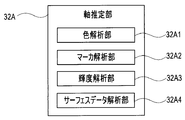
- FIG. 3B is a block diagram illustrating a configuration of the axis estimation unit 32A. The operation of each unit in the axis estimating unit 32A shown in FIG. 3B will be described later in corresponding parts in the following description.
- FIG. 3B shows not only the configuration according to the present embodiment described below, but also the configurations according to the second to sixth embodiments described after the present embodiment.
- the boundary estimation unit 32B is a circuit that estimates the insertion source side (the base end side, the side far from the distal end part 6) as a boundary in the insertion unit 9 reflected in the endoscope image.
- the landmark position estimating unit 32C is a circuit that estimates the position of the landmark using the estimated center axis of the insertion unit 9 of the endoscope 1 and the boundary between the insertion unit 9 and the subject.
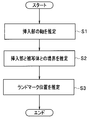
- FIG. 4 is a flowchart illustrating an example of the flow of a landmark estimation process in the landmark estimation unit 32.
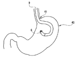
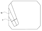
- FIG. 5 is a schematic diagram showing an example of a landmark to be detected. As shown in FIG. 5, the situation in which the insertion section 9 of the endoscope 2 is curved and the subject is photographed in a posture in which the distal end portion 6 is turned back is other than when observing a tumor near the pylorus 41 of the stomach 40 as shown in FIG. And observation of a tumor near the anus of the large intestine, and inspection of an access port of an aircraft engine in an industrial endoscope. In the case of FIG. 5, the pylorus 9 as a hole into which the insertion portion 9 is inserted into the stomach serves as a landmark.
- the control unit 22a controls the driving of the light source and the driving of the imaging element of the endoscope 2 and the imaging signal acquisition unit 21, so that the calculation unit 22b To acquire the imaging signal from the.
- the image generation unit 31 of the calculation unit 22b generates an endoscope image based on the imaging signal under the control of the control unit 22a.
- FIG. 6A is a diagram illustrating an example of an endoscope image generated by the image generation unit 31.
- the landmark estimation unit 32 estimates the axis of the insertion unit 9 based on the generated endoscope image (S1).
- the process of S1 involves the axis estimation unit 32A in FIG. 3A.
- the axis can be estimated by, for example, extracting the insertion section 9 from the endoscope image and specifying the longitudinal direction of the insertion section 9.
- the landmark estimation unit 32 estimates the boundary between the extracted insertion unit 9 and the subject (S2).
- the process of S2 involves the boundary estimation unit 32B in FIG. 3A.
- the distal end side of the insertion section 9 is always located on the peripheral side of the endoscope image, and the insertion source side of the insertion section 9 is always located on the center side of the endoscope image.
- the boundary line that intersects the longitudinal direction of the insertion portion 9 and is located on the center side of the endoscope image can be estimated as the boundary between the insertion section 9 and the subject.
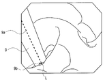
- FIG. 6B is a schematic diagram illustrating landmark positions estimated based on the endoscope image of FIG. 6A.
- the position of the landmark L can be estimated as the intersection of the axis 9a of the insertion section 9 estimated in S1 and the boundary 9b estimated in S2.
- the insertion section itself is reflected in the endoscope image by bending the insertion section of the endoscope, so that the landmark is shielded and directly Even when it cannot be designated as a measurement point, the position of the landmark can be accurately estimated.
- the axis 9a of the insertion section 9 is estimated by detecting the longitudinal direction of the insertion section 9, but in the present embodiment, the axis 9a is detected using image processing.
- the endoscope device according to the present embodiment has the same configuration as the endoscope device 1 according to the first embodiment, and the same components are denoted by the same reference numerals and description thereof is omitted. Further, the landmark estimation processing of the present embodiment is performed in the same procedure as the flowchart shown in FIG. However, the specific method of S1 is different from that of the first embodiment.
- the method of S1 of FIG. 4 according to the present embodiment that is, a specific method of estimating the axis 9a of the insertion portion 9 will be described. Note that the processing of S1 in the present embodiment involves the color analysis unit 32A1 in FIG. 3B.
- FIG. 7 is a schematic diagram illustrating the estimated position of the shaft 9a of the insertion portion 9 according to the second embodiment.
- FIG. 7 shows a state in which processing described later is performed on the endoscope image shown in FIG. 6A and an edge of the insertion section 9 is detected.
- the color analysis section 32A1 of the axis estimation section 32A uses the difference between the color of the insertion section 9 (for example, black) and the color in the body cavity (red) to determine the position of the insertion section 9A.
- the region and the body cavity region are divided, and the edge of the insertion section 9 is detected.
- Existing methods such as Hough transform can be used for edge detection.
- ⁇ Based on the detected edge, calculate a straight line (center line) along the longitudinal direction of the insertion portion 9 that bisects the radial width of the insertion portion 9. For the calculation of the center line, an existing method such as principal axis extraction based on an image moment may be used. The center line thus obtained is estimated as the axis 9a of the insertion section 9.
- the axis 9a of the insertion unit 9 is estimated by detecting the edge of the insertion unit 9 by color analysis.
- the marker provided on the insertion unit 9 is used.
- the endoscope device of this modification has the same configuration as the endoscope device 1 of the first embodiment, and the same components are denoted by the same reference numerals and description thereof will be omitted.
- the landmark estimation processing of the present embodiment is performed in the same procedure as the flowchart shown in FIG.
- the specific method of S1 is different from that of the second embodiment.
- a method of S1 in FIG. 4 according to the present modification that is, a specific method of estimating the axis 9a of the insertion portion 9 will be described. Note that the processing of S1 in the present modification involves the marker analysis unit 32A2 in FIG. 3B.
- FIG. 8 is a schematic diagram illustrating the estimated position of the shaft 9a of the insertion section 9 according to a modification of the second embodiment.
- the insertion section 9 of the endoscope 1 is provided with a marker 9d at a fixed position (or a fixed interval) from the distal end.
- the marker 9d is provided with a marker having a color different from the color of the insertion section 9 so that the marker 9d can be easily recognized on the endoscope image.
- the color of the insertion portion 9 is black, a white marker 9d that is the opposite color is provided.
- the marker 9d is always identifiable on the endoscope image regardless of the insertion state of the insertion section 9, such as the insertion direction, insertion depth, and insertion direction. Therefore, for example, the markers 9d having a shape that makes a round around the outer edge of the insertion portion 9d along the radial direction of the insertion portion 9 are arranged at regular intervals from the tip.
- the marker analysis unit 32A2 of the axis estimation unit 32A detects the marker 9d from the endoscope image based on information about the shape and color of the marker stored in the storage unit 23 or the like in advance.
- the direction orthogonal to the line segment detected as the marker 9d is defined as the axis. Estimate as direction.
- the axis estimation method differs depending on the shape of the marker 9d. For example, when a marker 9d having a linear shape with scales added at regular intervals, such as a number line, is arranged along the longitudinal direction of the insertion section 9, the same direction as the marker 9d is estimated as the axial direction. .
- the longitudinal direction, edge, marker, and the like of the insertion section 9 are extracted from the endoscope image, and the axis 9a is estimated based on the information. The difference is that the axis 9a is estimated using the luminance information.
- the endoscope device of this modification has the same configuration as the endoscope device 1 of the first embodiment, and the same components are denoted by the same reference numerals and description thereof will be omitted.
- the landmark estimation processing of the present embodiment is performed in the same procedure as the flowchart shown in FIG.
- the specific method of S1 is different from that of the second embodiment.
- a method of S1 in FIG. 4 according to the present modification that is, a specific method of estimating the axis 9a of the insertion portion 9 will be described. Note that the processing of S1 in this modification involves the luminance analysis unit 32A3 in FIG. 3B.
- FIG. 9 is a schematic diagram illustrating the estimated position of the shaft 9a of the insertion section 9 according to the third embodiment.
- the brightness analysis unit 32A3 calculates the brightness value of each pixel in the endoscope image shown in FIG. 6A.
- the surface of the insertion section 9 is mirror-finished. Therefore, the illumination light applied to the body cavity is specularly reflected on the surface of the insertion section 9. Since the insertion section 9 is substantially cylindrical, the reflection angle becomes smaller as the insertion section 9 is closer to the axis 9 a of the insertion section 9, and the reflected light is perpendicularly incident on the imaging surface arranged at the distal end portion 6.
- the farther the edge is from the axis 9a of the insertion portion and the closer to the edge the larger the incident angle of the reflected light is, and the reflected light is incident on the imaging surface arranged at the distal end portion 6 with an inclination.
- the luminance value increases as the pixel is located closer to the axis 9a of the insertion section 9, and the luminance value decreases as the distance from the axis 9a increases.
- the axis 9a can be stably estimated.
- the brightness analysis unit 32A3 may be used to determine whether or not the axis 9a estimated in the above-described embodiment or the modified example exists in the high brightness area. In this case, the axis 9a erroneously estimated can be eliminated, so that the estimation accuracy of the axis 9a is improved.
- the same effects as those of the first and second embodiments can be obtained. Furthermore, the detection accuracy of the shaft 9a can be improved by combining with the first and second embodiments.
- the landmark is estimated based on the two-dimensional endoscope image.
- the three-dimensional endoscope image (3D surface data) is acquired, and the landmark is estimated based on the acquired three-dimensional endoscope image (3D surface data). Is estimated.
- the endoscope apparatus according to the present embodiment has the same configuration as the endoscope apparatus 1 according to the first embodiment, except for a means for acquiring 3D surface data provided in the endoscope 2, and is the same. Constituent elements are denoted by the same reference numerals and description thereof is omitted.
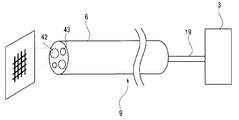
- FIG. 10 is a schematic diagram illustrating an example of the configuration of the endoscope 2 according to the present embodiment.
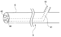
- the endoscope 2 of the present embodiment includes a projection-type measurement device 41 as a unit for acquiring 3D surface data.
- the projection-type measurement device 41 irradiates projection light to the subject, that is, a TOF (Time $ Flight) method, and detects reflected light from the subject.
- the three-dimensional coordinates of the subject are calculated based on the measured time by measuring the time from the irradiation of the projection light to the detection of the reflected light.
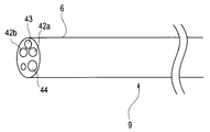
- the projection-type measurement device 41 is inserted from, for example, the treatment instrument channel insertion unit 18, passes through the operation unit 10 and the insertion unit 9, and emits projection light from the treatment instrument channel 44 provided at the distal end 6.
- the reflected light from the subject enters from the treatment instrument channel 44 is detected by a detection unit (not shown) of the projection type measurement device 41, and the time required for the detection is measured.
- the reflected light from the subject may be detected through a window other than the treatment instrument channel 44 provided on the distal end portion 6. For example, a configuration may be adopted in which detection is performed by the imaging device via the observation window 42.
- the projection-type measuring device 41 may be a device using any method as long as the device can acquire 3D surface data in a non-contact manner. Instead of calculating coordinates, other methods such as a pattern projection method (a method of projecting a specific known pattern such as a grid pattern or the like onto a subject and calculating three-dimensional surface data of the subject from distortion of a pattern photographed by an image sensor) are used. May be used.
- a pattern projection method a method of projecting a specific known pattern such as a grid pattern or the like onto a subject and calculating three-dimensional surface data of the subject from distortion of a pattern photographed by an image sensor
- FIG. 11 is a schematic diagram illustrating another example of the configuration of the endoscope 2 according to the fourth embodiment.
- FIG. 12 is a schematic diagram illustrating another example of the configuration of the endoscope 2 according to the fourth embodiment.
- FIG. 13 is a schematic diagram illustrating the estimated position of the shaft 9a of the insertion portion 9 according to the fourth embodiment.
- the surface data analysis unit 32A acquires 3D surface data of the subject. An edge in the longitudinal direction of the insertion section 9 of the endoscope 2 is detected based on the surface data.
- an edge 9 e of the insertion portion 9 an edge 9 e 1 that can be obtained as surface data is indicated by a solid line, and an edge 9 a 2 that cannot be obtained as surface data is indicated by a broken line.
- the edge 9e1 that can be obtained as surface data is estimated as the axis 9a of the insertion section 9.
- the cross-sectional shape (elliptical shape) of the insertion section 9 is estimated from the surface data of the boundary between the insertion section 9 and the body cavity, and a straight line that passes through the center of the estimated cross section and is parallel to the edge 9e1 that can be acquired as surface data is used as an axis. 9a.
- FIG. 14 is a schematic diagram illustrating another estimated position of the shaft 9a of the insertion section 9 according to the fourth embodiment.
- the cross-sectional shape of the insertion section 9 may be estimated from surface data, or design data of the cross-section shape of the insertion section 9 is stored in advance in a storage unit (not shown) provided in the endoscope 2 and is referred to. May be.
- the landmark is estimated. Specifically, the intersection of the plane Sb detected as the body cavity (for example, the stomach wall) from the 3D surface data and the axis 9a estimated in S1 is estimated as the landmark L.
- the endoscope device according to the present embodiment has the same configuration as the endoscope device 1 according to the first embodiment, and the same components are denoted by the same reference numerals and description thereof is omitted.
- the configuration of the calculation unit 22b different from that of the first embodiment will be described.
- FIG. 15 is a block diagram showing the configuration of the calculation unit 22b of the control calculation unit 22 according to the fifth embodiment of the present invention.
- the calculation unit 22b of the present embodiment includes a lesion detection unit 33 and a distance analysis unit 34 in addition to the image generation unit 31 and the landmark estimation unit 32.
- the lesion detection unit 33 performs, for example, a process of applying, to the endoscopic image, an image classifier that has previously acquired a function capable of identifying a tumor (polyp) image by a learning method such as deep learning. To detect a lesion.
- the detection of the lesion area is not limited to the learning method described above, and another method may be used.
- a polyp candidate detection process as disclosed in JP-A-2007-244518 may be used.
- the distance analysis unit 34 calculates the distance between the lesion and the landmark. Note that the distance between the two points may be calculated as a straight-line distance, or when the 3D surface data of the subject has been obtained, the creeping distance along the inner surface of the body cavity may be obtained.
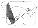
- FIG. 16 is a schematic diagram showing a linear distance between a landmark and a lesion.
- the distance analysis unit 34 connects the estimated landmark L and the detected lesioned part T with a straight line, and calculates the distance between them, as shown in FIG.
- FIG. 17 is a schematic diagram illustrating a creepage distance between a landmark and a lesion.
- the distance analysis unit 34 connects the estimated landmark L and the detected lesioned part T with a straight line, and calculates the distance between them.
- the same effect as that of the first embodiment can be obtained, and the distance to the lesion is measured using the estimated position of the landmark. And useful information for the operator's procedure can be generated and presented.
- the endoscope apparatus has the same configuration as the endoscope apparatus 1 according to the first embodiment, except for a unit that detects the bending of the insertion section 9 provided in the endoscope 2.
- the same components are denoted by the same reference numerals, and description thereof will be omitted.
- FIG. 18 is a schematic diagram illustrating an example of the configuration of the endoscope 2 according to the present embodiment.
- the endoscope 2 of the present embodiment the endoscope 2 is provided with a wire 51 for bending the insertion section 9.
- One end of the wire is connected to the pressure sensing device 52.
- the pressure sensing device 52 detects this.
- the detection result by the pressure-sensitive device 52 is output to the control calculation unit 22.
- the means for detecting the bending of the insertion section 9 is not limited to the detection by the pressure-sensitive device 52 described above, and other means may be used.
- the control operation unit 22 executes each process in the landmark estimation unit 32 only when the pressure-sensitive device 52 detects the wire pressure.
- the bending angle of the insertion section 9 may be estimated from the wire pressure detected by the pressure sensing device 52 and used for estimating the axis 9a of the insertion section.
- the insertion section itself is reflected in the endoscope image by curving the endoscope insertion section, so that the landmark is shielded and directly Even when the measurement point cannot be specified, the position of the landmark can be accurately estimated.
Landscapes
- Engineering & Computer Science (AREA)
- Physics & Mathematics (AREA)
- General Physics & Mathematics (AREA)
- Health & Medical Sciences (AREA)
- Theoretical Computer Science (AREA)
- Computer Vision & Pattern Recognition (AREA)
- Life Sciences & Earth Sciences (AREA)
- Optics & Photonics (AREA)
- Surgery (AREA)
- General Health & Medical Sciences (AREA)
- Nuclear Medicine, Radiotherapy & Molecular Imaging (AREA)
- Medical Informatics (AREA)
- Radiology & Medical Imaging (AREA)
- Multimedia (AREA)
- Biomedical Technology (AREA)
- Veterinary Medicine (AREA)
- Pathology (AREA)
- Molecular Biology (AREA)
- Animal Behavior & Ethology (AREA)
- Biophysics (AREA)
- Public Health (AREA)
- Heart & Thoracic Surgery (AREA)
- Astronomy & Astrophysics (AREA)
- Signal Processing (AREA)
- Quality & Reliability (AREA)
- Geometry (AREA)
- Gastroenterology & Hepatology (AREA)
- Endoscopes (AREA)
- Instruments For Viewing The Inside Of Hollow Bodies (AREA)
Abstract
Ce procédé d'estimation de repère estime, dans une image endoscopique obtenue par imagerie d'un sujet avec un endoscope (2) possédant une section d'insertion (9) courbée, la position d'un repère L, qui est un orifice présent dans le sujet et qui est un site traversé par la section d'insertion (9), le procédé consistant à estimer un axe (9a) de la section d'insertion (9), à estimer une limite (9b) entre la section d'insertion (9) et le sujet, et, sur la base de l'axe (9a) estimé et de la limite (9b), à estimer la position du repère L.
Priority Applications (4)
| Application Number | Priority Date | Filing Date | Title |
|---|---|---|---|
| CN201880092227.XA CN111936030B (zh) | 2018-06-22 | 2018-06-22 | 界标估计方法、内窥镜装置及存储介质 |
| JP2020525202A JP6987243B2 (ja) | 2018-06-22 | 2018-06-22 | ランドマーク推定方法、内視鏡装置、及び、位置推定プログラム |
| PCT/JP2018/023833 WO2019244345A1 (fr) | 2018-06-22 | 2018-06-22 | Procédé d'estimation de repères et dispositif endoscopique |
| US17/093,800 US11430114B2 (en) | 2018-06-22 | 2020-11-10 | Landmark estimating method, processor, and storage medium |
Applications Claiming Priority (1)
| Application Number | Priority Date | Filing Date | Title |
|---|---|---|---|
| PCT/JP2018/023833 WO2019244345A1 (fr) | 2018-06-22 | 2018-06-22 | Procédé d'estimation de repères et dispositif endoscopique |
Related Child Applications (1)
| Application Number | Title | Priority Date | Filing Date |
|---|---|---|---|
| US17/093,800 Continuation US11430114B2 (en) | 2018-06-22 | 2020-11-10 | Landmark estimating method, processor, and storage medium |
Publications (1)
| Publication Number | Publication Date |
|---|---|
| WO2019244345A1 true WO2019244345A1 (fr) | 2019-12-26 |
Family
ID=68983652
Family Applications (1)
| Application Number | Title | Priority Date | Filing Date |
|---|---|---|---|
| PCT/JP2018/023833 Ceased WO2019244345A1 (fr) | 2018-06-22 | 2018-06-22 | Procédé d'estimation de repères et dispositif endoscopique |
Country Status (4)
| Country | Link |
|---|---|
| US (1) | US11430114B2 (fr) |
| JP (1) | JP6987243B2 (fr) |
| CN (1) | CN111936030B (fr) |
| WO (1) | WO2019244345A1 (fr) |
Cited By (2)
| Publication number | Priority date | Publication date | Assignee | Title |
|---|---|---|---|---|
| WO2021221017A1 (fr) * | 2020-04-28 | 2021-11-04 | Hoya株式会社 | Système endoscope |
| JPWO2022202400A1 (fr) * | 2021-03-22 | 2022-09-29 |
Families Citing this family (4)
| Publication number | Priority date | Publication date | Assignee | Title |
|---|---|---|---|---|
| EP4306035A4 (fr) * | 2021-03-09 | 2024-10-30 | FUJIFILM Corporation | Système d'endoscope et son procédé de fonctionnement |
| JPWO2022191128A1 (fr) * | 2021-03-09 | 2022-09-15 | ||
| WO2023276327A1 (fr) * | 2021-06-29 | 2023-01-05 | 浜松ホトニクス株式会社 | Procédé de traitement d'image optique, procédé d'apprentissage automatique, modèle appris, procédé de prétraitement d'apprentissage automatique, module de traitement d'image optique, programme de traitement d'image optique et système de traitement d'image optique |
| US20250285237A1 (en) * | 2024-03-08 | 2025-09-11 | University Of Southern California | Processing multiplex images and analysis of immune enriched spatial proteomic data |
Citations (3)
| Publication number | Priority date | Publication date | Assignee | Title |
|---|---|---|---|---|
| WO2006087981A1 (fr) * | 2005-02-15 | 2006-08-24 | Olympus Corporation | Dispositif de traitement d'images medicales, dispositif et procede de traitement d'image d'une lumiere et programmes leur etant destines |
| JP2009201682A (ja) * | 2008-02-27 | 2009-09-10 | Hitachi Ltd | 回転状態検出方法および装置 |
| JP2012070938A (ja) * | 2010-09-28 | 2012-04-12 | Fujifilm Corp | 内視鏡画像記録装置、及び内視鏡画像記録支援方法、並びにプログラム |
Family Cites Families (29)
| Publication number | Priority date | Publication date | Assignee | Title |
|---|---|---|---|---|
| CN101065052B (zh) * | 2004-12-27 | 2010-12-22 | 奥林巴斯株式会社 | 医疗图像处理装置和医疗图像处理方法 |
| JP4668624B2 (ja) * | 2005-01-07 | 2011-04-13 | オリンパス株式会社 | 食道粘膜用画像処理装置 |
| JP4832927B2 (ja) * | 2006-03-14 | 2011-12-07 | オリンパスメディカルシステムズ株式会社 | 医療用画像処理装置及び医療用画像処理方法 |
| JP2008237236A (ja) * | 2007-03-23 | 2008-10-09 | Olympus Medical Systems Corp | 内視鏡及び生体観察システム |
| CN101652092B (zh) * | 2007-06-20 | 2011-09-07 | 奥林巴斯医疗株式会社 | 内窥镜系统、摄像系统以及图像处理装置 |
| WO2009069395A1 (fr) * | 2007-11-29 | 2009-06-04 | Olympus Medical Systems Corp. | Dispositif de commande de courbure d'endoscope et système d'endoscope |
| JP5291955B2 (ja) * | 2008-03-10 | 2013-09-18 | 富士フイルム株式会社 | 内視鏡検査システム |
| JP2009254783A (ja) * | 2008-03-25 | 2009-11-05 | Panasonic Electric Works Co Ltd | 内視鏡システム、内視鏡手術訓練システム |
| US10004387B2 (en) * | 2009-03-26 | 2018-06-26 | Intuitive Surgical Operations, Inc. | Method and system for assisting an operator in endoscopic navigation |
| EP3859682A1 (fr) * | 2009-03-26 | 2021-08-04 | Intuitive Surgical Operations, Inc. | Système de fourniture d'un guidage visuel pour diriger l'embout d'un dispositif endoscopique vers un ou plusieurs repères et assister un opérateur lors d'une navigation endoscopique |
| JP4709946B2 (ja) * | 2009-06-01 | 2011-06-29 | オリンパスメディカルシステムズ株式会社 | 医療機器システムおよび医療器具のキャリブレーション方法 |
| US8870751B2 (en) | 2010-09-28 | 2014-10-28 | Fujifilm Corporation | Endoscope system, endoscope image recording apparatus, endoscope image acquisition assisting method and computer readable medium |
| US9875574B2 (en) * | 2013-12-17 | 2018-01-23 | General Electric Company | Method and device for automatically identifying the deepest point on the surface of an anomaly |
| US10019812B2 (en) * | 2011-03-04 | 2018-07-10 | General Electric Company | Graphic overlay for measuring dimensions of features using a video inspection device |
| EP2785237B1 (fr) * | 2011-12-03 | 2020-09-30 | Koninklijke Philips N.V. | Localisation d'un orifice chirurgical |
| WO2013175939A1 (fr) * | 2012-05-23 | 2013-11-28 | オリンパスメディカルシステムズ株式会社 | Système d'endoscope électronique |
| WO2014171391A1 (fr) * | 2013-04-15 | 2014-10-23 | オリンパスメディカルシステムズ株式会社 | Système d'endoscope |
| DE102013219134A1 (de) * | 2013-09-24 | 2015-03-26 | Siemens Aktiengesellschaft | System und Verfahren zur Korrelation von Objektinformationen mit Röntgenbildern |
| US20150142372A1 (en) * | 2013-11-19 | 2015-05-21 | Polaris Surgical, LLC | Prosthetic placement tool and associated methods |
| EP3064122A4 (fr) * | 2013-12-05 | 2017-09-06 | Olympus Corporation | Système d'endoscope stéréoscopique |
| US9600928B2 (en) * | 2013-12-17 | 2017-03-21 | General Electric Company | Method and device for automatically identifying a point of interest on the surface of an anomaly |
| CN106068093B (zh) * | 2014-04-08 | 2018-09-25 | 奥林巴斯株式会社 | 内窥镜系统 |
| JP6446251B2 (ja) | 2014-10-13 | 2018-12-26 | ゼネラル・エレクトリック・カンパニイ | 異常の表面上の関心点を自動的に識別するための方法およびデバイス |
| JP6013664B1 (ja) * | 2014-12-10 | 2016-10-25 | オリンパス株式会社 | 補助具及び内視鏡システム |
| WO2017054817A1 (fr) * | 2015-10-01 | 2017-04-06 | Olaf Christiansen | Système endoscopique de traitement d'image destiné a la chirurgie, pourvu de moyens générant une information de distance géométrique dans la plage de prise de vues d'une caméra numérique optique |
| WO2017081821A1 (fr) * | 2015-11-13 | 2017-05-18 | オリンパス株式会社 | Procédé d'estimation d'état d'endoscope |
| JP2018050890A (ja) * | 2016-09-28 | 2018-04-05 | 富士フイルム株式会社 | 画像表示装置及び画像表示方法並びにプログラム |
| JP6824078B2 (ja) * | 2017-03-16 | 2021-02-03 | 富士フイルム株式会社 | 内視鏡位置特定装置、方法およびプログラム |
| ES3025886T3 (en) * | 2018-01-04 | 2025-06-10 | Applied Med Resources | Surgical simulation camera scope |
-
2018
- 2018-06-22 CN CN201880092227.XA patent/CN111936030B/zh active Active
- 2018-06-22 WO PCT/JP2018/023833 patent/WO2019244345A1/fr not_active Ceased
- 2018-06-22 JP JP2020525202A patent/JP6987243B2/ja active Active
-
2020
- 2020-11-10 US US17/093,800 patent/US11430114B2/en active Active
Patent Citations (3)
| Publication number | Priority date | Publication date | Assignee | Title |
|---|---|---|---|---|
| WO2006087981A1 (fr) * | 2005-02-15 | 2006-08-24 | Olympus Corporation | Dispositif de traitement d'images medicales, dispositif et procede de traitement d'image d'une lumiere et programmes leur etant destines |
| JP2009201682A (ja) * | 2008-02-27 | 2009-09-10 | Hitachi Ltd | 回転状態検出方法および装置 |
| JP2012070938A (ja) * | 2010-09-28 | 2012-04-12 | Fujifilm Corp | 内視鏡画像記録装置、及び内視鏡画像記録支援方法、並びにプログラム |
Cited By (7)
| Publication number | Priority date | Publication date | Assignee | Title |
|---|---|---|---|---|
| WO2021221017A1 (fr) * | 2020-04-28 | 2021-11-04 | Hoya株式会社 | Système endoscope |
| JPWO2021221017A1 (fr) * | 2020-04-28 | 2021-11-04 | ||
| JP7234461B2 (ja) | 2020-04-28 | 2023-03-07 | Hoya株式会社 | 内視鏡システム |
| US12419503B2 (en) | 2020-04-28 | 2025-09-23 | Hoya Corporation | Endoscope system having a three-dimensional expansion processor |
| JPWO2022202400A1 (fr) * | 2021-03-22 | 2022-09-29 | ||
| WO2022202400A1 (fr) * | 2021-03-22 | 2022-09-29 | 富士フイルム株式会社 | Dispositif de traitement d'image, procédé de traitement d'image et programme |
| JP7792950B2 (ja) | 2021-03-22 | 2025-12-26 | 富士フイルム株式会社 | 画像処理装置、画像処理方法、及びプログラム |
Also Published As
| Publication number | Publication date |
|---|---|
| JP6987243B2 (ja) | 2021-12-22 |
| US11430114B2 (en) | 2022-08-30 |
| CN111936030A (zh) | 2020-11-13 |
| JPWO2019244345A1 (ja) | 2021-02-25 |
| US20210056695A1 (en) | 2021-02-25 |
| CN111936030B (zh) | 2024-09-20 |
Similar Documents
| Publication | Publication Date | Title |
|---|---|---|
| US11430114B2 (en) | Landmark estimating method, processor, and storage medium | |
| JP5676058B1 (ja) | 内視鏡システム及び内視鏡システムの作動方法 | |
| KR102163327B1 (ko) | 수술 시스템의 효율적인 쌍방향 출혈 검출 방법 및 시스템 | |
| CN105050479B (zh) | 内窥镜系统 | |
| KR102087595B1 (ko) | 내시경 시스템 및 그 제어방법 | |
| JP7385731B2 (ja) | 内視鏡システム、画像処理装置の作動方法及び内視鏡 | |
| JP7770392B2 (ja) | 医療処置中に未検査領域を識別するためのデバイス、システム、及び方法 | |
| US12299922B2 (en) | Luminal structure calculation apparatus, creation method for luminal structure information, and non-transitory recording medium recording luminal structure information creation program | |
| JP2020516408A (ja) | 内視鏡測定の方法および器具 | |
| US12433478B2 (en) | Processing device, endoscope system, and method for processing captured image | |
| US11432707B2 (en) | Endoscope system, processor for endoscope and operation method for endoscope system for determining an erroneous estimation portion | |
| CN116940274A (zh) | 内窥镜用形状测量系统及内窥镜用形状测量方法 | |
| CN115279250B (zh) | 内窥镜系统 | |
| US20240000299A1 (en) | Image processing apparatus, image processing method, and program | |
| WO2022230563A1 (fr) | Système d'endoscope et son procédé de fonctionnement | |
| US20240013389A1 (en) | Medical information processing apparatus, endoscope system, medical information processing method, and medical information processing program | |
| JPWO2022202520A5 (fr) | ||
| JP6335839B2 (ja) | 医療装置、医療画像生成方法及び医療画像生成プログラム |
Legal Events
| Date | Code | Title | Description |
|---|---|---|---|
| 121 | Ep: the epo has been informed by wipo that ep was designated in this application |
Ref document number: 18923215 Country of ref document: EP Kind code of ref document: A1 |
|
| ENP | Entry into the national phase |
Ref document number: 2020525202 Country of ref document: JP Kind code of ref document: A |
|
| NENP | Non-entry into the national phase |
Ref country code: DE |
|
| 122 | Ep: pct application non-entry in european phase |
Ref document number: 18923215 Country of ref document: EP Kind code of ref document: A1 |